EP3170639B1 - Verfahren zur steuerung der geschwindigkeit und der positionierung eines werkzeugwechselwagens sowie arbeitsstation für eine mit auswechselbaren werkzeugen bestückte maschine - Google Patents
Verfahren zur steuerung der geschwindigkeit und der positionierung eines werkzeugwechselwagens sowie arbeitsstation für eine mit auswechselbaren werkzeugen bestückte maschine Download PDFInfo
- Publication number
- EP3170639B1 EP3170639B1 EP16196912.6A EP16196912A EP3170639B1 EP 3170639 B1 EP3170639 B1 EP 3170639B1 EP 16196912 A EP16196912 A EP 16196912A EP 3170639 B1 EP3170639 B1 EP 3170639B1
- Authority
- EP
- European Patent Office
- Prior art keywords
- tool change
- carriage
- tools
- work station
- change carriage
- Prior art date
- Legal status (The legal status is an assumption and is not a legal conclusion. Google has not performed a legal analysis and makes no representation as to the accuracy of the status listed.)
- Revoked
Links
Images
Classifications
-
- B—PERFORMING OPERATIONS; TRANSPORTING
- B29—WORKING OF PLASTICS; WORKING OF SUBSTANCES IN A PLASTIC STATE IN GENERAL
- B29C—SHAPING OR JOINING OF PLASTICS; SHAPING OF MATERIAL IN A PLASTIC STATE, NOT OTHERWISE PROVIDED FOR; AFTER-TREATMENT OF THE SHAPED PRODUCTS, e.g. REPAIRING
- B29C45/00—Injection moulding, i.e. forcing the required volume of moulding material through a nozzle into a closed mould; Apparatus therefor
- B29C45/17—Component parts, details or accessories; Auxiliary operations
- B29C45/1756—Handling of moulds or mould parts, e.g. mould exchanging means
-
- B—PERFORMING OPERATIONS; TRANSPORTING
- B29—WORKING OF PLASTICS; WORKING OF SUBSTANCES IN A PLASTIC STATE IN GENERAL
- B29C—SHAPING OR JOINING OF PLASTICS; SHAPING OF MATERIAL IN A PLASTIC STATE, NOT OTHERWISE PROVIDED FOR; AFTER-TREATMENT OF THE SHAPED PRODUCTS, e.g. REPAIRING
- B29C31/00—Handling, e.g. feeding of the material to be shaped, storage of plastics material before moulding; Automation, i.e. automated handling lines in plastics processing plants, e.g. using manipulators or robots
- B29C31/006—Handling moulds, e.g. between a mould store and a moulding machine
Definitions
- the invention relates to a method for controlling the speed and the positioning of a tool change carriage guided on rails and loaded with tools.
- the invention also relates to a work station for a machine equipped with interchangeable tools, with a tool change trolley loaded to transport tools in and out, which can be guided along a travel path and its position, in particular when picking up or releasing tools by means of a sensor connected to a control device is detectable.
- the US 2011/0193253 A1 relates to a method of controlling self-propelled trolleys for casting molds, each of which includes a trolley location indicator which determines the location of the trolley, which is substantially continuously transmitted to a trolley controller and then relayed to a primary controller. From there, position instructions, for example for a polymer filling station, are forwarded to each trolley controller, which provides the respective drive system of each trolley with corresponding instructions on the operating position.
- the car position display which contains a processor with a triangulation algorithm, interacts with two or more separate and stationary position displays, for example by means of reflected laser light, and thereby determines the position of the car by means of triangulation. Position instructions are transmitted from the carriage control to the drive motor of the carriage via a wire connection.
- the device for changing the mold is equipped with a carriage for transporting the mold, the is driven by motor means on a guide and wherein the injection molds are disposed between a pair of weight bearing clamping plates.
- the device for changing the mold is equipped with a carriage for transporting the mold, the is driven by motor means on a guide and wherein the injection molds are disposed between a pair of weight bearing clamping plates.
- the EP 0 164 062 B1 suggested that the clamping plates protrude at least from the underlying surface of the mold, that the injection molding machine has at least one base on which a fixed plate and a movable plate are mounted, the mold being inserted or moved out between the plates. Furthermore, the carriage should have a pair of work stations and be arranged along the injection molding machine and supported for movement parallel to the movement of the movable plate.
- the device is intended to have roller means for the plates, which are arranged along the lower portion of each plate for supporting the associated clamping plate. The machine is loaded either via a rack system or a driven roller system.
- a roller system of several rollers is driven with a motor via a chain system for each position. The same is used in the machine.
- the fixed side is provided with guide strips to keep the tool on track.
- the moving side receives non-powered rollers.
- Rack assemblies are disposed along the lower surface of at least one of the clamping plates. Furthermore, a machine motor with a drive pinion is mounted for engagement with the rack device, slide roller devices being provided on the slide for receiving and rolling engagement with the clamping plates.
- the plates and the carriage roller devices are arranged in such a way that the clamping plates and the mold are movable to the side of the machine and that the carriage motor with drive gear is mounted on the carriage within the carriage rollers and meshes with the rack devices on the clamping plate with its gear, so that the Rack-and-pinion device engages in series with the drive gear of the machine motor and one of the drive gears of the carriage motor during the mold change and the clamping plate and the mold are driven laterally between the machine and the carriage. Impeller motors are used as drives.
- proximity switches are provided which, when triggered mechanically, control the impeller motors.
- proximity switches have the disadvantage that the tool change carriage can only be moved very slowly.
- positional inaccuracies cannot always be avoided, so that if the tool change carriage is incorrectly positioned, the tool change in the worst case prevents, at least is made more difficult by the fact that the tool change carriage has to be repositioned.
- a laser is used both to determine the distance and to control the speed of the tool change carriage.
- the invention according to the work station is characterized in that the sensor is a laser which serves both as a range finder and for measuring the speed of the tool change carriage.
- a laser enables non-contact distance and speed measurement, which is why the sensor works without wear.
- maximum speeds can be selected that lead to considerable time savings.
- the tool change carriage is only braked shortly before reaching the locations of a change in direction of movement or the tool change position.
- a laser sensor enables exact distance measurement and thus exact positioning of the tool change trolley.
- a laser is preferably used which is designed to emit short pulses, a receiver being provided for detecting the pulses reflected by the tool change carriage.
- a method also known as pulse ranging technology, works with high-energy pulse trains, of which z. B. sent out 200,000 pulses / second and received again by the receiver after the reflection on the tool change carriage. The exact position of the tool change carriage and the distance to the tool change location can thus be determined at any time from the pulse sequence.
- This method or such devices from a transmitter / receiver unit work extremely precisely, interference-free and error-free.
- the tool change carriages used which can be moved along guide tracks crossing at right angles, were equipped with reflectors.
- the tool change trolleys had to be moved precisely to the tool change station for the inward and outward conveyance of heavy tools and anchored there for the tool change, as well as being redirected to a change in movement at the intersection.
- a transceiver device was used as the control device, in which a laser was arranged, which emitted a large number of high-energy pulses per second.
- the control device also contained a receiver which received the signals reflected from the tool change carriage and passed them on to a control device for the tool change carriage.
- a deflecting prism was also pushed into the beam path.
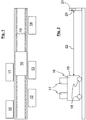
- Fig. 1 it can be seen that two injection molding machines 10 and 11 are lined up in a first row and injection molding machines 12, 13 and 14 are lined up in a row arranged parallel thereto. Between these two rows there is a running rail 15, along which a tool changing carriage 16 can be moved.
- the tool change trolley is like from Fig. 2 to see, loaded with injection molding tools 17, which have to be transported to an injection molding machine when changing tools.
- a robot is preferably used, which releases the injection molding tools to be replaced from the injection molding machine and places them on the tool change trolley.
- the "new" injection molding tools are then removed from the tool changing carriage and taken to the injection molding machine, where they are appropriately assembled, for example by actuating a quick-release device.
- the tool change trolley 16 then has to bring the injection molding tools that are not required back to a storage location and, if necessary, pick up new injection molding tools that have to be moved to another injection molding machine.
- Fig. 1 the running rail is shown linearly, but it is also conceivable to travel on curved tracks or over intersecting rails.
- the die change trolley is equipped with a wheel set 18.
- reflectors are arranged which reflect laser beams 22 emitted by a laser 20 at a fixed stop 21.
- a receiver is also arranged on this fixed stop 21, which detects the reflected laser beams 22 and from the different transit times both via an evaluation unit (not shown in detail but basically known from the prior art) both the distance of the tool change carriage 16 from the fixed stop and its current distance relative speed calculated.
- the position or location determination by laser measurement is exact, so that tool trolley misalignments on injection molding machines or at the storage area are largely excluded.
- the tool change carriage 16 can be driven to the destination at maximum speed. Both the travel times of the tool change carriage and absenteeism as a result of incorrect positioning of the change carriage are avoided, so that the overall tool change speeds are optimized.
Landscapes
- Engineering & Computer Science (AREA)
- Mechanical Engineering (AREA)
- Robotics (AREA)
- Manufacturing & Machinery (AREA)
- Moulds For Moulding Plastics Or The Like (AREA)
- Length Measuring Devices By Optical Means (AREA)
- Mounting, Exchange, And Manufacturing Of Dies (AREA)
Description
- Die Erfindung betrifft ein Verfahren zur Steuerung der Geschwindigkeit und der Positionierung eines auf Schienen geführten und mit Werkzeugen beladenen Werkzeugwechselwagens.
- Die Erfindung betrifft ferner eine Arbeitsstation für eine mit auswechselbaren Werkzeugen bestückte Maschine, mit einem zum An- und Abtransport von Werkzeugen beladenen Werkzeugwechselwagen, der entlang eines Fahrweges führbar ist und dessen Position, insbesondere beim Aufnehmen oder Abgeben von Werkzeugen mittels eines mit einer Steuereinrichtung verbundenen Sensors detektierbar ist.
- Die
US 2011/0193253 A1 betrifft ein Verfahren zur Steuerung von selbstfahrenden Wagen für Gießformen, von denen jeder eine Wagenstandortanzeige enthält, die den Ort des Wagens bestimmt, der im wesentlichen kontinuierlich an eine Wagensteuerungseinrichtung übertragen und dann an eine Primärsteuerung weitergeleitet wird. Von dort aus werden Positionsanweisungen, z.B. für eine Polymereinfüllstation an jede Wagensteuerung weitergeleitet, die dem jeweiligen Antriebsystem jedes Wagens entsprechende Anweisungen zur Betriebsposition bereitstellt. Die Wagenstandortanzeige, die einen Prozessor mit einem Triangulationsalgorithmus enthält, interagiert mit zwei oder mehreren getrennten und stationären Positionsanzeigen, z.B. mittels reflektiertem Laserlicht und bestimmt dadurch die Position des Wagens mittels Triangulation. Über einen Drahtanschluss werden von der Wagensteuerung Positionsanweisungen an den Antriebsmotor des Wagens übertragen. - In der
EP 0 164 062 B1 wird eine Vorrichtung zum Wechseln einer Form in einer horizontalen Kunststoffspritzgießmaschine beschrieben, bei der die Vorrichtung zum Formenwechsel mit einem Schlitten für den Transport der Form ausgestattet ist, der durch eine Motoreinrichtung auf einer Führung angetrieben wird und wobei die Spritzgießformen zwischen einem Paar von gewichttragenden Einspannplatten angeordnet sind. Zum Formenwechsel ist es erforderlich, die Form von den in der Einspritzgießmaschine montierten Einspannplatten zu lösen und die neue Form zwischen den Einspannplatten zu befestigen, wozu eine vorherige genaue Positionierung der neuen Form erforderlich ist. - Um den komplizierten und zeitaufwendigen Arbeitsgang des Formenwechsels zu verkürzen und zu vereinfachen wird in der
EP 0 164 062 B1 vorgeschlagen, dass die Einspannplatten mindestens von der unten liegenden Oberfläche der Form vorstehen, dass die Spritzgießmaschine mindestens eine Basis aufweist, auf der eine feststehende Platte und eine bewegliche Platte gelagert sind, wobei zwischen den Platten die Form eingesetzt oder heraus bewegt werden soll. Ferner soll der Schlitten ein Paar von Arbeitsstationen aufweisen und längs der Spritzgießmaschine angeordnet und für eine Bewegung parallel zur Bewegung der beweglichen Platte gelagert sein. Die Vorrichtung soll Rolleneinrichtungen für die Platten aufweisen, die längs dem unteren Abschnitt jeder Platte zur Lagerung der dazu gehörigen Einspannplatte angeordnet sind. Die Beladung der Maschine erfolgt über wahlweise ein Zahnstangensystem oder über ein angetriebenes Rollensystem. - Auf dem Wechselwagen wird je Position ein Rollensystem mehrerer Rollen mit einem Motor über ein Kettensystem angetrieben. Das gleiche wird in der Maschine verwendet. Die feste Seite ist mit Führungsleisten versehen, um das Werkzeug in Spur zu halten. Die bewegliche Seite erhält nicht angetriebene Rollen.
- Zahnstangeneinrichtungen sind längs der unteren Oberfläche mindestens einer der Einspannplatten angeordnet. Ferner ist ein Maschinenmotor mit einem Antriebritzel für den Eingriff mit der Zahnstangeneinrichtung gelagert, wobei Schlittenrolleneinrichtungen auf dem Schlitten zur Aufnahme und zum rollenden Eingriff mit den Einspannplatten vorgesehen sind. Die Platten und die Schlittenrolleinrichtungen sind derart angeordnet, dass die Einspannplatten und die Form seitlich der Maschine beweglich sind und dass Schlittenmotor mit Antriebszahnrad an dem Schlitten innerhalb der Schlittenrollen gelagert ist und mit den Zahnstangeneinrichtungen an der Einspannplatte mit seinem Zahnrad in Eingriff steht, so dass die Zahnstangeneinrichtung während des Formenwechsels mit dem Antriebszahnrad des Maschinenmotors und einem der Antriebszahnräder des Schlittenmotors in Reihe in Eingriff gelangt und die Einspannplatte und die Form seitlich zwischen der Maschine und dem Schlitten angetrieben wird. Als Antriebe werden Flügelradmotoren verwendet. Um die zum An- und Abtransport der Formteile benutzten Werkzeugwechselwagen entlang der vorgesehenen Fahrwege exakt führen zu können, sind Näherungsschalter vorgesehen, die bei mechanischer Auslösung die Steuerung der Flügelradmotoren bewirken. Näherungsschalter besitzen jedoch den Nachteil, dass der Werkzeugwechselwagen nur sehr langsam bewegt werden kann. Zudem sind Positionsungenauigkeiten nicht immer zu vermeiden, so dass bei einer Fehlpositionierung des Werkzeugwechselwagens der Werkzeugwechsel schlimmstenfalls verhindert, zumindest dadurch erschwert wird, dass der Werkzeugwechselwagen neu positioniert werden muss.
- Lange Umrüstzeiten haben unmittelbaren Einfluss auf die Wirtschaftlichkeit des Fertigungsvorgangs und sollten daher so kurz wie möglich sein.
- Es ist Aufgabe der vorliegenden Erfindung, ein Verfahren und eine Arbeitsstation der eingangs genannten Art mit verkürzten Werkzeugwechselzeiten zu schaffen.
- Diese Aufgabe wird durch ein Verfahren nach Anspruch 1 sowie eine Arbeitsstation nach Anspruch 2 gelöst.
- Bei dem erfindungsgemäßen Verfahren dient ein Laser sowohl zur Bestimmung der Entfernung als auch zur Steuerung der Geschwindigkeit des Werkzeugwechselwagens.
- Die Erfindung gemäß Arbeitsstation ist dadurch gekennzeichnet, dass der Sensor ein Laser ist, der sowohl als Entfernungsmesser als auch zur Messung der Geschwindigkeit des Werkzeugwechselwagens dient.
- Ein Laser ermöglicht eine berührungslose Distanz- und Geschwindigkeitsmessung, weshalb der Sensor verschleißfrei arbeitet. Solange der Werkzeugwechselwagen in Bereichen bewegt wird, die von den Positionen entfernt sind, bei denen die Bewegungsrichtung des Werkzeugwechselwagens geändert oder der Werkzeugwechselwagen zum Werkzeugwechsel exakt positioniert werden muss, können maximale Geschwindigkeiten gewählt werden, die zu einer erheblichen Zeitersparnis führen. Erst kurz vor Erreichen der Orte einer Bewegungsrichtungsänderung oder der Werkzeugwechselposition wird der Werkzeugwechselwagen abgebremst. Zudem lässt ein Laser-Sensor eine exakte Distanzmessung und damit eine exakte Positionierung des Werkzeugwechselwagens verwirklichen.
- Vorzugsweise wird in der erfindungsgemäßen Arbeitsstation ein Laser verwendet, der zur Aussendung kurzer Impulse ausgebildet ist, wobei ein Empfänger zur Detektion der von dem Werkzeugwechselwagen reflektierten Impulse vorgesehen ist. Ein solches auch als Pulse-Ranging-Technology bekanntes Verfahren arbeitet mit hochenergiereichen Impulsfolgen, von denen z. B. 200.000 Impulse/Sekunde ausgesendet und vom Empfänger nach der Reflexion am Werkzeugwechselwagen wieder empfangen werden. Aus der Pulsfolge lässt sich somit zu jedem Zeitpunkt die genaue Lage des Werkzeugwechselwagens als auch die Distanz zum Werkzeugwechselort bestimmen. Dieses Verfahren bzw. solche Vorrichtungen aus einer Sender/Empfängereinheit arbeiten höchst genau, störungsfest und fehlerfrei.
- In einem praktischen Anwendungsbeispiel wurden verwendete Werkzeugwechselwagen, die entlang von sich unter einem rechten Winkel kreuzenden Führungsbahnen bewegbar sind, mit Reflektoren ausgestattet. Die Werkzeugwechselwagen mussten zum Zu- und Abfördern von schweren Werkzeugen sowohl positionsgenau auf die Werkzeugwechselstation bewegt und zum Werkzeugwechsel dort verankert werden als auch am Kreuzungspunkt zu einer Bewegungsänderung umgesteuert werden.
- Als Steuergerät wurde eine Sende-Empfangseinrichtung verwendet, in der ein Laser angeordnet war, der pro Sekunde eine Vielzahl von hochenergetischen Impulsen ausgesendet hat. Ferner war in der Steuereinrichtung ein Empfänger enthalten, der die vom Werkzeugwechselwagen reflektierten Signale aufnahm und an eine Steuereinrichtung für den Werkzeugwechselwagen weitergab. Um den Laserstrahl in unterschiedlichen Richtungen entlang des Fahrweges für die Werkzeugwechselwagen benutzen zu können, wurde zusätzlich ein Umlenkprisma in den Strahlengang geschoben.
- Bei Verwendung der beschriebenen Anordnung konnten bereits auf kurzen Distanzen, auf denen die Werkzeugwechselwagen bewegt werden mussten, Zeiten von frei, so dass Positionsungenauigkeiten der Werkzeugwechselwagen vollständig eliminiert werden konnten.
- Ein Ausführungsbeispiel der Erfindung wird im Folgenden anhand der Zeichnungen erläutert. Es zeigen:
- Fig. 1
- eine Draufsicht auf eine Fahrschiene mit einem Werkzeugwechselwagen, der entlang einer Reihe von Spritzgießmaschinen verfahrbar ist und
- Fig. 2
- eine Prinzipdarstellung der Funktion der Orts- und Geschwindigkeitsbestimmung eines Werkzeugwechselwagens.
- Aus
Fig. 1 ist zu erkennen, dass in einer ersten Reihe zwei Spritzgießmaschinen 10 und 11 und in einer parallel dazu angeordneten Reihe Spritzgießmaschinen 12, 13 und 14 aufgereiht sind. Zwischen diesen beiden Reihen befindet sich eine Fahrschiene 15, entlang der ein Werkzeugwechselwagen 16 verfahrbar ist. Der Werkzeugwechselwagen ist, wie ausFig. 2 zu erkennen, mit Spritzgießwerkzeugen 17 beladen, die beim Werkzeugwechsel an eine Spritzgießmaschine transportiert werden müssen. Zum Werkzeugwechsel wird vorzugsweise ein Roboter verwendet, der die auszuwechselnden Spritzgießwerkzeuge jeweils an der Spritzgießmaschine löst und auf dem Werkzeugwechselwagen ablegt. Die "neuen" Spritzgießwerkzeuge werden anschließend von dem Werkzeugwechselwagen entnommen und zu der Spritzgießmaschine geführt, wo sie entsprechend montiert werden, beispielsweise mittels Betätigung einer Schnellspannvorrichtung. Der Werkzeugwechselwagen 16 muss anschließend die nicht benötigten Spritzgießwerkzeuge wieder an einen Lagerort zurückbringen und ggf. neue Spritzgießwerkzeuge aufnehmen, die zu einer anderen Spritzgießmaschine geführt werden müssen. - In
Fig. 1 ist die Fahrschiene linear dargestellt, es sind jedoch auch Fahrwege auf gekrümmten Bahnen oder über sich kreuzende Fahrschienen denkbar. InFig. 2 ist der Werkzeugwechselwagen mit einem Radsatz 18 ausgestattet. An der Frontseite 19 sind Reflektoren angeordnet, die von einem Laser 20 an einem Festanschlag 21 ausgesandten Laserstrahlen 22 reflektieren. An diesem Festanschlag 21 ist auch ein Empfänger angeordnet, der die reflektierten Laserstrahlen 22 detektiert und aus den unterschiedlichen Laufzeiten sowohl über eine nicht im Einzelnen dargestellte aber nach dem Stand der Technik grundsätzlich bekannte Auswerteinheit sowohl die Entfernung des Werkzeugwechselwagens 16 von dem Festanschlag als auch seine momentane relative Geschwindigkeit errechnet. Die Positions- bzw. Ortsbestimmung per Lasermessung ist exakt, so dass Werkzeugwagenfehlstellungen an Spritzgießmaschinen bzw. am Lagerplatz weitgehend ausgeschlossen sind. Nachdem jeweiligen Werkzeugwechsel bzw. nach der Werkzeugaufnahme kann der Werkzeugwechselwagen 16 mit maximaler Geschwindigkeit zum Bestimmungsort gefahren werden. Sowohl die Fahrzeiten des Werkzeugwechselwagens als auch Fehlzeiten in Folge falscher Positionierung des Wechselwagens werden vermieden, so dass insgesamt die Werkzeugwechselgeschwindigkeiten optimiert werden.
Claims (3)
- Verfahren zur Steuerung der Geschwindigkeit und der Positionierung eines auf Schienen geführten und mit Werkzeugen (17) beladenen Werkzeugwechselwagens (16),
dadurch gekennzeichnet, dass
ein Laser (20) sowohl die Entfernung des Werkzeugwechselwagens (16) von einem Festanschlag als auch seine momentane relative Geschwindigkeit bestimmt. - Arbeitsstation für eine mit auswechselbaren Werkzeugen (17) bestückten Maschine, mit einem zum An- und Abtransport von Werkzeugen beladenen Werkzeugwechselwagen (16), der entlang eines Fahrweges (15) führbar ist und dessen Position, insbesondere beim Aufnehmen oder Abgeben von Werkzeugen (17) mittels eines mit einer Steuereinrichtung verbundenen Sensors detektierbar ist,
dadurch gekennzeichnet, dass
der Sensor ein Laser (20) ist, der sowohl die Entfernung des Werkzeugwechselwagens (16) von einem Festanschlag als auch seine momentane relative Geschwindigkeit bestimmt. - Arbeitsstation nach Anspruch 2, dadurch gekennzeichnet, dass der Laser (20) zur Aussendung von Impulsen ausgebildet ist und dass ein Empfänger zur Detektion der von dem Werkzeugwechselwagen (16) reflektierten Impulse vorgesehen ist.
Applications Claiming Priority (1)
| Application Number | Priority Date | Filing Date | Title |
|---|---|---|---|
| DE202015106216.8U DE202015106216U1 (de) | 2015-11-17 | 2015-11-17 | Arbeitsstation für eine mit auswechselbaren Werkzeugen bestückte Maschine |
Publications (2)
| Publication Number | Publication Date |
|---|---|
| EP3170639A1 EP3170639A1 (de) | 2017-05-24 |
| EP3170639B1 true EP3170639B1 (de) | 2021-07-07 |
Family
ID=55445169
Family Applications (1)
| Application Number | Title | Priority Date | Filing Date |
|---|---|---|---|
| EP16196912.6A Revoked EP3170639B1 (de) | 2015-11-17 | 2016-11-02 | Verfahren zur steuerung der geschwindigkeit und der positionierung eines werkzeugwechselwagens sowie arbeitsstation für eine mit auswechselbaren werkzeugen bestückte maschine |
Country Status (3)
| Country | Link |
|---|---|
| EP (1) | EP3170639B1 (de) |
| DE (1) | DE202015106216U1 (de) |
| ES (1) | ES2890774T3 (de) |
Family Cites Families (4)
| Publication number | Priority date | Publication date | Assignee | Title |
|---|---|---|---|---|
| US4529371A (en) | 1984-06-06 | 1985-07-16 | Cincinnati Milacron Inc. | Mold changer for a press preferably an injection molding machine |
| DE202005019797U1 (de) * | 2005-12-13 | 2007-04-19 | Stäubli Tec-Systems GmbH | Verschiebemodul und Haltevorrichtung für ein Verschiebemodul |
| DE202008004609U1 (de) * | 2008-04-04 | 2008-08-07 | Huang, Hsien-Te | Optischer Positionierer für Spritzgießwerkzeug |
| US8535582B2 (en) * | 2008-10-23 | 2013-09-17 | Lrm Industries International, Inc. | Method of forming a molded article by wireless control |
-
2015
- 2015-11-17 DE DE202015106216.8U patent/DE202015106216U1/de not_active Expired - Lifetime
-
2016
- 2016-11-02 ES ES16196912T patent/ES2890774T3/es active Active
- 2016-11-02 EP EP16196912.6A patent/EP3170639B1/de not_active Revoked
Non-Patent Citations (1)
| Title |
|---|
| None * |
Also Published As
| Publication number | Publication date |
|---|---|
| DE202015106216U1 (de) | 2016-02-11 |
| ES2890774T3 (es) | 2022-01-24 |
| EP3170639A1 (de) | 2017-05-24 |
Similar Documents
| Publication | Publication Date | Title |
|---|---|---|
| EP3352973B1 (de) | Anlage zur herstellung von dreidimensionalen objekten | |
| EP3601118B1 (de) | Produktionssystem mit ftf zum automatisch abgeben von behältern an entnahmeregalen | |
| AT519665B1 (de) | Transportsystem | |
| DE102009017151A1 (de) | Anlage zur Tauchbehandlung | |
| DE29908095U1 (de) | Transportsystem | |
| EP2903879A2 (de) | Fahrzeugortung | |
| DE3001146A1 (de) | Automatische fuehrungsvorrichtung fuer ein flurfoefderzeug | |
| DE102007015257B4 (de) | Messeinrichtung | |
| DE19532281A1 (de) | Transfersystem | |
| EP1867587A1 (de) | Vorrichtung und Verfahren zur Bereitstellung von stapelbaren Waren | |
| EP1177147B1 (de) | Transportsystem | |
| EP1974880B1 (de) | Vorrichtung zum Schneiden von Werkstücken | |
| EP3170639B1 (de) | Verfahren zur steuerung der geschwindigkeit und der positionierung eines werkzeugwechselwagens sowie arbeitsstation für eine mit auswechselbaren werkzeugen bestückte maschine | |
| DE19717662A1 (de) | Verfahren und Einrichtung zur kontinuierlichen Ermittlung der Position eines Schienenfahrzeugs | |
| DE2621939C2 (de) | Steuer- und Kontrolleinrichtung zur Positionierung eines Fahrzeuges, insbesondere Lagerfahrzeuges | |
| DE1530282A1 (de) | Einrichtung zum Abbremsen von Schienenfahrzeugen auf Richtungsgleisen von Rangierstrecken | |
| DE29908093U1 (de) | Transportsystem | |
| DE3315051C2 (de) | Verfahren zum selbsttätigen führerlosen Betrieb von Fahrzeugen | |
| DE3318420A1 (de) | Vorrichtung zur lagerung von stangenfoermigen werkstuecken | |
| DE2410775C2 (de) | Förderbahnabschnitt für einzeln hintereinander ankommende Stückgüter | |
| EP3258218B1 (de) | Personen- und/oder gütertransportsystem | |
| AT403737B (de) | Messanlage für längliche gegenstände, insbesondere holzstämme | |
| DE3345877A1 (de) | Vorrichtung zum exakten positionieren eines werkstuecks | |
| DE19508141C1 (de) | Verfahren und Vorrichtung zur gefahrlosen Annäherung von schienengebundenen Fahrzeugen in Anlagen zur Oberflächenbehandlung | |
| DE3414819C2 (de) | Verfahren und einrichtung zum feststellen und ueberwachen einer abmessung und der lage eines gegebenenfalls bewegten gegenstandes |
Legal Events
| Date | Code | Title | Description |
|---|---|---|---|
| PUAI | Public reference made under article 153(3) epc to a published international application that has entered the european phase |
Free format text: ORIGINAL CODE: 0009012 |
|
| STAA | Information on the status of an ep patent application or granted ep patent |
Free format text: STATUS: THE APPLICATION HAS BEEN PUBLISHED |
|
| AK | Designated contracting states |
Kind code of ref document: A1 Designated state(s): AL AT BE BG CH CY CZ DE DK EE ES FI FR GB GR HR HU IE IS IT LI LT LU LV MC MK MT NL NO PL PT RO RS SE SI SK SM TR |
|
| AX | Request for extension of the european patent |
Extension state: BA ME |
|
| STAA | Information on the status of an ep patent application or granted ep patent |
Free format text: STATUS: REQUEST FOR EXAMINATION WAS MADE |
|
| 17P | Request for examination filed |
Effective date: 20171113 |
|
| RBV | Designated contracting states (corrected) |
Designated state(s): AL AT BE BG CH CY CZ DE DK EE ES FI FR GB GR HR HU IE IS IT LI LT LU LV MC MK MT NL NO PL PT RO RS SE SI SK SM TR |
|
| STAA | Information on the status of an ep patent application or granted ep patent |
Free format text: STATUS: EXAMINATION IS IN PROGRESS |
|
| 17Q | First examination report despatched |
Effective date: 20201106 |
|
| GRAP | Despatch of communication of intention to grant a patent |
Free format text: ORIGINAL CODE: EPIDOSNIGR1 |
|
| STAA | Information on the status of an ep patent application or granted ep patent |
Free format text: STATUS: GRANT OF PATENT IS INTENDED |
|
| INTG | Intention to grant announced |
Effective date: 20210416 |
|
| GRAS | Grant fee paid |
Free format text: ORIGINAL CODE: EPIDOSNIGR3 |
|
| GRAA | (expected) grant |
Free format text: ORIGINAL CODE: 0009210 |
|
| STAA | Information on the status of an ep patent application or granted ep patent |
Free format text: STATUS: THE PATENT HAS BEEN GRANTED |
|
| AK | Designated contracting states |
Kind code of ref document: B1 Designated state(s): AL AT BE BG CH CY CZ DE DK EE ES FI FR GB GR HR HU IE IS IT LI LT LU LV MC MK MT NL NO PL PT RO RS SE SI SK SM TR |
|
| REG | Reference to a national code |
Ref country code: GB Ref legal event code: FG4D Free format text: NOT ENGLISH |
|
| REG | Reference to a national code |
Ref country code: DE Ref legal event code: R081 Ref document number: 502016013357 Country of ref document: DE Owner name: KONRAD, RALF, DE Free format text: FORMER OWNERS: KONRAD, HELLMUT, 42653 SOLINGEN, DE; KONRAD, RALF, 42653 SOLINGEN, DE Ref country code: DE Ref legal event code: R081 Ref document number: 502016013357 Country of ref document: DE Owner name: KONRAD, HELLMUTH, DE Free format text: FORMER OWNERS: KONRAD, HELLMUT, 42653 SOLINGEN, DE; KONRAD, RALF, 42653 SOLINGEN, DE |
|
| REG | Reference to a national code |
Ref country code: AT Ref legal event code: REF Ref document number: 1408115 Country of ref document: AT Kind code of ref document: T Effective date: 20210715 |
|
| REG | Reference to a national code |
Ref country code: DE Ref legal event code: R096 Ref document number: 502016013357 Country of ref document: DE |
|
| REG | Reference to a national code |
Ref country code: IE Ref legal event code: FG4D Free format text: LANGUAGE OF EP DOCUMENT: GERMAN |
|
| REG | Reference to a national code |
Ref country code: NL Ref legal event code: FP |
|
| REG | Reference to a national code |
Ref country code: LT Ref legal event code: MG9D |
|
| RAP4 | Party data changed (patent owner data changed or rights of a patent transferred) |
Owner name: KONRAD, RALF Owner name: KONRAD, HELLMUTH |
|
| RIN2 | Information on inventor provided after grant (corrected) |
Inventor name: KONRAD, RALF Inventor name: KONRAD, HELLMUTH |
|
| REG | Reference to a national code |
Ref country code: ES Ref legal event code: FG2A Ref document number: 2890774 Country of ref document: ES Kind code of ref document: T3 Effective date: 20220124 |
|
| PG25 | Lapsed in a contracting state [announced via postgrant information from national office to epo] |
Ref country code: HR Free format text: LAPSE BECAUSE OF FAILURE TO SUBMIT A TRANSLATION OF THE DESCRIPTION OR TO PAY THE FEE WITHIN THE PRESCRIBED TIME-LIMIT Effective date: 20210707 Ref country code: RS Free format text: LAPSE BECAUSE OF FAILURE TO SUBMIT A TRANSLATION OF THE DESCRIPTION OR TO PAY THE FEE WITHIN THE PRESCRIBED TIME-LIMIT Effective date: 20210707 Ref country code: SE Free format text: LAPSE BECAUSE OF FAILURE TO SUBMIT A TRANSLATION OF THE DESCRIPTION OR TO PAY THE FEE WITHIN THE PRESCRIBED TIME-LIMIT Effective date: 20210707 Ref country code: LT Free format text: LAPSE BECAUSE OF FAILURE TO SUBMIT A TRANSLATION OF THE DESCRIPTION OR TO PAY THE FEE WITHIN THE PRESCRIBED TIME-LIMIT Effective date: 20210707 Ref country code: BG Free format text: LAPSE BECAUSE OF FAILURE TO SUBMIT A TRANSLATION OF THE DESCRIPTION OR TO PAY THE FEE WITHIN THE PRESCRIBED TIME-LIMIT Effective date: 20211007 Ref country code: PT Free format text: LAPSE BECAUSE OF FAILURE TO SUBMIT A TRANSLATION OF THE DESCRIPTION OR TO PAY THE FEE WITHIN THE PRESCRIBED TIME-LIMIT Effective date: 20211108 Ref country code: NO Free format text: LAPSE BECAUSE OF FAILURE TO SUBMIT A TRANSLATION OF THE DESCRIPTION OR TO PAY THE FEE WITHIN THE PRESCRIBED TIME-LIMIT Effective date: 20211007 Ref country code: FI Free format text: LAPSE BECAUSE OF FAILURE TO SUBMIT A TRANSLATION OF THE DESCRIPTION OR TO PAY THE FEE WITHIN THE PRESCRIBED TIME-LIMIT Effective date: 20210707 |
|
| PG25 | Lapsed in a contracting state [announced via postgrant information from national office to epo] |
Ref country code: PL Free format text: LAPSE BECAUSE OF FAILURE TO SUBMIT A TRANSLATION OF THE DESCRIPTION OR TO PAY THE FEE WITHIN THE PRESCRIBED TIME-LIMIT Effective date: 20210707 Ref country code: LV Free format text: LAPSE BECAUSE OF FAILURE TO SUBMIT A TRANSLATION OF THE DESCRIPTION OR TO PAY THE FEE WITHIN THE PRESCRIBED TIME-LIMIT Effective date: 20210707 Ref country code: GR Free format text: LAPSE BECAUSE OF FAILURE TO SUBMIT A TRANSLATION OF THE DESCRIPTION OR TO PAY THE FEE WITHIN THE PRESCRIBED TIME-LIMIT Effective date: 20211008 |
|
| REG | Reference to a national code |
Ref country code: DE Ref legal event code: R097 Ref document number: 502016013357 Country of ref document: DE |
|
| PG25 | Lapsed in a contracting state [announced via postgrant information from national office to epo] |
Ref country code: DK Free format text: LAPSE BECAUSE OF FAILURE TO SUBMIT A TRANSLATION OF THE DESCRIPTION OR TO PAY THE FEE WITHIN THE PRESCRIBED TIME-LIMIT Effective date: 20210707 |
|
| PLBE | No opposition filed within time limit |
Free format text: ORIGINAL CODE: 0009261 |
|
| STAA | Information on the status of an ep patent application or granted ep patent |
Free format text: STATUS: NO OPPOSITION FILED WITHIN TIME LIMIT |
|
| PG25 | Lapsed in a contracting state [announced via postgrant information from national office to epo] |
Ref country code: SM Free format text: LAPSE BECAUSE OF FAILURE TO SUBMIT A TRANSLATION OF THE DESCRIPTION OR TO PAY THE FEE WITHIN THE PRESCRIBED TIME-LIMIT Effective date: 20210707 Ref country code: SK Free format text: LAPSE BECAUSE OF FAILURE TO SUBMIT A TRANSLATION OF THE DESCRIPTION OR TO PAY THE FEE WITHIN THE PRESCRIBED TIME-LIMIT Effective date: 20210707 Ref country code: RO Free format text: LAPSE BECAUSE OF FAILURE TO SUBMIT A TRANSLATION OF THE DESCRIPTION OR TO PAY THE FEE WITHIN THE PRESCRIBED TIME-LIMIT Effective date: 20210707 Ref country code: EE Free format text: LAPSE BECAUSE OF FAILURE TO SUBMIT A TRANSLATION OF THE DESCRIPTION OR TO PAY THE FEE WITHIN THE PRESCRIBED TIME-LIMIT Effective date: 20210707 Ref country code: CZ Free format text: LAPSE BECAUSE OF FAILURE TO SUBMIT A TRANSLATION OF THE DESCRIPTION OR TO PAY THE FEE WITHIN THE PRESCRIBED TIME-LIMIT Effective date: 20210707 Ref country code: AL Free format text: LAPSE BECAUSE OF FAILURE TO SUBMIT A TRANSLATION OF THE DESCRIPTION OR TO PAY THE FEE WITHIN THE PRESCRIBED TIME-LIMIT Effective date: 20210707 |
|
| 26N | No opposition filed |
Effective date: 20220408 |
|
| PG25 | Lapsed in a contracting state [announced via postgrant information from national office to epo] |
Ref country code: MC Free format text: LAPSE BECAUSE OF FAILURE TO SUBMIT A TRANSLATION OF THE DESCRIPTION OR TO PAY THE FEE WITHIN THE PRESCRIBED TIME-LIMIT Effective date: 20210707 |
|
| GBPC | Gb: european patent ceased through non-payment of renewal fee |
Effective date: 20211102 |
|
| PG25 | Lapsed in a contracting state [announced via postgrant information from national office to epo] |
Ref country code: LU Free format text: LAPSE BECAUSE OF NON-PAYMENT OF DUE FEES Effective date: 20211102 |
|
| PG25 | Lapsed in a contracting state [announced via postgrant information from national office to epo] |
Ref country code: IE Free format text: LAPSE BECAUSE OF NON-PAYMENT OF DUE FEES Effective date: 20211102 Ref country code: GB Free format text: LAPSE BECAUSE OF NON-PAYMENT OF DUE FEES Effective date: 20211102 |
|
| PGFP | Annual fee paid to national office [announced via postgrant information from national office to epo] |
Ref country code: FR Payment date: 20221129 Year of fee payment: 7 Ref country code: DE Payment date: 20220905 Year of fee payment: 7 |
|
| PGFP | Annual fee paid to national office [announced via postgrant information from national office to epo] |
Ref country code: CH Payment date: 20221114 Year of fee payment: 7 |
|
| PGFP | Annual fee paid to national office [announced via postgrant information from national office to epo] |
Ref country code: ES Payment date: 20230125 Year of fee payment: 7 |
|
| PG25 | Lapsed in a contracting state [announced via postgrant information from national office to epo] |
Ref country code: HU Free format text: LAPSE BECAUSE OF FAILURE TO SUBMIT A TRANSLATION OF THE DESCRIPTION OR TO PAY THE FEE WITHIN THE PRESCRIBED TIME-LIMIT; INVALID AB INITIO Effective date: 20161102 |
|
| PG25 | Lapsed in a contracting state [announced via postgrant information from national office to epo] |
Ref country code: CY Free format text: LAPSE BECAUSE OF FAILURE TO SUBMIT A TRANSLATION OF THE DESCRIPTION OR TO PAY THE FEE WITHIN THE PRESCRIBED TIME-LIMIT Effective date: 20210707 |
|
| REG | Reference to a national code |
Ref country code: DE Ref legal event code: R231 Ref document number: 502016013357 Country of ref document: DE |
|
| REG | Reference to a national code |
Ref country code: CH Ref legal event code: PL |
|
| REG | Reference to a national code |
Ref country code: ES Ref legal event code: MH2A Effective date: 20231204 |
|
| REG | Reference to a national code |
Ref country code: NL Ref legal event code: MA Free format text: SURRENDER, TOTAL - RENUNCIATION Effective date: 20231206 |
|
| PGFP | Annual fee paid to national office [announced via postgrant information from national office to epo] |
Ref country code: NL Payment date: 20231120 Year of fee payment: 8 |
|
| REG | Reference to a national code |
Ref country code: AT Ref legal event code: MA04 Ref document number: 1408115 Country of ref document: AT Kind code of ref document: T Effective date: 20231115 |
|
| REG | Reference to a national code |
Ref country code: DE Ref legal event code: R061 Ref document number: 502016013357 Country of ref document: DE |
|
| PLBR | Kind of request for revocation recorded |
Free format text: ORIGINAL CODE: EPIDOSNRVR2 |
|
| PLBT | Request for revocation filed by patent holder |
Free format text: ORIGINAL CODE: EPIDOSNRVR1 |
|
| PG25 | Lapsed in a contracting state [announced via postgrant information from national office to epo] |
Ref country code: ES Free format text: LAPSE BECAUSE OF THE APPLICANT RENOUNCES Effective date: 20231204 |
|
| PLDH | Decision on request for revocation |
Free format text: ORIGINAL CODE: EPIDOSNRVR3 |
|
| RDAA | Patent revoked on request of proprietor |
Free format text: ORIGINAL CODE: 0009220 |
|
| STAA | Information on the status of an ep patent application or granted ep patent |
Free format text: STATUS: PATENT REVOKED BY PROPRIETOR |
|
| PG25 | Lapsed in a contracting state [announced via postgrant information from national office to epo] |
Ref country code: NL Free format text: LAPSE BECAUSE OF THE APPLICANT RENOUNCES Effective date: 20210707 Ref country code: LI Free format text: LAPSE BECAUSE OF THE APPLICANT RENOUNCES Effective date: 20210707 Ref country code: ES Free format text: LAPSE BECAUSE OF THE APPLICANT RENOUNCES Effective date: 20231204 Ref country code: DE Free format text: LAPSE BECAUSE OF THE APPLICANT RENOUNCES Effective date: 20231121 Ref country code: CH Free format text: LAPSE BECAUSE OF THE APPLICANT RENOUNCES Effective date: 20210707 Ref country code: AT Free format text: LAPSE BECAUSE OF THE APPLICANT RENOUNCES Effective date: 20231115 |
|
| PGFP | Annual fee paid to national office [announced via postgrant information from national office to epo] |
Ref country code: IT Payment date: 20231124 Year of fee payment: 8 Ref country code: AT Payment date: 20231121 Year of fee payment: 8 |
|
| PLBU | Request for revocation filed by patent holder |
Free format text: ORIGINAL CODE: EPIDOSNRVR6 |
|
| REG | Reference to a national code |
Ref country code: CH Ref legal event code: PL |
|
| REG | Reference to a national code |
Ref country code: BE Ref legal event code: MC Free format text: REVOCATION, TOTAL - REVOCATION Effective date: 20231121 |
|
| REG | Reference to a national code |
Ref country code: DE Ref legal event code: R103 Ref document number: 502016013357 Country of ref document: DE Ref country code: DE Ref legal event code: R064 Ref document number: 502016013357 Country of ref document: DE |
|
| RVAA | Request for revocation filed after opposition period found admissible |
Filing date: 20240116 Effective date: 20240228 |
|
| PGFP | Annual fee paid to national office [announced via postgrant information from national office to epo] |
Ref country code: BE Payment date: 20231120 Year of fee payment: 8 |
|
| PG25 | Lapsed in a contracting state [announced via postgrant information from national office to epo] |
Ref country code: BE Free format text: LAPSE BECAUSE OF THE APPLICANT RENOUNCES Effective date: 20231121 |
|
| PG25 | Lapsed in a contracting state [announced via postgrant information from national office to epo] |
Ref country code: MT Free format text: LAPSE BECAUSE OF FAILURE TO SUBMIT A TRANSLATION OF THE DESCRIPTION OR TO PAY THE FEE WITHIN THE PRESCRIBED TIME-LIMIT Effective date: 20210707 |
|
| REG | Reference to a national code |
Ref country code: ES Ref legal event code: FD2A Effective date: 20250624 |
|
| PG25 | Lapsed in a contracting state [announced via postgrant information from national office to epo] |
Ref country code: ES Free format text: THE PATENT HAS BEEN ANNULLED BY A DECISION OF A NATIONAL AUTHORITY Effective date: 20231103 |
|
| PG25 | Lapsed in a contracting state [announced via postgrant information from national office to epo] |
Ref country code: FR Free format text: LAPSE BECAUSE OF NON-PAYMENT OF DUE FEES Effective date: 20231102 |
|
| PG25 | Lapsed in a contracting state [announced via postgrant information from national office to epo] |
Ref country code: IT Free format text: LAPSE BECAUSE OF NON-PAYMENT OF DUE FEES Effective date: 20241102 |
|
| PG25 | Lapsed in a contracting state [announced via postgrant information from national office to epo] |
Ref country code: TR Free format text: LAPSE BECAUSE OF FAILURE TO SUBMIT A TRANSLATION OF THE DESCRIPTION OR TO PAY THE FEE WITHIN THE PRESCRIBED TIME-LIMIT Effective date: 20210707 |
|
| PG25 | Lapsed in a contracting state [announced via postgrant information from national office to epo] |
Ref country code: BE Free format text: LAPSE BECAUSE OF NON-PAYMENT OF DUE FEES Effective date: 20240228 |