EP3168554B1 - Haushaltskältegerät mit einem frischhaltebehälter, dessen frontwand eine aussenwand des geräts ist - Google Patents
Haushaltskältegerät mit einem frischhaltebehälter, dessen frontwand eine aussenwand des geräts ist Download PDFInfo
- Publication number
- EP3168554B1 EP3168554B1 EP16193704.0A EP16193704A EP3168554B1 EP 3168554 B1 EP3168554 B1 EP 3168554B1 EP 16193704 A EP16193704 A EP 16193704A EP 3168554 B1 EP3168554 B1 EP 3168554B1
- Authority
- EP
- European Patent Office
- Prior art keywords
- fresh
- container
- household refrigeration
- refrigeration appliance
- keep
- Prior art date
- Legal status (The legal status is an assumption and is not a legal conclusion. Google has not performed a legal analysis and makes no representation as to the accuracy of the status listed.)
- Active
Links
Images



Classifications
-
- F—MECHANICAL ENGINEERING; LIGHTING; HEATING; WEAPONS; BLASTING
- F25—REFRIGERATION OR COOLING; COMBINED HEATING AND REFRIGERATION SYSTEMS; HEAT PUMP SYSTEMS; MANUFACTURE OR STORAGE OF ICE; LIQUEFACTION SOLIDIFICATION OF GASES
- F25D—REFRIGERATORS; COLD ROOMS; ICE-BOXES; COOLING OR FREEZING APPARATUS NOT OTHERWISE PROVIDED FOR
- F25D17/00—Arrangements for circulating cooling fluids; Arrangements for circulating gas, e.g. air, within refrigerated spaces
- F25D17/04—Arrangements for circulating cooling fluids; Arrangements for circulating gas, e.g. air, within refrigerated spaces for circulating air, e.g. by convection
- F25D17/042—Air treating means within refrigerated spaces
-
- F—MECHANICAL ENGINEERING; LIGHTING; HEATING; WEAPONS; BLASTING
- F25—REFRIGERATION OR COOLING; COMBINED HEATING AND REFRIGERATION SYSTEMS; HEAT PUMP SYSTEMS; MANUFACTURE OR STORAGE OF ICE; LIQUEFACTION SOLIDIFICATION OF GASES
- F25D—REFRIGERATORS; COLD ROOMS; ICE-BOXES; COOLING OR FREEZING APPARATUS NOT OTHERWISE PROVIDED FOR
- F25D25/00—Charging, supporting, and discharging the articles to be cooled
- F25D25/02—Charging, supporting, and discharging the articles to be cooled by shelves
- F25D25/021—Charging, supporting, and discharging the articles to be cooled by shelves combined with trays
-
- F—MECHANICAL ENGINEERING; LIGHTING; HEATING; WEAPONS; BLASTING
- F25—REFRIGERATION OR COOLING; COMBINED HEATING AND REFRIGERATION SYSTEMS; HEAT PUMP SYSTEMS; MANUFACTURE OR STORAGE OF ICE; LIQUEFACTION SOLIDIFICATION OF GASES
- F25D—REFRIGERATORS; COLD ROOMS; ICE-BOXES; COOLING OR FREEZING APPARATUS NOT OTHERWISE PROVIDED FOR
- F25D25/00—Charging, supporting, and discharging the articles to be cooled
- F25D25/02—Charging, supporting, and discharging the articles to be cooled by shelves
- F25D25/024—Slidable shelves
- F25D25/025—Drawers
-
- F—MECHANICAL ENGINEERING; LIGHTING; HEATING; WEAPONS; BLASTING
- F25—REFRIGERATION OR COOLING; COMBINED HEATING AND REFRIGERATION SYSTEMS; HEAT PUMP SYSTEMS; MANUFACTURE OR STORAGE OF ICE; LIQUEFACTION SOLIDIFICATION OF GASES
- F25D—REFRIGERATORS; COLD ROOMS; ICE-BOXES; COOLING OR FREEZING APPARATUS NOT OTHERWISE PROVIDED FOR
- F25D23/00—General constructional features
- F25D23/02—Doors; Covers
- F25D23/021—Sliding doors
-
- F—MECHANICAL ENGINEERING; LIGHTING; HEATING; WEAPONS; BLASTING
- F25—REFRIGERATION OR COOLING; COMBINED HEATING AND REFRIGERATION SYSTEMS; HEAT PUMP SYSTEMS; MANUFACTURE OR STORAGE OF ICE; LIQUEFACTION SOLIDIFICATION OF GASES
- F25D—REFRIGERATORS; COLD ROOMS; ICE-BOXES; COOLING OR FREEZING APPARATUS NOT OTHERWISE PROVIDED FOR
- F25D2317/00—Details or arrangements for circulating cooling fluids; Details or arrangements for circulating gas, e.g. air, within refrigerated spaces, not provided for in other groups of this subclass
- F25D2317/04—Treating air flowing to refrigeration compartments
- F25D2317/041—Treating air flowing to refrigeration compartments by purification
- F25D2317/0413—Treating air flowing to refrigeration compartments by purification by humidification
-
- F—MECHANICAL ENGINEERING; LIGHTING; HEATING; WEAPONS; BLASTING
- F25—REFRIGERATION OR COOLING; COMBINED HEATING AND REFRIGERATION SYSTEMS; HEAT PUMP SYSTEMS; MANUFACTURE OR STORAGE OF ICE; LIQUEFACTION SOLIDIFICATION OF GASES
- F25D—REFRIGERATORS; COLD ROOMS; ICE-BOXES; COOLING OR FREEZING APPARATUS NOT OTHERWISE PROVIDED FOR
- F25D2317/00—Details or arrangements for circulating cooling fluids; Details or arrangements for circulating gas, e.g. air, within refrigerated spaces, not provided for in other groups of this subclass
- F25D2317/04—Treating air flowing to refrigeration compartments
- F25D2317/041—Treating air flowing to refrigeration compartments by purification
- F25D2317/0413—Treating air flowing to refrigeration compartments by purification by humidification
- F25D2317/04131—Control means therefor
Definitions
- the invention relates to a household refrigeration appliance with an interior for holding food, which is delimited by walls of an inner container.
- the household refrigerator also includes a fresh-keeping container for food, in which an ambient humidity or a different degree of humidity that is different from the interior can be set and this can be done independently of the rest of the interior.
- the fresh-keeping container is displaceably arranged in a housing of the household refrigerator.
- the lid When closed, the lid rests on the slanted upper edges of the bowl.
- another plate is arranged, on which a front bar is formed, on which a control element is movably positioned.
- the control element can be moved parallel to the front bar and is coupled to an oblique guide track in the form of a slot which is formed in the cover.
- the lid is then raised, which is coupled to the plate arranged above it via a corresponding mechanical coupling.
- a fresh-keeping box with a lockable lid is known.
- This box can also be used in the interior of a household refrigerator.
- the fresh-keeping container In household refrigeration appliances, the fresh-keeping container is arranged completely in the interior, which is covered by a separate door that is designed and movable independently of the fresh-keeping container. Access to the interior of the fresh-keeping container therefore requires several actions by a user and the operation of the door separate from the fresh-keeping container.
- a refrigeration device which has boxes with a trough-like base unit and a lid arranged on it via a swivel hinge. These boxes can be pushed into and pulled out of the interior of the refrigerator.
- a refrigeration device is known in that separate shells are arranged in the interior.
- a refrigeration device with a fresh-keeping container is known in which an ambient humidity that is different from the remaining volume of the interior can be set.
- the document WO2015/086185A1 discloses a household refrigeration device (1), having a thermally insulated inner container (2), which has two opposite side walls (3a, 3b), a bottom wall (4) and a top wall (5), and a rear wall (6) which has a storage space ( 8) for refrigerated goods, which is accessible via a door leaf (7) that is movably mounted with respect to the inner container (2), and having at least one shelf (13) arranged in the storage space (8) between the two opposite side walls (3a, 3b), which has a Forms a storage area for the refrigerated goods, and a refrigerated goods drawer (14) which is displaceably mounted in the storage space (8) between a closed position and an open position and which has a drawer space (15) delimited by at least one drawer wall, the refrigerated goods drawer (14) being designed in its Seal the closed position with an underside of the shelf (13) in order to seal the drawer space (15) in a moisture-tight manner.
- a household refrigeration device comprises an interior for receiving Food that is limited by walls of an inner container.
- the household refrigeration device also includes a fresh-keeping container for food, in which an ambient humidity or a different degree of humidity that is different from the interior space and thus the air humidity can be adjusted and this can be done independently of the rest of the interior space.
- the food storage container is a refrigerator compartment in which food can be stored at a temperature above 0°.
- the degree of humidity is particularly individual due to a humidification device in the household refrigerator, which generates the moisture and adds the moisture into the fresh food container controlled by a control unit, adjustable.
- the fresh-keeping container is displaceably arranged in a housing of the household refrigerator.
- An essential idea of the invention is that a front wall of the fresh-keeping container forms an outer wall of the household refrigerator. This simplifies access to the food storage container. Because the door no longer has to be opened to close the interior in order to basically be able to get to the food storage container and then only be able to pull it out separately when the door is open, the food storage container essentially opens outwards itself and can be opened directly without that A separate door must be opened beforehand.
- the fresh-keeping container is pulled out, this specific design makes it very easy and comprehensive for a user to access it from above. As a result, the loading or removal of food into the fresh-keeping container or from the fresh-keeping container can also be carried out ergonomically.
- the fresh-keeping container can thus be pulled forward in the depth direction of the household refrigeration appliance over a front area of the household refrigeration appliance, which is not part of the fresh-keeping container. Due to the inventive design of such a fresh-keeping container in connection with the design as a drawer, the inserted and therefore closed state or the position of the fresh-keeping container is such that this front wall of the fresh-keeping container then forms part of this entire front area of the household refrigeration appliance and as a quasi-exposed, visible component is present.
- this fresh-keeping container is then pulled outwards from this closed position as a drawer, access from above is unrestricted and is not hindered by other components. Since such a design of the fresh-keeping container also allows unrestricted lateral accessibility, the invention is particularly advantageous in terms of easy handling of the fresh-keeping container for a user. Even when the fresh food container is pulled out slightly from its closed end position from above and from the sides, no other component of the household refrigeration appliance is in the way, and these can also be used with heavier or larger stored goods or food can then be easily and safely grasped and removed or inserted by a user.
- the fresh-keeping container has a receptacle for food, which is designed as a separate component.
- the fresh-keeping container includes a lid that is separate from the receptacle and is positioned above the receptacle so that it can be raised and lowered.
- the fresh-keeping container has a support tray on which the front wall is arranged. This creates a mechanically stable design of the fresh-keeping container. Especially when a fully extended state is set and possibly also a large amount of food is present, the food storage container is then very torsion-resistant. Both loading and actuation and thus moving are then possible without restrictions and jamming or spreading is prevented.
- the carrier trough has a side wall on which an adjusting element for adjusting the ambient humidity in the fresh-keeping container is arranged at an upper edge. This is a very advantageous position of such an adjusting element, because due to the unrestricted accessibility from above when the food storage container is already slightly pulled out, a user can recognize and also operate the adjusting element.
- the specific position on the upper edge also does not restrict the otherwise required access to the area in which the food is arranged in the food storage container.
- the adjusting element is an adjusting wheel. This can then be easily operated, and in which the upper edge of the side wall has a certain has a flat design, a user can then touch and move the adjusting element in the form of the adjusting wheel very accurately with one finger.
- the adjusting element is arranged in a front third of the length of the side wall facing the front wall.
- the adjusting element extends through an opening in a flange of the side wall forming the upper edge and an adjusting unit comprising the adjusting element is arranged under the flange on an outside of the side wall.
- the position of the adjusting element directly on the adjusting unit also provides a compact module in which the movements or actuations of the adjusting element can be detected and evaluated locally.
- this setting unit it is then also possible for this setting unit to have a compact design and to be arranged in a non-disturbing position. Since such a side wall is also very stable in itself, it serves without restriction as a support wall for the adjustment unit. In this context, the adjustment unit can therefore also be attached very stably to this side wall and is therefore also arranged there in a protected manner to a certain extent.
- the adjusting element and the actuating element are arranged in the adjusting unit and the adjusting element is coupled to the actuating element with a coupling device.
- a coupling device can be constructed purely mechanically or can also be designed electrically, magnetically or pneumatically.
- this side wall has a C-shape as a partial area, in which case this adjustment unit is arranged in the receiving space formed by the C-shape.
- An upper roof area of the C-shape is then formed in particular by the flange and a bottom area of the C-shape then forms a support for the adjustment unit.
- the protected and mechanically stable positioning of the setting unit is then achieved to a particularly high degree.
- such an uneven design of the side wall further increases its deformation rigidity, so that there are further improvements in terms of robustness and mechanical resilience.
- the lid is mounted on the inside of an inner container of the household refrigerator.
- An actuation mechanism is provided, which can adjust the position of the lid in relation to the receiving tray depending on the movement of the fresh-keeping container and thus depending on how it is pulled out or pushed in. This can in particular be given automatically depending on the respective displacement position of the fresh-keeping container and thus in particular of the components comprising the front wall and the receptacle relative to the lid.
- the actuation mechanism includes the above-mentioned adjustment unit.
- the receiving trough of the fresh-keeping container which is designed separately from the carrier trough, can be inserted and removed into the carrier trough in a non-destructively detachable manner.
- the introduction of food is therefore provided in the receiving trough, which is then held in a mechanically stable manner in the carrier trough.
- This configuration is also very advantageous, especially in the design of the fresh-keeping container according to the invention, in which its front wall forms a front outer part of the household refrigerator. The load capacity of the fresh-keeping container when fully loaded with food is therefore just as possible as the smooth and therefore jam-free movement of this fresh-keeping container.
- the receiving tray can also be equipped with food in the removed state from the carrier tray, so that individually, if necessary, a very simple and user-specific, more compact loading of foodstuffs that makes maximum use of the receiving space of the receiving tray can be carried out more easily than if the receiving tray would not be present and only the carrier trough would be present or the receiving trough would not be removable from the carrier trough.
- an actuating element for actuating the lid is arranged on the upper edge of the side wall of the carrier trough.
- the actuating element is mechanically coupled to a coupling element which is arranged on the cover.
- the actuating element is a pin that can be displaced in the depth direction of the household refrigerator. This creates a very simple yet robust concept, so that the actuation or influence on the lid movement is also very safe and reliable.
- the actuating element is arranged on an adjustment unit which is arranged under the flange on an outside of the side wall.
- the adjustment unit is one which also has an adjustment element for adjusting an ambient humidity in the fresh-keeping container.
- the lid is coupled with upward-standing guide elements to guide webs formed on the inner container and is displaceable relative to the guide webs. Depending on the displacement position of the lid relative to the receptacle, it is then in a raised state or in a state placed on it, so that the unit with a lid and a receptacle is either completely closed or at least partially opened. Depending on this, an individual setting of the ambient humidity can then be made.
- the receiving trough has a front and a rear flange on an upper edge, with which the receiving trough is suspended from above on a rear wall and a front edge of the support trough of the food storage container.
- the fresh-keeping container has a first fresh-keeping sub-container with a first receptacle and a first lid therefor.
- the fresh-keeping container also includes at least a second fresh-keeping sub-container with a second receptacle and a second lid therefor.
- the two receiving troughs are arranged or can be used next to one another in the horizontal direction of the household refrigeration device on one level in the carrier trough.
- different ambient humidities can be set in these fresh-keeping sub-containers and that the ambient humidity in the respective fresh-keeping sub-containers can be set independently of one another. This means that the flexibility of storage can be further improved and access to several separate areas of the food storage container is still very user-friendly.
- Such a design with several, separate fresh-keeping containers allows the individuality of food storage, especially for Food that can be kept fresh for longer through individual humidity settings can be improved. It is therefore possible to set at least two different degrees of humidity in the interior, namely in the fresh-keeping containers, which can be adjusted independently of one another and which can then be adjusted differently and independently from the degree of moisture present in the rest of the interior outside the fresh-keeping containers.
- top, bottom, front, “rear”, “horizontal”, “vertical”, “depth direction”, “width direction”, “height direction” refers to the intended use and arrangement of the device and with a The given positions and orientations are then given to the observer standing in front of the device and looking in the direction of the device.
- Fig. 1 is a perspective view of a household refrigeration device 1 shown in a partial section.
- the household refrigerator 1 is designed to store food and can be, for example, a refrigerator or a combination refrigerator-freezer.
- the household refrigerator 1 comprises a body or a housing 2.
- An interior 3 is formed in the housing 2, into which food can be placed.
- the interior 3 is partially at the front and therefore faces a user when set up as intended and can be closed by at least one door, in the exemplary embodiment two doors 4 and 5.
- the household refrigerator 1 also includes a fresh-keeping container 6.
- Food such as food and drinks, can also be placed in the fresh-keeping container 6. be introduced.
- an ambient humidity that is different from the rest of the interior 3 can be set. The ambient humidity can be adjusted independently of the rest of the interior 3.
- the fresh-keeping container 6 is in particular surrounded by the interior 3 or, in general, the interior 3 is closed at the front when the fresh-keeping container 6 is inserted and by a front wall 7 of the fresh-keeping container 6.
- the fresh-keeping container 6 is only partially accommodated in the interior 3.
- the holding volume provided by the fresh-keeping container 6 for the food can be completely separated from the rest of the interior 3 with regard to the setting of the ambient humidity.
- the fresh-keeping container 6 is designed in particular as a drawer. According to the representation Fig. 1 for this purpose, the fresh-keeping container 6 is shown in the fully extended state. In this context, it is arranged as a component part that protrudes forward and cantilevers.
- the fresh-keeping container 6 has a front wall 7, which forms an outer wall of the household refrigerator 1 in this front area. This means that even in the closed state and thus when the fresh-keeping container 6 is completely pushed in, this front wall 7 represents an external part of this front area and is therefore exposed on the visible side. Therefore, even in the closed state of the fresh-keeping container 6, it is no longer necessary to first operate a further component, for example a door, which is designed separately from the fresh-keeping container 6 and in particular separately from this front wall 7, in order to access the fresh-keeping container 6 Fresh-keeping container 6 is only possible.
- a further component for example a door
- the front wall 7 is arranged, in particular, flush with the doors 4 and 5 when the fresh-keeping container 6 is closed.
- a handle is formed on the front wall 7 so that the fresh-keeping container 6 can be easily gripped and pulled out and pushed in.
- a handle 8 in the upper area of the front wall 7 can be used for this purpose be trained.
- a handle can also be provided on a lower edge 9 in addition to or instead of this.
- the fresh-keeping container 6 comprises a support tray 10, on which the front wall 7 is arranged at the front and covers the support tray 10.
- guide rails 13 are arranged on the outside of the carrier tray 10, in particular on side walls 11 and 12, which can also be pull-out rails, for example. With these, the fresh-keeping container 6 designed as a drawer can then be pushed in and pulled out linearly.
- Corresponding guide elements are arranged on the inside of an inner container 14 delimiting the interior 3.
- the fresh-keeping container 6 is designed with two fresh-keeping sub-containers 15 and 16. This means that the fresh-keeping sub-containers 15 and 16 each have individual holding volumes for food and ambient humidity can be set in the fresh-keeping sub-containers 15 and 16, which can be different from one another and can also be different from the rest of the interior 3. This setting of the ambient humidity can take place independently of the other fresh-keeping containers and/or independently of the remaining interior 3.
- the fresh-keeping containers 15 and 15 have the carrier tray 10 as a common component.
- the fresh-keeping container 15 has a receiving trough 17, which is designed separately from the carrier trough 10 and can be inserted into the carrier trough 10 in a non-destructively detachable manner.
- Fig. 1 The used state is shown.
- the further fresh-keeping sub-container 16 also includes a receiving trough 18, which is designed to hold food, is designed separately from the carrier trough 10 and in Fig. 1 is shown in the inserted state.
- the side wall 11 has a flange 20 on an upper edge 19.
- this adjusting element 21 is arranged in a front third of the length of the side wall 11 when viewed in the depth direction and thus in the z direction of the household refrigerator 1 and is therefore formed adjacent to the front wall 7.
- the adjusting element 21 is arranged on an adjusting unit 22 which is attached to the side wall 11.
- an upper edge 23 is formed on the side wall 12, which has a flange 24, on which an adjusting element 25, in particular an adjusting wheel, is arranged, with which the ambient humidity in the fresh-keeping container 15 can be adjusted.
- the design of the adjusting element 25 is otherwise corresponding to the adjusting element 21, also with regard to an adjusting unit 22.
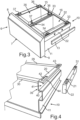
- FIG. 2 is an exploded view of the fresh-keeping container 6, as shown in Fig. 1 is shown.
- the two receiving trays 17 and 18 are shown in the removed state.
- the receiving tray 17 has a front flange 27 and a rear flange 28 on an upper edge 26.
- the receiving trough 17 with a rear wall 29 of the carrier trough 10 and a front edge 30 of the carrier trough 10 is suspended from above on these opposite flanges 27 and 28.
- the receiving trough 18 is designed accordingly.
- an actuating element 31 is arranged on the flange 20, which is preferably designed as an upwardly standing pin.
- a lid 32 ( Fig. 3 ) can be operated.
- the cover 32 can be moved relative to the associated receiving tray 18 and can thus be raised or lowered.
- the lid 32 comprises guide elements 33 and 34, which stand upwards on the side facing away from the receiving trough 18 and are hook-shaped.
- These guide elements 33 and 34 are mechanically coupled to guide webs arranged on the vertical inner sides of the interior 3. These guide webs are preferably not oriented horizontally, but rather inclined over a horizontal plane.
- the cover 32 is raised or lowered depending on the movement of the front wall 7 and the carrier trough 10 and thus also the receiving trough 18 inserted therein and is thus either completely placed on the receiving trough 18 or positioned slightly apart from it.
- the respective ambient humidity in the fresh-keeping container 16 and thus in the receiving volume formed by the receiving trough 18 and the lid 32 can be adjusted.
- the fresh-keeping container 15 also has a lid 35, which correspondingly comprises guide elements 36 and 37.
- the actuating element 31 is a pin 31 that can be displaced in the horizontal direction and thus in the depth direction and is oriented in the vertical direction and thus in the y direction, when the carrier trough 10 is inserted, a coupling can be made with a coupling element ( Fig. 5 ) and the cover 32 is then carried or pushed along by the corresponding movement. As a result, it is also moved via the guide elements 33 and 34 on the storage device formed by the guide webs and, due to its oblique orientation, the lid is thus arranged inclined or placed horizontally closed on the receiving tray 18.
- Pairs of opposing rear guide elements 33 and front guide elements 34 are provided, as is also the case with the cover 35. Also, in particular, like this Fig. 5 is shown, opposite actuating elements 31 are provided, which couple to opposite coupling elements 38.
- an arrangement of a guide part preferably oriented in the depth direction, is provided, which is then arranged virtually centrally between the covers 32 and 35, so that the corresponding storage of the cover 32 and the cover 35 is also provided here is.
- This can be, for example, a strut that is located on a front crossbar 44 ( Fig. 1 ) extends to a rear wall of the inner container 14 and is attached to each end.
- Fig. 4 the carrier tray 10 is shown in a partial perspective view.
- the side wall 11 is uneven and designed with a C-shape 39 in its upper region.
- a C-roof is formed by the flange 20 and a C-floor 40 is present opposite. This creates a receiving space 41 in which the setting unit 22 is arranged.
- a hole 42 is formed in the flange 20, through which the adjusting element 21 extends. Accordingly, a further hole 43 is formed through which the actuating element 31 extends.
- the flange 20 has an additional web 44 which is oriented downwards on its outwardly extending free end, so that the adjustment unit 22 is also held in position towards the outside in the inserted state in the receiving space 41.
- the front wall 7 is not shown.
- FIG. 6 The mechanical principle of operation is shown in a simplified side view.
- a coupling between the rotary movement or the actuation of the adjusting element 21 with the actuating element 31 is provided by the adjusting unit 22.
- the actuating element 31 is moved forward or backward in the adjusting unit 22 via a coupling device, in particular a coupling mechanism.
- the cover 32 is moved from its guide webs, in which the guide elements 33 and 34 are guided, in particular rest, via the coupling with coupling elements 38. There is thus a relative movement of the cover 32 to the receiving trough 18 caused by the adjusting element 21.
- the cover can then be raised or lowered, in which case the guide elements 33 and 34 are either within these notch-like receptacles are arranged and then the lid 32 rests completely closed on the receiving trough 18, or are arranged outside of these notch-like receptacles and the lid 32 is then raised upwards relative to the receiving trough 18 and no longer rests there in a fully closing manner.
- this actuating element 31 presses against the coupling element 38 during this pushing back and thus moves the entire cover 32 backwards, so that the guide elements 33 and 34 are guided along the guide webs and are lifted out of the notch-like receptacles.
Landscapes
- Engineering & Computer Science (AREA)
- Chemical & Material Sciences (AREA)
- Combustion & Propulsion (AREA)
- Physics & Mathematics (AREA)
- Mechanical Engineering (AREA)
- Thermal Sciences (AREA)
- General Engineering & Computer Science (AREA)
- Cold Air Circulating Systems And Constructional Details In Refrigerators (AREA)
- Packages (AREA)
- Devices That Are Associated With Refrigeration Equipment (AREA)
Applications Claiming Priority (1)
| Application Number | Priority Date | Filing Date | Title |
|---|---|---|---|
| DE102015222229.2A DE102015222229A1 (de) | 2015-11-11 | 2015-11-11 | Haushaltskältegerät mit einem Frischhaltebehälter, dessen Frontwand eine Außenwand des Geräts ist |
Publications (2)
| Publication Number | Publication Date |
|---|---|
| EP3168554A1 EP3168554A1 (de) | 2017-05-17 |
| EP3168554B1 true EP3168554B1 (de) | 2023-12-06 |
Family
ID=57133066
Family Applications (1)
| Application Number | Title | Priority Date | Filing Date |
|---|---|---|---|
| EP16193704.0A Active EP3168554B1 (de) | 2015-11-11 | 2016-10-13 | Haushaltskältegerät mit einem frischhaltebehälter, dessen frontwand eine aussenwand des geräts ist |
Country Status (5)
| Country | Link |
|---|---|
| US (1) | US9903635B2 (pl) |
| EP (1) | EP3168554B1 (pl) |
| CN (1) | CN206637934U (pl) |
| DE (1) | DE102015222229A1 (pl) |
| PL (1) | PL3168554T3 (pl) |
Families Citing this family (6)
| Publication number | Priority date | Publication date | Assignee | Title |
|---|---|---|---|---|
| DE102014218274A1 (de) * | 2014-09-12 | 2016-03-17 | BSH Hausgeräte GmbH | Haushaltskältegerät mit einem mit integrierter Anzeigeeinheit ausgebildetem Bedienelement zum Betätigen eines Deckels eines Frischhaltebehälters |
| TR201709671A2 (tr) * | 2017-06-30 | 2019-01-21 | Bsh Ev Aletleri San Ve Tic As | Kapi kapatma yardimcisina sahi̇p bi̇r soğutucu ci̇haz |
| US10342344B1 (en) | 2018-05-10 | 2019-07-09 | Prince Castle LLC | Refrigeration drawer organization insert |
| USD927635S1 (en) * | 2019-01-09 | 2021-08-10 | Lg Electronics Inc. | Water tank for indoor plant cultivator |
| USD928277S1 (en) * | 2019-12-31 | 2021-08-17 | Lg Electronics Inc. | Water tank for indoor plant cultivators |
| US11703267B2 (en) | 2021-07-12 | 2023-07-18 | Whirlpool Corporation | Refrigerator appliance |
Citations (1)
| Publication number | Priority date | Publication date | Assignee | Title |
|---|---|---|---|---|
| WO2015086185A1 (de) * | 2013-12-11 | 2015-06-18 | BSH Hausgeräte GmbH | Haushaltskältegerät mit einer feuchtigkeitsdicht abschliessenden kühlgutschublade |
Family Cites Families (40)
| Publication number | Priority date | Publication date | Assignee | Title |
|---|---|---|---|---|
| US2246342A (en) * | 1940-05-06 | 1941-06-17 | Joseph D Brown | Humidity drawer |
| US2724628A (en) * | 1951-03-20 | 1955-11-22 | Gibson Refrigerator Co | Refrigerator hydrator and movable cover |
| US2894845A (en) * | 1955-04-18 | 1959-07-14 | Gen Electric | Methods of preserving fresh foods |
| US2801146A (en) * | 1956-03-15 | 1957-07-30 | American Motors Corp | Refrigerating apparatus |
| JPH063341B2 (ja) * | 1986-06-02 | 1994-01-12 | 松下冷機株式会社 | 冷蔵庫 |
| US4850206A (en) * | 1988-11-18 | 1989-07-25 | Amana Refrigeration, Inc. | Crisper humidity control |
| DE4040341C2 (de) | 1990-12-17 | 1994-05-26 | Bosch Siemens Hausgeraete | Mit einem Deckel verschließbarer Behälter, insbesondere Frischhaltebox |
| KR930000044Y1 (ko) * | 1991-01-29 | 1993-01-09 | 삼성전자 주식회사 | 복합냉장고의 식품용기 수납장치 |
| US5417080A (en) * | 1992-07-09 | 1995-05-23 | Hydro-Crisper, Inc. | Vegetable crisper |
| WO1996004514A1 (en) * | 1994-08-03 | 1996-02-15 | Matsushita Refrigeration Company | Refrigerator |
| JP3559715B2 (ja) * | 1998-09-18 | 2004-09-02 | 株式会社東芝 | 冷蔵庫 |
| KR100469468B1 (ko) * | 2002-10-23 | 2005-02-02 | 엘지전자 주식회사 | 냉장고의 야채실 최적상태 보존 장치 |
| JP2004150763A (ja) * | 2002-10-31 | 2004-05-27 | Toshiba Corp | 冷蔵庫 |
| DE20313431U1 (de) * | 2003-08-29 | 2003-10-23 | BSH Bosch und Siemens Hausgeräte GmbH, 81669 München | Einsatzbehälter für ein Kältegerät |
| CN2731373Y (zh) * | 2004-09-06 | 2005-10-05 | 伊莱克斯(中国)电器有限公司 | 一种保鲜果菜盒 |
| DE102005036062A1 (de) * | 2005-08-01 | 2007-02-08 | BSH Bosch und Siemens Hausgeräte GmbH | Haushaltsgerät mit Sockel |
| US20070262686A1 (en) * | 2006-05-10 | 2007-11-15 | Lg Electronics Inc. | Refrigerator |
| KR20090106935A (ko) * | 2008-04-07 | 2009-10-12 | 엘지전자 주식회사 | 드로어커버를 구비한 냉장고 |
| KR100983151B1 (ko) * | 2008-06-23 | 2010-09-20 | 엘지전자 주식회사 | 조절부재를 구비한 냉장고 |
| DE102009002645A1 (de) * | 2009-04-24 | 2010-10-28 | BSH Bosch und Siemens Hausgeräte GmbH | Kältegerät mit Auszugkasten |
| EP2453190B1 (en) * | 2009-08-26 | 2016-03-30 | Panasonic Corporation | Refrigerator |
| DE102009029139A1 (de) | 2009-09-02 | 2011-03-03 | BSH Bosch und Siemens Hausgeräte GmbH | Kältegerät mit Gemüsefach |
| DE102009029141A1 (de) * | 2009-09-02 | 2011-03-03 | BSH Bosch und Siemens Hausgeräte GmbH | Kältegerät mit Gemüsefach |
| US8733122B2 (en) * | 2010-04-21 | 2014-05-27 | Samsung Electronics Co., Ltd. | Refrigerator having drawer |
| KR101631091B1 (ko) * | 2010-11-22 | 2016-06-17 | 삼성전자 주식회사 | 냉장고 및 그 저장용기 어셈블리 |
| US9127878B2 (en) * | 2011-01-31 | 2015-09-08 | Electrolux Home Products, Inc. | Tilt-out bin and removable crisper |
| KR20130098623A (ko) * | 2012-02-28 | 2013-09-05 | 삼성전자주식회사 | 저장유닛 및 이를 갖는 냉장고 |
| US20130300276A1 (en) * | 2012-05-08 | 2013-11-14 | General Electric Company | Drawer assembly for a refrigerator appliance |
| DE102012221499A1 (de) * | 2012-11-23 | 2014-05-28 | BSH Bosch und Siemens Hausgeräte GmbH | Haushaltskältegerät mit einem Anzeigemittel für einen Behälterdeckel |
| DE102012221496A1 (de) * | 2012-11-23 | 2014-05-28 | BSH Bosch und Siemens Hausgeräte GmbH | Haushaltskältegerät mit einem Betätigungsmittel für einen Behälterdeckel |
| US8960824B2 (en) * | 2013-03-15 | 2015-02-24 | Whirlpool Corporation | Customizable drawer liner for a refrigerator drawer |
| KR102028022B1 (ko) * | 2013-04-05 | 2019-10-04 | 삼성전자주식회사 | 냉장고 |
| US10365032B2 (en) * | 2013-07-29 | 2019-07-30 | Transform Sr Brands Llc | Slidable bin within a refrigerator drawer |
| US9353989B2 (en) * | 2013-10-12 | 2016-05-31 | Melody Ann Furr | Food storage system and method |
| DE102013225090A1 (de) * | 2013-12-06 | 2015-06-11 | BSH Hausgeräte GmbH | Haushaltskältegerät mit einem Frischhaltebehälter in einem Innenraum, der einen mit einem Bedienelement in einer Schublade anheb- und absenkbaren Deckel aufweist |
| KR101639135B1 (ko) * | 2014-11-28 | 2016-07-12 | 엘지전자 주식회사 | 수납 박스 어셈블리 및 이를 구비한 냉장고 |
| US20160153704A1 (en) * | 2014-12-02 | 2016-06-02 | Whirlpool Corporation | Multi-level drawer organization system for a refrigerating appliance |
| US9897370B2 (en) * | 2015-03-11 | 2018-02-20 | Whirlpool Corporation | Self-contained pantry box system for insertion into an appliance |
| US20160320118A1 (en) * | 2015-04-28 | 2016-11-03 | Whirlpool Corporation | Defrost chamber within freezer compartment |
| US9869506B2 (en) * | 2015-05-18 | 2018-01-16 | Electrolux Home Products, Inc. | Drawer system including cover |
-
2015
- 2015-11-11 DE DE102015222229.2A patent/DE102015222229A1/de not_active Withdrawn
-
2016
- 2016-10-13 PL PL16193704.0T patent/PL3168554T3/pl unknown
- 2016-10-13 EP EP16193704.0A patent/EP3168554B1/de active Active
- 2016-11-10 US US15/347,988 patent/US9903635B2/en not_active Expired - Fee Related
- 2016-11-10 CN CN201621211886.5U patent/CN206637934U/zh active Active
Patent Citations (1)
| Publication number | Priority date | Publication date | Assignee | Title |
|---|---|---|---|---|
| WO2015086185A1 (de) * | 2013-12-11 | 2015-06-18 | BSH Hausgeräte GmbH | Haushaltskältegerät mit einer feuchtigkeitsdicht abschliessenden kühlgutschublade |
Also Published As
| Publication number | Publication date |
|---|---|
| US9903635B2 (en) | 2018-02-27 |
| CN206637934U (zh) | 2017-11-14 |
| US20170131016A1 (en) | 2017-05-11 |
| DE102015222229A1 (de) | 2017-05-11 |
| PL3168554T3 (pl) | 2024-04-15 |
| EP3168554A1 (de) | 2017-05-17 |
Similar Documents
| Publication | Publication Date | Title |
|---|---|---|
| EP3168554B1 (de) | Haushaltskältegerät mit einem frischhaltebehälter, dessen frontwand eine aussenwand des geräts ist | |
| EP3285973B1 (de) | Aufbewahrungsbehälter | |
| EP3014202B1 (de) | Haushaltskältegerät mit einem frischhaltebehälter und einem bedienelement, das als push-push-verriegelungsmechanik zum bewegen eines deckels für den frischhaltebehälter ausgebildet ist | |
| EP3014203B1 (de) | Haushaltskältegerät mit einem frischhaltebehälter in einem innenraum, der einen mit einem drehbaren bedienelement anheb- und absenkbaren deckel aufweist | |
| EP3309485A1 (de) | Haushaltskältegerät mit einer in einer lagerposition mit spiel an einem auszugswagen angeordneten schale | |
| EP3798551B1 (de) | Lebensmittel-aufnahmebehälter mit tragschiene, in welcher eine klappe bewegbar gelagert ist, sowie haushaltskältegerät | |
| EP3309484B1 (de) | Haushaltskältegerät mit einem aufstellkorb für einen lebensmittelaufnahme-behälter | |
| DE102016219882A1 (de) | Haushaltskältegerät mit einer Auszugsvorrichtung mit einer mehrteiligen Sockelplatte und damit zusammensteckbaren Haltewinkeln | |
| EP2131125A2 (de) | Türablagefach für ein Kältegerät | |
| WO2015082279A1 (de) | Haushaltskältegerät mit einem frischhaltebehälter in einem innenraum, der einen mit einem bedienelement in einer schublade anheb- und absenkbaren deckel aufweist | |
| DE202006012656U1 (de) | Schrank mit einem Auszugsteil | |
| DE102015203835B4 (de) | Haushaltskältegerät mit einem spezifischen Auszugswagen | |
| EP2005093B1 (de) | Kältegerät mit abstellplatte | |
| EP1916924B1 (de) | Schrank mit einem auszugsteil | |
| EP2192363B1 (de) | Kühl- und/oder Gefriergerät | |
| EP3798546B1 (de) | Lebensmittel-aufnahmebehälter mit spezifisch geformter klappe einer lüftungseinrichtung, sowie haushaltskältegerät | |
| EP3014204B1 (de) | Haushaltskältegerät mit einem frischhaltebehälter und einem bedienelement und einer bewegungsführungseinrichtung | |
| EP3014199B1 (de) | Haushaltskältegerät mit einem innenraum und einem frischhaltebehälter mit einem deckel mit nach vorne offener führungsbahn | |
| DE102008029031A1 (de) | Kältegerät | |
| EP4086546B1 (de) | Lebensmittel-aufnahmebehälter mit einer klimatisierungsvorrichtung mit spezifischer verstellung zwischen einer schale und einem aufsatz, sowie haushaltskältegerät | |
| DE20120242U1 (de) | Bodenseitiger Schubkasten für ein Stellmöbel | |
| EP3546867A1 (de) | Auszugsvorrichtung für ein haushaltskältegerät, mit in unterschiedlichen ebenen angeordneten lebensmittel-lagereinheiten, die mittels eines griffelements definiert entkoppelbar sind, sowie haushaltskältegerät | |
| WO2015082282A1 (de) | Haushaltskältegerät mit einem im innenraum verschiebbar angeordneten trägerschlitten | |
| DE20116861U1 (de) | Vorrichtung zur Aufnahme von Dosen, insbesondere Gewürzdosen, Gläsern u.ä. Teilen aus Küche und Bad | |
| EP3798549A1 (de) | Lebensmittel-aufnahmebehälter mit schale und spezifischem deckel dazu, sowie haushaltskältegerät |
Legal Events
| Date | Code | Title | Description |
|---|---|---|---|
| PUAI | Public reference made under article 153(3) epc to a published international application that has entered the european phase |
Free format text: ORIGINAL CODE: 0009012 |
|
| STAA | Information on the status of an ep patent application or granted ep patent |
Free format text: STATUS: THE APPLICATION HAS BEEN PUBLISHED |
|
| AK | Designated contracting states |
Kind code of ref document: A1 Designated state(s): AL AT BE BG CH CY CZ DE DK EE ES FI FR GB GR HR HU IE IS IT LI LT LU LV MC MK MT NL NO PL PT RO RS SE SI SK SM TR |
|
| AX | Request for extension of the european patent |
Extension state: BA ME |
|
| STAA | Information on the status of an ep patent application or granted ep patent |
Free format text: STATUS: REQUEST FOR EXAMINATION WAS MADE |
|
| 17P | Request for examination filed |
Effective date: 20171117 |
|
| RBV | Designated contracting states (corrected) |
Designated state(s): AL AT BE BG CH CY CZ DE DK EE ES FI FR GB GR HR HU IE IS IT LI LT LU LV MC MK MT NL NO PL PT RO RS SE SI SK SM TR |
|
| STAA | Information on the status of an ep patent application or granted ep patent |
Free format text: STATUS: EXAMINATION IS IN PROGRESS |
|
| 17Q | First examination report despatched |
Effective date: 20190926 |
|
| GRAP | Despatch of communication of intention to grant a patent |
Free format text: ORIGINAL CODE: EPIDOSNIGR1 |
|
| STAA | Information on the status of an ep patent application or granted ep patent |
Free format text: STATUS: GRANT OF PATENT IS INTENDED |
|
| INTG | Intention to grant announced |
Effective date: 20230619 |
|
| GRAS | Grant fee paid |
Free format text: ORIGINAL CODE: EPIDOSNIGR3 |
|
| GRAA | (expected) grant |
Free format text: ORIGINAL CODE: 0009210 |
|
| STAA | Information on the status of an ep patent application or granted ep patent |
Free format text: STATUS: THE PATENT HAS BEEN GRANTED |
|
| AK | Designated contracting states |
Kind code of ref document: B1 Designated state(s): AL AT BE BG CH CY CZ DE DK EE ES FI FR GB GR HR HU IE IS IT LI LT LU LV MC MK MT NL NO PL PT RO RS SE SI SK SM TR |
|
| REG | Reference to a national code |
Ref country code: GB Ref legal event code: FG4D Free format text: NOT ENGLISH |
|
| REG | Reference to a national code |
Ref country code: CH Ref legal event code: EP |
|
| REG | Reference to a national code |
Ref country code: DE Ref legal event code: R096 Ref document number: 502016016256 Country of ref document: DE |
|
| REG | Reference to a national code |
Ref country code: IE Ref legal event code: FG4D Free format text: LANGUAGE OF EP DOCUMENT: GERMAN |
|
| REG | Reference to a national code |
Ref country code: LT Ref legal event code: MG9D |
|
| PG25 | Lapsed in a contracting state [announced via postgrant information from national office to epo] |
Ref country code: GR Free format text: LAPSE BECAUSE OF FAILURE TO SUBMIT A TRANSLATION OF THE DESCRIPTION OR TO PAY THE FEE WITHIN THE PRESCRIBED TIME-LIMIT Effective date: 20240307 |
|
| REG | Reference to a national code |
Ref country code: NL Ref legal event code: MP Effective date: 20231206 |
|
| PG25 | Lapsed in a contracting state [announced via postgrant information from national office to epo] |
Ref country code: LT Free format text: LAPSE BECAUSE OF FAILURE TO SUBMIT A TRANSLATION OF THE DESCRIPTION OR TO PAY THE FEE WITHIN THE PRESCRIBED TIME-LIMIT Effective date: 20231206 |
|
| PG25 | Lapsed in a contracting state [announced via postgrant information from national office to epo] |
Ref country code: ES Free format text: LAPSE BECAUSE OF FAILURE TO SUBMIT A TRANSLATION OF THE DESCRIPTION OR TO PAY THE FEE WITHIN THE PRESCRIBED TIME-LIMIT Effective date: 20231206 |
|
| PG25 | Lapsed in a contracting state [announced via postgrant information from national office to epo] |
Ref country code: LT Free format text: LAPSE BECAUSE OF FAILURE TO SUBMIT A TRANSLATION OF THE DESCRIPTION OR TO PAY THE FEE WITHIN THE PRESCRIBED TIME-LIMIT Effective date: 20231206 Ref country code: GR Free format text: LAPSE BECAUSE OF FAILURE TO SUBMIT A TRANSLATION OF THE DESCRIPTION OR TO PAY THE FEE WITHIN THE PRESCRIBED TIME-LIMIT Effective date: 20240307 Ref country code: ES Free format text: LAPSE BECAUSE OF FAILURE TO SUBMIT A TRANSLATION OF THE DESCRIPTION OR TO PAY THE FEE WITHIN THE PRESCRIBED TIME-LIMIT Effective date: 20231206 Ref country code: BG Free format text: LAPSE BECAUSE OF FAILURE TO SUBMIT A TRANSLATION OF THE DESCRIPTION OR TO PAY THE FEE WITHIN THE PRESCRIBED TIME-LIMIT Effective date: 20240306 |
|
| PG25 | Lapsed in a contracting state [announced via postgrant information from national office to epo] |
Ref country code: NL Free format text: LAPSE BECAUSE OF FAILURE TO SUBMIT A TRANSLATION OF THE DESCRIPTION OR TO PAY THE FEE WITHIN THE PRESCRIBED TIME-LIMIT Effective date: 20231206 |
|
| PG25 | Lapsed in a contracting state [announced via postgrant information from national office to epo] |
Ref country code: SE Free format text: LAPSE BECAUSE OF FAILURE TO SUBMIT A TRANSLATION OF THE DESCRIPTION OR TO PAY THE FEE WITHIN THE PRESCRIBED TIME-LIMIT Effective date: 20231206 Ref country code: RS Free format text: LAPSE BECAUSE OF FAILURE TO SUBMIT A TRANSLATION OF THE DESCRIPTION OR TO PAY THE FEE WITHIN THE PRESCRIBED TIME-LIMIT Effective date: 20231206 Ref country code: NO Free format text: LAPSE BECAUSE OF FAILURE TO SUBMIT A TRANSLATION OF THE DESCRIPTION OR TO PAY THE FEE WITHIN THE PRESCRIBED TIME-LIMIT Effective date: 20240306 Ref country code: NL Free format text: LAPSE BECAUSE OF FAILURE TO SUBMIT A TRANSLATION OF THE DESCRIPTION OR TO PAY THE FEE WITHIN THE PRESCRIBED TIME-LIMIT Effective date: 20231206 Ref country code: LV Free format text: LAPSE BECAUSE OF FAILURE TO SUBMIT A TRANSLATION OF THE DESCRIPTION OR TO PAY THE FEE WITHIN THE PRESCRIBED TIME-LIMIT Effective date: 20231206 Ref country code: HR Free format text: LAPSE BECAUSE OF FAILURE TO SUBMIT A TRANSLATION OF THE DESCRIPTION OR TO PAY THE FEE WITHIN THE PRESCRIBED TIME-LIMIT Effective date: 20231206 |
|
| PG25 | Lapsed in a contracting state [announced via postgrant information from national office to epo] |
Ref country code: IS Free format text: LAPSE BECAUSE OF FAILURE TO SUBMIT A TRANSLATION OF THE DESCRIPTION OR TO PAY THE FEE WITHIN THE PRESCRIBED TIME-LIMIT Effective date: 20240406 |
|
| PG25 | Lapsed in a contracting state [announced via postgrant information from national office to epo] |
Ref country code: CZ Free format text: LAPSE BECAUSE OF FAILURE TO SUBMIT A TRANSLATION OF THE DESCRIPTION OR TO PAY THE FEE WITHIN THE PRESCRIBED TIME-LIMIT Effective date: 20231206 |
|
| PG25 | Lapsed in a contracting state [announced via postgrant information from national office to epo] |
Ref country code: SK Free format text: LAPSE BECAUSE OF FAILURE TO SUBMIT A TRANSLATION OF THE DESCRIPTION OR TO PAY THE FEE WITHIN THE PRESCRIBED TIME-LIMIT Effective date: 20231206 |
|
| PG25 | Lapsed in a contracting state [announced via postgrant information from national office to epo] |
Ref country code: SM Free format text: LAPSE BECAUSE OF FAILURE TO SUBMIT A TRANSLATION OF THE DESCRIPTION OR TO PAY THE FEE WITHIN THE PRESCRIBED TIME-LIMIT Effective date: 20231206 Ref country code: SK Free format text: LAPSE BECAUSE OF FAILURE TO SUBMIT A TRANSLATION OF THE DESCRIPTION OR TO PAY THE FEE WITHIN THE PRESCRIBED TIME-LIMIT Effective date: 20231206 Ref country code: RO Free format text: LAPSE BECAUSE OF FAILURE TO SUBMIT A TRANSLATION OF THE DESCRIPTION OR TO PAY THE FEE WITHIN THE PRESCRIBED TIME-LIMIT Effective date: 20231206 Ref country code: IT Free format text: LAPSE BECAUSE OF FAILURE TO SUBMIT A TRANSLATION OF THE DESCRIPTION OR TO PAY THE FEE WITHIN THE PRESCRIBED TIME-LIMIT Effective date: 20231206 Ref country code: IS Free format text: LAPSE BECAUSE OF FAILURE TO SUBMIT A TRANSLATION OF THE DESCRIPTION OR TO PAY THE FEE WITHIN THE PRESCRIBED TIME-LIMIT Effective date: 20240406 Ref country code: EE Free format text: LAPSE BECAUSE OF FAILURE TO SUBMIT A TRANSLATION OF THE DESCRIPTION OR TO PAY THE FEE WITHIN THE PRESCRIBED TIME-LIMIT Effective date: 20231206 Ref country code: CZ Free format text: LAPSE BECAUSE OF FAILURE TO SUBMIT A TRANSLATION OF THE DESCRIPTION OR TO PAY THE FEE WITHIN THE PRESCRIBED TIME-LIMIT Effective date: 20231206 |
|
| PG25 | Lapsed in a contracting state [announced via postgrant information from national office to epo] |
Ref country code: PT Free format text: LAPSE BECAUSE OF FAILURE TO SUBMIT A TRANSLATION OF THE DESCRIPTION OR TO PAY THE FEE WITHIN THE PRESCRIBED TIME-LIMIT Effective date: 20240408 |
|
| PG25 | Lapsed in a contracting state [announced via postgrant information from national office to epo] |
Ref country code: PT Free format text: LAPSE BECAUSE OF FAILURE TO SUBMIT A TRANSLATION OF THE DESCRIPTION OR TO PAY THE FEE WITHIN THE PRESCRIBED TIME-LIMIT Effective date: 20240408 |
|
| REG | Reference to a national code |
Ref country code: DE Ref legal event code: R097 Ref document number: 502016016256 Country of ref document: DE |
|
| PG25 | Lapsed in a contracting state [announced via postgrant information from national office to epo] |
Ref country code: DK Free format text: LAPSE BECAUSE OF FAILURE TO SUBMIT A TRANSLATION OF THE DESCRIPTION OR TO PAY THE FEE WITHIN THE PRESCRIBED TIME-LIMIT Effective date: 20231206 |
|
| PLBE | No opposition filed within time limit |
Free format text: ORIGINAL CODE: 0009261 |
|
| STAA | Information on the status of an ep patent application or granted ep patent |
Free format text: STATUS: NO OPPOSITION FILED WITHIN TIME LIMIT |
|
| PG25 | Lapsed in a contracting state [announced via postgrant information from national office to epo] |
Ref country code: SI Free format text: LAPSE BECAUSE OF FAILURE TO SUBMIT A TRANSLATION OF THE DESCRIPTION OR TO PAY THE FEE WITHIN THE PRESCRIBED TIME-LIMIT Effective date: 20231206 |
|
| PG25 | Lapsed in a contracting state [announced via postgrant information from national office to epo] |
Ref country code: SI Free format text: LAPSE BECAUSE OF FAILURE TO SUBMIT A TRANSLATION OF THE DESCRIPTION OR TO PAY THE FEE WITHIN THE PRESCRIBED TIME-LIMIT Effective date: 20231206 Ref country code: DK Free format text: LAPSE BECAUSE OF FAILURE TO SUBMIT A TRANSLATION OF THE DESCRIPTION OR TO PAY THE FEE WITHIN THE PRESCRIBED TIME-LIMIT Effective date: 20231206 |
|
| 26N | No opposition filed |
Effective date: 20240909 |
|
| PGFP | Annual fee paid to national office [announced via postgrant information from national office to epo] |
Ref country code: DE Payment date: 20241031 Year of fee payment: 9 |
|
| PGFP | Annual fee paid to national office [announced via postgrant information from national office to epo] |
Ref country code: PL Payment date: 20241001 Year of fee payment: 9 |
|
| PGFP | Annual fee paid to national office [announced via postgrant information from national office to epo] |
Ref country code: TR Payment date: 20241002 Year of fee payment: 9 |
|
| REG | Reference to a national code |
Ref country code: CH Ref legal event code: PL |
|
| GBPC | Gb: european patent ceased through non-payment of renewal fee |
Effective date: 20241013 |
|
| PG25 | Lapsed in a contracting state [announced via postgrant information from national office to epo] |
Ref country code: MC Free format text: LAPSE BECAUSE OF FAILURE TO SUBMIT A TRANSLATION OF THE DESCRIPTION OR TO PAY THE FEE WITHIN THE PRESCRIBED TIME-LIMIT Effective date: 20231206 |
|
| PG25 | Lapsed in a contracting state [announced via postgrant information from national office to epo] |
Ref country code: GB Free format text: LAPSE BECAUSE OF NON-PAYMENT OF DUE FEES Effective date: 20241013 |
|
| PG25 | Lapsed in a contracting state [announced via postgrant information from national office to epo] |
Ref country code: BE Free format text: LAPSE BECAUSE OF NON-PAYMENT OF DUE FEES Effective date: 20241031 Ref country code: LU Free format text: LAPSE BECAUSE OF NON-PAYMENT OF DUE FEES Effective date: 20241013 |
|
| PG25 | Lapsed in a contracting state [announced via postgrant information from national office to epo] |
Ref country code: FR Free format text: LAPSE BECAUSE OF NON-PAYMENT OF DUE FEES Effective date: 20241031 |
|
| PG25 | Lapsed in a contracting state [announced via postgrant information from national office to epo] |
Ref country code: CH Free format text: LAPSE BECAUSE OF NON-PAYMENT OF DUE FEES Effective date: 20241031 |
|
| REG | Reference to a national code |
Ref country code: BE Ref legal event code: MM Effective date: 20241031 |
|
| PG25 | Lapsed in a contracting state [announced via postgrant information from national office to epo] |
Ref country code: FI Free format text: LAPSE BECAUSE OF FAILURE TO SUBMIT A TRANSLATION OF THE DESCRIPTION OR TO PAY THE FEE WITHIN THE PRESCRIBED TIME-LIMIT Effective date: 20231207 |
|
| PG25 | Lapsed in a contracting state [announced via postgrant information from national office to epo] |
Ref country code: IE Free format text: LAPSE BECAUSE OF NON-PAYMENT OF DUE FEES Effective date: 20241013 |
|
| REG | Reference to a national code |
Ref country code: AT Ref legal event code: MM01 Ref document number: 1638776 Country of ref document: AT Kind code of ref document: T Effective date: 20241013 |
|
| PG25 | Lapsed in a contracting state [announced via postgrant information from national office to epo] |
Ref country code: AT Free format text: LAPSE BECAUSE OF NON-PAYMENT OF DUE FEES Effective date: 20241013 |
|
| PG25 | Lapsed in a contracting state [announced via postgrant information from national office to epo] |
Ref country code: CY Free format text: LAPSE BECAUSE OF FAILURE TO SUBMIT A TRANSLATION OF THE DESCRIPTION OR TO PAY THE FEE WITHIN THE PRESCRIBED TIME-LIMIT; INVALID AB INITIO Effective date: 20161013 |
|
| PG25 | Lapsed in a contracting state [announced via postgrant information from national office to epo] |
Ref country code: HU Free format text: LAPSE BECAUSE OF FAILURE TO SUBMIT A TRANSLATION OF THE DESCRIPTION OR TO PAY THE FEE WITHIN THE PRESCRIBED TIME-LIMIT; INVALID AB INITIO Effective date: 20161013 |