EP3165696B1 - Serrure comprenant un fouillot débrayable - Google Patents
Serrure comprenant un fouillot débrayable Download PDFInfo
- Publication number
- EP3165696B1 EP3165696B1 EP16194131.5A EP16194131A EP3165696B1 EP 3165696 B1 EP3165696 B1 EP 3165696B1 EP 16194131 A EP16194131 A EP 16194131A EP 3165696 B1 EP3165696 B1 EP 3165696B1
- Authority
- EP
- European Patent Office
- Prior art keywords
- lock
- follower
- latch
- coupling
- nut
- Prior art date
- Legal status (The legal status is an assumption and is not a legal conclusion. Google has not performed a legal analysis and makes no representation as to the accuracy of the status listed.)
- Active
Links
- 230000008878 coupling Effects 0.000 claims description 41
- 238000010168 coupling process Methods 0.000 claims description 41
- 238000005859 coupling reaction Methods 0.000 claims description 41
- 230000000903 blocking effect Effects 0.000 description 2
- 230000000295 complement effect Effects 0.000 description 1
- 231100001261 hazardous Toxicity 0.000 description 1
- 238000009434 installation Methods 0.000 description 1
Images


Classifications
-
- E—FIXED CONSTRUCTIONS
- E05—LOCKS; KEYS; WINDOW OR DOOR FITTINGS; SAFES
- E05B—LOCKS; ACCESSORIES THEREFOR; HANDCUFFS
- E05B65/00—Locks or fastenings for special use
- E05B65/10—Locks or fastenings for special use for panic or emergency doors
- E05B65/1086—Locks with panic function, e.g. allowing opening from the inside without a ley even when locked from the outside
-
- E—FIXED CONSTRUCTIONS
- E05—LOCKS; KEYS; WINDOW OR DOOR FITTINGS; SAFES
- E05B—LOCKS; ACCESSORIES THEREFOR; HANDCUFFS
- E05B13/00—Devices preventing the key or the handle or both from being used
- E05B13/005—Disconnecting the handle
-
- E—FIXED CONSTRUCTIONS
- E05—LOCKS; KEYS; WINDOW OR DOOR FITTINGS; SAFES
- E05B—LOCKS; ACCESSORIES THEREFOR; HANDCUFFS
- E05B15/00—Other details of locks; Parts for engagement by bolts of fastening devices
- E05B15/0013—Followers; Bearings therefor
-
- E—FIXED CONSTRUCTIONS
- E05—LOCKS; KEYS; WINDOW OR DOOR FITTINGS; SAFES
- E05B—LOCKS; ACCESSORIES THEREFOR; HANDCUFFS
- E05B63/00—Locks or fastenings with special structural characteristics
- E05B63/16—Locks or fastenings with special structural characteristics with the handles on opposite sides moving independently
Definitions
- the invention relates to a lock for a door or a window or the like according to the features of the preamble of claim 1.
- panic locks are often used to secure building access. These are locks that secure access to a building from the outside and at the same time allow you to leave the building from the inside at any time. In the event of an emergency or panic, the building can be left at any time.
- a generic lock is from the DE43 19 325 A1 known.
- a panic lock with a two-part lock nut is described.
- the outer nut can be coupled via a spring-loaded nut lever.
- the nut lever is mounted on the inner nut and has a nose that engages in a shoulder of the outer nut for coupling. This clutch remains when the nut is actuated.
- Another panic lock is out of the DE 10 2012 010 786 A1 known.
- a mortise lock with a lock bolt received in a lock housing and a three-part lock nut which interacts with a door handle.
- the lock nut is constructed in three parts, with a center nut being permanently connected to the lock mechanism and via one Coupling device either an outer nut part or an inner nut part can be coupled or uncoupled.
- a nut driver is designed as a driver lever acting directly between the outer nut and the inner nut, which is either pivotally mounted on one end on the outer nut and is supported on the other side on a support bearing arranged on the inner nut, or is pivotably supported on the inner nut at one end and is mounted on the other is supported on a support bearing arranged on the outer nut, and the driver lever uncouples the outer nut from the inner nut by a spring pivoting the driver lever into a position out of engagement with the support bearing, by the contour of the support bearing and / or the end of the driver lever cooperating with the support bearing has a beveled support surface which urges the driver lever out of engagement when the outside handle is actuated.
- the driver lever points, so to speak a preferred position in which the outer nut is separated from the inner nut.
- the device according to the invention enables the outside handle to be safely uncoupled.
- the lock according to the invention enables the space to be secured to be securely closed even in the event of a danger situation caused by a killing spree.
- the lock mechanism is prevented from jamming by actuating the lock mechanism to uncouple the outer nut.
- the external handle can be uncoupled, for example, by actuating a locking cylinder accommodated in the lock in the closing direction.
- the locking cylinder can be operated in the opening direction for coupling.
- the lock cylinder can interact with a control element or control slide mounted within the lock housing in order to control the uncoupling or the coupling.
- inside refers to the side of a door that lies in a secure room, for example a classroom in a school.
- the outside refers to the outside of a secured room, for example a hallway or an outside area of a building.
- the lock has a lock faceplate and a lock case connected to it.
- a receptacle for a lock cylinder Arranged in the lock case are a receptacle for a lock cylinder, a detachable lock nut, a latch or a latch bolt, and a control element which can be switched by a lock cylinder between a decoupled position and a coupled position.
- the detachable lock nut has an inner nut that can be connected or connected to an inner handle and an outer nut that can be connected to an outer handle.
- the control element interacts with a coupling element in order to couple and / or uncouple the outer nut.
- the lock nut is designed as a two-part nut and has an inner nut and an outer nut. A nut middle part is not necessary.
- the inner nut can be permanently connected to the lock mechanism to enable the lock to be operated at any time by the inside handle.
- the inner nut can also be designed as a detachable nut part in order to selectively couple the inner handle, i.e. to connect with the lock mechanism, or to disconnect i.e. separate from the lock mechanism.
- control element is designed as a control element which can be displaced and / or pivoted transversely to the lock faceplate.
- the control element is bistable, i.e. it can be specifically switched between the uncoupled or the engaged position. This means that the control element has a stable position both in the uncoupled position and also has a stable position in the coupled position.
- the control element is preferably completely accommodated within the lock housing.
- control element has a recess into which a resilient catch engages in the engaged position in order to fix the engaged position of the control element.
- control element has a second recess into which one is in the disengaged position spring catch engages to fix the disengaged position of the control.
- control element is designed as a control slide which is slidably mounted in the lock case via a link guide or via an elongated hole cooperating with a pin.
- a safe guidance of the control element is made possible via a link guide or an elongated hole with a pin, without the control element being able to jam or get caught in an intermediate position.
- the control element actuates a coupling element which interacts with the driving lever for coupling or uncoupling the outer nut.
- the coupling element is designed as a coupling slide that can be moved parallel to the faceplate, one end of which cooperates directly with the driving lever and the other end directly with the control lever.
- the end of the coupling element interacting with the driving lever has a support surface or drainage surface, the contour of which is adapted to a round contour of the lock nut.
- the driver lever is supported in the engaged position on the support surface or drainage surface in order to prevent the outer nut from being uncoupled.
- the driver lever is pushed into the engaged position by the support surface or drain surface.
- the coupling element interacts with the driver lever in such a way that it remains securely coupled in the engaged position and thus prevents the outer nut from being uncoupled.
- the drainage surface or support surface extends over a circular section which is the same size or larger than the maximum rotation angle of the lock nut, preferably covering a circular section in the range of a rotation angle of 15 ° to 70 °.
- the coupling element thus has, so to speak, a slide bearing on which the driver lever slides, which ensures uniform support of the driver lever over the entire range of rotation of the lock nut and thereby ensures that the outer nut remains in the engaged position.
- the coupling element is connected to a coupling spring mounted in the lock case, which acts on the coupling element in the uncoupled position the movement path of the driver lever is led out.
- a coupling spring mounted in the lock case acts on the coupling element in the uncoupled position the movement path of the driver lever is led out.
- the coupling element is designed as a coupling slide, which is displaceably mounted parallel to the faceplate is.
- this means that the coupling slide is not only spring-loaded, but also supported by its weight force in the uncoupled position. This enables a particularly safe disengagement of the lock.
- control element interacts with the coupling element via a bevelled guide surface in order to displace it against the force of the coupling spring for coupling.
- the inner nut is permanently coupled to the trap or a trap mechanism actuating the trap.
- the latch is designed as a lockable latch or as a latch bolt.
- the trap can be designed, for example, as a cross trap or as a tilt trap.
- the trap can also be designed as a so-called shooting trap that excludes spring-loaded from the lock housing. It is thereby achieved that when the door is closed, the lock automatically keeps the door in the closed position via the latch, and access to the secured space is therefore no longer possible, at least from the outside.
- the latch can be locked, ie it cannot be pushed back into the lock housing even in the event of a mechanical attack on the latch.
- the lock case has a change in order to unlock and / or withdraw the latch both via the lock cylinder and via a door handle.
- the change it is possible to open the lock from the outside as well as from the inside by means of a locking cylinder. An authorized person can therefore enter the secure room from the outside at any time using a key.
- a lock cylinder is accommodated in the lock cylinder receptacle, which can be actuated from the inside via an inside handle, preferably a rotary knob, and from the outside via a key.
- the lock cylinder does not actuate a lock bolt. It primarily controls the uncoupling or uncoupling of the outer nut or the outer handle.
- the locking cylinder has a slip clutch in order to separate the inside handle in the event of a blockage.
- the slip clutch prevents access to the secured space from being blocked from the inside, for example by blocking the handle of the locking cylinder.
- the slip clutch enables the lock to be opened from the outside even if the handle is blocked on the inside.
- the lock has no dead bolt.
- many components of the Lock mechanism which could otherwise possibly cause the latch mechanism and / or the lock nut to become blocked or jammed.
- a fixing or blocking of the driver lever by means of a screw is not possible in the lock according to the invention, in order to enable the outer nut to be uncoupled at any time.
- the Figures 1-5 show a possible embodiment of the lock 1.
- the same parts of the lock are each provided with the same reference numerals.
- the Fig. 1 shows a schematic view of the lock 1 according to the invention installed in a wing of a door in a building.
- the lock 1 is designed as a mortise lock and sits in a tab of the door leaf.
- the lock is connected to two door handles, on the inside of the secured room with an interior door handle 7i and on the Outside with an outside door handle 7a.
- a locking cylinder 6 is accommodated in a locking cylinder receptacle of the lock 1 and can be operated from the inside by means of a rotary knob 61.
- the lock 1 In a starting position, the lock 1 can be operated and opened from both sides using the lever handle. If required, the outside door handle 7a can be uncoupled from the inside, ie from the secured space. Uncoupling is done by turning the hand knob 61, as in Fig. 1 shown in the direction of the arrow. This makes it possible to lock the lock 1 from the secured room in such a way that the door cannot be opened from the outside. Uncoupling the outside door handle 7a is also possible especially when the outside door handle 7a has already been actuated.
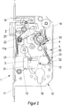
- the lock 1 is shown with the lock cover removed.
- the lock has a lock case 12 and a lock face plate 11.
- Arranged in the lock case 12 are the elements of the lock mechanism as well as a latch 2 reaching through the face plate and a control latch 16 reaching through the face plate.
- the lock case 12 has in its lower area a receptacle 18 for a lock cylinder, not shown.
- a lock nut 4 is arranged above the locking cylinder.
- the lock nut 4 is designed as a split lock nut and has, as in Fig. 5 shown, an inner nut 4i and an outer nut 4a.
- a door handle can be inserted into the lock nut 4 by means of a handle pin.
- a spiral spring 14 is arranged in the lock case 12 above the lock nut 4 and serves as a return spring for the lever handle.
- the lock nut 4 has a latch driver 44 which interacts with the latch 2 in order to withdraw them into the lock housing 12 for unlocking.
- the latch 2 is designed as a shooting latch and is acted upon or pushed out of the lock housing 12 by a latch spring 21.
- a control latch 16 is arranged above the lock latch 2.
- the control latch 16 interacts with a latch locking mechanism in order to lock the latch 2 when the door is locked.
- the latch locking mechanism has a slide plate which can be moved parallel to the faceplate and which is used to lock the latch downwards, ie into the in Fig. 2 position shown is movable.
- a front edge of the slide plate is on the rear side of the latch body and prevents the latch 2 from being pressed back into the lock housing 12. A secure locking in the closed position of the door to
- the lock 1 can be unlocked, for example, via a locking cylinder inserted into the locking cylinder receptacle 18.
- a change lever 17 is actuated, by means of which the slide plate 22 is moved upward parallel to the face plate and thereby releases the latch 2.
- the change lever 17 pulls the latch 2 back into the lock housing 12 via a pivot lever 17a.
- An alternative way of opening the lock 1 is via the inside door handle 7i.
- the door handle 7i is connected to the inner nut 4i.
- the inner nut 4i is rotated clockwise.
- the slide plate 22 is lifted by a cam of the inner nut and at the same time the latch 2 is retracted into the lock housing 12 via the latch driver 44.
- the lock can also be opened from the outside via the door handle 7a connected to the outer nut 4a.
- the lock nut 4 is in the Fig. 4 shown as an assembly.
- the lock nut 4 has a receptacle for a handle pin in the middle.
- the inside 4i of the lock nut is permanently connected to the lock mechanism in order to actuate the latch 2.
- the outer nut 4a of the two-part lock nut 4 can optionally be connected or disconnected.
- a nut driver 41 arranged between the outer nut part 4a and the inner nut part 4i is provided for coupling or uncoupling the outer nut part 4a.
- the nut driver 41 is pivotally mounted on the outer nut part 4a.
- the outer nut part 4a has a pin which engages in a bore in the nut driver 41.
- the pin forms a pivot bearing for the nut driver lever 41.
- a driver spring 42 is arranged in the area of the pivot bearing.
- the driver spring 42 acts on the nut driver 41 to the outside, ie out of the lock nut 4.
- the engaged position of the nut driver 41 is shown.
- the nut driver 41 In the coupled position, the nut driver 41 is supported on the support bearing 43 on the inner nut 4i.
- the outer nut 4a is connected in a rotationally fixed manner to the inner nut 4i via the driving lever 41.
- the driver lever 41 has a bevelled outer contour in the region of the support bearing, which is designed such that the driver lever 41 is forced out of engagement with the support bearing 43 by the rotation of the outer nut 4a.
- the lock is shown with the outer nut engaged.
- the lock 1 has a cross mounted to the faceplate 11 slidably Control spool 3 on.
- the control slide 3 is slidably mounted in the lock housing 12 via an elongated hole 32 and a pin 15.
- the spool 3 points at its in the Fig. 2 right end on a guide surface 33 which is inclined and cooperates with a clutch slide 5.
- the clutch slide 5 is supported against the force of the clutch spring 52 on the top of the control slide 3.
- the control slide 3 is fixed in this engaged position by a resilient catch 13.
- the resilient catch 13 engages in a recess 31 arranged on the control slide 3.
- the clutch slide 5 cooperates at its upper end with the nut driver 41.
- the clutch slide 5 has a drain surface 51 at its upper end.
- the drain surface 51 is rounded and complementary to the round lock nut 4.
- the nut driver 41 is supported on the drain surface, which in turn urges the nut driver 41 against the force of the driver spring 42 against the lock nut 4 to engage it.
- the driver lever 41 in the Fig. 2 or 4 shown coupled position fixed.
- the round design of the run-off surface 51 ensures that the engagement of the follower lever 41 with the support bearing 43 is ensured over the entire rotation angle range of the lock nut.
- the lock is shown in the uncoupled position of the outer nut 4a.
- the control slide 3 is shifted to the left, ie towards the face plate 11.
- the control spool 3 is displaced via a locking cylinder (not shown).
- the locking cylinder is inserted in the locking cylinder receptacle 18 and engages with its locking lug in a recess in the control slide.
- When closing ie when Turning the lock cylinder counterclockwise moves the control spool 3 to the left.
- the coupling element 5 acted upon by the coupling spring 52 slides along the inclined guide surface 33.
- the upper end of the coupling element 5 moves away from the lock nut 4.
- the guide surface 51 releases the driver lever 41.
- the driver spring 42 pivots the driver lever 41 about its pivot bearing so that it disengages from the support bearing 43.
- the rotationally fixed connection between the outer nut part 4a and the inner nut part 4i is canceled, so that the outer nut part 4a can rotate freely.
- the connection of the outside door handle 7a with the lock mechanism is released, so that the lock 1 can no longer be opened from the outside.
- Uncoupling the outer door nut 4a is possible in any position of the lock nut 4 or the inner nut part or the outer nut part. Even if the outside door handle is already actuated, it is ensured that the driving lever 41 is pressed out of engagement via the driving spring 42 and thus the outer nut part 4a is uncoupled. Even if, in an emergency, the inside door handle 7a is held against an opening force applied from the outside, i.e. an increased clamping force occurs, the oblique contour of the driving lever 41 ensures that it is disengaged from the support bearing 43 and the outside nut 4a is securely removed the inner nut 4i uncouples. This means that the door can be locked securely in any situation from within a secured room.
Claims (15)
- Serrure pour une porte, une fenêtre ou similaire, de préférence serrure amok, avec une têtière de serrure (11) et un boîtier de serrure (12), raccordé à cette têtière, dans lequel sont disposés un logement (18) pour un cylindre de fermeture, un fouillot de serrure (4) pouvant être accouplé, un pêne demi-tour (2) ou un pêne dormant demi-tour, ainsi qu'un élément de commande (3) pouvant être commuté par un cylindre de fermeture entre une position désaccouplée et une position accouplée,
dans laquelle le fouillot de serrure (4) pouvant être accouplé comporte un fouillot intérieur (4i) pouvant être raccordé ou étant raccordé à une poignée intérieure et un fouillot extérieur (4a) pouvant être raccordé à une poignée extérieure, et l'élément de commande (3) coopère avec un élément d'accouplement (5) pour accoupler ou désacoupler le fouillot extérieur (4a),
dans laquelle un entraîneur de fouillot (41) est constitué en tant que levier entraîneur (41) s'engageant directement entre le fouillot extérieur (4a) et la fouillot intérieur (4i), et le levier entraîneur soit est supporté de façon pivotante à une extrémité sur le fouillot extérieur (4a) et s'appuie à l'autre extrémité sur un palier de support (43) disposé sur le fouillot intérieur (4i), soit est supporté de façon pivotante à une extrémité sur le fouillot intérieur (4i) et s'appuie à l'autre extrémité sur un palier de support (43) disposé sur le fouillot extérieur (4a), et dans laquelle le levier entraîneur (41) comporte un ressort entraîneur (42) qui presse le levier entraîneur (41) dans une position et le désengage du palier de support (43),
caractérisée en ce
qu'un contour du palier de support (43) et/ou l'extrémité du levier entraîneur (41) coopérant avec le palier de support est chanfreiné(e) pour presser le levier entraîneur (41) lors de l'actionnement de la poignée extérieure et le désengager du palier de support (43). - Serrure selon la revendication 1,
caractérisée en ce que
l'élément de commande (3) est constitué en tant qu'élément de commande (3) pouvant être déplacé par coulissement et/ou pivotement transversalement à la têtière de serrure (11). - Serrure selon la revendication 1 ou 2,
caractérisée en ce que
l'élément de commande (3) comporte un creux (31) dans lequel s'engage un cran (13) élastique dans la position accouplée pour fixer la position accouplée de l'élément de commande (3). - Serrure selon l'une des revendications 1 à 3,
caractérisée en ce que
l'élément de commande (3) est constitué en tant que tiroir de commande qui est supporté de façon coulissante dans le boîtier de serrure (12) par le biais d'un guidage à glissière ou par le biais d'un trou oblong (32) coopérant avec un tenon (15). - Serrure selon l'une des revendications précédentes,
caractérisée en ce que
l'élément d'accouplement (5) est constitué en tant que coulisseau d'accouplement, pouvant coulisser parallèlement à la têtière (11), dont une extrémité coopère directement avec le levier entraîneur (41) et dont l'autre extrémité coopère directement avec l'élément de commande (3). - Serrure selon l'une des revendications précédentes,
caractérisée en ce que
l'extrémité de l'élément d'accouplement (5) coopérant avec le levier entraîneur (41) comporte une surface de roulement (51), adaptée à un contour rond du fouillot de serrure (4), sur laquelle le levier entraîneur (41) s'appuie dans la position accouplée pour éviter un désaccouplement du fouillot extérieur (4a). - Serrure selon la revendication 6,
caractérisée en ce que
la surface de roulement (51) s'étend sur un segment de cercle dont la dimension est égale ou supérieure à l'angle de rotation maximal du fouillot de serrure, couvre de préférence un segment de cercle dans la plage d'un angle de rotation d'au moins 15° ou de préférence allant jusqu'à 70°. - Serrure selon l'une des revendications précédentes,
caractérisée en ce que
l'élément d'accouplement (5) est raccordé à un ressort d'accouplement (52), supporté dans le boîtier de serrure (12), qui agit sur l'élément d'accouplement (5) et le conduit dans la position désaccouplée. - Serrure selon l'une des revendications précédentes,
caractérisée en ce que
l'élément de commande (3) coopère directement avec l'élément d'accouplement (5) par le biais d'une surface de guidage (33) chanfreinée pour faire coulisser celui-ci à l'opposé de la force du ressort d'accouplement (52) à des fins de accouplement. - Serrure selon l'une des revendications précédentes,
caractérisée en ce que
le fouillot intérieur (4i) est accouplé durablement avec le pêne demi-tour (2) ou un mécanisme de pêne demi-tour actionnant le pêne demi-tour. - Serrure selon l'une des revendications précédentes,
caractérisée en ce que
le pêne demi-tour (2) est constitué en tant que pêne demi-tour blocable, en particulier pêne demi-tour basculant ou bec de cane croisé, ou en tant que pêne dormant demi-tour. - Serrure selon l'une des revendications précédentes,
caractérisée en ce
qu'un cylindre de fermeture (6) est logé dans le logement de cylindre de fermeture (18) et peut être actionné du côté intérieur par le biais d'une manette intérieure (61) et du côté extérieur par le biais d'une clé. - Serrure selon l'une des revendications précédentes,
caractérisée en ce que
le cylindre de fermeture (6) comporte un accouplement glissant pour séparer la manette intérieure (61) en cas de blocage. - Serrure selon l'une des revendications précédentes,
caractérisée en ce que
le boîtier de serrure (12) comprend un changeur pour débloquer et/ou retirer le pêne demi-tour aussi bien par le biais du cylindre de fermeture (6) que par le biais d'une poignée de porte. - Serrure selon l'une des revendications précédentes,
caractérisée en ce que
la serrure (1) ne comporte pas de pêne dormant.
Applications Claiming Priority (1)
| Application Number | Priority Date | Filing Date | Title |
|---|---|---|---|
| DE102015119232.2A DE102015119232A1 (de) | 2015-11-09 | 2015-11-09 | Schloss mit kuppelbarer Schlossnuss |
Publications (2)
| Publication Number | Publication Date |
|---|---|
| EP3165696A1 EP3165696A1 (fr) | 2017-05-10 |
| EP3165696B1 true EP3165696B1 (fr) | 2019-12-18 |
Family
ID=57137954
Family Applications (1)
| Application Number | Title | Priority Date | Filing Date |
|---|---|---|---|
| EP16194131.5A Active EP3165696B1 (fr) | 2015-11-09 | 2016-10-17 | Serrure comprenant un fouillot débrayable |
Country Status (2)
| Country | Link |
|---|---|
| EP (1) | EP3165696B1 (fr) |
| DE (1) | DE102015119232A1 (fr) |
Cited By (1)
| Publication number | Priority date | Publication date | Assignee | Title |
|---|---|---|---|---|
| EP4206429A1 (fr) * | 2022-01-04 | 2023-07-05 | ASSA ABLOY Sicherheitstechnik GmbH | Serrure à verrouillage automatique à déverrouillage motorisé |
Families Citing this family (2)
| Publication number | Priority date | Publication date | Assignee | Title |
|---|---|---|---|---|
| DE202017105745U1 (de) | 2017-09-21 | 2017-11-20 | Karl-Heinz Luick | Vorrichtung zur Blockade einer Türe im Gefahrenfall |
| PL3988746T3 (pl) * | 2020-10-23 | 2023-10-02 | Bks Gmbh | Zamek |
Family Cites Families (9)
| Publication number | Priority date | Publication date | Assignee | Title |
|---|---|---|---|---|
| DE2433322C3 (de) * | 1974-07-11 | 1980-06-26 | Scovill Sicherheitseinrichtungen Gmbh, 5620 Velbert | Panik-Hauptschloß mit Fallen-Nebenverschlüssen |
| DE59007500D1 (de) * | 1989-09-28 | 1994-11-24 | Schloss & Beschlaegefab | Schloss. |
| IT1263072B (it) * | 1993-03-24 | 1996-07-24 | Deo Errani | Dispositivo per adattare una serratura antipanico al senso di apertura di una porta,predisporre tale serratura all'apertura solo da un lato ed abilitarne momentaneamente l'apertura dal lato opposto |
| DE4319325C2 (de) * | 1993-06-11 | 2002-06-20 | Wilka Schliestechnik Gmbh | Mit Schließzylinder bestückbares Fallenschloß |
| DE20100424U1 (de) * | 2001-01-11 | 2001-03-22 | Schulte Zylinderschl Gmbh | Schließzylinder mit rutschgekuppeltem Drehknopf |
| DE102006030552A1 (de) * | 2005-07-14 | 2007-01-18 | Kfv Karl Fliether Gmbh & Co. Kg | Fluchttürschloss |
| DE102006011263B4 (de) * | 2006-03-10 | 2008-04-24 | Assa Abloy Sicherheitstechnik Gmbh | Verriegelungssystem für eine Tür |
| DE102007063238B4 (de) * | 2007-12-31 | 2014-02-20 | Wilka Schließtechnik GmbH | Panikschloss mit geteilter Drückernuss |
| DE102012010786A1 (de) | 2012-06-01 | 2013-12-05 | Assa Abloy Sicherheitstechnik Gmbh | Panikschloss mit Selektionseinrichtung im Schlosskasten |
-
2015
- 2015-11-09 DE DE102015119232.2A patent/DE102015119232A1/de not_active Ceased
-
2016
- 2016-10-17 EP EP16194131.5A patent/EP3165696B1/fr active Active
Non-Patent Citations (1)
| Title |
|---|
| None * |
Cited By (1)
| Publication number | Priority date | Publication date | Assignee | Title |
|---|---|---|---|---|
| EP4206429A1 (fr) * | 2022-01-04 | 2023-07-05 | ASSA ABLOY Sicherheitstechnik GmbH | Serrure à verrouillage automatique à déverrouillage motorisé |
Also Published As
| Publication number | Publication date |
|---|---|
| EP3165696A1 (fr) | 2017-05-10 |
| DE102015119232A1 (de) | 2017-05-11 |
Similar Documents
| Publication | Publication Date | Title |
|---|---|---|
| DE102006059565B4 (de) | Schließanlage für Türen, Fenster oder dergleichen, insbesondere Treibstangenschloss mit Panikfunktion und Mehrpunktverriegelung | |
| DE102009003860B4 (de) | Panikschloss mit durch Betätigung eines der Riegelstirn zugeordneten Auslösers aushebbarer Zuhaltung | |
| DE10261129B4 (de) | Selbstverriegelndes Schloss | |
| DE202017006959U1 (de) | Fenster und/oder Türbeschlag | |
| EP3165696B1 (fr) | Serrure comprenant un fouillot débrayable | |
| DE102020113825B4 (de) | Betätigungseinrichtung für ein Schloss sowie Schlosssystem mit einer derartigen Betätigungseinrichtung | |
| EP0833997B1 (fr) | Dispositif de fermeture a organe d'arret du battant d'une porte | |
| DE102004012108A1 (de) | Schließanlage für Türen, Fenster oder dergleichen, insbesondere Treibstangenschloss mit Panikfunktion und Mehrpunktverriegelung | |
| DE102010028647B3 (de) | Schloss | |
| EP2339096A2 (fr) | Serrure à crémone dotée d'une fonction anti-panique et d'un verrouillage multiple | |
| WO2002014634A1 (fr) | Dispositif de securite, par exemple dispositif de securite pour enfants, et dispositif de verrouillage comportant ce dispositif de securite | |
| DE10100874A1 (de) | Sicherungsvorrichtung, bspw. Kindersicherung sowie Schliesseinrichtung mit einer solchen Sicherungsvorrichtung | |
| AT392819B (de) | Schloss, insbesondere panikschloss | |
| EP3655601B1 (fr) | Serrure | |
| EP2679751A2 (fr) | Dispositif de verrouillage et battant ou installation de battant équipé de celui-ci | |
| DE2518318A1 (de) | Verriegelungsvorrichtung | |
| EP2738324B1 (fr) | Serrure dotée d'une unité de rotation débloquable | |
| DE102016112554A1 (de) | Anordnung mit einem Blendrahmen zur Lagerung eines Flügelrahmens | |
| EP3216952B1 (fr) | Dispositif de verrouillage | |
| DE202015104480U1 (de) | Kompaktes selbstverriegelndes Einsteckschloss | |
| EP3892802B1 (fr) | Agencement de poignée de porte | |
| EP1936076B1 (fr) | Serrure anti-panique à verrouillage automatique | |
| EP3626918B1 (fr) | Ferrure pour une fenêtre, fenêtre | |
| DE102016122551A1 (de) | Flügelrahmen eines Fensters oder einer Tür | |
| EP1936074A2 (fr) | Serrure anti-panique à verrouillage automatique, et procédé d'utilisation d'une serrure anti-panique à verrouillage automatique |
Legal Events
| Date | Code | Title | Description |
|---|---|---|---|
| PUAI | Public reference made under article 153(3) epc to a published international application that has entered the european phase |
Free format text: ORIGINAL CODE: 0009012 |
|
| STAA | Information on the status of an ep patent application or granted ep patent |
Free format text: STATUS: THE APPLICATION HAS BEEN PUBLISHED |
|
| AK | Designated contracting states |
Kind code of ref document: A1 Designated state(s): AL AT BE BG CH CY CZ DE DK EE ES FI FR GB GR HR HU IE IS IT LI LT LU LV MC MK MT NL NO PL PT RO RS SE SI SK SM TR |
|
| AX | Request for extension of the european patent |
Extension state: BA ME |
|
| STAA | Information on the status of an ep patent application or granted ep patent |
Free format text: STATUS: REQUEST FOR EXAMINATION WAS MADE |
|
| 17P | Request for examination filed |
Effective date: 20171109 |
|
| RBV | Designated contracting states (corrected) |
Designated state(s): AL AT BE BG CH CY CZ DE DK EE ES FI FR GB GR HR HU IE IS IT LI LT LU LV MC MK MT NL NO PL PT RO RS SE SI SK SM TR |
|
| GRAP | Despatch of communication of intention to grant a patent |
Free format text: ORIGINAL CODE: EPIDOSNIGR1 |
|
| STAA | Information on the status of an ep patent application or granted ep patent |
Free format text: STATUS: GRANT OF PATENT IS INTENDED |
|
| INTG | Intention to grant announced |
Effective date: 20190718 |
|
| GRAS | Grant fee paid |
Free format text: ORIGINAL CODE: EPIDOSNIGR3 |
|
| GRAA | (expected) grant |
Free format text: ORIGINAL CODE: 0009210 |
|
| STAA | Information on the status of an ep patent application or granted ep patent |
Free format text: STATUS: THE PATENT HAS BEEN GRANTED |
|
| AK | Designated contracting states |
Kind code of ref document: B1 Designated state(s): AL AT BE BG CH CY CZ DE DK EE ES FI FR GB GR HR HU IE IS IT LI LT LU LV MC MK MT NL NO PL PT RO RS SE SI SK SM TR |
|
| REG | Reference to a national code |
Ref country code: CH Ref legal event code: EP |
|
| REG | Reference to a national code |
Ref country code: IE Ref legal event code: FG4D Free format text: LANGUAGE OF EP DOCUMENT: GERMAN |
|
| REG | Reference to a national code |
Ref country code: DE Ref legal event code: R096 Ref document number: 502016008041 Country of ref document: DE |
|
| REG | Reference to a national code |
Ref country code: CH Ref legal event code: NV Representative=s name: FIAMMENGHI-FIAMMENGHI, CH Ref country code: AT Ref legal event code: REF Ref document number: 1214760 Country of ref document: AT Kind code of ref document: T Effective date: 20200115 |
|
| REG | Reference to a national code |
Ref country code: NL Ref legal event code: MP Effective date: 20191218 |
|
| PG25 | Lapsed in a contracting state [announced via postgrant information from national office to epo] |
Ref country code: LT Free format text: LAPSE BECAUSE OF FAILURE TO SUBMIT A TRANSLATION OF THE DESCRIPTION OR TO PAY THE FEE WITHIN THE PRESCRIBED TIME-LIMIT Effective date: 20191218 Ref country code: GR Free format text: LAPSE BECAUSE OF FAILURE TO SUBMIT A TRANSLATION OF THE DESCRIPTION OR TO PAY THE FEE WITHIN THE PRESCRIBED TIME-LIMIT Effective date: 20200319 Ref country code: NO Free format text: LAPSE BECAUSE OF FAILURE TO SUBMIT A TRANSLATION OF THE DESCRIPTION OR TO PAY THE FEE WITHIN THE PRESCRIBED TIME-LIMIT Effective date: 20200318 Ref country code: FI Free format text: LAPSE BECAUSE OF FAILURE TO SUBMIT A TRANSLATION OF THE DESCRIPTION OR TO PAY THE FEE WITHIN THE PRESCRIBED TIME-LIMIT Effective date: 20191218 Ref country code: LV Free format text: LAPSE BECAUSE OF FAILURE TO SUBMIT A TRANSLATION OF THE DESCRIPTION OR TO PAY THE FEE WITHIN THE PRESCRIBED TIME-LIMIT Effective date: 20191218 Ref country code: SE Free format text: LAPSE BECAUSE OF FAILURE TO SUBMIT A TRANSLATION OF THE DESCRIPTION OR TO PAY THE FEE WITHIN THE PRESCRIBED TIME-LIMIT Effective date: 20191218 Ref country code: BG Free format text: LAPSE BECAUSE OF FAILURE TO SUBMIT A TRANSLATION OF THE DESCRIPTION OR TO PAY THE FEE WITHIN THE PRESCRIBED TIME-LIMIT Effective date: 20200318 |
|
| REG | Reference to a national code |
Ref country code: LT Ref legal event code: MG4D |
|
| PG25 | Lapsed in a contracting state [announced via postgrant information from national office to epo] |
Ref country code: RS Free format text: LAPSE BECAUSE OF FAILURE TO SUBMIT A TRANSLATION OF THE DESCRIPTION OR TO PAY THE FEE WITHIN THE PRESCRIBED TIME-LIMIT Effective date: 20191218 Ref country code: HR Free format text: LAPSE BECAUSE OF FAILURE TO SUBMIT A TRANSLATION OF THE DESCRIPTION OR TO PAY THE FEE WITHIN THE PRESCRIBED TIME-LIMIT Effective date: 20191218 |
|
| PG25 | Lapsed in a contracting state [announced via postgrant information from national office to epo] |
Ref country code: AL Free format text: LAPSE BECAUSE OF FAILURE TO SUBMIT A TRANSLATION OF THE DESCRIPTION OR TO PAY THE FEE WITHIN THE PRESCRIBED TIME-LIMIT Effective date: 20191218 |
|
| PG25 | Lapsed in a contracting state [announced via postgrant information from national office to epo] |
Ref country code: EE Free format text: LAPSE BECAUSE OF FAILURE TO SUBMIT A TRANSLATION OF THE DESCRIPTION OR TO PAY THE FEE WITHIN THE PRESCRIBED TIME-LIMIT Effective date: 20191218 Ref country code: PT Free format text: LAPSE BECAUSE OF FAILURE TO SUBMIT A TRANSLATION OF THE DESCRIPTION OR TO PAY THE FEE WITHIN THE PRESCRIBED TIME-LIMIT Effective date: 20200513 Ref country code: CZ Free format text: LAPSE BECAUSE OF FAILURE TO SUBMIT A TRANSLATION OF THE DESCRIPTION OR TO PAY THE FEE WITHIN THE PRESCRIBED TIME-LIMIT Effective date: 20191218 Ref country code: NL Free format text: LAPSE BECAUSE OF FAILURE TO SUBMIT A TRANSLATION OF THE DESCRIPTION OR TO PAY THE FEE WITHIN THE PRESCRIBED TIME-LIMIT Effective date: 20191218 Ref country code: RO Free format text: LAPSE BECAUSE OF FAILURE TO SUBMIT A TRANSLATION OF THE DESCRIPTION OR TO PAY THE FEE WITHIN THE PRESCRIBED TIME-LIMIT Effective date: 20191218 |
|
| PG25 | Lapsed in a contracting state [announced via postgrant information from national office to epo] |
Ref country code: SM Free format text: LAPSE BECAUSE OF FAILURE TO SUBMIT A TRANSLATION OF THE DESCRIPTION OR TO PAY THE FEE WITHIN THE PRESCRIBED TIME-LIMIT Effective date: 20191218 Ref country code: IS Free format text: LAPSE BECAUSE OF FAILURE TO SUBMIT A TRANSLATION OF THE DESCRIPTION OR TO PAY THE FEE WITHIN THE PRESCRIBED TIME-LIMIT Effective date: 20200418 Ref country code: SK Free format text: LAPSE BECAUSE OF FAILURE TO SUBMIT A TRANSLATION OF THE DESCRIPTION OR TO PAY THE FEE WITHIN THE PRESCRIBED TIME-LIMIT Effective date: 20191218 |
|
| REG | Reference to a national code |
Ref country code: DE Ref legal event code: R097 Ref document number: 502016008041 Country of ref document: DE |
|
| PLBE | No opposition filed within time limit |
Free format text: ORIGINAL CODE: 0009261 |
|
| STAA | Information on the status of an ep patent application or granted ep patent |
Free format text: STATUS: NO OPPOSITION FILED WITHIN TIME LIMIT |
|
| PG25 | Lapsed in a contracting state [announced via postgrant information from national office to epo] |
Ref country code: ES Free format text: LAPSE BECAUSE OF FAILURE TO SUBMIT A TRANSLATION OF THE DESCRIPTION OR TO PAY THE FEE WITHIN THE PRESCRIBED TIME-LIMIT Effective date: 20191218 Ref country code: DK Free format text: LAPSE BECAUSE OF FAILURE TO SUBMIT A TRANSLATION OF THE DESCRIPTION OR TO PAY THE FEE WITHIN THE PRESCRIBED TIME-LIMIT Effective date: 20191218 |
|
| 26N | No opposition filed |
Effective date: 20200921 |
|
| PG25 | Lapsed in a contracting state [announced via postgrant information from national office to epo] |
Ref country code: SI Free format text: LAPSE BECAUSE OF FAILURE TO SUBMIT A TRANSLATION OF THE DESCRIPTION OR TO PAY THE FEE WITHIN THE PRESCRIBED TIME-LIMIT Effective date: 20191218 |
|
| PG25 | Lapsed in a contracting state [announced via postgrant information from national office to epo] |
Ref country code: IT Free format text: LAPSE BECAUSE OF FAILURE TO SUBMIT A TRANSLATION OF THE DESCRIPTION OR TO PAY THE FEE WITHIN THE PRESCRIBED TIME-LIMIT Effective date: 20191218 |
|
| PG25 | Lapsed in a contracting state [announced via postgrant information from national office to epo] |
Ref country code: PL Free format text: LAPSE BECAUSE OF FAILURE TO SUBMIT A TRANSLATION OF THE DESCRIPTION OR TO PAY THE FEE WITHIN THE PRESCRIBED TIME-LIMIT Effective date: 20191218 |
|
| GBPC | Gb: european patent ceased through non-payment of renewal fee |
Effective date: 20201017 |
|
| PG25 | Lapsed in a contracting state [announced via postgrant information from national office to epo] |
Ref country code: LU Free format text: LAPSE BECAUSE OF NON-PAYMENT OF DUE FEES Effective date: 20201017 Ref country code: MC Free format text: LAPSE BECAUSE OF FAILURE TO SUBMIT A TRANSLATION OF THE DESCRIPTION OR TO PAY THE FEE WITHIN THE PRESCRIBED TIME-LIMIT Effective date: 20191218 |
|
| REG | Reference to a national code |
Ref country code: BE Ref legal event code: MM Effective date: 20201031 |
|
| PG25 | Lapsed in a contracting state [announced via postgrant information from national office to epo] |
Ref country code: FR Free format text: LAPSE BECAUSE OF NON-PAYMENT OF DUE FEES Effective date: 20201031 |
|
| PG25 | Lapsed in a contracting state [announced via postgrant information from national office to epo] |
Ref country code: BE Free format text: LAPSE BECAUSE OF NON-PAYMENT OF DUE FEES Effective date: 20201031 Ref country code: GB Free format text: LAPSE BECAUSE OF NON-PAYMENT OF DUE FEES Effective date: 20201017 |
|
| PG25 | Lapsed in a contracting state [announced via postgrant information from national office to epo] |
Ref country code: IE Free format text: LAPSE BECAUSE OF NON-PAYMENT OF DUE FEES Effective date: 20201017 |
|
| PG25 | Lapsed in a contracting state [announced via postgrant information from national office to epo] |
Ref country code: TR Free format text: LAPSE BECAUSE OF FAILURE TO SUBMIT A TRANSLATION OF THE DESCRIPTION OR TO PAY THE FEE WITHIN THE PRESCRIBED TIME-LIMIT Effective date: 20191218 Ref country code: MT Free format text: LAPSE BECAUSE OF FAILURE TO SUBMIT A TRANSLATION OF THE DESCRIPTION OR TO PAY THE FEE WITHIN THE PRESCRIBED TIME-LIMIT Effective date: 20191218 Ref country code: CY Free format text: LAPSE BECAUSE OF FAILURE TO SUBMIT A TRANSLATION OF THE DESCRIPTION OR TO PAY THE FEE WITHIN THE PRESCRIBED TIME-LIMIT Effective date: 20191218 |
|
| PG25 | Lapsed in a contracting state [announced via postgrant information from national office to epo] |
Ref country code: MK Free format text: LAPSE BECAUSE OF FAILURE TO SUBMIT A TRANSLATION OF THE DESCRIPTION OR TO PAY THE FEE WITHIN THE PRESCRIBED TIME-LIMIT Effective date: 20191218 |
|
| REG | Reference to a national code |
Ref country code: AT Ref legal event code: MM01 Ref document number: 1214760 Country of ref document: AT Kind code of ref document: T Effective date: 20211017 |
|
| PG25 | Lapsed in a contracting state [announced via postgrant information from national office to epo] |
Ref country code: AT Free format text: LAPSE BECAUSE OF NON-PAYMENT OF DUE FEES Effective date: 20211017 |
|
| PGFP | Annual fee paid to national office [announced via postgrant information from national office to epo] |
Ref country code: DE Payment date: 20230912 Year of fee payment: 8 Ref country code: CH Payment date: 20231102 Year of fee payment: 8 |