EP3165647B1 - Circular knitting machine for fine knitwear with air permeable holes - Google Patents
Circular knitting machine for fine knitwear with air permeable holes Download PDFInfo
- Publication number
- EP3165647B1 EP3165647B1 EP15193467.6A EP15193467A EP3165647B1 EP 3165647 B1 EP3165647 B1 EP 3165647B1 EP 15193467 A EP15193467 A EP 15193467A EP 3165647 B1 EP3165647 B1 EP 3165647B1
- Authority
- EP
- European Patent Office
- Prior art keywords
- yarn
- transferred
- latch
- latch needle
- air permeable
- Prior art date
- Legal status (The legal status is an assumption and is not a legal conclusion. Google has not performed a legal analysis and makes no representation as to the accuracy of the status listed.)
- Active
Links
Images


Classifications
-
- D—TEXTILES; PAPER
- D04—BRAIDING; LACE-MAKING; KNITTING; TRIMMINGS; NON-WOVEN FABRICS
- D04B—KNITTING
- D04B15/00—Details of, or auxiliary devices incorporated in, weft knitting machines, restricted to machines of this kind
- D04B15/02—Loop-transfer points
-
- D—TEXTILES; PAPER
- D04—BRAIDING; LACE-MAKING; KNITTING; TRIMMINGS; NON-WOVEN FABRICS
- D04B—KNITTING
- D04B1/00—Weft knitting processes for the production of fabrics or articles not dependent on the use of particular machines; Fabrics or articles defined by such processes
- D04B1/10—Patterned fabrics or articles
- D04B1/102—Patterned fabrics or articles with stitch pattern
- D04B1/104—Openwork fabric, e.g. pelerine fabrics
-
- D—TEXTILES; PAPER
- D04—BRAIDING; LACE-MAKING; KNITTING; TRIMMINGS; NON-WOVEN FABRICS
- D04B—KNITTING
- D04B9/00—Circular knitting machines with independently-movable needles
- D04B9/22—Circular knitting machines with independently-movable needles with provision for changing the fabric construction, e.g. from plain to rib-loop fabric
-
- D—TEXTILES; PAPER
- D10—INDEXING SCHEME ASSOCIATED WITH SUBLASSES OF SECTION D, RELATING TO TEXTILES
- D10B—INDEXING SCHEME ASSOCIATED WITH SUBLASSES OF SECTION D, RELATING TO TEXTILES
- D10B2403/00—Details of fabric structure established in the fabric forming process
- D10B2403/02—Cross-sectional features
Definitions
- the present invention relates to circular knitting machines that are able to knit fine knitwear with air permeable holes and have a fineness ⁇ 24 needles/inch.
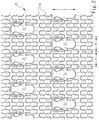
- U.S. patent No. 8,640,503 discloses a knitwear with a perforated structure. As shown in FIG. 1 , its knitwear 10 is knitted by a double jersey knitting machine with machine fineness ⁇ needles/inch 24 and includes a first needle support structure and a second needle support structure opposing each other.
- the first needle support structure includes latch needles at a needle number per inch mating the machine fineness.
- the second needle support structure has transfer needles with a maximum needle number per inch one half of the latch needles of the first needle support structure.
- the transfer needles generate a pore 11 which includes a plurality of loop accumulations each has at least one or preferably two tuck loops 12.
- the tuck loops 12 in the condition of not connecting to or connecting to at least one needle leg, can be transferred from the transfer needle and suspended on the latch needle.
- the structure of the pore 11 formed on the knitwear 10 still has shortcomings, notably: 1.
- the pore 11 is formed in a symmetrical manner on the knitwear 10, namely the pore 11 is supported merely by the tuck loops 12 formed in a loop by a single latch needle on the left side or the right side, and the pore 11 also is formed in a size and shape at a smaller hole width, hence cannot meet market requirements; 2.
- the tuck loops 12 are formed on a single side by the transfer needle via a yarn transferred in the pore 11, hence the length of the pore 11 and the distance between neighboring pores 11 can merely be controlled by the transferred and suspended quantity of the tuck loops 12, and the size and shape of the pore 11 cannot be changed. As a result, it cannot meet emergency requirements in response to change of market.
- GB 404 078 A relates to a circular knitting machine to provide pelerine stitch formations in the knitted fabrics produced thereon.
- GB 404 078 A is mainly concerned with mechanism in or for a circular hose producing machine to provide ornamental pelerine openwork stitches at the sides and/or top portions of the hose leg.
- GB 556 084 A relates to a machine for producing patterned knitted fabric wherein the pattern effect is produced by lap or wrap or embroidery stitch effects and transferred loop stitch effects directly associated.
- WO 2005/092199 A1 relates to a garment which provides a weft knitted fabric having an open fabric effect that is sufficiently stable against run-back to enable the fabric to be used as a garment fabric. Also, the garment provides a weft knitted fabric that is stable against run-back and may be knit from lightweight yarns to produce a fabric having lacelike characteristics, such as visually looking like lace and having a similar weight per unit area as lace.
- WO 2006/136312 A1 relates to a method for knitting manufactured articles with circular knitting machines, particularly high-fineness circular knitting machines, which consists in that at least once during the formation of the manufactured article the number of active needles is reduced by transferring the last loop of knitting formed by certain needles to contiguous needles and thus excluding from knitting the needles that have transferred the loop of knitting during the formation of at least one subsequent row of knitting by the other o needles that are kept active.
- This provides a manufactured article which has regions knitted with a certain number of needles and regions knitted with a smaller number of needles, obtaining particular transparency or shaping effects on the manufacture.
- GB 2 144 158 discloses a circular knitting machine for knitting pelerine stitch knitwear according to the preamble of independent claim 1. As is the case also with circular knitting machines according to GB 404 078 A and GB 556 084 A , the circular knitting machines knit pelerine stitches involving two adjacent needles passing perpendicularly through an opening in a radially reciprocable dial sinker.
- the primary object of the present invention is to solve the shortcomings and problems of the conventional techniques, namely to meet market and consumer requirements for more comfortable cooling, and also provide flexible change of the size of air permeable holes to meet different requirements in the industry and emergency in response to change of the market.
- the present invention provides a circular knitting machine for fine knitwear with air permeable holes.
- the fine knitwear is a single face fabric knitted by a circular knitting machine with knitting fineness ⁇ 24 needles/inch.
- the fine knitwear includes a plurality of air permeable holes that are spaced from each other.
- Each air permeable hole includes; at least one transferred yarn located above the air permeable hole and formed via interactive movements of a Dial sinker (also called Dial-transfer-jack Sinker) and a plurality of latch needles perpendicular to the Dial sinker, and a first support loop and a second support loop that are formed via interactive movements of the Dial sinker and the latch needles and symmetrical against the transferred yarn on the left side and the right side of the transferred yarn to support and tie the transferred yarn.
- a Dial sinker also called Dial-transfer-jack Sinker
- latch needles perpendicular to the Dial sinker
- first support loop and a second support loop that are formed via interactive movements of the Dial sinker and the latch needles and symmetrical against the transferred yarn on the left side and the right side of the transferred yarn to support and tie the transferred yarn.
- the fine knitwear of circular knitting machines with air permeable holes includes a first transferred yarn and a second transferred yarn that are located above each air permeable hole and formed via interactive movements of the Dial sinker and two latch needles, and the first support loop and the second support loop that are formed via interactive movements of the Dial sinker and the two latch needles and symmetrical against the first transferred yarn and the second transferred yarn on the left side and the right side of the first transferred yarn and the second transferred yarn to support and tie the first transferred yarn and the second transferred yarn.
- the fine knitwear of circular knitting machines with air permeable holes includes the first transferred yarn, the second transferred yarn and a third transferred yarn that are located above each air permeable hole and formed via interactive movements of the Dial sinker and the two latch needles, and the first support loop and the second support loop that are formed via interactive movements of the Dial sinker and the two latch needles and symmetrical against the first transferred yarn, the second transferred yarn and the third transferred yarn on the left side and the right side of the first transferred yarn, the second transferred yarn and the third transferred yarn to support and tie the first transferred yarn, the second transferred yarn and the third transferred yarn.
- the fine knitwear of circular knitting machines with air permeable holes includes the first transferred yarn, the second transferred yarn, the third transferred yarn and a fourth transferred yarn that are located above each air permeable hole and formed via interactive movements of the Dial sinker and the two latch needles, and the first support loop and the second support loop that are formed via interactive movements of the Dial sinker and the two latch needles and symmetrical against the first transferred yarn, the second transferred yarn, the third transferred yarn and the fourth transferred yarn on the left side and the right side of the first transferred yarn, the second transferred yarn, the third transferred yarn and the fourth transferred yarn to support and tie the first transferred yarn, the second transferred yarn, the third transferred yarn and the fourth transferred yarn.
- the fine knitwear of circular knitting machines with air permeable holes includes the yarn which is located above each air permeable hole and formed via interactive movements of the Dial sinker and three latch needles, and the first support loop, the second support loop and a third support loop interposed between the first support loop and the second support loop that are formed via interactive movements of the Dial sinker and the three latch needles and symmetrical against the transferred yarn to support and tie the transferred yarn.
- the fine knitwear of circular knitting machines with air permeable holes includes a first transferred yarn and a second transferred yarn that are located above each air permeable hole and formed via interactive movements of the Dial sinker and the three latch needles, and the first support loop, the second support loop and the third support loop that are formed via interactive movements of the Dial sinker and the three latch needles and symmetrical against the first transferred yarn and the second transferred yarn to support and tie the first transferred yarn and the second transferred yarn.
- the fine knitwear of circular knitting machines with air permeable holes includes a spaced loop located in each air permeable hole that is formed by yarn binding of the third support loop.
- the fine knitwear of circular knitting machines with air permeable holes includes the yarn located above each air permeable hole and formed via interactive movements of the Dial sinker and four latch needles, and the first support loop, the second support loop and a third support loop and a fourth support loop interposed between the first support loop and the second support loop are formed via interactive movements of the Dial sinker and the four latch needles and symmetrical against the yarn on the left side and the right side of the transferred yarn to support and tie the transferred yarn.
- the fine knitwear of circular knitting machines with air permeable holes includes a first transferred yarn and a second transferred yarn that are located above each air permeable hole and formed via interactive movements of the Dial sinker and the four latch needles, and the first support loop, the second support loop, the third support loop and the fourth support loop that are formed via interactive movements of the Dial sinker and the fourth latch needles and symmetrical against the first transferred yarn and the second transferred yarn to support and tie the first transferred yarn and the second transferred yarn.
- each air permeable hole of the fine knitwear of circular knitting machines with air permeable holes includes two spaced loops formed at the same time by yarn binding of the third support loop and the fourth support loop.
- the present invention by means of the technique set forth above, compared with the conventional techniques, can provide many advantages, notably: 1.
- the invention forms the air permeable hole symmetrically on the left side and the right side, hence the hole can be formed wider and at a greater distance, and the transferred yarn above the air permeable hole is securely held by at least two support loops, thus the air permeable hole can be constructed firmer to meet market requirements; 2.
- the transferred yarns above the air permeable hole are stacked over one another in a symmetrical manner on the left side and the right side, the stacked yarns form a three-dimension (3D in short hereinafter) jutting profile, thereby when the fine knitwear is in contact with people's skin each air permeable hole and the skin form a plurality of gaps between them without directly sticking to the skin, thus can generate improved air permeable effect and provide more comfortable cooling to meet consumers' requirements; 3.
- 3D in short hereinafter three-dimension
- the distance between neighboring air permeable holes also can be controlled by the positions of the transferred yarns; and by adjusting the shape of the Dial sinker the width or shape of the air permeable holes also can be controlled, thereby can meet emergency requirements in response to change of market.
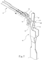
- the circular knitting machine 40 includes a plurality of Dial sinkers 60 and latch needles 50 at a quantity double the number of the Dial sinkers 60 and perpendicular to the Dial sinkers 60 with knitting fineness ⁇ 24 needles/inch.
- the knitting fineness of the circular knitting machine according to the invention is preferably 28 needles/inch.
- the number of the latch needles 50 is an integer multiple of 2 or more of the number of the Dial sinkers 60, preferably 2-4 times, with optimal number at twofold of the Dial sinkers 60 as already known from the prior art.
- the fine knitwear 20 is a single face fabric with a plurality of air permeable holes 21 spaced from one another.
- the hole 21 is formed in a symmetrical manner on the left side and the right side, the hole can be formed at a greater width W. Moreover, since the first transferred yarn 301 and the second transferred yarn 302 above the air permeable hole 21 are securely held by at least two support loops (the first support loop 311 and the second support loop 312), the structure of the air permeable hole 21 also is firmer, thus can meet market requirements.
- first transferred yarn 301 and the second transferred yarn 302 above the air permeable hole 21 are stacked symmetrically on the left side and the right side, a jutting 3D profile can be formed above the air permeable hole 21, therefore when the fine knitwear 20 is in contact with people's skin a plurality of gaps are formed between each air permeable hole 21 and the skin without directly sticking to the skin. As a result, an improved air permeable effect can be generated to meet consumers' requirement for more comfortable cooling.
- the Dial sinkers 60 used in the invention not only can control the length L of the hole and the distance D between the neighboring air permeable holes 21, the shape of the Dial sinkers 60 also can be adjusted to control the width W or shape of the air permeable holes 21, thus can meet emergency requirements in response to change of market.
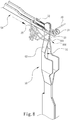
- FIGS. 6 through 14 illustrate continuous operation conditions of knitting process according to FIG. 5 with the Dial sinker shaped in a known form and the latch needles transferring the yarn twice
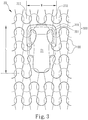
- FIG. 3 illustrates a knitting process with the yarn transferred twice.
- two latch needles 50 are provided each has a hook 51 at a front end and a latch 52 to close the hook 51.
- the Dial sinker 60 has an opening 61 at an upper side to allow the two latch needles 50 to pass through in a perpendicular manner at the same time, a guide portion 62 extended from the upper side of the opening 61 at two sides thereof, and an extended portion 63 extended from the upper side of the guide portion 62.
- knitting operation can be started according to a preset knitting process (such as knitting with the yarn transferred twice, as shown in FIG. 14 ).
- a preset knitting process such as knitting with the yarn transferred twice, as shown in FIG. 14 .
- the two latch needles 50 catch a yarn 30 to form two loops that are coupled together, namely, when the two latch needles 50 catch the yarn 30 to form the loops in normal conditions the Dial sinker 60 is lowered to the lowest position without generating interactive movements with the two latch needles 50; next, the two latch needles 50 perform knitting operation according to another knitting process 3, and the Dial sinker 60 is moved slightly upward to form interactive movements with the two latch needles 50 as show in FIG.
- the two latch needles 50 catch in different time sequence the yarn 30 fed subsequently to form a first transferred yarn 301 on the extended portion 63 as shown in FIG. 7 ; similarly, the two latch needles 50 perform knitting operation according to a further knitting process 4, thereafter the Dial sinker 60 forms interactive movements with the two latch needles 50 as show in FIG. 8 , and the two latch needles 50 catch the yarn 30 fed next to form a second transferred yarn 302 on the extended portion 63 as shown in FIG.
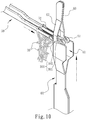
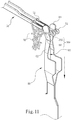
- the knitting operation can proceed according to yet another knitting process 5, and the Dial sinker 60 is moved upward again until the two latch needles 50 extend into the opening 61; at that moment the Dial sinker 60 moves upward rapidly to make the first transferred yarn 301 and the second transferred yarn 302 to drop at the same time inside the hook 51 at the front end of the two latch needles 50 as shown in FIG. 10 ; then the Dial sinker 60 drops quickly to the lowest position to allow the first transferred yarn 301 and the second transferred yarn 302 to be moved away from the Dial sinker 60 by the two latch needles 50 at the same time as shown in FIG. 11 ; meanwhile, the two latch needles 50 are fully extended again to catch the yarn 30 fed next time as shown in FIG.
- first support loop 311 and a second support loop 312 that are symmetrical against the first transferred yarn 301 and the second transferred yarn 302 on the left side and the right side of the first transferred yarn 301 and the second transferred yarn 302 to support and tie the first transferred yarn 301 and the second transferred yarn 302, and an air permeable hole 21 also is formed as shown in FIG. 12 ; finally, in order to separate one air permeable hole 21 and another air permeable hole 21 another kitting process 6 can be performed so that the two latch needles 50 can catch the yarn 30 fed subsequently to form loops as in the normal conditions.
- FIGS. 15 and 16 for a second process and fabric.
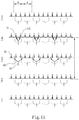
- the second process is implemented by omitting the knitting process 4 in the first process version previously discussed as shown in FIG. 14 , and the resulting knitting process is shown in FIG. 15 ; namely, after the circular knitting machine 40 (as shown in FIG.
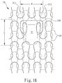
- the knitting process 5 is activated it performs the knitting operation in the knitting processes 1 and 2 with the yarn 30 transferred once, and the yarn 30 is caught to form two coupled loops in the normal conditions; next, the knitting process 3 is carried out to form a transferred yarn 300; after the knitting process 4 is performed a first support loop 311 and a second support loop 312 are formed that are symmetrical against the transferred yarn 300 on the left side and the right side to support and tie the transferred yarn 300, and an air permeable hole 21 also is formed as shown in FIG. 16 ; finally, the air permeable hole 21 and another air permeable hole 21 are separated and spaced from each other, and the knitting process 5 is performed to finish knitting of the loop.
- the width W of the hole in the second fabric is same as that in the first fabric, but the length L of the hole in the second fabric is smaller than that in the first fabric.
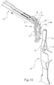
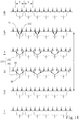
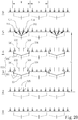
- FIGS. 17 and 18 illustrate the knitting processes with the yarn transferred three times and four times. Compared FIGS. 17 and 18 with FIG. 14 , after the knitting process 4 shown in FIG. 14 , another knitting process 5 is added in FIG. 17 to form a third transferred yarn 303, or additional knitting process 5 to form the third transferred yarn 303 and knitting process 6 to form a fourth transferred yarn are added in FIG. 18 . It is to be noted that the width W of the hole in FIGS. 17 and 18 is same as that in FIG. 14 , but the length L of the hole in FIGS. 17 and 18 is greater than that in FIG. 14 , and the length L of the hole in FIG, 18 also is greater than that in FIG. 17 .
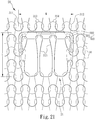
- FIGS. 19 through 21 for a first embodiment with the Dial sinker shaped in a novel form and positioned relative to the latch needles, and a first knitting process with the yarn transferred twice.
- four latch needles 50 (a first latch needle 501, a second latch needle 502, a third latch needle 503 and a fourth latch needle 504) are provided each has a hook 51 at the front end and a latch 52 to close the hook 51
- the Dial sinker 60 has an opening 61 at the upper side to allow the first latch needle 501, the second latch needle 502, the third latch needle 503 and the fourth latch needle 504 to pass through perpendicularly at the same time, a guide portion 62 extended from the upper side of the opening 61 at two sides and an extended portion 63 extended from the upper side of the guide portion 62.
- the circular knitting machine 40 (as shown in FIG. 5 ) is activated knitting operation according to a preset knitting process (as shown in FIG. 20 for a knitting process of transferring the yarn twice) can be performed.
- the four latch needles 50 (including the first latch needle 501, the second latch needle 502, the third latch needle 503 and the fourth latch needle 504) catch the yarn 30 fed in the normal conditions to form respectively two loops that are coupled with each other; namely, when the four latch needles 50 catch the yarn 30 to form the loops in the normal conditions the Dial sinker 60 is lowered to the lowest position without generating interactive movement with the latch needles 50; next, knitting operation is performed according to the knitting process 3 with the first latch needle 501 and the fourth latch needle 504 fully extended, and the second latch needle 502 and the third latch needle 503 extended one half, and the Dial sinker 60 rises slightly to form interactive movements with the first latch needle 501 and the fourth latch needle 504, then the first latch needle 501 and the fourth latch needle 504 knit
- the second latch needle 502 and the third latch needle 503 also can form respectively a third support loop 313 and a fourth support loop 314 between the first support loop 311 and the second support loop 312; and the air permeable hole 21 also has two spaced loops 315 formed by yarn binding of the third support loop 313 and the fourth support loop 314 at the same time.
- the knitting process 6 is performed to allow the first latch needle 501, the second latch needle 502, the third latch needle 503 and the fourth latch needle 504 to catch the yarn 30 fed next to form the loops in the normal conditions as shown in FIG. 21 .
- the width W of the hole formed in the third fabric is greater than that of the first fabric and the length L of the hole in the third fabric is the same as that of the first fabric Similarly, when the yarn transferring quantity is changed, the L of the hole also is changed accordingly no matter how many latch needles 50 passing through the opening 61 of the Dial sinker 60 at the same time.
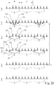
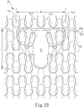
- FIGS. 22 and 23 for a fourth process and fabric made with the Dial sinker shaped in the first novel form and a second knitting process with the yarn transferred twice.
- the circular knitting machine 40 is activated (as shown in FIG. 5 ) knitting operation according to a present knitting process (such as the knitting process with yarn transferred twice shown in FIG. 22 ) is performed.
- the four latch needles 50 (including a first latch needle 501, a second latch needle 502, a third latch needle 503 and a fourth latch needle 504) catch the yarn 30 in normal conditions to form two loops which are coupled with each other; namely, when the four latch needles 50 catch the yarn 30 to form the loops in the normal conditions the Dial sinker 60 is lowered to the lowest position without generating interactive movement with the fourth latch needles 504; next, knitting operation is performed according to the knitting process 3 with the first latch needle 501, the second latch needle 502, the third latch needle 503 and the fourth latch needle 504 fully extended, and the Dial sinker 60 rises slightly to form interactive movements with the second latch needle 502 and the third latch needle 503, then the first latch needle 501, the second latch needle 502, the third latch needle 503 and the fourth latch needle 504 catch respectively in different time sequence the yarn 30 fed next time, and the second latch needle 502 and the third latch needle 503 form on the extended portion 63 the first transferred yarn 301; similarly,
- the second latch needle 502 and the third latch needle 503 also can form respectively a third support loop 313 and a fourth support loop 314 between the first support loop 311 and the second support loop 312;
- knitting operation of the knitting process 6 can be performed to allow the first latch needle 501, the second latch needle 502, the third latch needle 503 and the fourth latch needle 504 to catch the yarn 30 fed next to form the loops in the normal conditions as shown in FIG. 23 .
- the width W of the hole formed in the fourth fabric is greater than that of the first fabric; similarly, due to the fourth process which transfers the yarn twice, the length L of the hole in the fourth fabric is greater than that of the first fabric.
- FIGS. 24 , 25 and 26 for a fifth process and fabric made with the Dial sinker shaped in a second novel form and positioned relative to the latch needles, and a knitting process with the yarn transferred twice. First, as shown in FIG.
- three latch needles 50 (including a first latch needle 501, a second latch needle 502 and a third latch needle 503) are provided each has a hook 51 at the front end and a latch 52 to close the hook 51, and the Dial sinker 60 includes an opening 61 to allow the first latch needle 501, the second latch needle 502 and the third latch needle 503 to pass through perpendicularly, a guide portion 62 extended from the upper side of the opening 61 at two sides and an extended portion 63 extended from the upper side of the guide portion 62.
- the circular knitting machine 40 is activated (as shown in FIG. 5 ) knitting operation according to a present knitting process (such as the knitting process with yarn transferred twice shown in FIG. 25 ) can be performed.
- the three latch needles 50 (including the first latch needle 501, the second latch needle 502 and the third latch needle 503) catch the yarn 30 in normal conditions to form two loops which are coupled with each other; namely, when the three latch needles 50 catch the yarn 30 to form the loops in the normal conditions the Dial sinker 60 is lowered to the lowest position without generating interactive movements with the three latch needles 50; next, knitting operation is performed according to the knitting process 3 with the first latch needle 501 and the third latch needle 503 fully extended, while the second latch needle 502 is extended one half, and the Dial sinker 60 rises slightly to form interactive movements with the first latch needle 501 and the third latch needle 503, then the first latch needle 501 and the third latch needle 503 catch the yarn 30 fed next time to form the first transferred yarn 301 on the extended portion 63; similarly, when knitting operation of the knitting process 4 is performed the Dial sinker 60 forms interactive movements with the first latch needle 501 and the third latch needle 503 that also catch the yarn 30 fed next time to form
- the second latch needle 502 also can form a third support loop 313 between the first support loop 311 and the second support loop 312, and the air permeable hole 21 also has a spaced loop 315 inside formed by yarn binding of the third support loop 313; finally, in order to separate the air permeable hole 21 from another air permeable hole 21 knitting operation of the knitting process 6 can be performed to allow the first latch needle 501, the second latch needle 502 and the third latch needle 503 to catch the yarn 30 fed next to form the loops in the normal conditions as shown in FIG. 26 .
- the width W of the hole formed in the fifth fabric is greater than that of the first fabric; similarly, due to the fifth process which transfers the yarn 30 twice, the length L of the hole in the fifth fabric is greater than that of the first fabric.
- the air permeable hole 21 is formed in a symmetrical fashion on the left side and the right side, hence the width W of the hole can be formed greater.
- the first transferred yarn 301 and the second transferred yarn 302 above the air permeable hole 21 are securely held by at least two support loops (the first support loop 311 and the second support loop 312), hence the structure of the air permeable hole 21 is firmer and can meet market requirements.
- the first transferred yarn 301 and the second transferred yarn 302 above the air permeable hole 21 stack over each other symmetrically on the left side and the right side, therefore a jutting 3D profile is formed above the air permeable hole 21.
- the fine knitwear 20 when the fine knitwear 20 is in contact with people's skin a plurality of gaps are formed between each air permeable hole 21 and the skin to improve air permeability. As a result, it can provide more comfortable cooling effect to meet consumers' requirements. Furthermore, through the Dial sinker 60 used in the invention the length L of the air permeable hole 21 and the distance D between neighboring air permeable holes 21 can be controlled, and by adjusting the shape of the Dial sinker 60 the width W or the shape of the air permeable hole 21 also can be controlled, therefore can meet emergency requirements in response to change of market.
Description
- The present invention relates to circular knitting machines that are able to knit fine knitwear with air permeable holes and have a fineness ≧ 24 needles/inch.
- Nowadays people are very conscious of health, environmental protection and fashions. Consumers also have growing demand on comfort and design of their clothing fabrics, The comfort sense of clothing fabrics can be improved through air permeability or their stitching methods. On the issue of air permeability the conventional approach is knitting fabrics with a mesh structure via a warp knitting machine to form mesh knitwear with greater hole width to achieve desired air permeable effect. But such an approach cannot knit fine knitwear with fineness ≧ 24 needles/inch. The knitting speed also is quite slow. The deficiency in fineness and productivity become a constraint that cannot fully meet textile industry requirement.
-
U.S. patent No. 8,640,503 discloses a knitwear with a perforated structure. As shown inFIG. 1 , itsknitwear 10 is knitted by a double jersey knitting machine with machine fineness ≧ needles/inch 24 and includes a first needle support structure and a second needle support structure opposing each other. The first needle support structure includes latch needles at a needle number per inch mating the machine fineness. The second needle support structure has transfer needles with a maximum needle number per inch one half of the latch needles of the first needle support structure. The transfer needles generate apore 11 which includes a plurality of loop accumulations each has at least one or preferably twotuck loops 12. Thetuck loops 12, in the condition of not connecting to or connecting to at least one needle leg, can be transferred from the transfer needle and suspended on the latch needle. - Based on the aforesaid technique, as shown in
FIG. 1 , the structure of thepore 11 formed on theknitwear 10 still has shortcomings, notably: 1. Thepore 11 is formed in a symmetrical manner on theknitwear 10, namely thepore 11 is supported merely by thetuck loops 12 formed in a loop by a single latch needle on the left side or the right side, and thepore 11 also is formed in a size and shape at a smaller hole width, hence cannot meet market requirements; 2. Thetuck loops 12 are formed on a single side by the transfer needle via a yarn transferred in thepore 11, hence the length of thepore 11 and the distance between neighboringpores 11 can merely be controlled by the transferred and suspended quantity of thetuck loops 12, and the size and shape of thepore 11 cannot be changed. As a result, it cannot meet emergency requirements in response to change of market. -
GB 404 078 A GB 404 078 A -
GB 556 084 A -
WO 2005/092199 A1 relates to a garment which provides a weft knitted fabric having an open fabric effect that is sufficiently stable against run-back to enable the fabric to be used as a garment fabric. Also, the garment provides a weft knitted fabric that is stable against run-back and may be knit from lightweight yarns to produce a fabric having lacelike characteristics, such as visually looking like lace and having a similar weight per unit area as lace. -
WO 2006/136312 A1 relates to a method for knitting manufactured articles with circular knitting machines, particularly high-fineness circular knitting machines, which consists in that at least once during the formation of the manufactured article the number of active needles is reduced by transferring the last loop of knitting formed by certain needles to contiguous needles and thus excluding from knitting the needles that have transferred the loop of knitting during the formation of at least one subsequent row of knitting by the other o needles that are kept active. This provides a manufactured article which has regions knitted with a certain number of needles and regions knitted with a smaller number of needles, obtaining particular transparency or shaping effects on the manufacture. -
GB 2 144 158independent claim 1. As is the case also with circular knitting machines according toGB 404 078 A GB 556 084 A - The primary object of the present invention is to solve the shortcomings and problems of the conventional techniques, namely to meet market and consumer requirements for more comfortable cooling, and also provide flexible change of the size of air permeable holes to meet different requirements in the industry and emergency in response to change of the market.
- To achieve the foregoing object the present invention provides a circular knitting machine for fine knitwear with air permeable holes. The fine knitwear is a single face fabric knitted by a circular knitting machine with knitting fineness ≧ 24 needles/inch. The fine knitwear includes a plurality of air permeable holes that are spaced from each other. Each air permeable hole includes; at least one transferred yarn located above the air permeable hole and formed via interactive movements of a Dial sinker (also called Dial-transfer-jack Sinker) and a plurality of latch needles perpendicular to the Dial sinker, and a first support loop and a second support loop that are formed via interactive movements of the Dial sinker and the latch needles and symmetrical against the transferred yarn on the left side and the right side of the transferred yarn to support and tie the transferred yarn.
- In one aspect the fine knitwear of circular knitting machines with air permeable holes includes a first transferred yarn and a second transferred yarn that are located above each air permeable hole and formed via interactive movements of the Dial sinker and two latch needles, and the first support loop and the second support loop that are formed via interactive movements of the Dial sinker and the two latch needles and symmetrical against the first transferred yarn and the second transferred yarn on the left side and the right side of the first transferred yarn and the second transferred yarn to support and tie the first transferred yarn and the second transferred yarn.
- In another aspect the fine knitwear of circular knitting machines with air permeable holes includes the first transferred yarn, the second transferred yarn and a third transferred yarn that are located above each air permeable hole and formed via interactive movements of the Dial sinker and the two latch needles, and the first support loop and the second support loop that are formed via interactive movements of the Dial sinker and the two latch needles and symmetrical against the first transferred yarn, the second transferred yarn and the third transferred yarn on the left side and the right side of the first transferred yarn, the second transferred yarn and the third transferred yarn to support and tie the first transferred yarn, the second transferred yarn and the third transferred yarn.
- In yet another aspect the fine knitwear of circular knitting machines with air permeable holes includes the first transferred yarn, the second transferred yarn, the third transferred yarn and a fourth transferred yarn that are located above each air permeable hole and formed via interactive movements of the Dial sinker and the two latch needles, and the first support loop and the second support loop that are formed via interactive movements of the Dial sinker and the two latch needles and symmetrical against the first transferred yarn, the second transferred yarn, the third transferred yarn and the fourth transferred yarn on the left side and the right side of the first transferred yarn, the second transferred yarn, the third transferred yarn and the fourth transferred yarn to support and tie the first transferred yarn, the second transferred yarn, the third transferred yarn and the fourth transferred yarn.
- In yet another aspect the fine knitwear of circular knitting machines with air permeable holes includes the yarn which is located above each air permeable hole and formed via interactive movements of the Dial sinker and three latch needles, and the first support loop, the second support loop and a third support loop interposed between the first support loop and the second support loop that are formed via interactive movements of the Dial sinker and the three latch needles and symmetrical against the transferred yarn to support and tie the transferred yarn.
- In yet another aspect the fine knitwear of circular knitting machines with air permeable holes includes a first transferred yarn and a second transferred yarn that are located above each air permeable hole and formed via interactive movements of the Dial sinker and the three latch needles, and the first support loop, the second support loop and the third support loop that are formed via interactive movements of the Dial sinker and the three latch needles and symmetrical against the first transferred yarn and the second transferred yarn to support and tie the first transferred yarn and the second transferred yarn.
- In yet another aspect the fine knitwear of circular knitting machines with air permeable holes includes a spaced loop located in each air permeable hole that is formed by yarn binding of the third support loop.
- In yet another aspect the fine knitwear of circular knitting machines with air permeable holes includes the yarn located above each air permeable hole and formed via interactive movements of the Dial sinker and four latch needles, and the first support loop, the second support loop and a third support loop and a fourth support loop interposed between the first support loop and the second support loop are formed via interactive movements of the Dial sinker and the four latch needles and symmetrical against the yarn on the left side and the right side of the transferred yarn to support and tie the transferred yarn.
- In yet another aspect the fine knitwear of circular knitting machines with air permeable holes includes a first transferred yarn and a second transferred yarn that are located above each air permeable hole and formed via interactive movements of the Dial sinker and the four latch needles, and the first support loop, the second support loop, the third support loop and the fourth support loop that are formed via interactive movements of the Dial sinker and the fourth latch needles and symmetrical against the first transferred yarn and the second transferred yarn to support and tie the first transferred yarn and the second transferred yarn.
- In yet another aspect each air permeable hole of the fine knitwear of circular knitting machines with air permeable holes includes two spaced loops formed at the same time by yarn binding of the third support loop and the fourth support loop.
- The present invention, by means of the technique set forth above, compared with the conventional techniques, can provide many advantages, notably: 1. The invention forms the air permeable hole symmetrically on the left side and the right side, hence the hole can be formed wider and at a greater distance, and the transferred yarn above the air permeable hole is securely held by at least two support loops, thus the air permeable hole can be constructed firmer to meet market requirements; 2. Because the transferred yarns above the air permeable hole are stacked over one another in a symmetrical manner on the left side and the right side, the stacked yarns form a three-dimension (3D in short hereinafter) jutting profile, thereby when the fine knitwear is in contact with people's skin each air permeable hole and the skin form a plurality of gaps between them without directly sticking to the skin, thus can generate improved air permeable effect and provide more comfortable cooling to meet consumers' requirements; 3. Through the Dial sinker not only the length of the air permeable holes can be determined by the number of the transferred yarns, the distance between neighboring air permeable holes also can be controlled by the positions of the transferred yarns; and by adjusting the shape of the Dial sinker the width or shape of the air permeable holes also can be controlled, thereby can meet emergency requirements in response to change of market.
- The foregoing, as well as additional objects, features and advantages of the invention will be more readily apparent from the following detailed description, which proceeds with reference to the accompanying drawings.
-
-
FIG. 1 is a fragmentary enlarged plane view of a conventional knitwear. -
FIG. 2 is a fragmentary schematic view of a first example of pelerine stitches known in the prior art and formed by transferring the yarn twice, -
FIG. 3 is a fragmentary enlarged view according toFIG. 2 . -
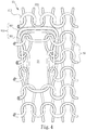
FIG. 4 is a fragmentary perspective view according toFIG. 3 . -
FIG. 5 is a fragmentary schematic view of a circular knitting machine used in the invention. -
FIGS. 6 through 13 are fragmentary enlarged views of the Dial sinker in a first form inFIG. 5 and schematic views of the Dial sinker and latch needles in continuous knitting operation conditions by transferring the yarn twice. -
FIG. 14 is a schematic view of the knitting process according toFIG. 3 by transferring the yarn twice. -
FIG. 15 is a schematic view of the knitting process by transferring the yarn once. -
FIG. 16 is a fragmentary enlarged view of a variation of the fabric obtained by the process - according to
FIG. 15 . -
FIG. 17 is a schematic view of the knitting process by transferring the yarn three times. -
FIG. 18 is a schematic view of the knitting process by transferring the yarn four times. -
FIG. 19 is a fragmentary enlarged view of relative positioning of the Dial sinker in a first embodiment of the invention and the latch needles according toFIG. 5 . -
FIG. 20 is a schematic view of a first knitting process of the invention by transferring the yarn twice through the Dial sinker in the form shown inFIG. 19 . -
FIG. 21 is a fragmentary enlarged view of a fabric obtained by the process according toFIG. 20 . -
FIG. 22 is a schematic view of a second knitting process of the invention by transferring the yarn twice through the Dial sinker in the form shown inFIG. 19 . -
FIG. 23 is a fragmentary enlarged view of a another fabric obtainable by the process according toFIG. 22 . -
FIG. 24 is a fragmentary enlarged view of relative positioning of the Dial sinker in a second embodiment of the invention and the latch needles according toFIG. 5 . -
FIG. 25 is a schematic view of the knitting process by transferring the yarn twice through the Dial sinker in the form shown inFIG. 24 . -
FIG. 26 is a fragmentary enlarged view of a another fabric obtainable by the process according toFIG. 25 . - Refer to
FIGS. 2 through 5 for a first understanding of the invention. It is implemented through acircular knitting machine 40 by transferring the yarn twice to produce a circular fine knitwear (rundstrickware) with air permeable holes (the main structure of thecircular knitting machine 40 is known in the art, thus details are omitted in the drawings herein). Thecircular knitting machine 40 includes a plurality ofDial sinkers 60 and latch needles 50 at a quantity double the number of theDial sinkers 60 and perpendicular to theDial sinkers 60 with knitting fineness ≧ 24 needles/inch. The knitting fineness of the circular knitting machine according to the invention is preferably 28 needles/inch. - The number of the latch needles 50 is an integer multiple of 2 or more of the number of the
Dial sinkers 60, preferably 2-4 times, with optimal number at twofold of theDial sinkers 60 as already known from the prior art. Through the circular knitting machine 40 afine knitwear 20 can be produced by knitting. Thefine knitwear 20 is a single face fabric with a plurality of airpermeable holes 21 spaced from one another. It is to be noted that there are transferredyarns 300 above each airpermeable hole 21 that are formed via interactive movements of theDial sinkers 60 and two sets of the latch needles 50 perpendicular and corresponding to the Dial sinkers 60 (a first example of a first transferredyarn 301 and a second transferredyarn 302 formed via the interactive movements twice is shown in the drawings for discussion), and afirst support loop 311 and asecond support loop 312 that are formed via interactive movement of theDial sinkers 60 and the two latch needles 50 and symmetrical against the first transferredyarn 301 and the second transferredyarn 302 on the left side and the right side of the first transferredyarn 301 and the second transferredyarn 302 to support and tie the first transferredyarn 301 and the second transferredyarn 302. It is also to be noted that, since the airpermeable hole 21 is formed in a symmetrical manner on the left side and the right side, the hole can be formed at a greater width W. Moreover, since the first transferredyarn 301 and the second transferredyarn 302 above the airpermeable hole 21 are securely held by at least two support loops (thefirst support loop 311 and the second support loop 312), the structure of the airpermeable hole 21 also is firmer, thus can meet market requirements. In addition, because the first transferredyarn 301 and the second transferredyarn 302 above the airpermeable hole 21 are stacked symmetrically on the left side and the right side, a jutting 3D profile can be formed above the airpermeable hole 21, therefore when thefine knitwear 20 is in contact with people's skin a plurality of gaps are formed between each airpermeable hole 21 and the skin without directly sticking to the skin. As a result, an improved air permeable effect can be generated to meet consumers' requirement for more comfortable cooling. Furthermore, theDial sinkers 60 used in the invention not only can control the length L of the hole and the distance D between the neighboring airpermeable holes 21, the shape of theDial sinkers 60 also can be adjusted to control the width W or shape of the airpermeable holes 21, thus can meet emergency requirements in response to change of market. - To facilitate discussion of a first process and fabric of the
fine knitwear 20,FIGS. 6 through 14 illustrate continuous operation conditions of knitting process according toFIG. 5 with the Dial sinker shaped in a known form and the latch needles transferring the yarn twice, andFIG. 3 illustrates a knitting process with the yarn transferred twice. First, as shown inFIG. 6 , two latch needles 50 are provided each has ahook 51 at a front end and alatch 52 to close thehook 51. TheDial sinker 60 has anopening 61 at an upper side to allow the two latch needles 50 to pass through in a perpendicular manner at the same time, aguide portion 62 extended from the upper side of theopening 61 at two sides thereof, and anextended portion 63 extended from the upper side of theguide portion 62. When thecircular knitting machine 40 is activated (referring toFIG. 5 ) knitting operation can be started according to a preset knitting process (such as knitting with the yarn transferred twice, as shown inFIG. 14 ). During knitting process 1 and knitting process 2 the two latch needles 50 catch a yarn 30 to form two loops that are coupled together, namely, when the two latch needles 50 catch the yarn 30 to form the loops in normal conditions the Dial sinker 60 is lowered to the lowest position without generating interactive movements with the two latch needles 50; next, the two latch needles 50 perform knitting operation according to another knitting process 3, and the Dial sinker 60 is moved slightly upward to form interactive movements with the two latch needles 50 as show inFIG. 6 ; next, the two latch needles 50 catch in different time sequence the yarn 30 fed subsequently to form a first transferred yarn 301 on the extended portion 63 as shown inFIG. 7 ; similarly, the two latch needles 50 perform knitting operation according to a further knitting process 4, thereafter the Dial sinker 60 forms interactive movements with the two latch needles 50 as show inFIG. 8 , and the two latch needles 50 catch the yarn 30 fed next to form a second transferred yarn 302 on the extended portion 63 as shown inFIG. 9 ; then the knitting operation can proceed according to yet another knitting process 5, and the Dial sinker 60 is moved upward again until the two latch needles 50 extend into the opening 61; at that moment the Dial sinker 60 moves upward rapidly to make the first transferred yarn 301 and the second transferred yarn 302 to drop at the same time inside the hook 51 at the front end of the two latch needles 50 as shown inFIG. 10 ; then the Dial sinker 60 drops quickly to the lowest position to allow the first transferred yarn 301 and the second transferred yarn 302 to be moved away from the Dial sinker 60 by the two latch needles 50 at the same time as shown inFIG. 11 ; meanwhile, the two latch needles 50 are fully extended again to catch the yarn 30 fed next time as shown inFIG. 12 , and also form a first support loop 311 and a second support loop 312 that are symmetrical against the first transferred yarn 301 and the second transferred yarn 302 on the left side and the right side of the first transferred yarn 301 and the second transferred yarn 302 to support and tie the first transferred yarn 301 and the second transferred yarn 302, and an air permeable hole 21 also is formed as shown inFIG. 12 ; finally, in order to separate one air permeable hole 21 and another air permeable hole 21 another kitting process 6 can be performed so that the two latch needles 50 can catch the yarn 30 fed subsequently to form loops as in the normal conditions. - Refer to
FIGS. 15 and16 for a second process and fabric. The second process is implemented by omitting theknitting process 4 in the first process version previously discussed as shown inFIG. 14 , and the resulting knitting process is shown inFIG. 15 ; namely, after the circular knitting machine 40 (as shown inFIG. 5 ) is activated it performs the knitting operation in the knitting processes 1 and 2 with theyarn 30 transferred once, and theyarn 30 is caught to form two coupled loops in the normal conditions; next, theknitting process 3 is carried out to form a transferredyarn 300; after theknitting process 4 is performed afirst support loop 311 and asecond support loop 312 are formed that are symmetrical against the transferredyarn 300 on the left side and the right side to support and tie the transferredyarn 300, and an airpermeable hole 21 also is formed as shown inFIG. 16 ; finally, the airpermeable hole 21 and another airpermeable hole 21 are separated and spaced from each other, and theknitting process 5 is performed to finish knitting of the loop. It is to be noted that the width W of the hole in the second fabric is same as that in the first fabric, but the length L of the hole in the second fabric is smaller than that in the first fabric. -
FIGS. 17 and18 illustrate the knitting processes with the yarn transferred three times and four times. ComparedFIGS. 17 and18 withFIG. 14 , after theknitting process 4 shown inFIG. 14 , anotherknitting process 5 is added inFIG. 17 to form a third transferredyarn 303, oradditional knitting process 5 to form the third transferredyarn 303 andknitting process 6 to form a fourth transferred yarn are added inFIG. 18 . It is to be noted that the width W of the hole inFIGS. 17 and18 is same as that inFIG. 14 , but the length L of the hole inFIGS. 17 and18 is greater than that inFIG. 14 , and the length L of the hole inFIG, 18 also is greater than that inFIG. 17 . - Refer to
FIGS. 19 through 21 for a first embodiment with the Dial sinker shaped in a novel form and positioned relative to the latch needles, and a first knitting process with the yarn transferred twice. First, as shown inFIG. 19 , four latch needles 50 (afirst latch needle 501, asecond latch needle 502, athird latch needle 503 and a fourth latch needle 504) are provided each has ahook 51 at the front end and alatch 52 to close thehook 51, and theDial sinker 60 has anopening 61 at the upper side to allow thefirst latch needle 501, thesecond latch needle 502, thethird latch needle 503 and thefourth latch needle 504 to pass through perpendicularly at the same time, aguide portion 62 extended from the upper side of theopening 61 at two sides and anextended portion 63 extended from the upper side of theguide portion 62. When the circular knitting machine 40 (as shown inFIG. 5 ) is activated knitting operation according to a preset knitting process (as shown inFIG. 20 for a knitting process of transferring the yarn twice) can be performed. During the knitting processes 1 and 2, the four latch needles 50 (including the first latch needle 501, the second latch needle 502, the third latch needle 503 and the fourth latch needle 504) catch the yarn 30 fed in the normal conditions to form respectively two loops that are coupled with each other; namely, when the four latch needles 50 catch the yarn 30 to form the loops in the normal conditions the Dial sinker 60 is lowered to the lowest position without generating interactive movement with the latch needles 50; next, knitting operation is performed according to the knitting process 3 with the first latch needle 501 and the fourth latch needle 504 fully extended, and the second latch needle 502 and the third latch needle 503 extended one half, and the Dial sinker 60 rises slightly to form interactive movements with the first latch needle 501 and the fourth latch needle 504, then the first latch needle 501 and the fourth latch needle 504 knit respectively in different time sequence the yarn 30 fed next time on the extended portion 63 to form the first transferred yarn 301; similarly, after the knitting process 4 is performed the Dial sinker 60 and the first latch needle 501 and the fourth latch needle 504 form interactive movements with each other to form the second transferred yarn 302 on the extended portion 63 again through the yarn 30 fed the next time; after the knitting operation of the knitting process 5 is finished the Dial sinker 60 rises until the first latch needle 501, the second latch needle 502, the third latch needle 503 and the fourth latch needle 504 pass through the opening 61, then the Dial sinker 60 rises rapidly such that the first transferred yarn 301 and the second transferred yarn 302 drop at the same time to the hooks 51 at the front ends of the first latch needle 501, the second latch needle 502, the third latch needle 503 and the fourth latch needle 504; next, the Dial sinker 60 lowers rapidly to the lowest position such that the first transferred yarn 301 and the second transferred yarn 302 are moved away from the Dial sinker 60 at the same time by the first latch needle 501, the second latch needle 502, the third latch needle 503 and the fourth latch needle 504, meanwhile the first latch needle 501, the second latch needle 502, the third latch needle 503 and the fourth latch needle 504 are fully extended to catch the yarn 30 fed next time, and the first latch needle 501 and the second latch needle 502 form respectively a first support loop 311 and a second support loop 312 that are symmetrical against the first transferred yarn 301 and the second transferred yarn 302 on the left side and the right side of the first transferred yarn 301 and the second transferred yarn 302 to support and tie the first transferred yarn 301 and the second transferred yarn 302, and an air permeable hole 21 also is formed. It is to be noted that thesecond latch needle 502 and thethird latch needle 503 also can form respectively athird support loop 313 and afourth support loop 314 between thefirst support loop 311 and thesecond support loop 312; and the airpermeable hole 21 also has two spacedloops 315 formed by yarn binding of thethird support loop 313 and thefourth support loop 314 at the same time. Finally, in order to separate the airpermeable hole 21 and another airpermeable hole 21 theknitting process 6 is performed to allow thefirst latch needle 501, thesecond latch needle 502, thethird latch needle 503 and thefourth latch needle 504 to catch theyarn 30 fed next to form the loops in the normal conditions as shown inFIG. 21 . It is to be noted that the width W of the hole formed in the third fabric is greater than that of the first fabric and the length L of the hole in the third fabric is the same as that of the first fabric Similarly, when the yarn transferring quantity is changed, the L of the hole also is changed accordingly no matter how many latch needles 50 passing through theopening 61 of theDial sinker 60 at the same time. - Refer to
FIGS. 22 and23 for a fourth process and fabric made with the Dial sinker shaped in the first novel form and a second knitting process with the yarn transferred twice. As shown in the drawings, when thecircular knitting machine 40 is activated (as shown inFIG. 5 ) knitting operation according to a present knitting process (such as the knitting process with yarn transferred twice shown inFIG. 22 ) is performed. During the knitting processes 1 and 2 the four latch needles 50 (including a first latch needle 501, a second latch needle 502, a third latch needle 503 and a fourth latch needle 504) catch the yarn 30 in normal conditions to form two loops which are coupled with each other; namely, when the four latch needles 50 catch the yarn 30 to form the loops in the normal conditions the Dial sinker 60 is lowered to the lowest position without generating interactive movement with the fourth latch needles 504; next, knitting operation is performed according to the knitting process 3 with the first latch needle 501, the second latch needle 502, the third latch needle 503 and the fourth latch needle 504 fully extended, and the Dial sinker 60 rises slightly to form interactive movements with the second latch needle 502 and the third latch needle 503, then the first latch needle 501, the second latch needle 502, the third latch needle 503 and the fourth latch needle 504 catch respectively in different time sequence the yarn 30 fed next time, and the second latch needle 502 and the third latch needle 503 form on the extended portion 63 the first transferred yarn 301; similarly, when knitting operation of the knitting process 4 is performed the Dial sinker 60 forms interactive movements with the second latch needle 502 and the third latch needle 503 that also catch the yarn 30 fed next time to form the second transferred yarn 302 on the extended portion 63; after knitting operation of the knitting process 5 is finished the Dial sinker 60 rises again until the first latch needle 501, the second latch needle 502, the third latch needle 503 and the fourth latch needle 504 pass through the opening 61, at that moment the Dial sinker 60 rises rapidly so that the first transferred yarn 301 and the second transferred yarn 302 drop at the same time to the hooks 51 at the front ends of the first latch needle 501, the second latch needle 502, the third latch needle 503 and the fourth latch needle 504; next, the Dial sinker 60 lowers rapidly to the lowest position such that the first transferred yarn 301 and the second transferred yarn 302 are moved away from the Dial sinker 60 at the same time by the first latch needle 501, the second latch needle 502, the third latch needle 503 and the fourth latch needle 504, meanwhile the first latch needle 501, the second latch needle 502, the third latch needle 503 and the fourth latch needle 504 are fully extended to catch the yarn 30 fed next time, and the first latch needle 501 and the fourth latch needle 504 form respectively a first support loop 311 and a second support loop 312 that are symmetrical against the first transferred yarn 301 and the second transferred yarn 302 on the left side and the right side of the first transferred yarn 301 and the second transferred yarn 302 to support and tie the first transferred yarn 301 and the second transferred yarn 302, and an air permeable hole 21 also is formed. It is to be noted that thesecond latch needle 502 and thethird latch needle 503 also can form respectively athird support loop 313 and afourth support loop 314 between thefirst support loop 311 and thesecond support loop 312; Finally, in order to separate the airpermeable hole 21 from another airpermeable hole 21 knitting operation of theknitting process 6 can be performed to allow thefirst latch needle 501, thesecond latch needle 502, thethird latch needle 503 and thefourth latch needle 504 to catch theyarn 30 fed next to form the loops in the normal conditions as shown inFIG. 23 . It is to be noted that the width W of the hole formed in the fourth fabric is greater than that of the first fabric; similarly, due to the fourth process which transfers the yarn twice, the length L of the hole in the fourth fabric is greater than that of the first fabric. Refer toFIGS. 24 ,25 and26 for a fifth process and fabric made with the Dial sinker shaped in a second novel form and positioned relative to the latch needles, and a knitting process with the yarn transferred twice. First, as shown inFIG. 24 , three latch needles 50 (including afirst latch needle 501, asecond latch needle 502 and a third latch needle 503) are provided each has ahook 51 at the front end and alatch 52 to close thehook 51, and theDial sinker 60 includes anopening 61 to allow thefirst latch needle 501, thesecond latch needle 502 and thethird latch needle 503 to pass through perpendicularly, aguide portion 62 extended from the upper side of theopening 61 at two sides and anextended portion 63 extended from the upper side of theguide portion 62. When thecircular knitting machine 40 is activated (as shown inFIG. 5 ) knitting operation according to a present knitting process (such as the knitting process with yarn transferred twice shown inFIG. 25 ) can be performed. During the knitting processes 1 and 2 the three latch needles 50 (including the first latch needle 501, the second latch needle 502 and the third latch needle 503) catch the yarn 30 in normal conditions to form two loops which are coupled with each other; namely, when the three latch needles 50 catch the yarn 30 to form the loops in the normal conditions the Dial sinker 60 is lowered to the lowest position without generating interactive movements with the three latch needles 50; next, knitting operation is performed according to the knitting process 3 with the first latch needle 501 and the third latch needle 503 fully extended, while the second latch needle 502 is extended one half, and the Dial sinker 60 rises slightly to form interactive movements with the first latch needle 501 and the third latch needle 503, then the first latch needle 501 and the third latch needle 503 catch the yarn 30 fed next time to form the first transferred yarn 301 on the extended portion 63; similarly, when knitting operation of the knitting process 4 is performed the Dial sinker 60 forms interactive movements with the first latch needle 501 and the third latch needle 503 that also catch the yarn 30 fed next time to form the second transferred yarn 302 on the extended portion 63; after knitting operation of the knitting process 5 is finished the Dial sinker 60 rises again until the first latch needle 501, the second latch needle 502 and the third latch needle 503 pass through the opening 61, at that moment the Dial sinker 60 rises rapidly so that the first transferred yarn 301 and the second transferred yarn 302 drop at the same time to the hooks 51 at the front ends of the first latch needle 501, the second latch needle 502 and the third latch needle 503; next, the Dial sinker 60 lowers rapidly to the lowest position such that the first transferred yarn 301 and the second transferred yarn 302 are moved away from the Dial sinker 60 at the same time by the first latch needle 501, the second latch needle 502 and the third latch needle 503, meanwhile the first latch needle 501, the second latch needle 502 and the third latch needle 503 are fully extended to catch the yarn 30 fed next time, and the first latch needle 501 and the third latch needle 503 form respectively a first support loop 311 and a second support loop 312 that are symmetrical against the first transferred yarn 301 and the second transferred yarn 302 on the left side and the right side of the first transferred yarn 301 and the second transferred yarn 302 to support and tie the first transferred yarn 301 and the second transferred yarn 302, and an air permeable hole 21 also is formed. It is to be noted that thesecond latch needle 502 also can form athird support loop 313 between thefirst support loop 311 and thesecond support loop 312, and the airpermeable hole 21 also has a spacedloop 315 inside formed by yarn binding of thethird support loop 313; finally, in order to separate the airpermeable hole 21 from another airpermeable hole 21 knitting operation of theknitting process 6 can be performed to allow thefirst latch needle 501, thesecond latch needle 502 and thethird latch needle 503 to catch theyarn 30 fed next to form the loops in the normal conditions as shown inFIG. 26 . It is to be noted that the width W of the hole formed in the fifth fabric is greater than that of the first fabric; similarly, due to the fifth process which transfers theyarn 30 twice, the length L of the hole in the fifth fabric is greater than that of the first fabric. - By means of the embodiments and the knitting processes previously discussed, it is clear that the air
permeable hole 21 is formed in a symmetrical fashion on the left side and the right side, hence the width W of the hole can be formed greater. Moreover, the first transferredyarn 301 and the second transferredyarn 302 above the airpermeable hole 21 are securely held by at least two support loops (thefirst support loop 311 and the second support loop 312), hence the structure of the airpermeable hole 21 is firmer and can meet market requirements. In addition, the first transferredyarn 301 and the second transferredyarn 302 above the airpermeable hole 21 stack over each other symmetrically on the left side and the right side, therefore a jutting 3D profile is formed above the airpermeable hole 21. Thus, when thefine knitwear 20 is in contact with people's skin a plurality of gaps are formed between each airpermeable hole 21 and the skin to improve air permeability. As a result, it can provide more comfortable cooling effect to meet consumers' requirements. Furthermore, through theDial sinker 60 used in the invention the length L of the airpermeable hole 21 and the distance D between neighboring airpermeable holes 21 can be controlled, and by adjusting the shape of theDial sinker 60 the width W or the shape of the airpermeable hole 21 also can be controlled, therefore can meet emergency requirements in response to change of market.
Claims (1)
- A circular knitting machine (40) for knitting a knitwear (20) of single face fabric with a plurality of air permeable holes (21) spaced from each other and extending in a sinker wale over at least two courses, the circular knitting machine (40) having a knitting fineness greater than or equal to 24 needles/2.54 cm and comprising a plurality of dial sinkers (60) and a plurality of latch needles (50) oriented perpendicular to the dial sinkers (60), characterised by comprising a dial sinker (60) with an opening (61) at the upper side allowing three or four adjacent needles (501, 502, 503, 504) to pass through perpendicularly at the same time.
Priority Applications (1)
| Application Number | Priority Date | Filing Date | Title |
|---|---|---|---|
| EP15193467.6A EP3165647B1 (en) | 2015-11-06 | 2015-11-06 | Circular knitting machine for fine knitwear with air permeable holes |
Applications Claiming Priority (1)
| Application Number | Priority Date | Filing Date | Title |
|---|---|---|---|
| EP15193467.6A EP3165647B1 (en) | 2015-11-06 | 2015-11-06 | Circular knitting machine for fine knitwear with air permeable holes |
Publications (2)
| Publication Number | Publication Date |
|---|---|
| EP3165647A1 EP3165647A1 (en) | 2017-05-10 |
| EP3165647B1 true EP3165647B1 (en) | 2019-07-17 |
Family
ID=54476857
Family Applications (1)
| Application Number | Title | Priority Date | Filing Date |
|---|---|---|---|
| EP15193467.6A Active EP3165647B1 (en) | 2015-11-06 | 2015-11-06 | Circular knitting machine for fine knitwear with air permeable holes |
Country Status (1)
| Country | Link |
|---|---|
| EP (1) | EP3165647B1 (en) |
Families Citing this family (4)
| Publication number | Priority date | Publication date | Assignee | Title |
|---|---|---|---|---|
| CN110656429B (en) * | 2019-09-27 | 2023-10-10 | 浙江罗速设备制造有限公司 | Weft-knitted vertical net hole tissue without loop transfer and loosening and knitting method |
| CN112373135B (en) * | 2020-11-13 | 2022-09-27 | 广州溢成印花有限公司 | Clothing fabric with high air permeability and printing process thereof |
| CN113832594B (en) * | 2021-08-07 | 2023-01-31 | 嘉兴市蒂维时装有限公司 | Knitted garment mesh structure and knitting method thereof |
| CN114775148A (en) * | 2022-04-26 | 2022-07-22 | 上海题桥江苏纺织科技有限公司 | Weft-knitted hollow mesh hollow fabric and preparation method thereof |
Family Cites Families (5)
| Publication number | Priority date | Publication date | Assignee | Title |
|---|---|---|---|---|
| GB404078A (en) * | 1932-09-01 | 1934-01-11 | Booton Ltd W | Improvements in circular knitting machines |
| GB556084A (en) * | 1942-03-16 | 1943-09-20 | Edwin Wildt | Improvements in or relating to knitted fabric and machines for producing same |
| US6871515B1 (en) * | 2004-03-11 | 2005-03-29 | Sara Lee Corporation | Knitted lace construction |
| ITMI20051189A1 (en) * | 2005-06-23 | 2006-12-24 | Santoni & C Spa | PROCEDURE FOR THE PRODUCTION OF KNITTED MANUFACTURERS WITH CIRCULAR MACHINES FOR KNITWEAR PARTICULARLY WITH HIGH-END CIRCULAR MACHINES |
| DE102011000398B3 (en) | 2011-01-28 | 2012-04-26 | Terrot Gmbh | Knitwear with hole structure, process for its production and functional textiles |
-
2015
- 2015-11-06 EP EP15193467.6A patent/EP3165647B1/en active Active
Non-Patent Citations (1)
| Title |
|---|
| None * |
Also Published As
| Publication number | Publication date |
|---|---|
| EP3165647A1 (en) | 2017-05-10 |
Similar Documents
| Publication | Publication Date | Title |
|---|---|---|
| US9732451B2 (en) | Fine knitwear of circular knitting machines with air permeable holes | |
| KR101533448B1 (en) | Knitwear with a perforated structure and method for producing said knitwear | |
| CN105386230B (en) | The production method of the bottomless jacquard weave sandwich fabric of two-needle bar | |
| EP3165647B1 (en) | Circular knitting machine for fine knitwear with air permeable holes | |
| EP3081680B1 (en) | Method for knitting single knit-jacquard pattern and composite knitted fabric obtained using the same | |
| CN105369458B (en) | Method of knitting footwears | |
| CN104514074A (en) | Method for knitting knitted fabric | |
| EP2568066B1 (en) | Set-up method of knitted fabric | |
| CN102965802A (en) | Flechage knitting method, and knitted fabric | |
| WO2017174101A1 (en) | Method for knitting a collar of a garment on a knitting machine | |
| CN110387636B (en) | Flat knitting machine and method for manufacturing metallic yarn knitted fabric | |
| KR20010102182A (en) | Method and apparatus for automatically producing tubular knitwear items provided with one or more complete openings or braces and products obtained thereby | |
| CN108754805B (en) | Knitting method, knitting structure, knitted fabric and garment | |
| CN113832601A (en) | Double-needle bed three-jacquard warp knitting machine | |
| CN108456990A (en) | More comb jacquard warp earth mat weaving methods | |
| CN102619008B (en) | The braid method of knitted fabric | |
| CN112962205B (en) | Weaving method of full-formed trousers cross crotch and cross crotch structure thereof | |
| CN101929026B (en) | Method for weaving shedding-resistant velvet knitted fabric | |
| US2042149A (en) | Knitted fabric and hosiery produced therefrom | |
| US20170283996A1 (en) | Method for knitting knitted fabric | |
| CA2911687A1 (en) | Fine knitwear of circular knitting machines with air permeable holes | |
| KR101888462B1 (en) | Circular knitting machine for functional fabric | |
| KR101719267B1 (en) | Fine knitwear of circular knitting machines with air permeable holes | |
| CN107574561B (en) | Technological weaving method of rough warp knitted fabric | |
| CN103306029A (en) | Method for preventing ravel of knitting yarn |
Legal Events
| Date | Code | Title | Description |
|---|---|---|---|
| PUAI | Public reference made under article 153(3) epc to a published international application that has entered the european phase |
Free format text: ORIGINAL CODE: 0009012 |
|
| STAA | Information on the status of an ep patent application or granted ep patent |
Free format text: STATUS: REQUEST FOR EXAMINATION WAS MADE |
|
| 17P | Request for examination filed |
Effective date: 20161104 |
|
| AK | Designated contracting states |
Kind code of ref document: A1 Designated state(s): AL AT BE BG CH CY CZ DE DK EE ES FI FR GB GR HR HU IE IS IT LI LT LU LV MC MK MT NL NO PL PT RO RS SE SI SK SM TR |
|
| AX | Request for extension of the european patent |
Extension state: BA ME |
|
| RIC1 | Information provided on ipc code assigned before grant |
Ipc: D04B 15/02 20060101ALN20190129BHEP Ipc: D04B 1/10 20060101AFI20190129BHEP Ipc: D04B 9/22 20060101ALN20190129BHEP |
|
| GRAP | Despatch of communication of intention to grant a patent |
Free format text: ORIGINAL CODE: EPIDOSNIGR1 |
|
| STAA | Information on the status of an ep patent application or granted ep patent |
Free format text: STATUS: GRANT OF PATENT IS INTENDED |
|
| RIC1 | Information provided on ipc code assigned before grant |
Ipc: D04B 15/02 20060101ALN20190222BHEP Ipc: D04B 1/10 20060101AFI20190222BHEP Ipc: D04B 9/22 20060101ALN20190222BHEP |
|
| INTG | Intention to grant announced |
Effective date: 20190313 |
|
| GRAS | Grant fee paid |
Free format text: ORIGINAL CODE: EPIDOSNIGR3 |
|
| GRAA | (expected) grant |
Free format text: ORIGINAL CODE: 0009210 |
|
| STAA | Information on the status of an ep patent application or granted ep patent |
Free format text: STATUS: THE PATENT HAS BEEN GRANTED |
|
| AK | Designated contracting states |
Kind code of ref document: B1 Designated state(s): AL AT BE BG CH CY CZ DE DK EE ES FI FR GB GR HR HU IE IS IT LI LT LU LV MC MK MT NL NO PL PT RO RS SE SI SK SM TR |
|
| REG | Reference to a national code |
Ref country code: GB Ref legal event code: FG4D |
|
| REG | Reference to a national code |
Ref country code: CH Ref legal event code: EP |
|
| REG | Reference to a national code |
Ref country code: IE Ref legal event code: FG4D |
|
| REG | Reference to a national code |
Ref country code: DE Ref legal event code: R096 Ref document number: 602015033849 Country of ref document: DE |
|
| REG | Reference to a national code |
Ref country code: AT Ref legal event code: REF Ref document number: 1155923 Country of ref document: AT Kind code of ref document: T Effective date: 20190815 |
|
| REG | Reference to a national code |
Ref country code: NL Ref legal event code: MP Effective date: 20190717 |
|
| REG | Reference to a national code |
Ref country code: LT Ref legal event code: MG4D |
|
| REG | Reference to a national code |
Ref country code: AT Ref legal event code: MK05 Ref document number: 1155923 Country of ref document: AT Kind code of ref document: T Effective date: 20190717 |
|
| PG25 | Lapsed in a contracting state [announced via postgrant information from national office to epo] |
Ref country code: LT Free format text: LAPSE BECAUSE OF FAILURE TO SUBMIT A TRANSLATION OF THE DESCRIPTION OR TO PAY THE FEE WITHIN THE PRESCRIBED TIME-LIMIT Effective date: 20190717 Ref country code: PT Free format text: LAPSE BECAUSE OF FAILURE TO SUBMIT A TRANSLATION OF THE DESCRIPTION OR TO PAY THE FEE WITHIN THE PRESCRIBED TIME-LIMIT Effective date: 20191118 Ref country code: AT Free format text: LAPSE BECAUSE OF FAILURE TO SUBMIT A TRANSLATION OF THE DESCRIPTION OR TO PAY THE FEE WITHIN THE PRESCRIBED TIME-LIMIT Effective date: 20190717 Ref country code: NL Free format text: LAPSE BECAUSE OF FAILURE TO SUBMIT A TRANSLATION OF THE DESCRIPTION OR TO PAY THE FEE WITHIN THE PRESCRIBED TIME-LIMIT Effective date: 20190717 Ref country code: HR Free format text: LAPSE BECAUSE OF FAILURE TO SUBMIT A TRANSLATION OF THE DESCRIPTION OR TO PAY THE FEE WITHIN THE PRESCRIBED TIME-LIMIT Effective date: 20190717 Ref country code: SE Free format text: LAPSE BECAUSE OF FAILURE TO SUBMIT A TRANSLATION OF THE DESCRIPTION OR TO PAY THE FEE WITHIN THE PRESCRIBED TIME-LIMIT Effective date: 20190717 Ref country code: BG Free format text: LAPSE BECAUSE OF FAILURE TO SUBMIT A TRANSLATION OF THE DESCRIPTION OR TO PAY THE FEE WITHIN THE PRESCRIBED TIME-LIMIT Effective date: 20191017 Ref country code: FI Free format text: LAPSE BECAUSE OF FAILURE TO SUBMIT A TRANSLATION OF THE DESCRIPTION OR TO PAY THE FEE WITHIN THE PRESCRIBED TIME-LIMIT Effective date: 20190717 Ref country code: NO Free format text: LAPSE BECAUSE OF FAILURE TO SUBMIT A TRANSLATION OF THE DESCRIPTION OR TO PAY THE FEE WITHIN THE PRESCRIBED TIME-LIMIT Effective date: 20191017 |
|
| PG25 | Lapsed in a contracting state [announced via postgrant information from national office to epo] |
Ref country code: ES Free format text: LAPSE BECAUSE OF FAILURE TO SUBMIT A TRANSLATION OF THE DESCRIPTION OR TO PAY THE FEE WITHIN THE PRESCRIBED TIME-LIMIT Effective date: 20190717 Ref country code: RS Free format text: LAPSE BECAUSE OF FAILURE TO SUBMIT A TRANSLATION OF THE DESCRIPTION OR TO PAY THE FEE WITHIN THE PRESCRIBED TIME-LIMIT Effective date: 20190717 Ref country code: GR Free format text: LAPSE BECAUSE OF FAILURE TO SUBMIT A TRANSLATION OF THE DESCRIPTION OR TO PAY THE FEE WITHIN THE PRESCRIBED TIME-LIMIT Effective date: 20191018 Ref country code: IS Free format text: LAPSE BECAUSE OF FAILURE TO SUBMIT A TRANSLATION OF THE DESCRIPTION OR TO PAY THE FEE WITHIN THE PRESCRIBED TIME-LIMIT Effective date: 20191117 Ref country code: LV Free format text: LAPSE BECAUSE OF FAILURE TO SUBMIT A TRANSLATION OF THE DESCRIPTION OR TO PAY THE FEE WITHIN THE PRESCRIBED TIME-LIMIT Effective date: 20190717 Ref country code: AL Free format text: LAPSE BECAUSE OF FAILURE TO SUBMIT A TRANSLATION OF THE DESCRIPTION OR TO PAY THE FEE WITHIN THE PRESCRIBED TIME-LIMIT Effective date: 20190717 |
|
| PG25 | Lapsed in a contracting state [announced via postgrant information from national office to epo] |
Ref country code: RO Free format text: LAPSE BECAUSE OF FAILURE TO SUBMIT A TRANSLATION OF THE DESCRIPTION OR TO PAY THE FEE WITHIN THE PRESCRIBED TIME-LIMIT Effective date: 20190717 Ref country code: EE Free format text: LAPSE BECAUSE OF FAILURE TO SUBMIT A TRANSLATION OF THE DESCRIPTION OR TO PAY THE FEE WITHIN THE PRESCRIBED TIME-LIMIT Effective date: 20190717 Ref country code: DK Free format text: LAPSE BECAUSE OF FAILURE TO SUBMIT A TRANSLATION OF THE DESCRIPTION OR TO PAY THE FEE WITHIN THE PRESCRIBED TIME-LIMIT Effective date: 20190717 Ref country code: PL Free format text: LAPSE BECAUSE OF FAILURE TO SUBMIT A TRANSLATION OF THE DESCRIPTION OR TO PAY THE FEE WITHIN THE PRESCRIBED TIME-LIMIT Effective date: 20190717 |
|
| PG25 | Lapsed in a contracting state [announced via postgrant information from national office to epo] |
Ref country code: SK Free format text: LAPSE BECAUSE OF FAILURE TO SUBMIT A TRANSLATION OF THE DESCRIPTION OR TO PAY THE FEE WITHIN THE PRESCRIBED TIME-LIMIT Effective date: 20190717 Ref country code: SM Free format text: LAPSE BECAUSE OF FAILURE TO SUBMIT A TRANSLATION OF THE DESCRIPTION OR TO PAY THE FEE WITHIN THE PRESCRIBED TIME-LIMIT Effective date: 20190717 Ref country code: IS Free format text: LAPSE BECAUSE OF FAILURE TO SUBMIT A TRANSLATION OF THE DESCRIPTION OR TO PAY THE FEE WITHIN THE PRESCRIBED TIME-LIMIT Effective date: 20200224 |
|
| REG | Reference to a national code |
Ref country code: DE Ref legal event code: R119 Ref document number: 602015033849 Country of ref document: DE |
|
| REG | Reference to a national code |
Ref country code: CH Ref legal event code: PL |
|
| PLBE | No opposition filed within time limit |
Free format text: ORIGINAL CODE: 0009261 |
|
| STAA | Information on the status of an ep patent application or granted ep patent |
Free format text: STATUS: NO OPPOSITION FILED WITHIN TIME LIMIT |
|
| PG2D | Information on lapse in contracting state deleted |
Ref country code: IS |
|
| PG25 | Lapsed in a contracting state [announced via postgrant information from national office to epo] |
Ref country code: CH Free format text: LAPSE BECAUSE OF NON-PAYMENT OF DUE FEES Effective date: 20191130 Ref country code: MC Free format text: LAPSE BECAUSE OF FAILURE TO SUBMIT A TRANSLATION OF THE DESCRIPTION OR TO PAY THE FEE WITHIN THE PRESCRIBED TIME-LIMIT Effective date: 20190717 Ref country code: LU Free format text: LAPSE BECAUSE OF NON-PAYMENT OF DUE FEES Effective date: 20191106 Ref country code: LI Free format text: LAPSE BECAUSE OF NON-PAYMENT OF DUE FEES Effective date: 20191130 Ref country code: CZ Free format text: LAPSE BECAUSE OF NON-PAYMENT OF DUE FEES Effective date: 20191106 |
|
| 26N | No opposition filed |
Effective date: 20200603 |
|
| REG | Reference to a national code |
Ref country code: BE Ref legal event code: MM Effective date: 20191130 |
|
| PG25 | Lapsed in a contracting state [announced via postgrant information from national office to epo] |
Ref country code: SI Free format text: LAPSE BECAUSE OF FAILURE TO SUBMIT A TRANSLATION OF THE DESCRIPTION OR TO PAY THE FEE WITHIN THE PRESCRIBED TIME-LIMIT Effective date: 20190717 |
|
| GBPC | Gb: european patent ceased through non-payment of renewal fee |
Effective date: 20191106 |
|
| PG25 | Lapsed in a contracting state [announced via postgrant information from national office to epo] |
Ref country code: FR Free format text: LAPSE BECAUSE OF NON-PAYMENT OF DUE FEES Effective date: 20191130 Ref country code: IE Free format text: LAPSE BECAUSE OF NON-PAYMENT OF DUE FEES Effective date: 20191106 Ref country code: IT Free format text: LAPSE BECAUSE OF NON-PAYMENT OF DUE FEES Effective date: 20191106 Ref country code: GB Free format text: LAPSE BECAUSE OF NON-PAYMENT OF DUE FEES Effective date: 20191106 Ref country code: DE Free format text: LAPSE BECAUSE OF NON-PAYMENT OF DUE FEES Effective date: 20200603 |
|
| PG25 | Lapsed in a contracting state [announced via postgrant information from national office to epo] |
Ref country code: BE Free format text: LAPSE BECAUSE OF NON-PAYMENT OF DUE FEES Effective date: 20191130 |
|
| PG25 | Lapsed in a contracting state [announced via postgrant information from national office to epo] |
Ref country code: CY Free format text: LAPSE BECAUSE OF FAILURE TO SUBMIT A TRANSLATION OF THE DESCRIPTION OR TO PAY THE FEE WITHIN THE PRESCRIBED TIME-LIMIT Effective date: 20190717 |
|
| PG25 | Lapsed in a contracting state [announced via postgrant information from national office to epo] |
Ref country code: MT Free format text: LAPSE BECAUSE OF FAILURE TO SUBMIT A TRANSLATION OF THE DESCRIPTION OR TO PAY THE FEE WITHIN THE PRESCRIBED TIME-LIMIT Effective date: 20190717 Ref country code: HU Free format text: LAPSE BECAUSE OF FAILURE TO SUBMIT A TRANSLATION OF THE DESCRIPTION OR TO PAY THE FEE WITHIN THE PRESCRIBED TIME-LIMIT; INVALID AB INITIO Effective date: 20151106 |
|
| PG25 | Lapsed in a contracting state [announced via postgrant information from national office to epo] |
Ref country code: MK Free format text: LAPSE BECAUSE OF FAILURE TO SUBMIT A TRANSLATION OF THE DESCRIPTION OR TO PAY THE FEE WITHIN THE PRESCRIBED TIME-LIMIT Effective date: 20190717 |