EP3163020B1 - Turbine rotor blade cascade, turbine stage and axial flow turbine - Google Patents
Turbine rotor blade cascade, turbine stage and axial flow turbine Download PDFInfo
- Publication number
- EP3163020B1 EP3163020B1 EP15810938.9A EP15810938A EP3163020B1 EP 3163020 B1 EP3163020 B1 EP 3163020B1 EP 15810938 A EP15810938 A EP 15810938A EP 3163020 B1 EP3163020 B1 EP 3163020B1
- Authority
- EP
- European Patent Office
- Prior art keywords
- blade
- hub
- turbine
- cross
- turbine rotor
- Prior art date
- Legal status (The legal status is an assumption and is not a legal conclusion. Google has not performed a legal analysis and makes no representation as to the accuracy of the status listed.)
- Active
Links
- 230000007423 decrease Effects 0.000 claims description 13
- 239000012530 fluid Substances 0.000 claims description 13
- 238000006243 chemical reaction Methods 0.000 claims description 12
- 230000014509 gene expression Effects 0.000 claims description 9
- 230000036961 partial effect Effects 0.000 claims description 6
- 238000011144 upstream manufacturing Methods 0.000 claims description 4
- 238000000926 separation method Methods 0.000 description 11
- 238000010586 diagram Methods 0.000 description 9
- 238000004519 manufacturing process Methods 0.000 description 6
- 230000002441 reversible effect Effects 0.000 description 6
- 238000002485 combustion reaction Methods 0.000 description 4
- 230000000694 effects Effects 0.000 description 4
- 230000000670 limiting effect Effects 0.000 description 4
- 238000010248 power generation Methods 0.000 description 4
- 230000003068 static effect Effects 0.000 description 3
- 238000003466 welding Methods 0.000 description 2
- 238000009833 condensation Methods 0.000 description 1
- 230000005494 condensation Effects 0.000 description 1
- 238000001816 cooling Methods 0.000 description 1
- 230000003247 decreasing effect Effects 0.000 description 1
- 239000000463 material Substances 0.000 description 1
- 238000012986 modification Methods 0.000 description 1
- 230000004048 modification Effects 0.000 description 1
- 230000002829 reductive effect Effects 0.000 description 1
- 238000011160 research Methods 0.000 description 1
- 238000000638 solvent extraction Methods 0.000 description 1
- XLYOFNOQVPJJNP-UHFFFAOYSA-N water Substances O XLYOFNOQVPJJNP-UHFFFAOYSA-N 0.000 description 1
Images


Classifications
-
- F—MECHANICAL ENGINEERING; LIGHTING; HEATING; WEAPONS; BLASTING
- F01—MACHINES OR ENGINES IN GENERAL; ENGINE PLANTS IN GENERAL; STEAM ENGINES
- F01D—NON-POSITIVE DISPLACEMENT MACHINES OR ENGINES, e.g. STEAM TURBINES
- F01D5/00—Blades; Blade-carrying members; Heating, heat-insulating, cooling or antivibration means on the blades or the members
- F01D5/02—Blade-carrying members, e.g. rotors
- F01D5/06—Rotors for more than one axial stage, e.g. of drum or multiple disc type; Details thereof, e.g. shafts, shaft connections
-
- F—MECHANICAL ENGINEERING; LIGHTING; HEATING; WEAPONS; BLASTING
- F01—MACHINES OR ENGINES IN GENERAL; ENGINE PLANTS IN GENERAL; STEAM ENGINES
- F01D—NON-POSITIVE DISPLACEMENT MACHINES OR ENGINES, e.g. STEAM TURBINES
- F01D5/00—Blades; Blade-carrying members; Heating, heat-insulating, cooling or antivibration means on the blades or the members
- F01D5/12—Blades
- F01D5/14—Form or construction
- F01D5/141—Shape, i.e. outer, aerodynamic form
- F01D5/145—Means for influencing boundary layers or secondary circulations
-
- F—MECHANICAL ENGINEERING; LIGHTING; HEATING; WEAPONS; BLASTING
- F01—MACHINES OR ENGINES IN GENERAL; ENGINE PLANTS IN GENERAL; STEAM ENGINES
- F01D—NON-POSITIVE DISPLACEMENT MACHINES OR ENGINES, e.g. STEAM TURBINES
- F01D9/00—Stators
- F01D9/02—Nozzles; Nozzle boxes; Stator blades; Guide conduits, e.g. individual nozzles
- F01D9/04—Nozzles; Nozzle boxes; Stator blades; Guide conduits, e.g. individual nozzles forming ring or sector
- F01D9/041—Nozzles; Nozzle boxes; Stator blades; Guide conduits, e.g. individual nozzles forming ring or sector using blades
-
- F—MECHANICAL ENGINEERING; LIGHTING; HEATING; WEAPONS; BLASTING
- F04—POSITIVE - DISPLACEMENT MACHINES FOR LIQUIDS; PUMPS FOR LIQUIDS OR ELASTIC FLUIDS
- F04D—NON-POSITIVE-DISPLACEMENT PUMPS
- F04D19/00—Axial-flow pumps
- F04D19/02—Multi-stage pumps
-
- F—MECHANICAL ENGINEERING; LIGHTING; HEATING; WEAPONS; BLASTING
- F04—POSITIVE - DISPLACEMENT MACHINES FOR LIQUIDS; PUMPS FOR LIQUIDS OR ELASTIC FLUIDS
- F04D—NON-POSITIVE-DISPLACEMENT PUMPS
- F04D29/00—Details, component parts, or accessories
- F04D29/26—Rotors specially for elastic fluids
- F04D29/32—Rotors specially for elastic fluids for axial flow pumps
- F04D29/38—Blades
-
- F—MECHANICAL ENGINEERING; LIGHTING; HEATING; WEAPONS; BLASTING
- F05—INDEXING SCHEMES RELATING TO ENGINES OR PUMPS IN VARIOUS SUBCLASSES OF CLASSES F01-F04
- F05D—INDEXING SCHEME FOR ASPECTS RELATING TO NON-POSITIVE-DISPLACEMENT MACHINES OR ENGINES, GAS-TURBINES OR JET-PROPULSION PLANTS
- F05D2220/00—Application
- F05D2220/30—Application in turbines
-
- F—MECHANICAL ENGINEERING; LIGHTING; HEATING; WEAPONS; BLASTING
- F05—INDEXING SCHEMES RELATING TO ENGINES OR PUMPS IN VARIOUS SUBCLASSES OF CLASSES F01-F04
- F05D—INDEXING SCHEME FOR ASPECTS RELATING TO NON-POSITIVE-DISPLACEMENT MACHINES OR ENGINES, GAS-TURBINES OR JET-PROPULSION PLANTS
- F05D2250/00—Geometry
- F05D2250/30—Arrangement of components
Definitions
- the present disclosure relates to a turbine rotor blade row, a turbine stage, and an axial-flow turbine.
- a turbine such as a steam turbine and a gas turbine includes a plurality of turbine rotor blades disposed along a circumferential direction of a hub, with inter-blade flow channels formed between the turbine rotor blades.
- a fluid passes through the inter-blade flow channels, and a centrifugal force generated due to the velocity energy of the fluid and a pressure differential between a pressure-surface side and a suction-surface side of a turbine rotor blade are balanced in the vicinity of a mean (intermediate) position of the turbine rotor blade.
- the flow velocity is low and thus the centrifugal force decreases at a boundary layer of the flow in the vicinity of the hub.
- a secondary flow (cross flow) of the fluid may be generated, flowing from the pressure-surface side with a high pressure toward the suction-surface side with a low pressure.
- a secondary flow generates loss (secondary-flow loss) which accounts significantly for power loss.
- JP 2003-20904A discloses an axial-flow turbine blade for reducing the secondary-flow loss.
- This axial-flow turbine blade is formed to have a cross section, from a blade root portion to a blade tip portion, enlarged or reduced so that a ratio s/t of the minimum distance "s" between a trailing-edge end of a nozzle blade and the suction surface of the adjacent nozzle blade to the annular pitch "t" changes in a blade-height direction.
- JP 2003-20904A also discloses that this axial-flow turbine blade can be applied to a turbine rotor blade.
- GB 1489095A discloses a turbine rotor blade row with a plurality of turbine rotor blades disposed along a circumferential direction of a hub with effectively two inter-blade flow channels spaced in the radial direction of the blades in that they are separated from each other by a platform partitioning between inner row blades and outer row blades.
- the adjacent rotor blade profiles of the row define an inter-blade flow channel with a cross-sectional shape that has a throat portion between an inlet and an outlet of the inter-blade flow-channel in an axial direction of the hub.
- EP 1712737 A1 discloses a turbine rotor blade on which the preamble portion of claim 1 is based.
- Typical turbine rotor blades are configured such that the width of an inter-blade flow channel gradually narrows from the inlet toward the outlet of the inter-blade flow channel.
- the axial-flow turbine blade in JP 2003-20904A has a similar configuration, even though the flow-channel width of the axial-flow turbine blade is varied in the blade-height direction at the outlet of the inter-blade flow channel.
- an object of at least one embodiment of the present invention is to provide a turbine rotor blade row, a turbine stage, and an axial-flow turbine, whereby it is possible to suppress secondary-flow loss to improve performance of a turbine rotor blade row.
- a turbine rotor blade row a turbine stage, and an axial-flow turbine, whereby it is possible to suppress secondary-flow loss to improve performance of a turbine rotor blade row.
- an expression of relative or absolute arrangement such as “in a direction”, “along a direction”, “parallel”, “orthogonal”, “centered”, “concentric” and “coaxial” shall not be construed as indicating only the arrangement in a strict literal sense, but also includes a state where the arrangement is relatively displaced by a tolerance, or by an angle or a distance whereby it is possible to achieve the same function.
- an expression of a shape such as a rectangular shape or a cylindrical shape shall not be construed as only the geometrically strict shape, but also includes a shape with unevenness or chamfered corners within the range in which the same effect can be achieved.
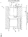
- FIG. 1 is a schematic cross-sectional view of an axial-flow turbine according to some embodiments, showing a part of a cross section including an axis of a turbine rotor (meridional section).
- FIG. 2 is a schematic perspective view of a part of a turbine rotor blade row according to some embodiments.
- An axial-flow turbine 1 includes a plurality of turbine stages 2 disposed in an axial direction of a hub 18.
- Each turbine stage 2 includes a turbine rotor blade row 6 including a plurality of turbine rotor blades 4, and a turbine stator blade row 14 including a plurality of turbine stator blades 12 disposed between an outer ring 8 and an inner ring 10 and disposed upstream of the turbine rotor blade row 6.
- the plurality of turbine rotor blades 4 is disposed along a circumferential direction of the hub 18 (see FIG. 1 ) on a circumferential surface 20 of the hub 18, with inter-blade flow channels 16 formed between the turbine rotor blades 4.
- a typical turbine rotor blade row is designed to have an inter-blade flow channel formed with a flow-channel width monotonically decreasing regardless of the position in the radial direction of the hub from the inlet toward the outlet of the inter-blade flow channel, for the purpose of suppressing separation.
- the inter-blade flow channel 16 described below has a cross-sectional shape that includes a throat portion between the inlet and the outlet of the inter-blade flow channel 16 in the axial direction of the hub 18, where the cross-sectional shape is taken in a direction perpendicular to the radial direction of the hub 18.
- the shape of the inter-blade flow channel 16 will be described below in detail.
- the inter-blade flow channel 16 has the first cross-sectional shape at the first position r1 (see FIG. 1 ) in the radial direction of the hub 18 and the second cross-sectional shape at the second position r2 (see FIG. 1 ) farther from the hub 18 than the first position r1 is in the radial direction of the hub 18.
- the first and second cross-sectional shapes are taken in a direction perpendicular to the radial direction of the hub 18.
- blade-height ratio a value obtained by dividing the distance from the circumferential surface 20 of the hub 18 in the radial direction of the hub 18 by the blade height of the turbine rotor blade 4 in the radial direction of the hub 18 as "blade-height ratio"
- the blade-height ratio R1 at the first position that defines the first cross-sectional shape and the blade-height ratio R2 at the second position that defines the second cross-sectional shape described below satisfy relationships 0 ⁇ R1 ⁇ 0.3 and 0.3 ⁇ R2 ⁇ 0.7, respectively, for instance.
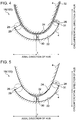
- FIGs. 3 to 5 are each a schematic cross-sectional view of an example of the first cross-sectional shape according to some embodiments.
- FIGs. 6 to 8 are each a schematic cross-sectional view of an example of the second cross-sectional shape according to some embodiments.
- FIGs. 3 to 8 to explain the cross-sectional shape of the inter-blade flow channel 16, depicted are the pressure surface 22 of one of adjacent turbine rotor blades 4 and the suction surface 24 of the other one of the adjacent turbine rotor blades 4.
- the first cross-sectional shape 100 has a throat portion 30 at the position E between the inlet 26 and the outlet 28 of the inter-blade flow channel 16 in the axial direction of the hub 18.
- the inlet of the inter-blade flow channel refers to a portion at the minimum distance represented by the diameter of a virtual inscribed circle touching the leading edge 29 of a turbine rotor blade 4 and the suction surface 24 of an adjacent turbine rotor blade 4, while “the outlet 28 of the inter-blade flow channel 16" refers to a portion at the minimum distance represented by the diameter of a virtual inscribed circle touching the trailing edge 31 of a turbine rotor blade 4 and the suction surface 24 of an adjacent turbine rotor blade 4. Furthermore, “the throat portion” refers to a portion at which the flow-channel width reaches its minimum, the flow-channel width represented by the diameter of a virtual inscribed circle touching the inter-blade flow channel 16 in the axial direction of the hub 18.
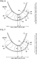
- the inter-blade flow channel 16 is formed to satisfy an expression A1/B1>A2/B2, where A1 is the flow-channel width of the first cross-sectional shape 100 at the outlet 28 of the inter-blade flow channel 16, B1 is the flow-channel width of the first cross-sectional shape 100 at the throat portion 30, as depicted in FIGs. 3 to 5 , and A2 is the flow-channel width of the second cross-sectional shape 200 at the outlet 28 of the inter-blade flow channel 16 and B2 is the flow-channel width of the second cross-sectional shape 200 at the same position E as the throat portion 30 in the axial direction of the hub 18, as depicted in FIGs. 6 to 8 .
- the ratio A1/B1 of the flow-channel width A1 of the first cross-sectional shape 100 at the outlet 28 of the inter-blade flow channel 16 to the flow-channel width B1 of the first cross-sectional shape 100 at the throat portion 30 is greater than the ratio A2/B2 of the flow-channel width A2 of the second cross-sectional shape 200 at the outlet 28 of the inter-blade flow channel 16 to the flow-channel width B2 of the second cross-sectional shape 200 at the same position E as the throat portion 30 in the axial direction of the hub 18.
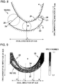
- FIG. 9 is a diagram showing the first cross-sectional shape 100 in the inter-blade flow channel 16 satisfying the above condition (A1/B1>A2/B2), along with an analysis result of the Mach number of a fluid at each position in the flow channel.
- FIG. 10 is a chart of an analysis result on a relationship between a statistic pressure and a blade-height ratio, at each of the positions H, I, J, and K in the axial direction of the hub 18 depicted in FIG. 9 .
- the dotted line, the single-dotted line, the dashed chain line, and the solid line represent analysis results at the positions H, I, J, and K in the axial direction, respectively.
- the Mach number of the fluid generally increases from the inlet 26 toward the outlet 28 of the inter-blade flow channel 16. Furthermore, as depicted in FIG. 10 , in the inter-blade flow channel 16, the statistic pressure decreases from the inlet 26 toward the outlet 28 of the inter-blade flow channel 16 (in the order of the positions H, I, J, K in the axial direction of the hub 18), regardless of the blade-height ratio.
- the inter-blade flow channel 16 functions properly as a velocity-increasing flow channel to suppress a secondary flow.
- FIG. 11A is a schematic diagram of an analysis result on a limiting streamline (a streamline at a position infinitely close to the pressure surface 22 of the rotor blade 4) at the pressure side of the rotor blade in the inter-blade flow channel 16 satisfying the above condition (A1/B1>A2/B2).
- FIG. 11B is a schematic diagram of an analysis result on a limiting streamline at the pressure side of the rotor blade in the above described typical inter-blade flow channel.
- a typical inter-blade flow channel is formed to have a flow-channel width that monotonically decreases from the inlet toward the outlet of the inter-blade flow channel in the cross-section at each position in the radial direction of the hub (the same applies hereinafter).
- the limit streamline of the inter-blade flow channel 16 shown in FIG. 11A is relatively close to a straight line along the axial direction of the hub. The reason is that, the inter-blade flow channel 16 satisfies the above condition (A1/B1>A2/B2), and thereby a pressure gradient in the radial direction of the hub inside the inter-blade flow channel 16 is in such a direction that suppresses a secondary flow as described below.
- M is a point on the position E in the axial direction of the hub and also on the position r1 in the radial direction of the hub (a point where the throat portion 30 is disposed)
- N is a point on the position E in the axial direction of the hub and also on the position r2 in the radial direction of the hub.
- the pressure differential ⁇ P obtained by subtracting the pressure of the point M from the pressure of the point N in FIG. 11A is greater in the positive direction than the pressure differential ⁇ P obtained by subtracting the pressure of the point M from the pressure of the point N in the typical inter-blade flow channel shown in FIG. 11B .
- points M, N are also referred to as points M, N to indicate the same positions as the points M, N in FIG. 11A , for the sake of convenience.
- the velocity of the fluid can be suitably increased at a position closer to the inlet 26 than the throat portion 30 is, and thereby it is possible to suppress occurrence of separation at a position closer to the inlet 26 than the throat portion 30 is.
- the velocity may decrease in the flow channel at the outlet 28 side of the throat portion 30, which makes it difficult to suppress secondary-flow loss.
- At least one partial region in the axial direction of the hub 18 is defined by a buildup portion 32 formed by welding on at least one of the turbine rotor blade 4 or the hub 18 .
- the throat portion 30 of the first cross-sectional shape 100 may be disposed in the at least one partial region. Accordingly, it is possible to improve the performance of the turbine rotor blade row 6, and to enhance the design flexibility of the airfoil of the turbine rotor blade 4.
- the buildup portion 32 may be formed on the pressure surface 22 of one of adjacent two turbine rotor blades 4, or on the suction surface 24 of the other one of the turbine rotor blades 4. Furthermore, the buildup portion 32 may be formed over the entire region from the inlet 26 to the outlet 28 in the axial direction of the hub as depicted in FIG. 4 , or partially in the axial direction of the hub as depicted in FIG. 5 .
- the second cross-sectional shape may include a throat portion 34 between the inlet 26 and the outlet 28, as depicted in FIG. 6 for instance.
- a throat portion 34 between the inlet 26 and the outlet 28, as depicted in FIG. 6 for instance.
- the throat portion 34 of the second cross-sectional shape 200 may be disposed closer to the outlet 28 of the inter-blade flow channel 16 in the axial direction of the hub 18 than the throat portion 30 of the first cross-sectional shape 100 is.
- the position F of the throat portion 34 may be disposed closer to the outlet 28 than the position E of the throat portion 30 is.
- the above-described differential pressure ⁇ P can be increased in the positive direction more easily at the position E where the throat portion 30 is disposed in the axial direction of the hub 18, and thereby uplift of the secondary flow from the surface of the hub flowing outward in the radial direction is effectively suppressed.
- the second cross-sectional shape 200 may have a flow-channel width that monotonically decreases and then stays constant from the inlet 26 toward the outlet 28. Also with this shape, the inter-blade flow channel 16 satisfies the above condition (A1/B1>A2/B2), which suppresses uplift of the secondary flow outward in the radial direction of the hub 18.
- the flow-channel width monotonically decreases to the position G closer to the outlet 28 than the position E in the axial direction of the hub 18, and then is maintained at A2.
- the above-described differential pressure ⁇ P can be increased in the positive direction more easily at the position E where the throat portion 30 is disposed in the axial direction of the hub 18, and thereby uplift of the secondary flow from the surface of the hub flowing outward in the radial direction is effectively suppressed. Accordingly, it is possible to improve the performance of the turbine rotor blade row 6 effectively.
- the second cross-sectional shape 200 may have a flow-channel width that monotonically decreases from the inlet 26 toward the outlet 28.
- the above-described differential pressure ⁇ P can be increased in the positive direction more easily at the position E where the throat portion 30 is disposed in the axial direction of the hub, and thereby uplift of the secondary flow from the surface of the hub flowing outward in the radial direction is effectively suppressed.
- each of the turbine rotor blades 4, depicted in FIGs. 1 to 8 for instance, may have a constant cross-sectional shape (cross-sectional profile) perpendicular to the blade-height direction from the blade-root portion 36 (see FIG. 2 ) to the blade tip portion 38 (see FIG. 2 ).
- each of the plurality of turbine rotor blades 4 may be a parallel blade (two-dimensional blades).
- each of the plurality of turbine rotor blades 4 is a parallel blade
- the above described first cross-sectional shape 100 and second cross-sectional shape 200 are disposed at different positions from each other in the radial direction of the hub, and thus it is possible to form the turbine rotor blade row 6 satisfying the above condition (A1/B1>A2/B2) by taking advantage of the difference in perimeter. Accordingly, by employing parallel blades as the plurality of turbine rotor blades 4, it is possible to facilitate production (manufacture), improve performance, and reduce production costs for the turbine rotor blades 4.
- P 1S , P 2S , P 0 are each a static pressure or a total pressure at the corresponding position depicted in FIG. 1 .
- P 1S is a static pressure at the inlet of the rotor blade at the first position r1 in the radial direction of the hub
- P 2S is a static pressure at the outlet of the rotor blade at the first position r1 in the radial direction of the hub
- P 0 is a total pressure at the inlet of the stator blade.
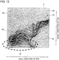
- FIG. 12 depicted is a characteristic swirl 40 that occurs in the inter-blade flow channel 16 in a meridional cross-section of the inter-blade flow channel.
- the swirl 40 moves from a region R on the hub side of the inter-blade flow channel 16, the region R being relatively close to the inlet 26, outwardly in the radial direction of the hub (in the direction of the arrow 42) in a spiral pattern, accompanied by a reverse flow.
- the degree of reaction is small, the differential pressure before and after the inter-blade flow channel 16 is also small, and thus the pressure gradient may reverse to generate a reverse flow in a region in the inter-blade flow channel.
- the degree of reaction is no more than 0.25, the characteristic swirl 40 is likely to occur as described above.
- the differential pressure ⁇ P in the radial direction of the hub increases in the positive direction inside the inter-blade flow channel 16 as compared to the typical inter-blade flow channel, as described above with reference to FIGs. 11A and 11B , and thus uplift of the characteristic swirl 40 from the surface of the hub flowing outward in the radial direction of the hub can also be suppressed. Accordingly, it is possible to improve the performance of the turbine rotor blade row 6 effectively.
- the axial-flow turbine 1 depicted in FIG. 1 for instance may be configured to operate with the Mach number of a fluid in the entire region of the inter-blade flow channel 16 being less than 1.0. Also in such an axial-flow turbine configured to operate at a subsonic speed, the performance of the turbine rotor blade row 6 can be improved effectively by the inter-blade flow channel 16 formed to satisfy the above condition (A1/B1>A2/B2).
- a ratio H/W of the blade height H (see FIG. 1 ) in the radial direction of the hub to the blade width W (see FIG. 1 ) in the axial direction of the hub may be less than 1.0.
- the turbine rotor blade 4 has a relatively low aspect ratio (if H/W is less than 1.0) and the shape of the inter-blade flow channel 16 is determined simply without any conditions, interference may take place between the above described swirl 40 (see FIG. 12 ) from the hub side and the secondary flow at the tip side, and loss is likely to be generated.
- the inter-blade flow channel 16 formed to satisfy the above condition (A1/B1>A2/B2), it is possible to suppress such interference between the swirl 40 and the secondary flow at the tip side. Accordingly, it is possible to improve the performance of the turbine rotor blade row 6 effectively.
- the aspect ratio (H/W) may be greater than 1.0.
- the degree of reaction has a distribution in the radial direction, which is higher at the tip side and lower at the hub side.
- the aspect ratio is greater than 1.0, a secondary flow and separation are likely to occur at the hub side.
- the inter-blade flow channel 16 formed to satisfy the above condition (A1/B1>A2/B2) it is possible to suppress occurrence of a secondary flow and separation, and to improve the performance of the turbine rotor blade row 6 effectively.
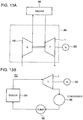
- the axial-flow turbine 1 may be applied to a turbocharger 44, for instance. More specifically, the turbine rotor blade row 6 including a plurality of turbine rotor blades 4 forming the above described inter-blade flow channel 16 may be applied to a turbine 1 for driving a compressor 48 for pressurizing intake air to be fed to an internal combustion engine 46. In this case, the axial-flow turbine 1 is driven by exhaust gas from the internal combustion engine 46 to generate power, which drives the compressor 48. The axial-flow turbine 1 may be further coupled to a generator 50.
- the axial-flow turbine 1 in the embodiment depicted in FIG. 1 is of the Rateau type in which a turbine stage 2 includes a single turbine stator blade row 14 and a single turbine rotor blade row 6, the number of turbine stator blade rows 14 and the number of turbine rotor blade rows 6 in a single turbine stage 2 are not particularly limited.
- the axial-flow turbine 1 may be of the Curtis type in which a turbine stage 2 includes a single turbine stator blade row 14 and two turbine rotor blade rows 6 (or, two turbine stator blade rows 14 and three turbine rotor blade rows 6).
- the axial-flow turbine 1 depicted in FIG. 1 may be a steam turbine, or a gas turbine.
- the axial-flow turbine 1 may be applied to a steam turbine in a power-generation facility 52.
- the power-generation facility 52 depicted in FIG. 13B includes a boiler 54 for generating steam, a steam turbine 1 driven by steam generated by the boiler 54, a generator 50 coupled to the steam turbine 1, a condenser 56 for cooling and condensing exhaust gas from the steam turbine 1, and a pump 58 for supplying the boiler 54 with water generated through condensation by the condenser 56.
- application of the axial-flow turbine 1 is not particularly limited, and may be a turbine in a ship, or a fixed turbine for private power generation.
Landscapes
- Engineering & Computer Science (AREA)
- Mechanical Engineering (AREA)
- General Engineering & Computer Science (AREA)
- Physics & Mathematics (AREA)
- Fluid Mechanics (AREA)
- Turbine Rotor Nozzle Sealing (AREA)
Description
- The present disclosure relates to a turbine rotor blade row, a turbine stage, and an axial-flow turbine.
- A turbine such as a steam turbine and a gas turbine includes a plurality of turbine rotor blades disposed along a circumferential direction of a hub, with inter-blade flow channels formed between the turbine rotor blades. A fluid passes through the inter-blade flow channels, and a centrifugal force generated due to the velocity energy of the fluid and a pressure differential between a pressure-surface side and a suction-surface side of a turbine rotor blade are balanced in the vicinity of a mean (intermediate) position of the turbine rotor blade. On the other hand, the flow velocity is low and thus the centrifugal force decreases at a boundary layer of the flow in the vicinity of the hub. Accordingly, a secondary flow (cross flow) of the fluid may be generated, flowing from the pressure-surface side with a high pressure toward the suction-surface side with a low pressure. In typical turbine rotor blades, such a secondary flow generates loss (secondary-flow loss) which accounts significantly for power loss.
-
JP 2003-20904A JP 2003-20904A -
GB 1489095A -
EP 1712737 A1 discloses a turbine rotor blade on which the preamble portion ofclaim 1 is based. - Typical turbine rotor blades are configured such that the width of an inter-blade flow channel gradually narrows from the inlet toward the outlet of the inter-blade flow channel. The axial-flow turbine blade in
JP 2003-20904A - If the flow-channel width gradually narrows from the inlet toward the outlet of an inter-blade flow channel as in the above-mentioned configuration, separation of a flow could be suppressed to some extent, but a flow is still likely to separate at the upstream side in the inter-blade flow channel and a secondary flow is likely to occur and develop.
- In view of the above issue, an object of at least one embodiment of the present invention is to provide a turbine rotor blade row, a turbine stage, and an axial-flow turbine, whereby it is possible to suppress secondary-flow loss to improve performance of a turbine rotor blade row.
-
- (1) A turbine rotor blade row according to the present invention comprises the features of
claim 1, including: a plurality of turbine rotor blades disposed along a circumferential direction of a hub with an inter-blade flow channel formed between the turbine rotor blades. The inter-blade flow channel has a first cross-sectional shape perpendicular to a radial direction of the hub at a first position in the radial direction, and a second cross-sectional shape perpendicular to the radial direction of the hub at a second position farther from the hub than the first position in the radial direction. The first cross-sectional shape has a throat portion between an inlet and an outlet of the inter-blade flow channel in an axial direction of the hub. An expression A1/B1>A2/B2 is satisfied, where A1 is a flow-channel width of the first cross-sectional shape at the outlet of the inter-blade flow channel, B1 is a flow-channel width of the first cross-sectional shape at the throat portion, A2 is a flow-channel width of the second cross-sectional shape at the outlet of the inter-blade flow channel, and B2 is a flow-channel width of the second cross-sectional shape at the same position as the throat portion in the axial direction of the hub.
With the turbine rotor blade row having the above configuration (1), the first cross-sectional shape has a throat portion between the inlet and the outlet of the inter-blade flow channel in the axial direction of the hub, and thus the flow has a higher velocity at the inlet side of the throat portion, which makes it possible to suppress occurrence of separation at the inlet side of the throat portion. If such a throat portion is simply provided without any conditions, the velocity may decrease in the flow channel at the outlet side of the throat portion, which makes it difficult to suppress secondary-flow loss. However, with the above turbine rotor blade row (1), the condition A1/B1>A2/B2 is satisfied as well, and thus it is possible to form a pressure gradient in the radial direction of the hub that suppresses uplift of the secondary flow from the surface of the hub flowing outward in the radial direction of the hub, between the inlet and the outlet of the inter-blade flow channel. Accordingly, it is possible to reduce secondary-flow loss effectively, and improve the performance of the turbine rotor blade row. - (2) In some embodiments, in the above turbine rotor blade row (1), the flow-channel width of the second cross-sectional shape monotonically decreases from the inlet toward the outlet of the inter-blade flow channel.
With the above turbine rotor blade row (2), it is possible to readily form a pressure gradient in the radial direction of the hub that suppresses uplift of the secondary flow from the surface of the hub flowing outward in the radial direction of the hub, between the inlet and the outlet of the inter-blade flow channel. Accordingly, it is possible to reduce secondary-flow loss effectively, and improve the performance of the turbine rotor blade row. - (3) In the turbine rotor blade row (1) according to the invention, the second cross-sectional shape includes a throat portion between the inlet and the outlet of the inter-blade flow channel.
With the above turbine rotor blade row (3), also in a case each of the first cross-sectional shape and the second cross-sectional shape has a throat portion, uplift of the secondary flow flowing outward in the radial direction from the surface of the hub is suppressed by satisfying the above condition (A1/B1>A2/B2). - (4) In the turbine rotor blade row (3) according to the invention, the throat portion of the second cross-sectional shape is disposed closer to the outlet of the inter-blade flow channel in the axial direction of the hub than the throat portion of the first cross-sectional shape is.
With the above turbine rotor blade row (4), even in a case where each of the first cross-sectional shape and the second cross-sectional shape has a throat portion, it is possible to readily form a pressure gradient in the radial direction of the hub that suppresses uplift of the secondary flow from the surface of the hub flowing outward in the radial direction of the hub, between the inlet and the outlet of the inter-blade flow channel. Accordingly, it is possible to reduce secondary-flow loss effectively, and improve the performance of the turbine rotor blade row. - (5) In some embodiments, in the above turbine rotor blade row (1), the second cross-sectional shape has a flow-channel width which decreases monotonically and then stays constant from the inlet toward the outlet of the inter-blade flow channel.
Also with the above turbine rotor blade row (5), uplift of the secondary flow flowing outward in the radial direction from the surface of the hub can be suppressed by satisfying the above condition (A1/B1>A2/B2). - (6) In some embodiments, in the turbine rotor blade row according to any one of the above (1) to (5), each of the plurality of turbine rotor blades has a cross-sectional shape perpendicular to a blade-height direction which is constant from a blade root portion to a blade tip portion.
Even if each of the plurality of turbine blades is a parallel blade as in the above turbine blade row (6), the above described first cross-sectional shape and second cross-sectional shape are disposed at different positions from each other in the radial direction of the hub, and thus it is possible to form the turbine rotor blade row satisfying the above condition by taking advantage of the difference in perimeter. Accordingly, by employing parallel blades as the plurality of turbine rotor blades, it is possible to facilitate production (manufacture), improve performance, and reduce production costs for the turbine rotor blades. - (7) In some embodiments, in the turbine rotor blade row according to any one of the above (1) to (6), the first cross-sectional shape has a flow-channel width defined by a buildup portion formed by welding on at least one of the turbine rotor blade or the hub in at least one partial region in the axial direction of the hub.
With the above turbine rotor blade row (7), it is possible to improve the performance of the turbine rotor blade row, and to enhance the design flexibility of the airfoil of the turbine rotor blade. - (8) In some embodiments, in the above turbine rotor blade row (7), the throat portion of the first cross-sectional shape is disposed in the at least one partial region.
With the above turbine rotor blade row (8), it is possible to easily improve the performance of the turbine rotor blade row, and to enhance the design flexibility of the airfoil of the turbine rotor blade. - (9) In some embodiments, in the turbine rotor blade row according to any one of the above (1) to (8), H/W is less than 1.0 in each of the turbine rotor blades, where W is a blade width in the axial direction of the hub and H is a blade height in the radial direction of the hub.
With the above turbine rotor blade row (9), if the turbine rotor blade has a relatively low aspect ratio (if H/W is less than 1.0) and the shape of the inter-blade flow channel is determined simply without any conditions, interference is likely to take place between the secondary flow from the hub side and the secondary flow from the tip (blade tip) side. On the contrary, with the inter-blade flow channel formed to satisfy the above condition (A1/B1>A2/B2), it is possible to suppress such interference of secondary flows. Accordingly, it is possible to improve the performance of the turbine rotor blade row effectively. - (10) In some embodiments, in the turbine rotor blade row according to any one of the above (1) to (9), a blade-height ratio R1 at the first position and a blade-height ratio R2 at the second position satisfy expressions 0<R1<0.3 and 0.3<R2<0.7, respectively, where a blade-height ratio r is a value obtained by dividing a distance from a surface of the hub in the radial direction of the hub by a blade height of the turbine rotor blade in the radial direction of the hub.
With the above turbine rotor blade row (10), it is possible to suppress uplift of the secondary flow flowing outward in the radial direction from the surface of the hub effectively. - (11) A turbine stage according to at least one embodiment of the present invention comprises: the turbine rotor blade row according to any one of the above (1) to (10); and a turbine stator blade row disposed upstream of the turbine rotor blade row and including a plurality of turbine stator blades.
With the above turbine stage (11), it is possible to reduce secondary-flow loss, and improve the performance of the turbine rotor blade row effectively. - (12) An axial turbine according to at least one embodiment of the present invention comprises a plurality of turbine stages disposed in an axial direction of a hub, and at least one of the turbine stages is the turbine stage according to the above (11).
With the above axial-flow turbine (12), it is possible to reduce secondary-flow loss, and improve the performance of the axial-flow turbine effectively. - (13) In some embodiments, the axial turbine according to the above (12) is configured to operate with a degree of reaction being no more than 0.25 at the first position in the radial direction of the hub. In this case, the degree of reaction may be a negative value.
If the degree of reaction is small, the differential pressure before and after the inter-blade flow channel is also small, and thus the pressure gradient may reverse to generate a reverse flow in a region in the inter-blade flow channel. According to the researches by the present inventors, it was found that a characteristic flow (a swirl flow that moves from a region relatively close to the inlet and on the hub side of the inter-blade flow channel, toward the outer side of the hub in the radial direction in a spiral pattern accompanying a reverse flow) may be generated, typically if the degree of reaction is no more than 0.25. In this regard, with the inter-blade flow channel being formed to satisfy the above condition (A1/B1>A2/B2), it is possible to form a pressure gradient in the radial direction of the hub that suppresses uplift of the characteristic flow from the surface of the hub flowing outward in the radial direction of the hub. Accordingly, it is possible to reduce secondary-flow loss and improve the performance of the axial-flow turbine effectively. - (14) In some embodiments, the axial turbine according to the above (12) or (13) is configured to operate with a Much number of a fluid being less than 1.0 in an entire region of the inter-blade flow channel.
Also in the axial-flow turbine configured to operate at a subsonic speed, with the inter-blade flow channel formed to satisfy the above condition (A1/B1>A2/B2), it is possible to reduce the secondary-flow loss and improve the performance of the turbine rotor blade row effectively. - According to at least one embodiment of the present invention, provided is a turbine rotor blade row, a turbine stage, and an axial-flow turbine, whereby it is possible to suppress secondary-flow loss to improve performance of a turbine rotor blade row.
-
-
FIG. 1 is a schematic cross-sectional view of an axial-flow turbine according to some embodiments, showing a part of a cross section including an axis of a turbine rotor (meridional section). -
FIG. 2 is a schematic perspective view of a part of a turbine rotor blade row according to some embodiments. -
FIG. 3 is a schematic cross-sectional view of an example of the first cross-sectional shape according to some embodiments. -
FIG. 4 is a schematic cross-sectional view of an example of the first cross-sectional shape according to some embodiments. -
FIG. 5 is a schematic cross-sectional view of an example of the first cross-sectional shape according to some embodiments. -
FIG. 6 is a schematic cross-sectional view of an example of the second cross-sectional shape according to some embodiments. -
FIG. 7 is a schematic cross-sectional view of an example of the second cross-sectional shape according to some embodiments. -
FIG. 8 is a schematic cross-sectional view of an example of the second cross-sectional shape according to some embodiments. -
FIG. 9 is a diagram showing the first cross-sectional shape in an inter-blade flow channel satisfying A1/B1>A2/B2 along with an analysis result of the Mach number of a fluid at each position in the flow channel. -
FIG. 10 is a chart of an analysis result on a relationship between a statistic pressure and a position in the blade-height direction, at each of the positions H, I, J, and K in the axial direction of a hub. -
FIG. 11A is a schematic diagram of an analysis result on a limiting streamline at the pressure side of a rotor blade in an inter-blade flow channel that satisfies A1/B1>A2/B2.FIG. 11B is a schematic diagram of an analysis result on a limiting streamline at the pressure side of a rotor blade in a typical inter-blade flow channel. -
FIG. 12 is a diagram of a characteristic swirl that develops inside an inter-blade flow channel. -
FIG. 13A is a diagram of an exemplary configuration where an axial-flow turbine is applied to a turbine of a turbocharger.FIG. 13B is a diagram of an exemplary configuration where an axial-flow turbine is applied to a turbine of a power-generating facility. - Embodiments of the present invention will now be described in detail with reference to the accompanying drawings. It is intended, however, that unless particularly specified, dimensions, materials, shapes, relative positions and the like of components described in the embodiments shall be interpreted as illustrative only and not intended to limit the scope of the present invention.
- For instance, an expression of relative or absolute arrangement such as "in a direction", "along a direction", "parallel", "orthogonal", "centered", "concentric" and "coaxial" shall not be construed as indicating only the arrangement in a strict literal sense, but also includes a state where the arrangement is relatively displaced by a tolerance, or by an angle or a distance whereby it is possible to achieve the same function.
- Further, for instance, an expression of a shape such as a rectangular shape or a cylindrical shape shall not be construed as only the geometrically strict shape, but also includes a shape with unevenness or chamfered corners within the range in which the same effect can be achieved.
- On the other hand, an expression such as "comprise", "include", "have", "contain" and "constitute" are not intended to be exclusive of other components.
-
FIG. 1 is a schematic cross-sectional view of an axial-flow turbine according to some embodiments, showing a part of a cross section including an axis of a turbine rotor (meridional section).FIG. 2 is a schematic perspective view of a part of a turbine rotor blade row according to some embodiments. - An axial-
flow turbine 1 according to some embodiments includes a plurality ofturbine stages 2 disposed in an axial direction of ahub 18. InFIG. 1 , one of the turbine stages 2 is depicted in an enlarged view to simplify the description. Eachturbine stage 2 includes a turbinerotor blade row 6 including a plurality ofturbine rotor blades 4, and a turbine stator blade row 14 including a plurality ofturbine stator blades 12 disposed between an outer ring 8 and aninner ring 10 and disposed upstream of the turbinerotor blade row 6. As depicted inFIG. 2 , the plurality ofturbine rotor blades 4 is disposed along a circumferential direction of the hub 18 (seeFIG. 1 ) on acircumferential surface 20 of thehub 18, withinter-blade flow channels 16 formed between theturbine rotor blades 4. - According to Bernoulli's theorem, if there exists a region where the cross-sectional area of a flow channel (an area of a cross-section perpendicular to the main flow direction of the flow channel) increases from the inlet toward the outlet of the inter-blade flow channel, the pressure of the fluid increases and the velocity of the fluid decreases in the region, which is likely to result in occurrence of separation. Thus, a typical turbine rotor blade row is designed to have an inter-blade flow channel formed with a flow-channel width monotonically decreasing regardless of the position in the radial direction of the hub from the inlet toward the outlet of the inter-blade flow channel, for the purpose of suppressing separation.
- In contrast, the
inter-blade flow channel 16 described below has a cross-sectional shape that includes a throat portion between the inlet and the outlet of theinter-blade flow channel 16 in the axial direction of thehub 18, where the cross-sectional shape is taken in a direction perpendicular to the radial direction of thehub 18. The shape of theinter-blade flow channel 16 will be described below in detail. - The
inter-blade flow channel 16 has the first cross-sectional shape at the first position r1 (seeFIG. 1 ) in the radial direction of thehub 18 and the second cross-sectional shape at the second position r2 (seeFIG. 1 ) farther from thehub 18 than the first position r1 is in the radial direction of thehub 18. The first and second cross-sectional shapes are taken in a direction perpendicular to the radial direction of thehub 18. Defining herein a value obtained by dividing the distance from thecircumferential surface 20 of thehub 18 in the radial direction of thehub 18 by the blade height of theturbine rotor blade 4 in the radial direction of thehub 18 as "blade-height ratio", the blade-height ratio R1 at the first position that defines the first cross-sectional shape and the blade-height ratio R2 at the second position that defines the second cross-sectional shape described below satisfy relationships 0<R1<0.3 and 0.3<R2<0.7, respectively, for instance. - The first and second cross-sectional shapes will now be described with reference to
FIGs. 3 to 8 .FIGs. 3 to 5 are each a schematic cross-sectional view of an example of the first cross-sectional shape according to some embodiments.FIGs. 6 to 8 are each a schematic cross-sectional view of an example of the second cross-sectional shape according to some embodiments. InFIGs. 3 to 8 , to explain the cross-sectional shape of theinter-blade flow channel 16, depicted are thepressure surface 22 of one of adjacentturbine rotor blades 4 and thesuction surface 24 of the other one of the adjacentturbine rotor blades 4. - In some embodiments, as depicted in
FIGs. 3 to 5 for instance, the firstcross-sectional shape 100 has athroat portion 30 at the position E between theinlet 26 and theoutlet 28 of theinter-blade flow channel 16 in the axial direction of thehub 18. Herein, "the inlet of the inter-blade flow channel" refers to a portion at the minimum distance represented by the diameter of a virtual inscribed circle touching the leadingedge 29 of aturbine rotor blade 4 and thesuction surface 24 of an adjacentturbine rotor blade 4, while "theoutlet 28 of theinter-blade flow channel 16" refers to a portion at the minimum distance represented by the diameter of a virtual inscribed circle touching the trailingedge 31 of aturbine rotor blade 4 and thesuction surface 24 of an adjacentturbine rotor blade 4. Furthermore, "the throat portion" refers to a portion at which the flow-channel width reaches its minimum, the flow-channel width represented by the diameter of a virtual inscribed circle touching theinter-blade flow channel 16 in the axial direction of thehub 18. - The
inter-blade flow channel 16 is formed to satisfy an expression A1/B1>A2/B2, where A1 is the flow-channel width of the firstcross-sectional shape 100 at theoutlet 28 of theinter-blade flow channel 16, B1 is the flow-channel width of the firstcross-sectional shape 100 at thethroat portion 30, as depicted inFIGs. 3 to 5 , and A2 is the flow-channel width of the secondcross-sectional shape 200 at theoutlet 28 of theinter-blade flow channel 16 and B2 is the flow-channel width of the secondcross-sectional shape 200 at the same position E as thethroat portion 30 in the axial direction of thehub 18, as depicted inFIGs. 6 to 8 . In other words, the ratio A1/B1 of the flow-channel width A1 of the firstcross-sectional shape 100 at theoutlet 28 of theinter-blade flow channel 16 to the flow-channel width B1 of the firstcross-sectional shape 100 at thethroat portion 30 is greater than the ratio A2/B2 of the flow-channel width A2 of the secondcross-sectional shape 200 at theoutlet 28 of theinter-blade flow channel 16 to the flow-channel width B2 of the secondcross-sectional shape 200 at the same position E as thethroat portion 30 in the axial direction of thehub 18. -
FIG. 9 is a diagram showing the firstcross-sectional shape 100 in theinter-blade flow channel 16 satisfying the above condition (A1/B1>A2/B2), along with an analysis result of the Mach number of a fluid at each position in the flow channel.FIG. 10 is a chart of an analysis result on a relationship between a statistic pressure and a blade-height ratio, at each of the positions H, I, J, and K in the axial direction of thehub 18 depicted inFIG. 9 . InFIG. 10 , the dotted line, the single-dotted line, the dashed chain line, and the solid line represent analysis results at the positions H, I, J, and K in the axial direction, respectively. - As shown in
FIG. 9 , in the firstcross-sectional shape 100, the Mach number of the fluid generally increases from theinlet 26 toward theoutlet 28 of theinter-blade flow channel 16. Furthermore, as depicted inFIG. 10 , in theinter-blade flow channel 16, the statistic pressure decreases from theinlet 26 toward theoutlet 28 of the inter-blade flow channel 16 (in the order of the positions H, I, J, K in the axial direction of the hub 18), regardless of the blade-height ratio. Accordingly, even though the firstcross-sectional shape 100 has thethroat portion 30 between theinlet 26 and theoutlet 28 of the inter-blade flow channel 16 (i.e., there exists a region where the flow-channel width increases from thethroat portion 30 toward the downstream side), theinter-blade flow channel 16 functions properly as a velocity-increasing flow channel to suppress a secondary flow. - The reasons why the above effect can be achieved will now be discussed with reference to
FIGs. 11A and 11B. FIG. 11A is a schematic diagram of an analysis result on a limiting streamline (a streamline at a position infinitely close to thepressure surface 22 of the rotor blade 4) at the pressure side of the rotor blade in theinter-blade flow channel 16 satisfying the above condition (A1/B1>A2/B2).FIG. 11B is a schematic diagram of an analysis result on a limiting streamline at the pressure side of the rotor blade in the above described typical inter-blade flow channel. It should be noted that, a typical inter-blade flow channel is formed to have a flow-channel width that monotonically decreases from the inlet toward the outlet of the inter-blade flow channel in the cross-section at each position in the radial direction of the hub (the same applies hereinafter). - Comparing
FIGs. 11A and 11B , the limit streamline of theinter-blade flow channel 16 shown inFIG. 11A is relatively close to a straight line along the axial direction of the hub. The reason is that, theinter-blade flow channel 16 satisfies the above condition (A1/B1>A2/B2), and thereby a pressure gradient in the radial direction of the hub inside theinter-blade flow channel 16 is in such a direction that suppresses a secondary flow as described below. - In the
inter-blade flow channel 16 illustrated inFIG. 11A , M is a point on the position E in the axial direction of the hub and also on the position r1 in the radial direction of the hub (a point where thethroat portion 30 is disposed), and N is a point on the position E in the axial direction of the hub and also on the position r2 in the radial direction of the hub. The pressure differential ΔP obtained by subtracting the pressure of the point M from the pressure of the point N inFIG. 11A is greater in the positive direction than the pressure differential ΔP obtained by subtracting the pressure of the point M from the pressure of the point N in the typical inter-blade flow channel shown inFIG. 11B . Accordingly, even if a secondary flow occurs on the surface of the hub, a positive increase in the pressure differential ΔP suppresses uplift of the secondary flow from the surface of the hub flowing outward in the radial direction of the hub. This effect improves the performance of the turbinerotor blade row 6. - It should be noted that, although a typical inter-blade flow channel does not have the
throat portion 30, the points inFIG. 11B are also referred to as points M, N to indicate the same positions as the points M, N inFIG. 11A , for the sake of convenience. - Furthermore, if the first
cross-sectional shape 100 of theinter-blade flow channel 16 has thethroat portion 30, the velocity of the fluid can be suitably increased at a position closer to theinlet 26 than thethroat portion 30 is, and thereby it is possible to suppress occurrence of separation at a position closer to theinlet 26 than thethroat portion 30 is. However, if such athroat portion 30 is simply provided without any conditions, the velocity may decrease in the flow channel at theoutlet 28 side of thethroat portion 30, which makes it difficult to suppress secondary-flow loss. In this regard, with the above condition A1/B1>A2/B2 being satisfied, it is possible to form a pressure gradient in the radial direction of the hub that suppresses uplift of the secondary flow from the surface of the hub flowing outward in the radial direction of the hub. Accordingly, it is possible to reduce the secondary-flow loss effectively and to improve the performance of the turbine rotor blade row while suppressing occurrence of separation at a position closer to theinlet 26 than thethroat portion 30 is. - In some embodiments, with the first
cross-sectional shape 100 depicted inFIGs. 4 and 5 for instance, at least one partial region in the axial direction of thehub 18 is defined by abuildup portion 32 formed by welding on at least one of theturbine rotor blade 4 or thehub 18 . In this case, thethroat portion 30 of the firstcross-sectional shape 100 may be disposed in the at least one partial region. Accordingly, it is possible to improve the performance of the turbinerotor blade row 6, and to enhance the design flexibility of the airfoil of theturbine rotor blade 4. - The
buildup portion 32 may be formed on thepressure surface 22 of one of adjacent twoturbine rotor blades 4, or on thesuction surface 24 of the other one of theturbine rotor blades 4. Furthermore, thebuildup portion 32 may be formed over the entire region from theinlet 26 to theoutlet 28 in the axial direction of the hub as depicted inFIG. 4 , or partially in the axial direction of the hub as depicted inFIG. 5 . - The second cross-sectional shape according to an embodiment may include a
throat portion 34 between theinlet 26 and theoutlet 28, as depicted inFIG. 6 for instance. As described above, also in a case where the firstcross-sectional shape 100 and the secondcross-sectional shape 200 have therespective throat portions hub 18 can be suppressed by satisfying the above condition (A1/B1>A2/B2). - Furthermore, in this case, the
throat portion 34 of the secondcross-sectional shape 200 may be disposed closer to theoutlet 28 of theinter-blade flow channel 16 in the axial direction of thehub 18 than thethroat portion 30 of the firstcross-sectional shape 100 is. In other words, in the axial direction of thehub 18, the position F of thethroat portion 34 may be disposed closer to theoutlet 28 than the position E of thethroat portion 30 is. In this way, the above-described differential pressure ΔP can be increased in the positive direction more easily at the position E where thethroat portion 30 is disposed in the axial direction of thehub 18, and thereby uplift of the secondary flow from the surface of the hub flowing outward in the radial direction is effectively suppressed. - In an embodiment, the second
cross-sectional shape 200, depicted inFIG. 7 for instance, may have a flow-channel width that monotonically decreases and then stays constant from theinlet 26 toward theoutlet 28. Also with this shape, theinter-blade flow channel 16 satisfies the above condition (A1/B1>A2/B2), which suppresses uplift of the secondary flow outward in the radial direction of thehub 18. - Specifically, as for the second cross-sectional shape depicted in
FIG. 7 , the flow-channel width monotonically decreases to the position G closer to theoutlet 28 than the position E in the axial direction of thehub 18, and then is maintained at A2. In this way, the above-described differential pressure ΔP can be increased in the positive direction more easily at the position E where thethroat portion 30 is disposed in the axial direction of thehub 18, and thereby uplift of the secondary flow from the surface of the hub flowing outward in the radial direction is effectively suppressed. Accordingly, it is possible to improve the performance of the turbinerotor blade row 6 effectively. - In an embodiment, the second
cross-sectional shape 200, depicted inFIG. 8 for instance, may have a flow-channel width that monotonically decreases from theinlet 26 toward theoutlet 28. In this way, the above-described differential pressure ΔP can be increased in the positive direction more easily at the position E where thethroat portion 30 is disposed in the axial direction of the hub, and thereby uplift of the secondary flow from the surface of the hub flowing outward in the radial direction is effectively suppressed. - In some embodiments, each of the
turbine rotor blades 4, depicted inFIGs. 1 to 8 for instance, may have a constant cross-sectional shape (cross-sectional profile) perpendicular to the blade-height direction from the blade-root portion 36 (seeFIG. 2 ) to the blade tip portion 38 (seeFIG. 2 ). In other words, each of the plurality ofturbine rotor blades 4 may be a parallel blade (two-dimensional blades). - Even if each of the plurality of
turbine rotor blades 4 is a parallel blade, the above described firstcross-sectional shape 100 and secondcross-sectional shape 200 are disposed at different positions from each other in the radial direction of the hub, and thus it is possible to form the turbinerotor blade row 6 satisfying the above condition (A1/B1>A2/B2) by taking advantage of the difference in perimeter. Accordingly, by employing parallel blades as the plurality ofturbine rotor blades 4, it is possible to facilitate production (manufacture), improve performance, and reduce production costs for theturbine rotor blades 4. - Furthermore, the smaller the degree of reaction (a ratio of the heat drop in a turbine rotor blade to the heat drop in a turbine stage) is, the more the secondary flow is likely to occur. In this regard, the present inventors found that a characteristic swirl may occur typically if the degree of reaction is no more than 0.25. In the present specification, a degree of reaction is a value defined as follows.

FIG. 1 . Specifically, P1S is a static pressure at the inlet of the rotor blade at the first position r1 in the radial direction of the hub, P2S is a static pressure at the outlet of the rotor blade at the first position r1 in the radial direction of the hub, and P0 is a total pressure at the inlet of the stator blade. - In
FIG. 12 , depicted is acharacteristic swirl 40 that occurs in theinter-blade flow channel 16 in a meridional cross-section of the inter-blade flow channel. As shown inFIG. 12 , theswirl 40 moves from a region R on the hub side of theinter-blade flow channel 16, the region R being relatively close to theinlet 26, outwardly in the radial direction of the hub (in the direction of the arrow 42) in a spiral pattern, accompanied by a reverse flow. - If the degree of reaction is small, the differential pressure before and after the
inter-blade flow channel 16 is also small, and thus the pressure gradient may reverse to generate a reverse flow in a region in the inter-blade flow channel. Thus, typically if the degree of reaction is no more than 0.25, thecharacteristic swirl 40 is likely to occur as described above. - In this regard, in the
inter-blade flow channel 16 formed to satisfy the above condition (A1/B1>A2/B2), the differential pressure ΔP in the radial direction of the hub increases in the positive direction inside theinter-blade flow channel 16 as compared to the typical inter-blade flow channel, as described above with reference toFIGs. 11A and 11B , and thus uplift of thecharacteristic swirl 40 from the surface of the hub flowing outward in the radial direction of the hub can also be suppressed. Accordingly, it is possible to improve the performance of the turbinerotor blade row 6 effectively. - In some embodiments, the axial-
flow turbine 1 depicted inFIG. 1 for instance may be configured to operate with the Mach number of a fluid in the entire region of theinter-blade flow channel 16 being less than 1.0. Also in such an axial-flow turbine configured to operate at a subsonic speed, the performance of the turbinerotor blade row 6 can be improved effectively by theinter-blade flow channel 16 formed to satisfy the above condition (A1/B1>A2/B2). - In some embodiments, for each of the
turbine rotor blades 4 depicted inFIGs. 1 to 8 for instance, a ratio H/W of the blade height H (seeFIG. 1 ) in the radial direction of the hub to the blade width W (seeFIG. 1 ) in the axial direction of the hub may be less than 1.0. - If the
turbine rotor blade 4 has a relatively low aspect ratio (if H/W is less than 1.0) and the shape of theinter-blade flow channel 16 is determined simply without any conditions, interference may take place between the above described swirl 40 (seeFIG. 12 ) from the hub side and the secondary flow at the tip side, and loss is likely to be generated. On the contrary, with theinter-blade flow channel 16 formed to satisfy the above condition (A1/B1>A2/B2), it is possible to suppress such interference between theswirl 40 and the secondary flow at the tip side. Accordingly, it is possible to improve the performance of the turbinerotor blade row 6 effectively. - In some embodiments, for each of the
turbine rotor blades 4 depicted inFIGs. 1 to 8 for instance, the aspect ratio (H/W) may be greater than 1.0. - The degree of reaction has a distribution in the radial direction, which is higher at the tip side and lower at the hub side. Thus, if the aspect ratio is greater than 1.0, a secondary flow and separation are likely to occur at the hub side. In this regard, with the
inter-blade flow channel 16 formed to satisfy the above condition (A1/B1>A2/B2), it is possible to suppress occurrence of a secondary flow and separation, and to improve the performance of the turbinerotor blade row 6 effectively. - In some embodiments, as depicted in
FIG. 13A , the axial-flow turbine 1 (seeFIG. 1 ) may be applied to a turbocharger 44, for instance. More specifically, the turbinerotor blade row 6 including a plurality ofturbine rotor blades 4 forming the above describedinter-blade flow channel 16 may be applied to aturbine 1 for driving acompressor 48 for pressurizing intake air to be fed to aninternal combustion engine 46. In this case, the axial-flow turbine 1 is driven by exhaust gas from theinternal combustion engine 46 to generate power, which drives thecompressor 48. The axial-flow turbine 1 may be further coupled to agenerator 50. - In a machine that has load fluctuation (flow-rate fluctuation) like the turbocharger 44 of the
internal combustion engine 46, an inflow angle of a fluid with respect to the rotor blade changes, and thus it is difficult to suppress a secondary flow and separation in the inter-blade flow channel. On the other hand, with theinter-blade flow channel 16 formed to satisfy the above condition (A1/B1>A2/B2) applied, it is possible to suppress a secondary flow and separation in the inter-blade flow channel even if the inflow angle changes. Thus, it is possible to suppress a secondary flow and separation effectively regardless of load fluctuation, and thereby the robust characteristic improves. - While the axial-
flow turbine 1 in the embodiment depicted inFIG. 1 is of the Rateau type in which aturbine stage 2 includes a single turbine stator blade row 14 and a single turbinerotor blade row 6, the number of turbine stator blade rows 14 and the number of turbinerotor blade rows 6 in asingle turbine stage 2 are not particularly limited. For instance, the axial-flow turbine 1 may be of the Curtis type in which aturbine stage 2 includes a single turbine stator blade row 14 and two turbine rotor blade rows 6 (or, two turbine stator blade rows 14 and three turbine rotor blade rows 6). - Furthermore, the axial-
flow turbine 1 depicted inFIG. 1 may be a steam turbine, or a gas turbine. For instance, as depicted inFIG. 13B , the axial-flow turbine 1 may be applied to a steam turbine in a power-generation facility 52. The power-generation facility 52 depicted inFIG. 13B includes aboiler 54 for generating steam, asteam turbine 1 driven by steam generated by theboiler 54, agenerator 50 coupled to thesteam turbine 1, acondenser 56 for cooling and condensing exhaust gas from thesteam turbine 1, and apump 58 for supplying theboiler 54 with water generated through condensation by thecondenser 56. Furthermore, application of the axial-flow turbine 1 is not particularly limited, and may be a turbine in a ship, or a fixed turbine for private power generation. - Embodiments of the present invention were described in detail above, but the present invention is not limited thereto, and various amendments and modifications may be implemented.
-
- 1
- Axial-flow turbine
- 2
- Turbine stage
- 4
- Turbine rotor blade
- 6
- Turbine rotor blade row
- 8
- Outer ring
- 10
- Inner ring
- 12
- Turbine stator blade
- 14
- Turbine stator blade row
- 16
- Inter-blade flow channel
- 18
- Hub
- 20
- Circumferential surface
- 22
- Pressure surface
- 24
- Suction surface
- 26
- Inlet
- 28
- Outlet
- 29
- Leading edge
- 30
- Throat portion
- 31
- Trailing edge
- 32
- Buildup portion
- 34
- Throat portion
- 36
- Blade root portion
- 38
- Blade tip portion
- 40
- Swirl
- 42
- Arrow
- 44
- Turbocharger
- 46
- Internal combustion engine
- 48
- Compressor
- 50
- Generator
- 52
- Power-generation facility
- 54
- Boiler
- 56
- Condenser
- 58
- Pump
- 100
- First cross-sectional shape
- 200
- Second cross-sectional shape
Claims (12)
- A turbine rotor blade row (6), comprising:a plurality of turbine rotor blades (4) disposed along a circumferential direction of a hub (18) with an inter-blade flow channel (16) formed between the turbine rotor blades (4),wherein the inter-blade flow channel (16) has an inlet (26) and an outlet (28), a first cross-sectional shape (100) perpendicular to a radial direction of the hub (18) at a first position (r1) in the radial direction, and a second cross-sectional shape (200) perpendicular to the radial direction of the hub (18) at a second position (r2) farther from the hub (18) than the first position (r1) in the radial direction,wherein the first cross-sectional shape (100) has a throat portion (30) between the inlet (26) and the outlet (28) of the inter-blade flow channel (16) in an axial direction of the hub (18), andwherein an expression A1/B1>A2/B2 is satisfied, where A1 is a flow-channel width of the first cross-sectional shape (100) at the outlet (28) of the inter-blade flow channel (16), B1 is a flow-channel width of the first cross-sectional shape (100) at the throat portion (30), A2 is a flow-channel width of the second cross-sectional shape (200) at the outlet (28) of the inter-blade flow channel (16), and B2 is a flow-channel width of the second cross-sectional shape (200) at the same position as the throat portion (30) of the first cross-sectional shape (100) in the axial direction of the hub (18), wherein the second cross-sectional shape (200) includes a throat portion (34) between the inlet (26) and the outlet (28) of the inter-blade flow channel (16);characterized in that the throat portion (34) of the second cross-sectional shape (200) is disposed closer to the outlet (28) of the inter-blade flow channel (16) in the axial direction of the hub (18) than the throat portion (30) of the first cross-sectional shape (100) is.
- The turbine rotor blade row (6) according to claim 1, wherein the flow-channel width of the second cross-sectional shape (200) monotonically decreases from the inlet (26) toward the outlet (28) of the inter-blade flow channel (16).
- The turbine rotor blade row (6) according to claim 1, wherein the second cross-sectional shape (200) has a flow-channel width which decreases monotonically from the inlet (26) and then stays constant toward the outlet (28) of the inter-blade flow channel (16).
- The turbine rotor blade row (6) according to any one of claims 1 to 3, wherein each of the plurality of turbine rotor blades (4) has a cross-sectional shape perpendicular to a blade-height direction which is constant from a blade root portion (36) to a blade tip portion (38).
- The turbine rotor blade row (6) according to any one of claims 1 to 4, wherein the first cross-sectional shape (100) has a flow-channel width defined by a buildup portion (32) welded on at least one of the turbine rotor blade (4) or the hub (18) in at least one partial region in the axial direction of the hub (18).
- The turbine rotor blade row (6) according to claim 5, wherein the throat portion (30) of the first cross-sectional shape (100) is disposed in the at least one partial region.
- The turbine rotor blade row (6) according to any one of claims 1 to 6, wherein H/W is less than 1.0 in each of the turbine rotor blades (4), where W is a blade width in the axial direction of the hub (18) and H is a blade height in the radial direction of the hub (18).
- The turbine rotor blade row (6) according to any one of claims 1 to 7, wherein a blade-height ratio R1 at the first position (r1) and a blade-height ratio R2 at the second position (r2) satisfy expressions 0<R1<0.3 and 0.3<R2<0.7, respectively, where a blade-height ratio R is a value obtained by dividing a distance from a surface (20) of the hub (18) in the radial direction of the hub (18) by a blade height H of the turbine rotor blade (4) in the radial direction of the hub (18).
- A turbine stage (2) comprising:the turbine rotor blade row (6) according to any one of claims 1 to 8; anda turbine stator blade row (14) disposed upstream of the turbine rotor blade row (6) and including a plurality of turbine stator blades (12).
- An axial turbine comprising a plurality of turbine stages (2) disposed in an axial direction of a hub (18), wherein at least one of the turbine stages (2) is the turbine stage (2) according to claim 9.
- The axial turbine according to claim 10 configured to operate with a degree of reaction being no more than 0.25 at the first position (r1) in the radial direction of the hub (18) .
- The axial turbine according to claim 10 or 11 configured to operate with a Mach number of a fluid being less than 1.0 in an entire region of the inter-blade flow channel (16).
Applications Claiming Priority (2)
| Application Number | Priority Date | Filing Date | Title |
|---|---|---|---|
| JP2014131442A JP6396093B2 (en) | 2014-06-26 | 2014-06-26 | Turbine rotor cascade, turbine stage and axial turbine |
| PCT/JP2015/053677 WO2015198622A1 (en) | 2014-06-26 | 2015-02-10 | Turbine rotor blade cascade, turbine stage and axial flow turbine |
Publications (3)
| Publication Number | Publication Date |
|---|---|
| EP3163020A1 EP3163020A1 (en) | 2017-05-03 |
| EP3163020A4 EP3163020A4 (en) | 2017-06-21 |
| EP3163020B1 true EP3163020B1 (en) | 2019-05-08 |
Family
ID=54937726
Family Applications (1)
| Application Number | Title | Priority Date | Filing Date |
|---|---|---|---|
| EP15810938.9A Active EP3163020B1 (en) | 2014-06-26 | 2015-02-10 | Turbine rotor blade cascade, turbine stage and axial flow turbine |
Country Status (6)
| Country | Link |
|---|---|
| US (1) | US11220909B2 (en) |
| EP (1) | EP3163020B1 (en) |
| JP (1) | JP6396093B2 (en) |
| KR (1) | KR101898398B1 (en) |
| CN (1) | CN106460523B (en) |
| WO (1) | WO2015198622A1 (en) |
Families Citing this family (2)
| Publication number | Priority date | Publication date | Assignee | Title |
|---|---|---|---|---|
| JP6684593B2 (en) * | 2016-01-07 | 2020-04-22 | 三菱重工業株式会社 | Axial turbine |
| US10907540B2 (en) | 2019-03-12 | 2021-02-02 | Raytheon Technologies Corporation | Independently controllable wheel for a turbine section of a gas turbine engine |
Family Cites Families (54)
| Publication number | Priority date | Publication date | Assignee | Title |
|---|---|---|---|---|
| US907981A (en) * | 1907-08-09 | 1908-12-29 | Sebastian Ziani De Ferranti | Elastic-fluid turbine. |
| US995367A (en) * | 1909-03-01 | 1911-06-13 | Allis Chalmers | Steam-turbine. |
| US1050119A (en) * | 1911-02-07 | 1913-01-14 | Colonial Trust Co | Turbine-blade. |
| US1548613A (en) * | 1924-03-21 | 1925-08-04 | Aeg | Elastic-fluid turbine |
| BE334235A (en) * | 1925-05-27 | 1926-05-21 | ||
| US2258793A (en) * | 1940-03-19 | 1941-10-14 | Westinghouse Electric & Mfg Co | Elastic-fluid turbine |
| GB868100A (en) * | 1957-09-12 | 1961-05-17 | Bbc Brown Boveri & Cie | Blading for axial flow turbines |
| US3347520A (en) * | 1966-07-12 | 1967-10-17 | Jerzy A Oweczarek | Turbomachine blading |
| US3475108A (en) * | 1968-02-14 | 1969-10-28 | Siemens Ag | Blade structure for turbines |
| JPS508123B1 (en) * | 1970-02-24 | 1975-04-02 | ||
| US3652182A (en) * | 1970-04-01 | 1972-03-28 | Mikhail Efimovich Deich | Turboseparator for polyphase fluids and turbine incorporating said turboseparator |
| JPS5237526B2 (en) * | 1973-04-20 | 1977-09-22 | ||
| GB1489095A (en) * | 1973-12-28 | 1977-10-19 | Kh Polt I Im V I Lenina | Rotor wheels of turbo-machines |
| JPS55123301A (en) * | 1979-03-16 | 1980-09-22 | Hitachi Ltd | Turbine blade |
| JPS5614802A (en) | 1979-07-18 | 1981-02-13 | Hitachi Ltd | Profile of accelerating blade |
| JPS6131601A (en) * | 1984-07-25 | 1986-02-14 | Hitachi Ltd | Turbine construction with vanes grouped in bunches |
| US4643645A (en) | 1984-07-30 | 1987-02-17 | General Electric Company | Stage for a steam turbine |
| US4968216A (en) * | 1984-10-12 | 1990-11-06 | The Boeing Company | Two-stage fluid driven turbine |
| GB2207191B (en) * | 1987-07-06 | 1992-03-04 | Gen Electric | Gas turbine engine |
| US5221181A (en) * | 1990-10-24 | 1993-06-22 | Westinghouse Electric Corp. | Stationary turbine blade having diaphragm construction |
| US5203676A (en) * | 1992-03-05 | 1993-04-20 | Westinghouse Electric Corp. | Ruggedized tapered twisted integral shroud blade |
| US5277549A (en) * | 1992-03-16 | 1994-01-11 | Westinghouse Electric Corp. | Controlled reaction L-2R steam turbine blade |
| US5326221A (en) * | 1993-08-27 | 1994-07-05 | General Electric Company | Over-cambered stage design for steam turbines |
| US5352092A (en) * | 1993-11-24 | 1994-10-04 | Westinghouse Electric Corporation | Light weight steam turbine blade |
| JP3786443B2 (en) * | 1995-02-14 | 2006-06-14 | 株式会社東芝 | Turbine nozzle, turbine blade and turbine stage |
| JP3621216B2 (en) * | 1996-12-05 | 2005-02-16 | 株式会社東芝 | Turbine nozzle |
| JPH11173104A (en) * | 1997-12-15 | 1999-06-29 | Hitachi Ltd | Turbine rotor blade |
| JP4086415B2 (en) | 1999-06-03 | 2008-05-14 | 株式会社荏原製作所 | Turbine equipment |
| JP3912989B2 (en) * | 2001-01-25 | 2007-05-09 | 三菱重工業株式会社 | gas turbine |
| US6709239B2 (en) * | 2001-06-27 | 2004-03-23 | Bharat Heavy Electricals Ltd. | Three dimensional blade |
| JP2003020904A (en) * | 2001-07-11 | 2003-01-24 | Toshiba Corp | Axial flow turbine blade and axial flow turbine stage |
| JP4373629B2 (en) * | 2001-08-31 | 2009-11-25 | 株式会社東芝 | Axial flow turbine |
| DE60121968T2 (en) * | 2001-11-22 | 2006-12-07 | Siemens Ag | Process for the manufacture of steam turbines |
| JP3894811B2 (en) * | 2002-03-01 | 2007-03-22 | 本田技研工業株式会社 | Turbine blades and turbine blades for axial flow turbines |
| JP4346412B2 (en) * | 2003-10-31 | 2009-10-21 | 株式会社東芝 | Turbine cascade |
| JP2005315178A (en) * | 2004-04-28 | 2005-11-10 | Toshiba Corp | Axial flow turbine |
| JP2006207556A (en) | 2005-01-31 | 2006-08-10 | Toshiba Corp | Turbine blade train |
| US7220100B2 (en) * | 2005-04-14 | 2007-05-22 | General Electric Company | Crescentic ramp turbine stage |
| JP4680067B2 (en) * | 2006-01-05 | 2011-05-11 | 株式会社日立製作所 | Turbine blade repair method and turbine blade |
| CN101460706B (en) * | 2006-03-31 | 2012-02-08 | 阿尔斯通技术有限公司 | Guide vane for a turbomachine, in particular for a steam turbine |
| US7740449B1 (en) * | 2007-01-26 | 2010-06-22 | Florida Turbine Technologies, Inc. | Process for adjusting a flow capacity of an airfoil |
| JP4665916B2 (en) * | 2007-02-28 | 2011-04-06 | 株式会社日立製作所 | First stage rotor blade of gas turbine |
| DE102008055824B4 (en) * | 2007-11-09 | 2016-08-11 | Alstom Technology Ltd. | steam turbine |
| CN102444426B (en) * | 2010-09-30 | 2015-05-27 | 阿尔斯通技术有限公司 | Method of modifying a steam turbine |
| JP5502695B2 (en) * | 2010-10-14 | 2014-05-28 | 株式会社日立製作所 | Axial flow compressor |
| ES2796526T3 (en) * | 2010-11-30 | 2020-11-27 | Mtu Aero Engines Gmbh | Vane system for an aircraft engine |
| JP5705608B2 (en) * | 2011-03-23 | 2015-04-22 | 三菱日立パワーシステムズ株式会社 | Rotating machine blade design method |
| JP5868605B2 (en) * | 2011-03-30 | 2016-02-24 | 三菱重工業株式会社 | gas turbine |
| DE102011083778A1 (en) | 2011-09-29 | 2013-04-04 | Rolls-Royce Deutschland Ltd & Co Kg | Blade of a rotor or stator series for use in a turbomachine |
| US8967959B2 (en) * | 2011-10-28 | 2015-03-03 | General Electric Company | Turbine of a turbomachine |
| JP5813807B2 (en) * | 2014-03-13 | 2015-11-17 | 三菱日立パワーシステムズ株式会社 | Axial flow compressor |
| US9963985B2 (en) * | 2015-12-18 | 2018-05-08 | General Electric Company | Turbomachine and turbine nozzle therefor |
| US9957804B2 (en) * | 2015-12-18 | 2018-05-01 | General Electric Company | Turbomachine and turbine blade transfer |
| US9957805B2 (en) * | 2015-12-18 | 2018-05-01 | General Electric Company | Turbomachine and turbine blade therefor |
-
2014
- 2014-06-26 JP JP2014131442A patent/JP6396093B2/en active Active
-
2015
- 2015-02-10 US US15/313,857 patent/US11220909B2/en active Active
- 2015-02-10 CN CN201580034272.6A patent/CN106460523B/en not_active Expired - Fee Related
- 2015-02-10 KR KR1020177001805A patent/KR101898398B1/en active IP Right Grant
- 2015-02-10 WO PCT/JP2015/053677 patent/WO2015198622A1/en active Application Filing
- 2015-02-10 EP EP15810938.9A patent/EP3163020B1/en active Active
Non-Patent Citations (1)
| Title |
|---|
| None * |
Also Published As
| Publication number | Publication date |
|---|---|
| CN106460523A (en) | 2017-02-22 |
| US11220909B2 (en) | 2022-01-11 |
| JP2016008592A (en) | 2016-01-18 |
| KR20170020507A (en) | 2017-02-22 |
| WO2015198622A1 (en) | 2015-12-30 |
| JP6396093B2 (en) | 2018-09-26 |
| EP3163020A4 (en) | 2017-06-21 |
| US20170204728A1 (en) | 2017-07-20 |
| CN106460523B (en) | 2018-08-17 |
| KR101898398B1 (en) | 2018-09-12 |
| EP3163020A1 (en) | 2017-05-03 |
Similar Documents
| Publication | Publication Date | Title |
|---|---|---|
| JP6047141B2 (en) | High camber stator vane | |
| US8702398B2 (en) | High camber compressor rotor blade | |
| JP5946707B2 (en) | Axial turbine blade | |
| US9593584B2 (en) | Turbine rotor blade of a gas turbine | |
| JP5433793B2 (en) | Transonic wing | |
| US9188017B2 (en) | Airfoil assembly with paired endwall contouring | |
| US20170218773A1 (en) | Blade cascade and turbomachine | |
| US8992179B2 (en) | Turbine of a turbomachine | |
| EP2716865A1 (en) | An exhaust diffuser | |
| US9745859B2 (en) | Radial-inflow type axial flow turbine and turbocharger | |
| EP2900919B1 (en) | Endwall contouring | |
| US10060441B2 (en) | Gas turbine stator with winglets | |
| EP3208421B1 (en) | Turbine blade centroid shifting method and system | |
| US8777564B2 (en) | Hybrid flow blade design | |
| EP2900920B1 (en) | Endwall contouring | |
| EP3163020B1 (en) | Turbine rotor blade cascade, turbine stage and axial flow turbine | |
| US20140241899A1 (en) | Blade leading edge tip rib | |
| US10570743B2 (en) | Turbomachine having an annulus enlargment and airfoil |
Legal Events
| Date | Code | Title | Description |
|---|---|---|---|
| STAA | Information on the status of an ep patent application or granted ep patent |
Free format text: STATUS: THE INTERNATIONAL PUBLICATION HAS BEEN MADE |
|
| PUAI | Public reference made under article 153(3) epc to a published international application that has entered the european phase |
Free format text: ORIGINAL CODE: 0009012 |
|
| STAA | Information on the status of an ep patent application or granted ep patent |
Free format text: STATUS: REQUEST FOR EXAMINATION WAS MADE |
|
| 17P | Request for examination filed |
Effective date: 20161215 |
|
| AK | Designated contracting states |
Kind code of ref document: A1 Designated state(s): AL AT BE BG CH CY CZ DE DK EE ES FI FR GB GR HR HU IE IS IT LI LT LU LV MC MK MT NL NO PL PT RO RS SE SI SK SM TR |
|
| AX | Request for extension of the european patent |
Extension state: BA ME |
|
| A4 | Supplementary search report drawn up and despatched |
Effective date: 20170518 |
|
| RIC1 | Information provided on ipc code assigned before grant |
Ipc: F01D 5/14 20060101AFI20170512BHEP |
|
| DAX | Request for extension of the european patent (deleted) | ||
| STAA | Information on the status of an ep patent application or granted ep patent |
Free format text: STATUS: EXAMINATION IS IN PROGRESS |
|
| 17Q | First examination report despatched |
Effective date: 20180720 |
|
| GRAP | Despatch of communication of intention to grant a patent |
Free format text: ORIGINAL CODE: EPIDOSNIGR1 |
|
| STAA | Information on the status of an ep patent application or granted ep patent |
Free format text: STATUS: GRANT OF PATENT IS INTENDED |
|
| INTG | Intention to grant announced |
Effective date: 20181221 |
|
| GRAS | Grant fee paid |
Free format text: ORIGINAL CODE: EPIDOSNIGR3 |
|
| GRAA | (expected) grant |
Free format text: ORIGINAL CODE: 0009210 |
|
| STAA | Information on the status of an ep patent application or granted ep patent |
Free format text: STATUS: THE PATENT HAS BEEN GRANTED |
|
| AK | Designated contracting states |
Kind code of ref document: B1 Designated state(s): AL AT BE BG CH CY CZ DE DK EE ES FI FR GB GR HR HU IE IS IT LI LT LU LV MC MK MT NL NO PL PT RO RS SE SI SK SM TR |
|
| REG | Reference to a national code |
Ref country code: GB Ref legal event code: FG4D |
|
| REG | Reference to a national code |
Ref country code: CH Ref legal event code: EP Ref country code: AT Ref legal event code: REF Ref document number: 1130408 Country of ref document: AT Kind code of ref document: T Effective date: 20190515 |
|
| REG | Reference to a national code |
Ref country code: DE Ref legal event code: R096 Ref document number: 602015030047 Country of ref document: DE Ref country code: IE Ref legal event code: FG4D |
|
| REG | Reference to a national code |
Ref country code: NL Ref legal event code: MP Effective date: 20190508 |
|
| REG | Reference to a national code |
Ref country code: LT Ref legal event code: MG4D |
|
| PG25 | Lapsed in a contracting state [announced via postgrant information from national office to epo] |
Ref country code: AL Free format text: LAPSE BECAUSE OF FAILURE TO SUBMIT A TRANSLATION OF THE DESCRIPTION OR TO PAY THE FEE WITHIN THE PRESCRIBED TIME-LIMIT Effective date: 20190508 Ref country code: PT Free format text: LAPSE BECAUSE OF FAILURE TO SUBMIT A TRANSLATION OF THE DESCRIPTION OR TO PAY THE FEE WITHIN THE PRESCRIBED TIME-LIMIT Effective date: 20190908 Ref country code: NO Free format text: LAPSE BECAUSE OF FAILURE TO SUBMIT A TRANSLATION OF THE DESCRIPTION OR TO PAY THE FEE WITHIN THE PRESCRIBED TIME-LIMIT Effective date: 20190808 Ref country code: FI Free format text: LAPSE BECAUSE OF FAILURE TO SUBMIT A TRANSLATION OF THE DESCRIPTION OR TO PAY THE FEE WITHIN THE PRESCRIBED TIME-LIMIT Effective date: 20190508 Ref country code: SE Free format text: LAPSE BECAUSE OF FAILURE TO SUBMIT A TRANSLATION OF THE DESCRIPTION OR TO PAY THE FEE WITHIN THE PRESCRIBED TIME-LIMIT Effective date: 20190508 Ref country code: HR Free format text: LAPSE BECAUSE OF FAILURE TO SUBMIT A TRANSLATION OF THE DESCRIPTION OR TO PAY THE FEE WITHIN THE PRESCRIBED TIME-LIMIT Effective date: 20190508 Ref country code: ES Free format text: LAPSE BECAUSE OF FAILURE TO SUBMIT A TRANSLATION OF THE DESCRIPTION OR TO PAY THE FEE WITHIN THE PRESCRIBED TIME-LIMIT Effective date: 20190508 Ref country code: LT Free format text: LAPSE BECAUSE OF FAILURE TO SUBMIT A TRANSLATION OF THE DESCRIPTION OR TO PAY THE FEE WITHIN THE PRESCRIBED TIME-LIMIT Effective date: 20190508 Ref country code: NL Free format text: LAPSE BECAUSE OF FAILURE TO SUBMIT A TRANSLATION OF THE DESCRIPTION OR TO PAY THE FEE WITHIN THE PRESCRIBED TIME-LIMIT Effective date: 20190508 |
|
| PG25 | Lapsed in a contracting state [announced via postgrant information from national office to epo] |
Ref country code: RS Free format text: LAPSE BECAUSE OF FAILURE TO SUBMIT A TRANSLATION OF THE DESCRIPTION OR TO PAY THE FEE WITHIN THE PRESCRIBED TIME-LIMIT Effective date: 20190508 Ref country code: BG Free format text: LAPSE BECAUSE OF FAILURE TO SUBMIT A TRANSLATION OF THE DESCRIPTION OR TO PAY THE FEE WITHIN THE PRESCRIBED TIME-LIMIT Effective date: 20190808 Ref country code: LV Free format text: LAPSE BECAUSE OF FAILURE TO SUBMIT A TRANSLATION OF THE DESCRIPTION OR TO PAY THE FEE WITHIN THE PRESCRIBED TIME-LIMIT Effective date: 20190508 Ref country code: GR Free format text: LAPSE BECAUSE OF FAILURE TO SUBMIT A TRANSLATION OF THE DESCRIPTION OR TO PAY THE FEE WITHIN THE PRESCRIBED TIME-LIMIT Effective date: 20190809 |
|
| REG | Reference to a national code |
Ref country code: AT Ref legal event code: MK05 Ref document number: 1130408 Country of ref document: AT Kind code of ref document: T Effective date: 20190508 |
|
| PG25 | Lapsed in a contracting state [announced via postgrant information from national office to epo] |
Ref country code: CZ Free format text: LAPSE BECAUSE OF FAILURE TO SUBMIT A TRANSLATION OF THE DESCRIPTION OR TO PAY THE FEE WITHIN THE PRESCRIBED TIME-LIMIT Effective date: 20190508 Ref country code: SK Free format text: LAPSE BECAUSE OF FAILURE TO SUBMIT A TRANSLATION OF THE DESCRIPTION OR TO PAY THE FEE WITHIN THE PRESCRIBED TIME-LIMIT Effective date: 20190508 Ref country code: RO Free format text: LAPSE BECAUSE OF FAILURE TO SUBMIT A TRANSLATION OF THE DESCRIPTION OR TO PAY THE FEE WITHIN THE PRESCRIBED TIME-LIMIT Effective date: 20190508 Ref country code: EE Free format text: LAPSE BECAUSE OF FAILURE TO SUBMIT A TRANSLATION OF THE DESCRIPTION OR TO PAY THE FEE WITHIN THE PRESCRIBED TIME-LIMIT Effective date: 20190508 Ref country code: DK Free format text: LAPSE BECAUSE OF FAILURE TO SUBMIT A TRANSLATION OF THE DESCRIPTION OR TO PAY THE FEE WITHIN THE PRESCRIBED TIME-LIMIT Effective date: 20190508 Ref country code: AT Free format text: LAPSE BECAUSE OF FAILURE TO SUBMIT A TRANSLATION OF THE DESCRIPTION OR TO PAY THE FEE WITHIN THE PRESCRIBED TIME-LIMIT Effective date: 20190508 |
|
| REG | Reference to a national code |
Ref country code: DE Ref legal event code: R097 Ref document number: 602015030047 Country of ref document: DE |
|
| PG25 | Lapsed in a contracting state [announced via postgrant information from national office to epo] |
Ref country code: IT Free format text: LAPSE BECAUSE OF FAILURE TO SUBMIT A TRANSLATION OF THE DESCRIPTION OR TO PAY THE FEE WITHIN THE PRESCRIBED TIME-LIMIT Effective date: 20190508 Ref country code: SM Free format text: LAPSE BECAUSE OF FAILURE TO SUBMIT A TRANSLATION OF THE DESCRIPTION OR TO PAY THE FEE WITHIN THE PRESCRIBED TIME-LIMIT Effective date: 20190508 |
|
| PLBE | No opposition filed within time limit |
Free format text: ORIGINAL CODE: 0009261 |
|
| STAA | Information on the status of an ep patent application or granted ep patent |
Free format text: STATUS: NO OPPOSITION FILED WITHIN TIME LIMIT |
|
| PG25 | Lapsed in a contracting state [announced via postgrant information from national office to epo] |
Ref country code: TR Free format text: LAPSE BECAUSE OF FAILURE TO SUBMIT A TRANSLATION OF THE DESCRIPTION OR TO PAY THE FEE WITHIN THE PRESCRIBED TIME-LIMIT Effective date: 20190508 |
|
| 26N | No opposition filed |
Effective date: 20200211 |
|
| PG25 | Lapsed in a contracting state [announced via postgrant information from national office to epo] |
Ref country code: PL Free format text: LAPSE BECAUSE OF FAILURE TO SUBMIT A TRANSLATION OF THE DESCRIPTION OR TO PAY THE FEE WITHIN THE PRESCRIBED TIME-LIMIT Effective date: 20190508 |
|
| PG25 | Lapsed in a contracting state [announced via postgrant information from national office to epo] |
Ref country code: SI Free format text: LAPSE BECAUSE OF FAILURE TO SUBMIT A TRANSLATION OF THE DESCRIPTION OR TO PAY THE FEE WITHIN THE PRESCRIBED TIME-LIMIT Effective date: 20190508 |
|
| REG | Reference to a national code |
Ref country code: CH Ref legal event code: PL |
|
| GBPC | Gb: european patent ceased through non-payment of renewal fee |
Effective date: 20200210 |
|
| REG | Reference to a national code |
Ref country code: BE Ref legal event code: MM Effective date: 20200229 |
|
| PG25 | Lapsed in a contracting state [announced via postgrant information from national office to epo] |
Ref country code: MC Free format text: LAPSE BECAUSE OF FAILURE TO SUBMIT A TRANSLATION OF THE DESCRIPTION OR TO PAY THE FEE WITHIN THE PRESCRIBED TIME-LIMIT Effective date: 20190508 Ref country code: LU Free format text: LAPSE BECAUSE OF NON-PAYMENT OF DUE FEES Effective date: 20200210 |
|
| PG25 | Lapsed in a contracting state [announced via postgrant information from national office to epo] |
Ref country code: LI Free format text: LAPSE BECAUSE OF NON-PAYMENT OF DUE FEES Effective date: 20200229 Ref country code: CH Free format text: LAPSE BECAUSE OF NON-PAYMENT OF DUE FEES Effective date: 20200229 |
|
| PG25 | Lapsed in a contracting state [announced via postgrant information from national office to epo] |
Ref country code: IE Free format text: LAPSE BECAUSE OF NON-PAYMENT OF DUE FEES Effective date: 20200210 Ref country code: FR Free format text: LAPSE BECAUSE OF NON-PAYMENT OF DUE FEES Effective date: 20200229 Ref country code: GB Free format text: LAPSE BECAUSE OF NON-PAYMENT OF DUE FEES Effective date: 20200210 |
|
| PG25 | Lapsed in a contracting state [announced via postgrant information from national office to epo] |
Ref country code: BE Free format text: LAPSE BECAUSE OF NON-PAYMENT OF DUE FEES Effective date: 20200229 |
|
| PG25 | Lapsed in a contracting state [announced via postgrant information from national office to epo] |
Ref country code: MT Free format text: LAPSE BECAUSE OF FAILURE TO SUBMIT A TRANSLATION OF THE DESCRIPTION OR TO PAY THE FEE WITHIN THE PRESCRIBED TIME-LIMIT Effective date: 20190508 Ref country code: CY Free format text: LAPSE BECAUSE OF FAILURE TO SUBMIT A TRANSLATION OF THE DESCRIPTION OR TO PAY THE FEE WITHIN THE PRESCRIBED TIME-LIMIT Effective date: 20190508 |
|
| PG25 | Lapsed in a contracting state [announced via postgrant information from national office to epo] |
Ref country code: MK Free format text: LAPSE BECAUSE OF FAILURE TO SUBMIT A TRANSLATION OF THE DESCRIPTION OR TO PAY THE FEE WITHIN THE PRESCRIBED TIME-LIMIT Effective date: 20190508 Ref country code: IS Free format text: LAPSE BECAUSE OF FAILURE TO SUBMIT A TRANSLATION OF THE DESCRIPTION OR TO PAY THE FEE WITHIN THE PRESCRIBED TIME-LIMIT Effective date: 20190908 |
|
| PGFP | Annual fee paid to national office [announced via postgrant information from national office to epo] |
Ref country code: DE Payment date: 20221229 Year of fee payment: 9 |
|
| REG | Reference to a national code |
Ref country code: DE Ref legal event code: R119 Ref document number: 602015030047 Country of ref document: DE |
|
| PG25 | Lapsed in a contracting state [announced via postgrant information from national office to epo] |
Ref country code: DE Free format text: LAPSE BECAUSE OF NON-PAYMENT OF DUE FEES Effective date: 20240903 |