US3652182A - Turboseparator for polyphase fluids and turbine incorporating said turboseparator - Google Patents
Turboseparator for polyphase fluids and turbine incorporating said turboseparator Download PDFInfo
- Publication number
- US3652182A US3652182A US24769A US3652182DA US3652182A US 3652182 A US3652182 A US 3652182A US 24769 A US24769 A US 24769A US 3652182D A US3652182D A US 3652182DA US 3652182 A US3652182 A US 3652182A
- Authority
- US
- United States
- Prior art keywords
- blades
- turboseparator
- periphery
- working
- polyphase
- Prior art date
- Legal status (The legal status is an assumption and is not a legal conclusion. Google has not performed a legal analysis and makes no representation as to the accuracy of the status listed.)
- Expired - Lifetime
Links
- 239000012530 fluid Substances 0.000 title claims abstract description 50
- 239000002245 particle Substances 0.000 description 30
- 230000000694 effects Effects 0.000 description 3
- 238000009434 installation Methods 0.000 description 3
- 230000002093 peripheral effect Effects 0.000 description 3
- 238000000926 separation method Methods 0.000 description 3
- 238000007599 discharging Methods 0.000 description 2
- RLQJEEJISHYWON-UHFFFAOYSA-N flonicamid Chemical compound FC(F)(F)C1=CC=NC=C1C(=O)NCC#N RLQJEEJISHYWON-UHFFFAOYSA-N 0.000 description 2
- 239000007788 liquid Substances 0.000 description 2
- 230000002411 adverse Effects 0.000 description 1
- 238000013459 approach Methods 0.000 description 1
- 230000003292 diminished effect Effects 0.000 description 1
- 238000000605 extraction Methods 0.000 description 1
- 239000002655 kraft paper Substances 0.000 description 1
- 238000005191 phase separation Methods 0.000 description 1
- 239000003643 water by type Substances 0.000 description 1
Images


Classifications
-
- F—MECHANICAL ENGINEERING; LIGHTING; HEATING; WEAPONS; BLASTING
- F01—MACHINES OR ENGINES IN GENERAL; ENGINE PLANTS IN GENERAL; STEAM ENGINES
- F01D—NON-POSITIVE DISPLACEMENT MACHINES OR ENGINES, e.g. STEAM TURBINES
- F01D25/00—Component parts, details, or accessories, not provided for in, or of interest apart from, other groups
- F01D25/32—Collecting of condensation water; Drainage ; Removing solid particles
Definitions
- ABSTRACT A turboseparator for polyphase media comprising: a guide assembly, a working wheel, and collecting chambers installed near the working wheel periphery.
- the working wheel blades have a varying profile from the root to the periphery, this profile being of the turbine type near the root.
- the entrance angle of the profile near the periphery is not over 90.
- at least one stage is substituted for by the turboseparator.
- the present invention relates to devices for the separation of polyphase media and more specifically to turboseparators of the type which can be utilized in steam and gas turbines operating with a polyphase working liquid and to turboseparators employed for the separation of polyphase fluids in the turbines of atomic power stations.
- turboseparators are insufficiently efficient and cannot discharge into collecting chambers even that fraction of the heavy-phase particles from the polyphase flow which is in contact with the moving blades.
- An object of the invention is to improve the ability of working wheel blades to throw the particles of heavy phases into collecting chambers.
- variable-profile blades located near the periphery of the working wheel in which, according to the invention, variable-profile blades are provided which have a turbine profile at the root and an entrance angle at the periphery which is not over 90".
- a turbine is provided for working on a polyphase working fluid which has at least one stage substituted for by a turboseparator for polyphase fluids.
- chord of the working wheel blade be increased from the root to the periphery by a tractor of not more than two.
- the exit angle of the blade profile in the guide blade assembly should preferably diminish towards the periphery and the distance between the moving and guide blades can be made equal to not less than one fifth of the height of the guide assembly.
- FIG. 1 is a longitudinal section of a turboseparator for polyphase fluids according to the invention
- FIG. 2a diagrammatically illustrates the passage of the guide assembly near the blade roots and the vector field of velocities of various working fluid phases at the exit from said passage, according to the invention
- FIG. 2b diagrammatically illustrates a working wheel passage at the blade root, according to the invention
- FIG. 3a diagrammatically illustrates the passage of the guide blade assembly at the periphery thereof and the vector field of velocities of various working fluid phases at the exit from said passage, according to the invention
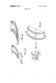
- FIG. 3b is a top view of the passage of the working wheel at the periphery, according to the invention.
- the illustrated turboseparator for polyphase fluids comprises a guide blade assembly 1 (FIG. 1) provided with standard turbine blades 2 (or curved plates); a working wheel 3 with blades 4 and two collecting chambers 5 and 6 located under the working wheel 3 and intended for discharging the heavy phase of the polyphase fluid flow.
- the gap between the blades 2 of the guide blade assembly accommodates acollecting chamber 7 with slots 8 also used for discharging the heavy phase particles.
- the blades 4 of the working wheel 3 have a standard turbine profile 9 (FIG. 212) at the root (section lI-Il) with a small relative blade pitch i.e., the ratio of the distance between adjacent blades to their chord (FIG. 3b). 1
- the blades 4 Near the periphery (section I-l, FIG. 1) the blades 4 have a profile 10 (FIG. 3b) with an increasing chord b for insuring a minimum relative pitch at the periphery.
- Theblades 4 of the working wheel 3 have a variable profile in height, the entrance angle 3 (FIG. 4b) of said profile being always smaller than
- the exit angle a, of the blade 2 of the guide assembly 1 varies from the root g1 (section II--Il, FIG. 2a) of the blade 2 towards its periphery (section I-I) so thatthe exit angle gpf the working fluid flow is smaller at the periphery of the blade 2 of the guide blade assembly-l (section I-l, FIG. 3a) than it is at the root.
- The-decrease of the exit angle a of the working fluid flow from the guide blade assembly intensifies the twisting of the flow and improves the efficiency with which the heavy phase particles of the polyphase fluid are thrown towards the periphery.
- the axial distance 11" (FIG. 1) between the guide assembly 1 and the working wheel 3 is made larger than it is in the known turboseparators.
- the working wheel 3 does not produce actual power and its blades 4 are made in such a way that their periphery has an entrance angle B 90 and functions on compressor duty whereas the root (section IIII) of the blades 4 of the working wheel 3 functions on turbine duty.
- the proposed turboseparator for polyphase fluids can be used as a self-contained unit (for example, in the gas duct at the entry into the installation, and so forth).
- the turbine wheel may be con nected rigidly with the turbine shaft and rotate at the same speed with the latter, producing useful power, though with a lower efiiciency.
- the polyphase working fluid be extracted after the working wheel 3 so as to discharge the heavy phase into the collecting chamber 6. This reduces the quantity of the heavy phase returning into the flow in the flow-through part of the turbine and improves the efficiency of its removal.
- a directing blade assembly be installed before the working wheel 3 of the turboseparator when said wheel is installed in the capacity of a last stage, because said directing blade assembly reduces the twisting of the fluid flow which leaves the working wheel 3.
- turboseparator for polyphase fluids and the turbine incorporating it function as follows:
- the polyphase fluid passes through the guide blade assembly 1, leaves it at an angle a, (FIG. 2a) and is twisted.
- the heavier parts tend to move tangentially to the cylindrical surfaces of the turbine casing.
- the heavy phase particles reach the collecting chamber 7 and are discharged from the flow-through part of the device via the slots 8 together with part of the working fluid.
- the main flow of the working fluid approaches the entrance into the working wheel 3 with already irregularly distributed heavy phase particles along the height of the blade 4.
- all of the coarser particles of the heavy phase are already concentrated on the upper half of the blades 4 of the working wheel 3 while the space near the roots (section ll-II) is occupied by the particles whose absolute velocity C differs but little from the velocity C of the working fluid.
- These particles follow the flow of the working fluid and actually do not comme in contact with the blades 4 of the working wheel 3 sincethe relative velocity W of the particles also difi'ers very little from the relative velocity W of the working fluid.
- the bulk of the heavy phase particles is accumulated at the periphery. Therefore, at the exit from the guide blade assembly 1 the heavy phase particles already lag considerably behind the main flow of the working fluid, i.e., the absolute velocity C of these particles (FIG. 3a) at the periphery is by far lower than the absolute velocity C of the working fluid. Even a wider mismatch of phase velocities is observed in the relative motion (the relative velocity W" at the periphery being much lower than W).
- the particles of the heavy phase contacting the blades 4 of the working wheel 3 are acted upon, apart from the aerodynmaic forces, by Coriolis forces and the forces of friction against the surfaces of the blades 4. it is known that the path of these particles over the surface of the blades 4 of the working wheel 3 is determined in the first place by the direction of Coriolis forces.
- the blades 4 of the working wheel 3 are made in such a manner that Coriolis force is directed towards the entrance edge of the blade 4 because the entrance angle a of the profile 9 of theworking wheel blade 4 is smaller than 90 (FIG. 4b)
- Arrow A in FIGS. 4 and 4b shows the directionof the fluid flow.
- the collecting chambers 5 and 6 are located in such a way that the heavy phase can be thrown directly into these chambers, such a location of the chambers 5 and 6 having no adverse efi'ect on the economy of the installation.
- theproposed device can be supplemented with a number of the known designs improving the removal of the harmful heavy phase, for example, through slots from the blade surface of the guide blade assembly, by making grooves on the entrance edge of these blades, and so forth.
- turboseparator in the turbines of atomic power stations makes it possible to dispose of the remote separators and superheaters thus improving substanphase will also be discharged into the tially the operational characteristics of turbines and the safety of servicing personnel.
- a turboseparator for polyphase fluids comprising: a guide assembly including blades with a profile having an exit angle which diminishes towards the periphery of the blades; a working wheel including blades having a varying profile from the root to the periphery thereof, the latter said profile being of the turbine type at the root thereof and having an exit angle at the periphery not exceeding 90; the distance between the blades of said working wheel and the blades of the guide as-
Landscapes
- Engineering & Computer Science (AREA)
- Mechanical Engineering (AREA)
- General Engineering & Computer Science (AREA)
- Turbine Rotor Nozzle Sealing (AREA)
Abstract
A turboseparator for polyphase media comprising: a guide assembly, a working wheel, and collecting chambers installed near the working wheel periphery. The working wheel blades have a varying profile from the root to the periphery, this profile being of the turbine type near the root. The entrance angle of the profile near the periphery is not over 90*. In a turbine operating with polyphase working fluid, at least one stage is substituted for by the turboseparator.
Description
United States Patent Deich et al.
[15] 3,652,182 [451 Mar. 28, 1972 [54] TURBOSEPARATOR FOR POLYPHASE FLUIDS AND TURBINE INCORPORATING SAID TURBOSEPARATOR [72] Inventors: Mikhail Ellmovich Deich, Energeticheskaya ulitsa, 8 Korpus 1, kv. 56; Gennady Alexeevich Filippov, Molodog' vardeiskaya ulitsa, 24, Korpus 1, kv. 34,
both of Moscow; Sergei Petrovich Sobolev, I
Kharkov, 6 Molchanovsky pereulak, 7, kv. 5, Kharkov; Oleg Alexeevich Povarov, Tashkentskaya ulitsa, l6, Korpus l, kv. 55, Moscow, all of USSR.
[22] Filed: Apr. 1,1970
[21] Appl.No.: 24,769
52 user ..4l5/168,415/199 s1 lnt.Cl.... ..F01d1/00 5s FieldofSearch ..4l5/191,l92,193,199,168,
[56] References Cited UNITED STATES PATENTS- l/1946' Kraft "515/19;
2,378,372 6/1945 Whittle ..4l5/l92 2,660,401 11/1953 Hull ...416/243 1,526,815 2/1925 Warren.... .415/192 1,997,506 4/1935 Adamcikas.... .415/192 2,757,902 8/1956 Slivka et al. ...4l5/l92 1,349,886 8/1920 Junggren ..4l5/l68 FOREIGN PATENTS OR APPLICATIONS 1,201,291 7/1959 France ..4l5/191 588,849 2/1925 France..... ...4l5/199 707,087 4/1931 France ..4l5/l9l Primary Examiner-Henry F. Raduazo Attorney-Waters, Roditi, Schwartz & Nissen [57] ABSTRACT A turboseparator for polyphase media comprising: a guide assembly, a working wheel, and collecting chambers installed near the working wheel periphery. The working wheel blades have a varying profile from the root to the periphery, this profile being of the turbine type near the root. The entrance angle of the profile near the periphery is not over 90. In a turbine operating with polyphase working fluid, at least one stage is substituted for by the turboseparator.
3 Claims, 7 Drawing Figures PMENTmmza 1972 SHEET 2 [IF 3 TURBOSEPARATOR FOR POLYPHASE FLUIDS AND TURBINE INCORPORATING SAID TURBOSEPARATOR The present invention relates to devices for the separation of polyphase media and more specifically to turboseparators of the type which can be utilized in steam and gas turbines operating with a polyphase working liquid and to turboseparators employed for the separation of polyphase fluids in the turbines of atomic power stations.
Known in the art are various kinds of turboseparators for polyphase fluids (see, for example, V.D. Venediktov A study of Operation of a Pyrotative turbine on a Polyphase Flow With Liquid Particles", "Energetica Journal No. 2, 1964, USSR) comprising a guide assembly, a working wheel and collecting chambers installed near the periphery of said wheel.
However, known turboseparators are insufficiently efficient and cannot discharge into collecting chambers even that fraction of the heavy-phase particles from the polyphase flow which is in contact with the moving blades.
It is particularly important to remove the heavy phase from the flow-through section of turbines operating with a polyphase working fluid.
One of the reasons for the low efficiency of known turboseparators, in the first place, is that particles deposited on the surfaces of working wheel blades are acted upon by Coriolis and aerodynamic forces which deflect the paths of the particles towards the exit edge of the blade and reduce the efficiency with which said particles are thrown into the collecting chamber. At the same time, the particles can move in the working wheel passage without coming into contact with the surfaces of the wheel blades. This also reduces the separating capacities of the working wheels.
An object of the invention is to improve the ability of working wheel blades to throw the particles of heavy phases into collecting chambers.
This object is accomplished by providing a turboseparator for polyphase fluids comprising a guide assembly, a working.
wheel and collecting chambers located near the periphery of the working wheel in which, according to the invention, variable-profile blades are provided which have a turbine profile at the root and an entrance angle at the periphery which is not over 90". Moreover, a turbine is provided for working on a polyphase working fluid which has at least one stage substituted for by a turboseparator for polyphase fluids.
It is advantageous that the chord of the working wheel blade be increased from the root to the periphery by a tractor of not more than two.
The exit angle of the blade profile in the guide blade assembly should preferably diminish towards the periphery and the distance between the moving and guide blades can be made equal to not less than one fifth of the height of the guide assembly.
Given below is a detailed description of an embodiment of the invention with reference to the accompanying drawings, in which:
FIG. 1 is a longitudinal section of a turboseparator for polyphase fluids according to the invention;
FIG. 2a diagrammatically illustrates the passage of the guide assembly near the blade roots and the vector field of velocities of various working fluid phases at the exit from said passage, according to the invention;
FIG. 2b diagrammatically illustrates a working wheel passage at the blade root, according to the invention;
FIG. 3a diagrammatically illustrates the passage of the guide blade assembly at the periphery thereof and the vector field of velocities of various working fluid phases at the exit from said passage, according to the invention;
FIG. 3b is a top view of the passage of the working wheel at the periphery, according to the invention; and
FIG. 4a and 4b are schematic representations of the path described by the heavy phase particles over the surface of the working wheel blades (side and top views, respectively), according to the invention.
The illustrated turboseparator for polyphase fluids comprises a guide blade assembly 1 (FIG. 1) provided with standard turbine blades 2 (or curved plates); a working wheel 3 with blades 4 and two collecting chambers 5 and 6 located under the working wheel 3 and intended for discharging the heavy phase of the polyphase fluid flow. The gap between the blades 2 of the guide blade assembly accommodates acollecting chamber 7 with slots 8 also used for discharging the heavy phase particles.
The blades 4 of the working wheel 3 have a standard turbine profile 9 (FIG. 212) at the root (section lI-Il) with a small relative blade pitch i.e., the ratio of the distance between adjacent blades to their chord (FIG. 3b). 1
Near the periphery (section I-l, FIG. 1) the blades 4 have a profile 10 (FIG. 3b) with an increasing chord b for insuring a minimum relative pitch at the periphery.
The-decrease of the exit angle a of the working fluid flow from the guide blade assembly intensifies the twisting of the flow and improves the efficiency with which the heavy phase particles of the polyphase fluid are thrown towards the periphery.
The axial distance 11" (FIG. 1) between the guide assembly 1 and the working wheel 3 is made larger than it is in the known turboseparators.
This allows a larger quantity of heavy phase particles to be thrown towards the periphery and makes it possible to install the collecting chamber 7 with the slots 8.
It is known that a decrease of the peripheral speeds of the working wheel blades 4 improves the separation of the heavy phase into the collecting chambers 5 and 6 for which purpose it is advantageous that the working wheel 3 be installed on bearings 11 (FIG. I).
In the case, the working wheel 3 does not produce actual power and its blades 4 are made in such a way that their periphery has an entrance angle B 90 and functions on compressor duty whereas the root (section IIII) of the blades 4 of the working wheel 3 functions on turbine duty.
The ratio of powers on the peripheral and root sections of the blades 4 of the working wheel 3 allows in each particular case obtaining any pre-set rmp of the working wheel 3 and the maximum effect of heavy phase separation.
The proposed turboseparator for polyphase fluids can be used as a self-contained unit (for example, in the gas duct at the entry into the installation, and so forth).
A number of such devices mounted in tandem form a multistage turboseparator for polyphase fluids.
In such a layout the subsequent stages will be still more efficient since, at the entrance into the guide assembly, the fluid will already have a higher concentration of heavy phases at the periphery.
In view of the above said, it is highly efficient to use the proposed device in multistage turbines operating with a polyphase working fluid in the capacity of one or more turbine stages. In such an arrangement, the turbine wheel may be con nected rigidly with the turbine shaft and rotate at the same speed with the latter, producing useful power, though with a lower efiiciency.
However, the maximum effect in separating the phases of the polyphase fluid flow will be achieved at low peripheral speeds (under 150 m/s). Therefore, it is working wheel 2 be mounted on bearings 11.
The use of such a turboseparator in the capacity of an intermediate turbine stage will make it possible to separate the heavy phase of a polyphase working fluid, because said heavy phase destroys the flow-through part of the turbine and reduces its efficiency.
This insures reliable and economical operation of the subsequent stages.
At the point of installation of the proposed turboseparator in the turbine, it is advantageous that the polyphase working fluid be extracted after the working wheel 3 so as to discharge the heavy phase into the collecting chamber 6. This reduces the quantity of the heavy phase returning into the flow in the flow-through part of the turbine and improves the efficiency of its removal.
The removal of the heavy phase together with the part of the working fluid is equally justified for the collecting chambers 5 and 7 though in this case it is not expedient to extract more than 1-2 percent of the working fluid.
The use of the proposed turboseparator in the capacity of an intermediate turbine stage in a multistage, turbine will, naturally, cause a considerable distortion of the vector field of velocities of the working fluid flow alongthe height of the blade at the entrance into the next turbine stage.
Therefore, if losses are to be diminished, the guide assembly 1 of the next stage should be made to conform to this distortion.
' The use of the proposed turboseparatorin the capacity of the subsequent stage in a multicylinder turbine also yields effective results.
By installing'such a turboseparator as the last stagein the first'cylinder, it is possible to remove the heavy phase and thus to dispense with a bulky and costly remote installed separator.
in this case, losses are by far'smaller than they are-in the steam or gas duct and in the remote separator proper.
To enhance turbine economy, it is also advantageous that a directing blade assembly be installed before the working wheel 3 of the turboseparator when said wheel is installed in the capacity of a last stage, because said directing blade assembly reduces the twisting of the fluid flow which leaves the working wheel 3.
The turboseparator for polyphase fluids and the turbine incorporating it function as follows:
The polyphase fluid passes through the guide blade assembly 1, leaves it at an angle a, (FIG. 2a) and is twisted. The heavier parts tend to move tangentially to the cylindrical surfaces of the turbine casing.
As a result, the bulk of the heavy phase moves towards the periphery (section 1-1).
The longer the axial distance between the guide blade assembly l and the working wheel 3, the larger is the amount of such particles which will accumulate at the periphery.
The heavy phase particles reach the collecting chamber 7 and are discharged from the flow-through part of the device via the slots 8 together with part of the working fluid.
The main flow of the working fluid approaches the entrance into the working wheel 3 with already irregularly distributed heavy phase particles along the height of the blade 4. Actually, all of the coarser particles of the heavy phase are already concentrated on the upper half of the blades 4 of the working wheel 3 while the space near the roots (section ll-II) is occupied by the particles whose absolute velocity C differs but little from the velocity C of the working fluid. These particles follow the flow of the working fluid and actually do not comme in contact with the blades 4 of the working wheel 3 sincethe relative velocity W of the particles also difi'ers very little from the relative velocity W of the working fluid.
This is the reason why the blades 4 of the proposed turboseparator have at the roots a turbine profile 9 (H6. 2b) working under optimum conditions.
advantageous that the At the same time, the bulk of the heavy phase particles is accumulated at the periphery. Therefore, at the exit from the guide blade assembly 1 the heavy phase particles already lag considerably behind the main flow of the working fluid, i.e., the absolute velocity C of these particles (FIG. 3a) at the periphery is by far lower than the absolute velocity C of the working fluid. Even a wider mismatch of phase velocities is observed in the relative motion (the relative velocity W" at the periphery being much lower than W).
The particles of the heavy phase contacting the blades 4 of the working wheel 3 are acted upon, apart from the aerodynmaic forces, by Coriolis forces and the forces of friction against the surfaces of the blades 4. it is known that the path of these particles over the surface of the blades 4 of the working wheel 3 is determined in the first place by the direction of Coriolis forces.
The aerodynamic forces divert the path of the heavy phase to the exit edge and, if the component of Coriolis force (at the entrance angle a 90) also acts in this direction, the heavy phase will again be thrown into the flow of the working fluid and may fail to reach the collecting chambers 5 and 6.
In the proposed turboseparator for polyphase fluids and'in the. turbine incorporating it, the blades 4 of the working wheel 3 are made in such a manner that Coriolis force is directed towards the entrance edge of the blade 4 because the entrance angle a of the profile 9 of theworking wheel blade 4 is smaller than 90 (FIG. 4b)
Bearing in mind that the effect of Coriolis force is actually always higher than that of the aerodynamic force, the heavy phase of the fluid flow, contacting the blades 4 of the working wheel 3 will stay on the surface of the blades- 4 and move towards the periphery (section [-1) against the working fluid flow (FIG. 4).
Arrow A in FIGS. 4 and 4b shows the directionof the fluid flow.
Thus, the probability of the particles in contact with the blades 4 being thrown into the collecting chambers 5 and 6 is increased considerably.
The particles deflected from the entrance edges of the blades 4 and the heavy phase particles thrown forward against the flow by Coriolis forces and returned by the working fluid flow will again come into contact with the blades 4 of the working wheel 3 though at a larger height.
The probability the coming of these particles onto the blades 4 of the working wheel 3 rises with the reduction in the pitch of the blades 4.
As a result, the heavy collecting chamber 5.
To raise the efficiency of removing the heavy phase particles, the collecting chambers 5 and 6 (FIG. 1) are located in such a way that the heavy phase can be thrown directly into these chambers, such a location of the chambers 5 and 6 having no adverse efi'ect on the economy of the installation.
Making the entrance angle a of the profile of the working wheel blade 4 smaller than it is possible to direct the heavy phase particles contacting the surface of said blades 4 towards the periphery and against the flow of the working fluid.
lntensive'discharge of the heavy phase after the guide assembly into the collecting chamber 7 and improved trapping of the heavy phase particles above the blades 4 of the working wheel 3 by the collecting chambers 5 and 6 in combination with the suction and extraction of a part of the working fluid contribute to solving the urgent and vital engineering problem of separating the polyphase media.
Naturally, theproposed device can be supplemented with a number of the known designs improving the removal of the harmful heavy phase, for example, through slots from the blade surface of the guide blade assembly, by making grooves on the entrance edge of these blades, and so forth.
The use of the proposed turboseparator in the turbines of atomic power stations makes it possible to dispose of the remote separators and superheaters thus improving substanphase will also be discharged into the tially the operational characteristics of turbines and the safety of servicing personnel.
We claim:
1. A turboseparator for polyphase fluids comprising: a guide assembly including blades with a profile having an exit angle which diminishes towards the periphery of the blades; a working wheel including blades having a varying profile from the root to the periphery thereof, the latter said profile being of the turbine type at the root thereof and having an exit angle at the periphery not exceeding 90; the distance between the blades of said working wheel and the blades of the guide as-
Claims (3)
1. A turboseparator for polyphase fluids comprising: a guide assembly including blades with a profile having an exit angle which diminishes towards the periphery of the blades; a working wheel including blades having a varying profile from the root to the periphery thereof, the latter said profile being of the turbine type at the root thereof and having an exit angle at the periphery not exceeding 90* ; the distance between the blades of said working wheel and the blades of the guide assembly being not less than one fifth of the height of said guide assembly, and means providing a collecting chamber peripherally disposed with respect to the blades of the working wheel.
2. A turboseparator according to claim 1 wherein the blades of said working wheel have a chord which increases from the root to the periphery by a factor of not more than two.
3. A turbine operable with a polyphase working fluid comprising a plurality of cooperative stages of which at least one stage consists of the turboseparator claimed in claim 1.
Applications Claiming Priority (1)
| Application Number | Priority Date | Filing Date | Title |
|---|---|---|---|
| US2476970A | 1970-04-01 | 1970-04-01 |
Publications (1)
| Publication Number | Publication Date |
|---|---|
| US3652182A true US3652182A (en) | 1972-03-28 |
Family
ID=21822308
Family Applications (1)
| Application Number | Title | Priority Date | Filing Date |
|---|---|---|---|
| US24769A Expired - Lifetime US3652182A (en) | 1970-04-01 | 1970-04-01 | Turboseparator for polyphase fluids and turbine incorporating said turboseparator |
Country Status (1)
| Country | Link |
|---|---|
| US (1) | US3652182A (en) |
Cited By (8)
| Publication number | Priority date | Publication date | Assignee | Title |
|---|---|---|---|---|
| US4123196A (en) * | 1976-11-01 | 1978-10-31 | General Electric Company | Supersonic compressor with off-design performance improvement |
| FR2397519A1 (en) * | 1977-07-15 | 1979-02-09 | Mitsui Shipbuilding Eng | AXIAL TURBINE |
| US6375419B1 (en) * | 1995-06-02 | 2002-04-23 | United Technologies Corporation | Flow directing element for a turbine engine |
| US6413044B1 (en) * | 2000-06-30 | 2002-07-02 | Alstom Power N.V. | Blade cooling in gas turbine |
| US20050013693A1 (en) * | 2001-01-12 | 2005-01-20 | Mitsubishi Heavy Industries Ltd. | Blade structure in a gas turbine |
| JP2012241607A (en) * | 2011-05-19 | 2012-12-10 | Toshiba Corp | Steam turbine |
| US20170204728A1 (en) * | 2014-06-26 | 2017-07-20 | Mitsubishi Heavy Industries, Ltd. | Turbine rotor blade row, turbine stage, and axial-flow turbine |
| US20180030835A1 (en) * | 2015-02-10 | 2018-02-01 | Mitsubishi Hitachi Power Systems, Ltd. | Turbine and gas turbine |
Citations (10)
| Publication number | Priority date | Publication date | Assignee | Title |
|---|---|---|---|---|
| US1349886A (en) * | 1919-05-09 | 1920-08-17 | Gen Electric | Elastic-fluid turbine |
| US1526815A (en) * | 1923-12-22 | 1925-02-17 | Gen Electric | Elastic-fluid turbine |
| FR588849A (en) * | 1923-11-27 | 1925-05-15 | Vickers Electrical Co Ltd | Improvements to elastic fluid turbines |
| FR707087A (en) * | 1930-03-06 | 1931-07-02 | Rateau Sa | Device for increasing efficiency in turbine blades |
| US1997506A (en) * | 1930-09-29 | 1935-04-09 | Adamcikas Mykas | Guide vane for rotary machines |
| US2378372A (en) * | 1937-12-15 | 1945-06-12 | Whittle Frank | Turbine and compressor |
| US2392673A (en) * | 1943-08-27 | 1946-01-08 | Gen Electric | Elastic fluid turbine |
| US2660401A (en) * | 1951-08-07 | 1953-11-24 | Gen Electric | Turbine bucket |
| US2757902A (en) * | 1952-05-22 | 1956-08-07 | William R Slivka | Non-twisted rotor blade turbine |
| FR1201291A (en) * | 1957-09-12 | 1959-12-29 | Bbc Brown Boveri & Cie | Blades for axial flow turbines |
-
1970
- 1970-04-01 US US24769A patent/US3652182A/en not_active Expired - Lifetime
Patent Citations (10)
| Publication number | Priority date | Publication date | Assignee | Title |
|---|---|---|---|---|
| US1349886A (en) * | 1919-05-09 | 1920-08-17 | Gen Electric | Elastic-fluid turbine |
| FR588849A (en) * | 1923-11-27 | 1925-05-15 | Vickers Electrical Co Ltd | Improvements to elastic fluid turbines |
| US1526815A (en) * | 1923-12-22 | 1925-02-17 | Gen Electric | Elastic-fluid turbine |
| FR707087A (en) * | 1930-03-06 | 1931-07-02 | Rateau Sa | Device for increasing efficiency in turbine blades |
| US1997506A (en) * | 1930-09-29 | 1935-04-09 | Adamcikas Mykas | Guide vane for rotary machines |
| US2378372A (en) * | 1937-12-15 | 1945-06-12 | Whittle Frank | Turbine and compressor |
| US2392673A (en) * | 1943-08-27 | 1946-01-08 | Gen Electric | Elastic fluid turbine |
| US2660401A (en) * | 1951-08-07 | 1953-11-24 | Gen Electric | Turbine bucket |
| US2757902A (en) * | 1952-05-22 | 1956-08-07 | William R Slivka | Non-twisted rotor blade turbine |
| FR1201291A (en) * | 1957-09-12 | 1959-12-29 | Bbc Brown Boveri & Cie | Blades for axial flow turbines |
Cited By (12)
| Publication number | Priority date | Publication date | Assignee | Title |
|---|---|---|---|---|
| US4123196A (en) * | 1976-11-01 | 1978-10-31 | General Electric Company | Supersonic compressor with off-design performance improvement |
| FR2397519A1 (en) * | 1977-07-15 | 1979-02-09 | Mitsui Shipbuilding Eng | AXIAL TURBINE |
| US6375419B1 (en) * | 1995-06-02 | 2002-04-23 | United Technologies Corporation | Flow directing element for a turbine engine |
| US6413044B1 (en) * | 2000-06-30 | 2002-07-02 | Alstom Power N.V. | Blade cooling in gas turbine |
| US20050013693A1 (en) * | 2001-01-12 | 2005-01-20 | Mitsubishi Heavy Industries Ltd. | Blade structure in a gas turbine |
| US20050089403A1 (en) * | 2001-01-12 | 2005-04-28 | Mitsubishi Heavy Industries Ltd. | Blade structure in a gas turbine |
| US7229248B2 (en) | 2001-01-12 | 2007-06-12 | Mitsubishi Heavy Industries, Ltd. | Blade structure in a gas turbine |
| JP2012241607A (en) * | 2011-05-19 | 2012-12-10 | Toshiba Corp | Steam turbine |
| US20170204728A1 (en) * | 2014-06-26 | 2017-07-20 | Mitsubishi Heavy Industries, Ltd. | Turbine rotor blade row, turbine stage, and axial-flow turbine |
| US11220909B2 (en) * | 2014-06-26 | 2022-01-11 | Mitsubishi Heavy Industries, Ltd. | Turbine rotor blade row, turbine stage, and axial-flow turbine |
| US20180030835A1 (en) * | 2015-02-10 | 2018-02-01 | Mitsubishi Hitachi Power Systems, Ltd. | Turbine and gas turbine |
| US10655471B2 (en) * | 2015-02-10 | 2020-05-19 | Mitsubishi Hitachi Power Systems, Ltd. | Turbine and gas turbine |
Similar Documents
| Publication | Publication Date | Title |
|---|---|---|
| US2314572A (en) | Turboengine | |
| US5984628A (en) | Steam turbine | |
| US3652182A (en) | Turboseparator for polyphase fluids and turbine incorporating said turboseparator | |
| EP0032815A2 (en) | Two-phase reaction turbine | |
| GB2287288A (en) | Pump suitable for a multiphase fluid | |
| RU2614309C2 (en) | Wet gas compressor and method | |
| US4738585A (en) | High-speed water separator | |
| US3415383A (en) | Centrifugal separator | |
| US3881842A (en) | Diaphragm for steam turbine stage | |
| CA2927037C (en) | Rotor assembly with scoop | |
| CA2927035C (en) | Rotor assembly with wear member | |
| US2798658A (en) | Volume controls for centrifugal fans | |
| US3120374A (en) | Exhaust scroll for turbomachine | |
| US2640678A (en) | Fluid translating device | |
| EP0446900A1 (en) | Mixed-flow compressor | |
| US3318077A (en) | Device for removing water from the stages of steam turbines | |
| Deich et al. | Improvements in and relating to apparatus for separating polyphase media | |
| DE102010064450B3 (en) | Relaxation turbine for the relaxation of gas | |
| RU2028464C1 (en) | Separator stage | |
| EP2650492B1 (en) | Steam turbine, power plant, and operation method for steam turbine | |
| US2914296A (en) | Overspeed control for fuel system turbopump | |
| US1834452A (en) | Means for draining the low pressure blading of steam turbines | |
| EP0097605A2 (en) | High speed supersonic impulse turbine | |
| US2596647A (en) | Outlet guiding arrangement | |
| US3525213A (en) | Gas turbine engine with aerodynamic torque converter drive |