EP1659293A2 - Turbomachine - Google Patents
Turbomachine Download PDFInfo
- Publication number
- EP1659293A2 EP1659293A2 EP05025062A EP05025062A EP1659293A2 EP 1659293 A2 EP1659293 A2 EP 1659293A2 EP 05025062 A EP05025062 A EP 05025062A EP 05025062 A EP05025062 A EP 05025062A EP 1659293 A2 EP1659293 A2 EP 1659293A2
- Authority
- EP
- European Patent Office
- Prior art keywords
- blade
- openings
- hub
- dav
- sko
- Prior art date
- Legal status (The legal status is an assumption and is not a legal conclusion. Google has not performed a legal analysis and makes no representation as to the accuracy of the status listed.)
- Granted
Links
Images


Classifications
-
- F—MECHANICAL ENGINEERING; LIGHTING; HEATING; WEAPONS; BLASTING
- F04—POSITIVE - DISPLACEMENT MACHINES FOR LIQUIDS; PUMPS FOR LIQUIDS OR ELASTIC FLUIDS
- F04D—NON-POSITIVE-DISPLACEMENT PUMPS
- F04D29/00—Details, component parts, or accessories
- F04D29/40—Casings; Connections of working fluid
- F04D29/52—Casings; Connections of working fluid for axial pumps
- F04D29/522—Casings; Connections of working fluid for axial pumps especially adapted for elastic fluid pumps
- F04D29/526—Details of the casing section radially opposing blade tips
-
- F—MECHANICAL ENGINEERING; LIGHTING; HEATING; WEAPONS; BLASTING
- F01—MACHINES OR ENGINES IN GENERAL; ENGINE PLANTS IN GENERAL; STEAM ENGINES
- F01D—NON-POSITIVE DISPLACEMENT MACHINES OR ENGINES, e.g. STEAM TURBINES
- F01D11/00—Preventing or minimising internal leakage of working-fluid, e.g. between stages
- F01D11/08—Preventing or minimising internal leakage of working-fluid, e.g. between stages for sealing space between rotor blade tips and stator
- F01D11/10—Preventing or minimising internal leakage of working-fluid, e.g. between stages for sealing space between rotor blade tips and stator using sealing fluid, e.g. steam
-
- F—MECHANICAL ENGINEERING; LIGHTING; HEATING; WEAPONS; BLASTING
- F01—MACHINES OR ENGINES IN GENERAL; ENGINE PLANTS IN GENERAL; STEAM ENGINES
- F01D—NON-POSITIVE DISPLACEMENT MACHINES OR ENGINES, e.g. STEAM TURBINES
- F01D5/00—Blades; Blade-carrying members; Heating, heat-insulating, cooling or antivibration means on the blades or the members
- F01D5/12—Blades
- F01D5/14—Form or construction
- F01D5/141—Shape, i.e. outer, aerodynamic form
- F01D5/145—Means for influencing boundary layers or secondary circulations
-
- F—MECHANICAL ENGINEERING; LIGHTING; HEATING; WEAPONS; BLASTING
- F04—POSITIVE - DISPLACEMENT MACHINES FOR LIQUIDS; PUMPS FOR LIQUIDS OR ELASTIC FLUIDS
- F04D—NON-POSITIVE-DISPLACEMENT PUMPS
- F04D29/00—Details, component parts, or accessories
- F04D29/66—Combating cavitation, whirls, noise, vibration or the like; Balancing
- F04D29/68—Combating cavitation, whirls, noise, vibration or the like; Balancing by influencing boundary layers
- F04D29/681—Combating cavitation, whirls, noise, vibration or the like; Balancing by influencing boundary layers especially adapted for elastic fluid pumps
- F04D29/682—Combating cavitation, whirls, noise, vibration or the like; Balancing by influencing boundary layers especially adapted for elastic fluid pumps by fluid extraction
-
- F—MECHANICAL ENGINEERING; LIGHTING; HEATING; WEAPONS; BLASTING
- F04—POSITIVE - DISPLACEMENT MACHINES FOR LIQUIDS; PUMPS FOR LIQUIDS OR ELASTIC FLUIDS
- F04D—NON-POSITIVE-DISPLACEMENT PUMPS
- F04D29/00—Details, component parts, or accessories
- F04D29/66—Combating cavitation, whirls, noise, vibration or the like; Balancing
- F04D29/68—Combating cavitation, whirls, noise, vibration or the like; Balancing by influencing boundary layers
- F04D29/681—Combating cavitation, whirls, noise, vibration or the like; Balancing by influencing boundary layers especially adapted for elastic fluid pumps
- F04D29/684—Combating cavitation, whirls, noise, vibration or the like; Balancing by influencing boundary layers especially adapted for elastic fluid pumps by fluid injection
-
- F—MECHANICAL ENGINEERING; LIGHTING; HEATING; WEAPONS; BLASTING
- F04—POSITIVE - DISPLACEMENT MACHINES FOR LIQUIDS; PUMPS FOR LIQUIDS OR ELASTIC FLUIDS
- F04D—NON-POSITIVE-DISPLACEMENT PUMPS
- F04D29/00—Details, component parts, or accessories
- F04D29/66—Combating cavitation, whirls, noise, vibration or the like; Balancing
- F04D29/68—Combating cavitation, whirls, noise, vibration or the like; Balancing by influencing boundary layers
- F04D29/681—Combating cavitation, whirls, noise, vibration or the like; Balancing by influencing boundary layers especially adapted for elastic fluid pumps
- F04D29/685—Inducing localised fluid recirculation in the stator-rotor interface
-
- F—MECHANICAL ENGINEERING; LIGHTING; HEATING; WEAPONS; BLASTING
- F04—POSITIVE - DISPLACEMENT MACHINES FOR LIQUIDS; PUMPS FOR LIQUIDS OR ELASTIC FLUIDS
- F04D—NON-POSITIVE-DISPLACEMENT PUMPS
- F04D27/00—Control, e.g. regulation, of pumps, pumping installations or pumping systems specially adapted for elastic fluids
- F04D27/02—Surge control
- F04D27/0207—Surge control by bleeding, bypassing or recycling fluids
- F04D27/023—Details or means for fluid extraction
-
- F—MECHANICAL ENGINEERING; LIGHTING; HEATING; WEAPONS; BLASTING
- F04—POSITIVE - DISPLACEMENT MACHINES FOR LIQUIDS; PUMPS FOR LIQUIDS OR ELASTIC FLUIDS
- F04D—NON-POSITIVE-DISPLACEMENT PUMPS
- F04D27/00—Control, e.g. regulation, of pumps, pumping installations or pumping systems specially adapted for elastic fluids
- F04D27/02—Surge control
- F04D27/0207—Surge control by bleeding, bypassing or recycling fluids
- F04D27/0238—Details or means for fluid reinjection
-
- Y—GENERAL TAGGING OF NEW TECHNOLOGICAL DEVELOPMENTS; GENERAL TAGGING OF CROSS-SECTIONAL TECHNOLOGIES SPANNING OVER SEVERAL SECTIONS OF THE IPC; TECHNICAL SUBJECTS COVERED BY FORMER USPC CROSS-REFERENCE ART COLLECTIONS [XRACs] AND DIGESTS
- Y02—TECHNOLOGIES OR APPLICATIONS FOR MITIGATION OR ADAPTATION AGAINST CLIMATE CHANGE
- Y02T—CLIMATE CHANGE MITIGATION TECHNOLOGIES RELATED TO TRANSPORTATION
- Y02T50/00—Aeronautics or air transport
- Y02T50/60—Efficient propulsion technologies, e.g. for aircraft
Definitions
- the invention relates to fluid flow machines such as fans, compressors, pumps and fans, both axial, semi-axial and radial.
- the working medium or fluid may be gaseous or liquid.
- the turbomachine according to the invention may comprise one or more stages, usually each with a rotor and a stator; in some cases, the stage is formed only by a rotor.
- the invention relates to a fluid power machine having at least one rotor, the rotor comprising a plurality of rotor blades secured to a rotating shaft. At least one stator may exist, the stator being provided with stationary stator blades. There is a housing which limits the flow of the rotor and the stator with a fluid to the outside.
- the present invention has for its object to provide a fluid flow machine of the type mentioned, which, while avoiding the prior art, a very effective boundary layer control by a dynamic secondary fluid guide, i. a pulsating fluid removal or fluid supply or a temporally changing occurring fluid removal and supply having.
- the rotor consists of a number of blades, which are connected to the rotating shaft of the fluid flow machine and deliver energy to the working fluid.
- a stator consists of a number of stationary blades, which can be designed on the hub side as the housing side with a fixed or free blade end. At least one rotor or stator of the fluid power machine has a free blade end with an adjacent nip.
- the turbomachine may include a stator in front of the first rotor, a so-called leading wheel. Also, at least one stator or Vorleitrad be deviating from the immovable fixation rotatably mounted to change the angle of attack. An adjustment is made for example by a spindle accessible from outside the annular channel.
- the turbomachine may have at least one row of adjustable rotors.
- the fluid flow machine has two counter-rotating waves at Mehrstuftechnik, so that the rotor blade rows change the direction of rotation from stage to stage. There are no stators between successive rotors.
- the turbomachine may also have a bypass configuration such that the single-flow annulus behind a given row of blades divides into two concentric annuli, each of which includes at least one more row of blades.
- a fluid power machine having means for time varying and possibly directional alternating fluid movement between raceway adjacent hub and housing surfaces (LNGO) and blade channel defining surfaces (SKO), with openings or aperture groups distributed along the circumference of LNGO at least one blade row whose centroids are one or more times the blade pitch at the free end of the relevant row of blades from each other and thus form a dynamically operating supply point (DAV).
- DAV dynamically operating supply point
- the openings in LNGO via at least one arranged outside the main flow path chamber and / or conduit with further openings on SKO the same blade row and / or openings at SKO at least one blade of at least one other adjacent row of blades in conjunction.
- fluid is taken from the flow path in the region of the running gap-adjacent hub and housing surface (LNGO).
- the removal takes place at a dynamically operating supply center (DAV).
- the fluid is passed via a conduit and optionally via a chamber, which is interposed in the conduit, wherein the forwarding can take place either against the main flow direction or in the main flow direction.
- the discharge of the fluid takes place on the blade channel limiting surfaces (SKO), wherein the fluid is discharged either through the housing wall or over a surface of a rotor or stator.
- SKO blade channel limiting surfaces
- the possibility of alternately moving the fluid in the line in the opposite direction is created by the oscillating movement of the fluid in the line, so that both of the above-described openings SKO and DAV serve both for the introduction and the removal of fluid.
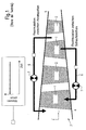
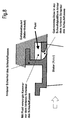
- Fig. 1 shows a highly simplified representation solutions according to the prior art. Shown is a turbomachine having a number of rows of blades, rotors 1 such as stators 2, within the main flow path defined by the annular channel 3, usually a hub 4 (rotor drum) and a housing 5.
- rotors 1 such as stators 2
- the annular channel 3 usually a hub 4 (rotor drum) and a housing 5.
- Existing fluid circulation systems 6 possibly with throttle element 7) achieve an influence on the flow with secondary fluid flows, which remain unchanged in time at a fixed operating point of the turbomachine. This is indicated by a small rectangle symbol in the secondary flow paths and shown graphically in the upper part of the picture.
- the openings for the exchange of the secondary fluid are arranged in known solutions either at locations which are exposed to a constant operating pressure at a given operating point, or are such that pressure fluctuations, as for example at the radial running gap of a rotor without shroud at a certain non-rotating Location of the housing 5 or at the radial gap of a stator without shroud occur at a certain rotating location of the hub 4, not be used for a time-varying secondary fluid transfer. Consequently, those are spent Secondary fluid mass flows unfavorably large, constant in time and directional.
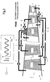
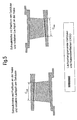
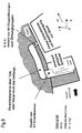
- FIG. 2 shows in greatly simplified representation the flow machine according to the invention, with a number of rows of blades (rotors 1 such as stators 2), within the main flow path 3 (annular channel) through the annular channel 3, usually a hub (rotor drum) and a housing fifth , is limited.
- a supply point for a pressure which varies greatly over time with the blade sequence frequency of the relevant blade row is created by means of specially arranged openings at hub-and-housing surfaces (LNGO) adjoining gap.
- LNGO hub-and-housing surfaces
- This dynamically operating supply point (DAV), which is always provided at the radial gap of the free blade ends, is connected, optionally via a fixed or regulated throttle element, via a line system with openings on the blade channel limiting surfaces (SKO) of one or more blade rows of the fluid flow machine.
- DAV dynamically operating supply point
- the resulting secondary fluid mass flows are small, time varying, and possibly directional alternating. This is indicated by a small rectangle symbol in the secondary flow paths and shown graphically in the upper part of the picture.
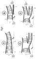
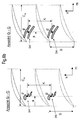
- FIG. 3 shows four possible main flow path configurations of the dynamic self-flow turbomachine of the present invention. Shown is a respective flowed through from left to right annular channel. A rotor drum turns around the marked machine axis. at the embodiments shown in Fig. 3B and 3D, a further rotor drum (hub) is provided. The rotors 1, stators 2 and the Vorleitrad 9 are each labeled, it is shown in a schematic manner, a blade.
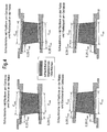
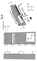
- FIG. 4 shows the definitions of the term of the blade channel limiting surfaces SKO used according to the invention. It is, as can be seen from the caption of Fig. 4, a different arrangement and dimensioning of the individual areas provided. Again, it is simplified to show a row of blades disposed within the main flow path (annular channel 3) between a housing 5 and a hub 4 (rotor drum). Blade channel limiting surfaces according to the present invention are, as shown in Fig.
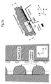
- FIG. 5 shows the definitions of the term of the running gap-adjacent hub and housing surfaces LNGO used according to the invention. Again, it is shown in simplified form a row of blades arranged within a main flow path (annular channel) between a housing 5 and a hub 4 (rotor drum).
- Laufspaltangrenzende hub and housing surfaces in the context of the present invention as shown in Fig. 5, all surfaces of the inner and outer boundary of the Main flow path (ring channel) of the fluid flow machine, which adjoin the radial gap of a rotor or stator row in the region of the available between front and rear edge position, meridional Schaufelsehendorf (CmG or CmN), and characterized in that between them and the Blades of the relevant blade row is a relative movement.
- Fig. 6a shows the dynamically operating supply point DAV, which represents the basis of all solutions according to the invention. By definition, it is formed on running gap-adjacent surfaces of the hub 4 or the housing 5.
- the left part of the figure shows a corresponding configuration in the plane given by the radial direction r and the axial direction x.
- the running gap is formed between the blade tips of the relevant blade row and the relevant wall. There is a relative movement between the blade tips and the wall.
- the centroids of the individual openings or of the individual opening groups have a distance a from the leading edge which can amount to between 0% and 100% of the meridional leaf tip chord length Cm (0 ⁇ a ⁇ Cm).
- 0.05 * Cm ⁇ a ⁇ 0.40 * Cm make the connection to a separate from the main flow path arrangement of flow channels extending over parts or the entirety of the circumference and connects to SKO upstream or downstream rows of blades.
- FIG. 6b shows alternative arrangements according to the invention in which an opening group occurs at the location of an individual opening, characterized in that each group as such can be unambiguously identified on the basis of the size of the intermediate spaces, has a group-related area centroid F and coincides with one another within a vane passage without overlap Suction or pressure side of two juxtaposed blades can be positioned.
- the shape of the group belonging to the openings is of minor importance and therefore freely selectable. According to the invention, specially shaped holes or slots are possible.
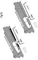
- FIG. 7a shows a solution according to the invention with connection between DAV and a location of the main flow path in front of the same blade row (basic concept A).
- a number of N1 openings establish a connection to an intermediate chamber located outside the main flow path, which may extend over all or part of the periphery.
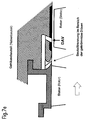
- FIG. 7b shows a particularly simple structural design of the basic concept A.
- the openings of the DAV are designed here as individual drill holes whose axis can be inclined both in the meridian and in the circumferential direction.
- an intermediate chamber is provided which extends along the entire circumference. Upstream of the DAV, the intermediate chamber adjoins openings which are likewise arranged on the main flow path and, in a particularly advantageous embodiment according to the invention, have the shape of a downstream-curved nozzle.
- the curved nozzle is characterized in that the perpendicular of its narrow cross-sectional area encloses an acute angle with the meridian direction.
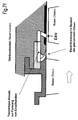
- FIG. 7 c shows the same configuration, but with additional separating bodies for forming individual channels, each leading to a nozzle.
- the cross-section of the intermediate chamber and the connecting channels in the meridian plane can have additional curves, unlike the simple rectangular shape selected here, and the delimiting walls do not have to be arranged parallel or perpendicular to the main flow path.
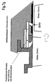
- the openings of the DAV can either, as shown in Figure 7b, c lead by the applied to the wall member on the hub or on the housing squinger, or as shown in Figure 7d, be formed in an embedded in the squish covering projection of the wall member, which is flush with the surface of the Ansteifbelages or radially retracted relative to the squeal.
- the wall material projection is provided at discrete locations or the entire circumference.
- the openings of the DAV can also be formed in a wall provided without any squealer coating.
- FIG. 7e further shows a constructive solution according to the invention for the basic concept A, in which components of the upstream blade row are included.
- This may be an assembly of housing and stator parts (running gap on the rotor) or alternatively an assembly of hub and rotor parts (running gap on the stator 2).
- the openings located upstream of the DAV here again shown as curved nozzles, are formed jointly by housing and stator components (or hub and rotor components).
- the boundary between the components concerned is located anywhere on the nozzle contour.
- Figure 7f shows a related configuration, but with an additional, ideally semi-annular, or annular insert overlapping the nozzle area and having individual channels (separator) matched to the number of nozzles and nozzle shape.
- FIG. 7g furthermore shows a design solution according to the invention for the basic concept A, in which components of the upstream blade row are included.
- the openings located upstream of the DAV again shown here as curved nozzles, are in this variant completely arranged in components of the upstream row of blades and are located at least partially within a passage between two blades.
- This arrangement can also be designed according to the invention with Trenn emotions whatsoever (as Figure 7g shows) or in a simpler manner without Trennmaschinenic.
- FIG. 8 shows the concept of a blade component with circumferential feet and at least one curved nozzle arranged at least partially within the bladed space (blade passage). Characteristic for this purpose is the arrangement of the nozzle downstream of the rear leg of the blade root.
- FIG. 9 shows a solution according to the invention with connection between DAV and SKO of an upstream blade row (basic concept B).
- the bucket suction side has been chosen as SKO.
- a configuration of holes is shown as openings.
- a number of N1 orifices of the DAV connect to an intermediate chamber located outside the main flowpath, which can extend over all or part of the circumference.
- a number of N2> 1 channels establish the connection between the intermediate chamber and the inside of the blade of the upstream blade row. At least one blade of the row is made accessible via one channel each.
- FIG. 10 shows a solution according to the invention with connection between DAV and SKO of a row of blades located in the adjacent main flow path (basic concept C).
- the bucket suction side has been chosen as SKO.
- a configuration of holes is shown as openings.
- a number of N1 openings or groups of openings of the DAV establish a connection to an intermediate chamber located outside the main flow paths 1 and 2, which extend over all or part of the circumference can.
- a number of N2> 1 channels establish the connection between the intermediate chamber and the inside of the blade of the upstream blade row. At least one blade of the series in the main flow path 2 is made accessible via one channel each.
Landscapes
- Engineering & Computer Science (AREA)
- Mechanical Engineering (AREA)
- General Engineering & Computer Science (AREA)
- Physics & Mathematics (AREA)
- Fluid Mechanics (AREA)
- Structures Of Non-Positive Displacement Pumps (AREA)
Abstract
Description
Die Erfindung bezieht sich auf Strömungsarbeitsmaschinen wie etwa Bläser, Verdichter, Pumpen und Ventilatoren, sowohl in axialer, halbaxialer als auch in radialer Bauart. Das Arbeitsmedium oder Fluid kann gasförmig oder flüssig sein.The invention relates to fluid flow machines such as fans, compressors, pumps and fans, both axial, semi-axial and radial. The working medium or fluid may be gaseous or liquid.
Die erfindungsgemäße Strömungsarbeitsmaschine kann eine oder mehrere Stufen mit üblicherweise jeweils einem Rotor und einem Stator umfassen; in Einzelfällen wird die Stufe lediglich durch einen Rotor gebildet.The turbomachine according to the invention may comprise one or more stages, usually each with a rotor and a stator; in some cases, the stage is formed only by a rotor.
Im Einzelnen betrifft die Erfindung eine Strömungsarbeitsmaschine mit zumindest einem Rotor, wobei der Rotor mehrere an einer rotierenden Welle befestigte Rotorschaufeln umfasst. Es kann mindestens ein Stator existieren, wobei der Stator mit feststehenden Statorschaufeln versehen ist. Es existiert ein Gehäuse, welches die Durchströmung des Rotors und des Stators mit einem Fluid nach außen begrenzt.More particularly, the invention relates to a fluid power machine having at least one rotor, the rotor comprising a plurality of rotor blades secured to a rotating shaft. At least one stator may exist, the stator being provided with stationary stator blades. There is a housing which limits the flow of the rotor and the stator with a fluid to the outside.
Die aerodynamische Belastbarkeit und die Effizienz von Strömungsarbeitsmaschinen wie Bläsern, Verdichtern, Pumpen und Ventilatoren werden durch das Wachstum und die Ablösung von Grenzschichten auf den Schaufeln sowie auf den Naben- und Gehäusewänden begrenzt. Der Stand der Technik schlägt eine kontinuierliche Grenzschichtentfernung oder eine kontinuierliche Fluidzufuhr zur Energetisierung der Grenzschichten als Maßnahme gegen dieses fundamentale Problem vor. Die existierenden Konzepte können im Hinblick auf die erzielte Beeinflussung der Grenzschichten durchaus wirksam arbeiten, doch sind die dazugehörigen Sekundärfluidmassenströme so groß, dass die Effizienz des Gesamtsystems, in dem sie eingesetzt werden, unter Umständen negativ beeinflusst wird.The aerodynamic load capacity and efficiency of fluid flow machines such as fans, compressors, pumps and fans are limited by the growth and separation of boundary layers on the blades and on the hub and casing walls. The prior art suggests continuous boundary layer removal or continuous fluid delivery to energize the boundary layers as a measure against this fundamental problem. The existing concepts can indeed work effectively with regard to the effects on the boundary layers, but the associated secondary fluid mass flows are so great that the efficiency of the overall system in which they are used may be adversely affected.
Mit Bezug auf eine Fluidentnahme werden unterschiedliche Methoden vorgeschlagen, die eine Entfernung der Grenzschicht auf der Schaufelsaugseite durch Schlitze oder Löcher, oder auch durch feinporige Oberflächen, vorsehen. Üblicherweise wird die Grenzschicht zunächst ins Schaufelinnere geführt und dann aus der betreffenden Schaufel und dem Hauptströmungspfad der Strömungsarbeitsmaschine entfernt. Lediglich eine Lösung für einen Rotor sieht eine Absaugung auf der Schaufelsaugseite und ein direktes Wiederausströmen an der Schaufelspitze derselben Schaufel vor. Daneben existieren Entwürfe, die Umfangsschlitze vor oder hinter einer Schaufelreihe an Nabe oder Gehäuse vorsehen, um die dortige Seitenwandgrenzschicht abzusaugen. Immer jedoch handelt es sich, wenn auch in bestimmten Fällen auf Teile des Betriebsbereiches der Maschine beschränkt, um eine kontinuierliche Beeinflussung der Grenzschichten durch Fluidentnahme.With regard to fluid removal, various methods are proposed which involve removal of the boundary layer on the surface Bucket suction through slots or holes, or through fine-pored surfaces, provide. Usually, the boundary layer is first led into the blade interior and then removed from the relevant blade and the main flow path of the fluid flow machine. Only one solution for a rotor provides suction on the blade suction side and direct re-flow at the blade tip of the same blade. In addition, there are designs that provide peripheral slots in front of or behind a row of blades on the hub or housing to suck the local side wall boundary layer. However, although limited in certain cases to parts of the operating range of the machine, it is always a question of continuously influencing the boundary layers through fluid removal.
Der Stand der Technik, bezüglich einer Grenzschichtbeinflussung durch Fluidentnahme, wird inhaltlich durch folgende Dokumente zusammengefasst:
- 1.) Absaugung auf der Schaufeloberfläche durch Löcher, Einzelschlitze oder poröse Zonen
US 2,720,356;
US 3,694,102;
US 3,993,414;
US 5,904,470;
US 5,480,284. - 2.) Absaugung an Nabe oder Gehäuse durch Umfangsschlitze vor/hinter der Schaufelreihe
Schuler et al.: Design, Analysis, Fabrication and Test of an Aspirated Fan Stage, ASME Paper 2000-GT-618; und
Merchant et al.: Aerodynamic Design and Analysis of a High Pressure Ratio Aspirated Compressor Stage, ASME Paper 2000-GT-619.
- 1.) Extraction on the blade surface through holes, single slots or porous zones
US 2,720,356;
US 3,694,102;
US 3,993,414;
US 5,904,470;
US 5,480,284. - 2.) Suction at hub or housing through circumferential slots in front of / behind the blade row
Schuler et al .: Design, Analysis, Fabrication and Test of Aspirated Fan Stage, ASME Paper 2000-GT-618; and
Merchant et al .: Aerodynamic Design and Analysis of a High Pressure Aspirated Compressor Stage, ASME Paper 2000-GT-619.
Mit Bezug auf eine Fluidzufuhr existieren zahlreiche Konzepte an Turbinenschaufeln, doch sind diese nicht auf Strömungsarbeitsmaschinen übertragbar, da sie im Wesentlichen der Oberflächenkühlung und nicht der Grenzschichtenergetisierung dienen. Aus Verdichtergitterexperimenten sind Konzepte bekannt, bei denen aus einer druckbeaufschlagten Kammer im Schaufelinnern Luft auf die Schaufelsaugseite ausgeblasen wird, um die zweidimensional beschaffene Profilgrenzschicht zu energetisieren. Verwandte Alternativlösungen sehen ein direktes Durchtreten des Fluides von der Schaufeldruckseite zur Schaufelsaugseite vor. Daneben existiert für Rotoren ein Konzept zur Luftzufuhr an Nabe und Gehäuse durch achsensymmetrisch angeordnete Schlitze, um die dortigen Wandgrenzschichten zu beeinflussen. Schließlich gibt es Veröffentlichungen von Forschungsinstitutionen, die Konzepte aufzeigen, bei denen Rotoren in Gehäusenähe aus einzelnen Düsen angeblasen werden, um die dortige Radialspaltströmung günstig zu beeinflussen. Immer jedoch handelt es sich, wenn auch in bestimmten Fällen auf Teile des Betriebsbereiches der Maschine beschränkt, um eine kontinuierliche Beeinflussung der Grenzschichten durch Fluidzufuhr.With respect to fluid delivery, there are numerous turbine blade concepts, but they are not transferable to fluid flow machines as they essentially serve for surface cooling rather than boundary layer energization. Condensing grating experiments have disclosed concepts in which air is blown out of a pressurized chamber in the interior of the blade onto the blade suction side in order to energize the two-dimensional profile boundary layer. Related alternative solutions provide for direct passage of the fluid from the blade pressure side to the blade suction side. In addition, there is a concept for rotors for supplying air to the hub and housing by axially symmetrically arranged slots in order to influence the wall boundary layers there. Finally, there are publications by research institutions that show concepts in which rotors are blown close to the housing from individual nozzles in order to favorably influence the radial gap flow there. However, although limited in certain cases to parts of the operating range of the machine, it is always a matter of continuously influencing the boundary layers by supplying fluid.
Der Stand der Technik bezüglich einer Grenzschichtbeinflussung durch Fluidzufuhr wird inhaltlich durch folgende Dokumente zusammengefasst:
US 5,690,473;
US 6,334,753;
US 2,870,957;
US 2,933,238;
US 5,480,284.The state of the art with regard to boundary layer influencing by fluid supply is summarized by the following documents:
US 5,690,473;
US 6,334,753;
US 2,870,957;
US 2,933,238;
US 5,480,284.
Schließlich existieren Konzepte, die unter Einsatz von Fluidentnahme und Fluidzufuhr eine Rezirkulation vorsehen.
US 2,749,027.Finally, there are concepts that provide for recirculation using fluid removal and fluid delivery.
US 2,749,027.
Als nachteilig erweist sich beim Stand der Technik, dass die existierenden Lösungen wohl eine positive Strömungsbeinflussung erreichen, doch die dafür aufgewendeten Sekundärfluidmassenströme so hoch sein müssen, dass der Wirkungsgrad der Gesamtanlage, die durch die Strömungsarbeitsmaschine mit ihrem Sekundärfluidsystem oder auch durch eine Gasturbine, ein Strahltriebwerk, ein Kraftwerk oder ein anderes übergeordnetes System gegeben sein kann, unter Umständen negativ beeinflusst wird. Bestehende Konzepte nutzen weder innerhalb der Strömungsarbeitmaschine existierende Quellen noch außerhalb der Strömungsarbeitsmaschine zusätzlich bereitgestellte Quellen für eine pulsierende oder wechselnde Sekundärfluidführung, die mit deutlich kleineren Hilfsmassenströmen eine Beeinflussung der Grenzschichten auf den Schaufel- und Wandoberflächen des Hauptströmungspfades der Strömungsarbeitsmaschine erlauben würde.A disadvantage found in the prior art that the existing solutions probably achieve a positive Strömungsbeinflussung, but the secondary fluid mass flows used for it must be so high that the efficiency of the entire system, by the fluid flow machine with its secondary fluid system or by a gas turbine, a jet engine , a power plant or other higher-level system may be adversely affected. Existing concepts do not use existing sources within the fluid flow machine or sources additionally provided outside the fluid flow machine for a pulsating or alternating secondary fluid guide, which would allow significantly smaller auxiliary mass flows to influence the boundary layers on the blade and wall surfaces of the main flow path of the fluid power machine.
Der vorliegenden Erfindung liegt die Aufgabe zugrunde, eine Strömungsarbeitsmaschine der eingangs genannten Art zu schaffen, welche unter Vermeidung des Standes der Technik eine sehr wirkungsvolle Grenzschichtbeeinflussung durch eine dynamische Sekundärfluidführung, d.h. eine pulsierende Fluidentnahme oder Fluidzufuhr bzw. eine zeitlich wechselnd auftretende Fluidentnahme und -zufuhr, aufweist.The present invention has for its object to provide a fluid flow machine of the type mentioned, which, while avoiding the prior art, a very effective boundary layer control by a dynamic secondary fluid guide, i. a pulsating fluid removal or fluid supply or a temporally changing occurring fluid removal and supply having.
Erfindungsgemäß wird die Aufgabe durch die Merkmalskombination des Hauptanspruchs gelöst, die Unteransprüche zeigen weitere vorteilhafte Ausgestaltungen der Erfindung.According to the invention the object is achieved by the feature combination of the main claim, the subclaims show further advantageous embodiments of the invention.
Erfindungsgemäß besteht der Rotor aus einer Anzahl von Schaufeln, die mit der rotierenden Welle der Strömungsarbeitsmaschine verbunden sind und Energie an das Arbeitsmedium abgeben. Ein Stator besteht aus einer Anzahl feststehender Schaufeln, die nabenseitig wie gehäuseseitig mit festem oder freiem Schaufelende ausgeführt sein können. Mindestens ein Rotor oder Stator der Strömungsarbeitsmaschine besitzt ein freies Schaufelende mit angrenzendem Laufspalt.According to the invention, the rotor consists of a number of blades, which are connected to the rotating shaft of the fluid flow machine and deliver energy to the working fluid. A stator consists of a number of stationary blades, which can be designed on the hub side as the housing side with a fixed or free blade end. At least one rotor or stator of the fluid power machine has a free blade end with an adjacent nip.
Die Strömungsarbeitsmaschine kann einen Stator vor dem ersten Rotor aufweisen, ein sogenanntes Vorleitrad. Auch kann mindestens ein Stator oder Vorleitrad abweichend von der unbeweglichen Fixierung drehbar gelagert sein, um den Anströmwinkel zu verändern. Eine Verstellung erfolgt beispielsweise durch eine von außerhalb des Ringkanals zugängliche Spindel.The turbomachine may include a stator in front of the first rotor, a so-called leading wheel. Also, at least one stator or Vorleitrad be deviating from the immovable fixation rotatably mounted to change the angle of attack. An adjustment is made for example by a spindle accessible from outside the annular channel.
In besonderer Ausgestaltung kann die Strömungsarbeitsmaschine mindestens eine Reihe verstellbarer Rotoren aufweisen.In a particular embodiment, the turbomachine may have at least one row of adjustable rotors.
In einer alternativen Ausgestaltung der Strömungsarbeitsmaschine kann auch vorgesehen sein, dass diese bei Mehrstufigkeit zwei gegenläufige Wellen besitzt, so dass die Rotorschaufelreihen von Stufe zu Stufe die Drehrichtung wechseln. Hierbei existieren keine Statoren zwischen aufeinander folgenden Rotoren. Die Strömungsarbeitsmaschine kann auch eine Nebenstromkonfiguration derart aufweisen, dass sich der einstromige Ringkanal hinter einer bestimmten Schaufelreihe in zwei konzentrische Ringkanäle aufteilt, die ihrerseits mindestens jeweils eine weitere Schaufelreihe umfassen.In an alternative embodiment of the fluid flow machine can also be provided that it has two counter-rotating waves at Mehrstufigkeit, so that the rotor blade rows change the direction of rotation from stage to stage. There are no stators between successive rotors. The turbomachine may also have a bypass configuration such that the single-flow annulus behind a given row of blades divides into two concentric annuli, each of which includes at least one more row of blades.
Erfindungsgemäß ist im Einzelnen eine Strömungsarbeitsmaschine geschaffen worden, die Mittel zur zeitlich schwankenden und gegebenenfalls richtungsalternierenden Fluidbewegung zwischen laufspaltangrenzenden Naben- und Gehäuseoberflächen (LNGO) und schaufelkanalbegrenzenden Oberflächen (SKO) aufweist, wobei an LNGO mindestens einer Schaufelreihe Öffnungen oder Öffnungsgruppen entlang des Umfangs verteilt angeordnet sind, deren Flächenschwerpunkte um das Ein- oder Vielfache der Schaufelteilung am freien Ende der betreffenden Schaufelreihe von einander entfernt liegen und auf diese Weise eine dynamisch arbeitende Versorgungsstelle (DAV) bilden. Weiterhin ist vorgesehen, dass die Öffnungen an LNGO über mindestens eine außerhalb des Hauptströmungspfades angeordnete Kammer und/oder Leitung mit weiteren Öffnungen an SKO derselben Schaufelreihe und/oder Öffnungen an SKO mindestens einer Schaufel mindestens einer anderen benachbarten Schaufelreihe in Verbindung stehen.Specifically, according to the present invention, there has been provided a fluid power machine having means for time varying and possibly directional alternating fluid movement between raceway adjacent hub and housing surfaces (LNGO) and blade channel defining surfaces (SKO), with openings or aperture groups distributed along the circumference of LNGO at least one blade row whose centroids are one or more times the blade pitch at the free end of the relevant row of blades from each other and thus form a dynamically operating supply point (DAV). It is further provided that the openings in LNGO via at least one arranged outside the main flow path chamber and / or conduit with further openings on SKO the same blade row and / or openings at SKO at least one blade of at least one other adjacent row of blades in conjunction.
Zusammenfassend ist somit festzustellen, dass Fluid aus dem Strömungsweg im Bereich der laufspaltangrenzenden Naben- und Gehäuseoberfläche (LNGO) entnommen wird. Die Entnahme erfolgt an einer dynamisch arbeitenden Versorgungsstelle (DAV). Das Fluid wird über eine Leitung und gegebenenfalls über eine Kammer, die in der Leitung zwischengeschaltet ist, weitergeleitet, wobei die Weiterleitung entweder gegen die Hauptströmungsrichtung oder in Hauptströmungsrichtung erfolgen kann. Die Ausleitung des Fluids erfolgt an schaufelkanalbegrenzenden Oberflächen (SKO), wobei das Fluid entweder durch die Gehäusewand oder über eine Fläche eines Rotors bzw. Stators ausgeleitet wird. Erfindungsgemäß ist durch die oszillierende Bewegung des Fluids in der Leitung zugleich die Möglichkeit geschaffen, das Fluid in der Leitung in der entgegengesetzten Richtung alternierend zu bewegen, sodass beide der oben beschriebenen Öffnungen SKO und DAV sowohl zur Einleitung als auch zur Abfuhr von Fluid dienen.In summary, it can thus be stated that fluid is taken from the flow path in the region of the running gap-adjacent hub and housing surface (LNGO). The removal takes place at a dynamically operating supply center (DAV). The fluid is passed via a conduit and optionally via a chamber, which is interposed in the conduit, wherein the forwarding can take place either against the main flow direction or in the main flow direction. The discharge of the fluid takes place on the blade channel limiting surfaces (SKO), wherein the fluid is discharged either through the housing wall or over a surface of a rotor or stator. According to the invention, the possibility of alternately moving the fluid in the line in the opposite direction is created by the oscillating movement of the fluid in the line, so that both of the above-described openings SKO and DAV serve both for the introduction and the removal of fluid.
Im Folgenden wird die Erfindung anhand von Ausführungsbeispielen in Verbindung mit den Figuren beschrieben. Dabei zeigt:
- Fig.1:
- eine schematische Darstellung des Standes der Technik,
- Fig.2:
- eine schematische Darstellung von Varianten des erfindungsgemäßen Grundkonzeptes,
- Fig.3:
- verschiedene Varianten und Konfigurationen der erfindungsgemäßen Strömungsarbeitsmaschine,
- Fig.4:
- eine Darstellung zur erfindungsgemäßen Definition des Begriffs SKO,
- Fig.5:
- eine Darstellung zur erfindungsgemäßen Definition des Begriffs LNGO,
- Fig.6a:
- eine Darstellung zur Defintion der dynamisch arbeitenden Versorgungsstelle (DAV),
- Fig.6b:
- Darstellung zu Varianten der dynamisch arbeitenden Versorgungsstelle (DAV),
- Fig 7a:
- Erfindungsgemäße Lösung mit Verbindung zwischen DAV und einem Ort des Hauptströmungspfades vor derselben Schaufelreihe (Grundkonzept A),
- Fig 7b:
- Erfindungsgemäße Lösung mit Verbindung zwischen DAV und einem Ort des Hauptströmungspfades vor derselben Schaufelreihe (Grundkonzept A), Ausführung mit gekrümmten Düsen,
- Fig 7c:
- Erfindungsgemäße Lösung mit Verbindung zwischen DAV und einem Ort des Hauptströmungspfades vor derselben Schaufelreihe (Grundkonzept A), Ausführung mit gekrümmten Düsen und Trennkörpern,
- Fig 7d:
- Erfindungsgemäße Lösung mit Verbindung zwischen DAV und einem Ort des Hauptströmungspfades vor derselben Schaufelreihe (Grundkonzept A), Ausführung mit unterbrochenem bzw. ohne Anstreifbelag,
- Fig.7e:
- Erfindungsgemäße Lösung mit Verbindung zwischen DAV und einem Ort des Hauptströmungspfades vor derselben Schaufelreihe (Grundkonzept A), Ausführung mit Bauteiltrennung im Bereich der gekrümmten Düsen,
- Fig.7f:
- Erfindungsgemäße Lösung mit Verbindung zwischen DAV und einem Ort des Hauptströmungspfades vor derselben Schaufelreihe (Grundkonzept A), Ausführung mit Bauteiltrennung im Bereich der gekrümmten Düsen und Trennkörpereinsatz,
- Fig.7g:
- Erfindungsgemäße Lösung mit Verbindung zwischen DAV und einem Ort des Hauptströmungspfades vor derselben Schaufelreihe (Grundkonzept A), Ausführung mit ge- krümmten Düsen in der stromauf liegenden Schaufelreihe,
- Fig.8:
- Erfindungsgemäße Lösung für die Einbettung einer gekrümmten Düse in einem Schaufelbauteil mit Umfangsfüssen,
- Fig.9:
- Erfindungsgemäße Lösung mit Verbindung zwischen DAV und SKO einer stromauf gelegenen Statorschaufelreihe (Grundkonzept B), und
- Fig.10:
- Erfindungsgemäße Lösung mit Verbindung zwischen DAV und SKO einer im benachbarten Hauptströmungspfad gelegenen Schaufelreihe (Grundkonzept C).
- Fig.1:
- a schematic representation of the prior art,
- Figure 2:
- a schematic representation of variants of the basic concept according to the invention,
- Figure 3:
- various variants and configurations of the fluid flow machine according to the invention,
- Figure 4:
- a representation of the definition according to the invention of the term SKO,
- Figure 5:
- an illustration of the definition according to the invention of the term LNGO,
- 6a:
- a representation for the definition of the dynamically operating supply point (DAV),
- Figure 6b:
- Representation of variants of the dynamically operating supply center (DAV),
- Fig. 7a:
- Solution according to the invention with connection between DAV and a location of the main flow path in front of the same blade row (basic concept A),
- Fig. 7b:
- Solution according to the invention with connection between DAV and a location of the main flow path in front of the same row of blades (basic concept A), design with curved nozzles,
- Fig. 7c:
- Solution according to the invention with connection between DAV and a location of the main flow path in front of the same blade row (basic concept A), design with curved nozzles and separating bodies,
- Fig. 7d:
- Solution according to the invention with connection between DAV and a location of the main flow path in front of the same row of blades (basic concept A), design with interrupted or without squealer,
- 7e:
- Solution according to the invention with connection between DAV and a location of the main flow path in front of the same blade row (basic concept A), design with component separation in the region of the curved nozzles,
- Fig.7f:
- Solution according to the invention with connection between DAV and a location of the main flow path in front of the same blade row (basic concept A), design with component separation in the area of the curved nozzles and separator body insert,
- Fig.7g:
- Solution according to the invention with connection between DAV and a location of the main flow path in front of the same row of blades (basic concept A), design with curved nozzles in the upstream blade row,
- Figure 8:
- Inventive solution for embedding a curved nozzle in a blade component with circumferential feet,
- Figure 9:
- Inventive solution with connection between DAV and SKO an upstream stator blade row (basic concept B), and
- Figure 10:
- Inventive solution with connection between DAV and SKO a blade row located in the adjacent main flow path (basic concept C).
Die Fig. 1 zeigt in stark vereinfachter Darstellung Lösungen nach dem Stand der Technik. Gezeigt ist eine Strömungsarbeitsmaschine mit einer Anzahl von Schaufelreihen, Rotoren 1 wie Statoren 2, innerhalb des Hauptströmungspfades, der durch den Ringkanal 3, üblicherweise eine Nabe 4 (Rotortrommel) und ein Gehäuse 5, begrenzt wird. Existierende Fluidzirkulationssysteme 6 (eventuell mit Drosselorgan 7) erreichen eine Beeinflussung der Strömung mit Sekundärfluidströmen, die an einem festen Betriebspunkt der Strömungsarbeitsmaschine zeitlich unverändert bleiben. Dies ist durch ein kleines Rechtecksymbol in den Sekundärströmungswegen kenntlich gemacht und im oberen Bildteil graphisch dargestellt. Die Öffnungen zum Austausch des Sekundärfluids sind bei bekannten Lösungen entweder an Stellen angeordnet, die bei gegebenem Betriebspunkt einem gleichbleibenden Druck ausgesetzt sind, oder aber sind so beschaffen, dass Druckschwankungen, wie sie zum Beispiel am radialen Laufspalt eines Rotors ohne Deckband an einem bestimmten nicht rotierenden Ort des Gehäuses 5 oder am radialen Laufspalt eines Stators ohne Deckband an einem bestimmten rotierenden Ort der Nabe 4 auftreten, nicht für eine zeitlich veränderliche Sekundärfluidübertragung genutzt werden. Folglich sind die aufgewendeten Sekundärfluidmassenströme ungünstig groß, zeitlich gleichbleibend und richtungsfest.Fig. 1 shows a highly simplified representation solutions according to the prior art. Shown is a turbomachine having a number of rows of blades,
Die Fig. 2 zeigt in stark vereinfachter Darstellung die erfindungsgemäße Strömungsarbeitsmaschine, mit einer Anzahl von Schaufelreihen (Rotoren 1 wie Statoren 2), innerhalb des Hauptströmungspfades 3 (Ringkanal), der durch den Ringkanal 3, üblicherweise eine Nabe (Rotortrommel) und ein Gehäuse 5, begrenzt wird. Erfindungsgemäß wird durch speziell angeordneter Öffnungen an laufspaltangrenzenden Naben- und Gehäuseoberflächen (LNGO) eine Versorgungsstelle für einen sich mit der Schaufelfolgefrequenz der betreffenden Schaufelreihe zeitlich stark ändernden Druck geschaffen. Diese stets am Radialspalt freier Schaufelenden vorgesehene, dynamisch arbeitende Versorgungsstelle (DAV) steht, gegebenenfalls über ein fest oder geregelt arbeitendes Drosselorgan, über ein Leitungssystem mit Öffnungen an schaufelkanalbegrenzenden Oberflächen (SKO) einer oder mehrerer Schaufelreihen der Strömungsarbeitsmaschine in Verbindung.2 shows in greatly simplified representation the flow machine according to the invention, with a number of rows of blades (
Folglich sind die sich ergebenden Sekundärfluidmassenströme klein, zeitlich schwankend und gegebenenfalls richtungsalternierend. Dies ist durch ein kleines Rechtecksymbol in den Sekundärströmungswegen kenntlich gemacht und im oberen Bildteil graphisch dargestellt.Consequently, the resulting secondary fluid mass flows are small, time varying, and possibly directional alternating. This is indicated by a small rectangle symbol in the secondary flow paths and shown graphically in the upper part of the picture.
In der oberen Bildhälfte sind beispielhaft mehrere an der Peripherie des Gehäuses ausgeführte erfindungsgemäße Lösungen aufgezeigt. Die über dem außenliegenden Radiallaufspalt einer Rotorschaufelreihe der Strömungsarbeitsmaschine angeordnete DAV kann mit mindestens einem der folgenden Orte des Hauptströmungspfades der Strömungsarbeitmaschine verbunden sein:
- 1.) Öffnungen an (definitionsgemäß zu den SKO gehörenden) Gehäuseoberflächen vor derselben Rotorschaufelreihe;
- 2.) Öffnungen an SKO einer anderen, stromauf befindlichen Rotor- oder Statorschaufelreihe;
- 3.) Öffnungen an SKO einer anderen, stromab befindlichen Rotor- oder Statorschaufelreihe.
Nicht graphisch dargestellt, aber dennoch erfindungsgemäß ist eine Verbindung der Rotor-DAV mit: - 4.) Öffnungen an SKO einer Rotor- oder Statorschaufelreihe, die sich in einem benachbarten Hauptströmungspfad befindet (Nebenstromkonfiguration). In der unteren Bildhälfte sind beispielhaft mehrere im Bereich der Nabe ausgeführte erfindungsgemäße Lösungen aufgezeigt. Die unterhalb des innenliegenden Radiallaufspalt es einer Statorschaufelreihe der Strömungsarbeitsmaschine angeordnete DAV kann mit mindestens einem der folgenden Orte des Hauptströmungspfades der Strömungsarbeitmaschine verbunden sein:
- 1.) Öffnungen an (definitionsgemäß zu den SKO gehörenden) Nabenoberflächen vor derselben Statorschaufelreihe;
- 2.) Öffnungen an SKO einer anderen, stromauf befindlichen Rotor- oder Statorschaufelreihe;
- 3.) Öffnungen an SKO einer anderen, stromab befindlichen Rotor- oder Statorschaufelreihe.
Nicht graphisch dargestellt, aber dennoch erfindungsgemäß ist eine Verbindung der Stator-DAV mit: - 4.) Öffnungen an SKO einer Rotor- oder Statorschaufelreihe, die sich in einem benachbarten Hauptströmungspfad befindet (Nebenstromkonfiguration).
- 1.) openings on (by definition belong to the SKO) housing surfaces before the same rotor blade row;
- 2.) openings on SKO of another, upstream rotor or stator blade row;
- 3.) Openings at SKO of another, downstream rotor or stator blade row.
Not shown graphically, but still according to the invention is a compound of the rotor DAV with: - 4.) Openings on SKO of a rotor or stator blade row located in an adjacent main flow path (bypass configuration). In the lower half of the figure, several solutions according to the invention are shown by way of example in the region of the hub. The DAV located below the inner radial clearance of a stator blade row of the fluid flow machine may be connected to at least one of the following locations of the main flowpath of the fluid flow machine:
- 1.) openings on (by definition belonging to the SKO) hub surfaces before the same stator blade row;
- 2.) openings on SKO of another, upstream rotor or stator blade row;
- 3.) Openings at SKO of another, downstream rotor or stator blade row.
Not shown graphically, but still according to the invention is a compound of the stator DAV with: - 4.) Openings on SKO of a rotor or stator blade row located in an adjacent main flow path (bypass configuration).
Die Fig. 3 zeigt, um die Anwendungsbreite der vorliegenden Erfindung zu verdeutlichen, vier mögliche Konfigurationen des Hauptströmungspfades der erfindungsgemäßen Strömungsarbeitsmaschine mit dynamischer Selbstbeeinflussung. Gezeigt ist jeweils ein von links nach rechts durchströmter Ringkanal. Um die gekennzeichnete Maschinenachse dreht sich eine Rotortrommel. Bei den in Fig. 3B und 3D gezeigten Ausführungsbeispielen ist eine weitere Rotortrommel (Nabe) vorgesehen. Die Rotoren 1, Statoren 2 sowie das Vorleitrad 9 sind jeweils beschriftet, es ist jeweils in schematischer Weise eine Schaufel dargestellt.FIG. 3, to illustrate the scope of the present invention, shows four possible main flow path configurations of the dynamic self-flow turbomachine of the present invention. Shown is a respective flowed through from left to right annular channel. A rotor drum turns around the marked machine axis. at the embodiments shown in Fig. 3B and 3D, a further rotor drum (hub) is provided. The
Die Fig. 4 zeigt die Definitionen des erfindungsgemäß verwendeten Begriffs der schaufelkanalbegrenzende Oberflächen SKO. Dabei ist, wie sich aus der Beschriftung der Fig. 4 ergibt, eine unterschiedliche Anordnung und Dimensionierung der einzelnen Bereiche vorgesehen. Es ist wiederum vereinfacht eine Schaufelreihe gezeigt, die innerhalb des Hauptströmungspfades (Ringkanals 3) zwischen einem Gehäuse 5 und einer Nabe 4 (Rotortrommel) angeordnet ist. Schaufelkanalbegrenzende Oberflächen im Sinne der vorliegenden Erfindung sind, wie in Fig. 4 dargestellt, alle Oberflächen einer Schaufel selbst (Saugseite, Druckseite, Vorderkante und Hinterkante), Oberflächen an Nabe 4 und Gehäuse 5 der Strömungsarbeitsmaschine mit einer Lage zwischen der Vorder- und Hinterkante der betrachteten Schaufelreihe, Oberflachen an Nabe oder Gehäuse mit fester Verbindung zur Schaufel (Schaufelplattformen, Deckbänder, Blisk- oder Bling-Konfigurationen) zwischen einem Ort 25% der örtlichen meridionalen Schaufelsehnenlänge (CmG bzw. CmN) vor der Vorderkante gelegen und der Vorderkante selbst, Oberflächen an Nabe oder Gehäuse ohne feste Verbindung zur Schaufel (freie Rotor- oder Statorenden) zwischen einem Ort 35% der örtlichen meridionalen Schaufelsehnenlänge (CmG bzw. CmN) vor der Vorderkante gelegen und der Vorderkante selbst.FIG. 4 shows the definitions of the term of the blade channel limiting surfaces SKO used according to the invention. It is, as can be seen from the caption of Fig. 4, a different arrangement and dimensioning of the individual areas provided. Again, it is simplified to show a row of blades disposed within the main flow path (annular channel 3) between a
Die Fig. 5 zeigt die Definitionen des erfindungsgemäß verwendeten Begriffs der Laufspaltangrenzenden Naben- und Gehäuseoberflächen LNGO. Es ist wiederum vereinfacht eine Schaufelreihe gezeigt, die innerhalb des Hauptströmungspfades (Ringkanals) zwischen einem Gehäuse 5 und einer Nabe 4 (Rotortrommel) angeordnet ist. Laufspaltangrenzende Naben- und Gehäuseoberflächen im Sinne der vorliegenden Erfindung sind, wie in Fig. 5 dargestellt, alle Oberflächen der inneren und äußeren Begrenzung des Hauptströmungspfades (Ringkanals) der Strömungsarbeitsmaschine, die im Bereich der zwischen Vorder- und Hinterkantenposition zur Verfügung stehenden, meridionalen Schaufelsehnenlänge (CmG bzw. CmN) an den Radialspalt einer Rotor- bzw. Statorreihe angrenzen, und die dadurch gekennzeichnet sind, dass zwischen ihnen und den Schaufeln der betreffenden Schaufelreihe eine Relativbewegung vorliegt.FIG. 5 shows the definitions of the term of the running gap-adjacent hub and housing surfaces LNGO used according to the invention. Again, it is shown in simplified form a row of blades arranged within a main flow path (annular channel) between a
Die Fig. 6a zeigt die dynamisch arbeitende Versorgungsstelle DAV, die die Grundlage aller erfindungsgemäßen Lösungen darstellt. Definitionsgemäß ist sie an laufspaltangrenzenden Oberflächen der Nabe 4 oder des Gehäuses 5 ausgebildet. Im linken Bildteil ist eine entsprechende Konfiguration in der durch Radialrichtung r und Axialrichtung x gegebenen Ebene dargestellt. Der Laufspalt ist zwischen den Schaufelspitzen der betreffenden Schaufelreihe und der betreffenden Wandung ausgebildet. Zwischen Schaufelspitzen und Wand liegt eine Relativbewegung vor. In dem Bereich zwischen Vorder- und Hinterkante der Schaufelreihe ist in der laufspaltangrenzenden Wand des Hauptströmungspfades eine in Umfangsrichtung der Maschine verteilte Anordnung von Öffnungen oder Öffnungsgruppen gegeben, deren Positionen durch ihre jeweiligen Flächenschwerpunkte F definiert sind. In der Meridianrichtung m besitzen die Flächenschwerpunkte der einzelnen Öffnungen bzw. der einzelnen Öffnungsgruppen einen Abstand a von der Vorderkante, der zwischen 0% und 100% der meridionalen Blattspitzensehnenlänge Cm betragen kann (0 < a < Cm). Für erfindungsgemäß besonders günstige Anordnungen gilt 0,05*Cm < a < 0,40*Cm. Die Öffnungen bzw. Öffnungsgruppen stellen die Verbindung zu einer vom Hauptströmungspfad getrennten Anordnung von Strömungskanälen her, die sich über Teile oder die Gesamtheit des Umfangs erstrecken und eine Verbindung zu SKO stromauf oder stromab gelegener Schaufelreihen herstellt. In der rechten Bildhälfte ist die Ansicht G-G, eine Umfangsabwicklung der erfindungsgemäßen Anordnung einzelner Öffnungen gezeigt. Besonders günstig ist eine Anordnung der Öffnungsflächenschwerpunkte F mit gleichem Abstand a von der Vorderkantenflucht sowie mit Abständen K der einzelnen Flächenschwerpunkte von exakt einer Schaufelteilung S oder einem ganzzahligen Vielfachen von S (K = n*S; n=1,2,3, ..., N). N ist die Schaufelanzahl. Somit beträgt der erfindungsgemäß kleinst mögliche Abstand K eine Schaufelteilung S (N Öffnungen bzw. Öffnungsgruppen). Der erfindungsgemäß größt mögliche Abstand beträgt eine gesamte, sich aus der Schaufelanzahl N und der Schaufelteilung S ergebende Umfangslänge (1 Öffnung bzw. Öffnungsgruppe). Wenn erforderlich, können innerhalb einer gegebenen DAV-Anordnung a und K in den Grenzen von +/-0,25Cm variieren, ohne dass die grundsätzliche Funktionalität der DAV verloren geht.Fig. 6a shows the dynamically operating supply point DAV, which represents the basis of all solutions according to the invention. By definition, it is formed on running gap-adjacent surfaces of the
Die Fig.6b zeigt alternative erfindungsgemäße Anordnungen, bei denen an die Stelle einer Einzelöffnung eine Öffnungsgruppe tritt, dadurch gekennzeichnet, dass jede Gruppe als solche aufgrund der Größe der Zwischenabstände eindeutig identifizierbar ist, einen gruppenbezogenen Flächenschwerpunkt F aufweist und sich innerhalb einer Schaufelpassage ohne Überdeckung mit Saug- oder Druckseite zweier nebeneinanderliegender Schaufeln positionieren lässt. Die Form der zur Gruppe gehörenden Öffnungen ist dabei von untergeordneter Bedeutung und daher frei wählbar. Erfindungsgemäß möglich sind speziell geformte Löcher oder Schlitze.6b shows alternative arrangements according to the invention in which an opening group occurs at the location of an individual opening, characterized in that each group as such can be unambiguously identified on the basis of the size of the intermediate spaces, has a group-related area centroid F and coincides with one another within a vane passage without overlap Suction or pressure side of two juxtaposed blades can be positioned. The shape of the group belonging to the openings is of minor importance and therefore freely selectable. According to the invention, specially shaped holes or slots are possible.
Die Fig.7a zeigt eine erfindungsgemäße Lösung mit Verbindung zwischen DAV und einem Ort des Hauptströmungspfades vor derselben Schaufelreihe (Grundkonzept A). Hier stellt eine Anzahl von N1 Öffnungen bzw. Öffnungsgruppen eine Verbindung zu einer außerhalb des Hauptströmungspfads gelegenen Zwischenkammer her, die sich über die Gesamtheit oder Teile des Umfangs erstrecken kann. Eine Anzahl von N2 Kanälen (N2<=N1) stellt die Verbindung zwischen der Zwischenkammer und einem Wandbereich am Hauptströmungspfad vor der Schaufelreihe her. In Meridianrichtung betrachtet liegt zwischen dem Ort dieser weiteren Öffnungen und der Lage der DAV erfindungsgemäß stets ein in Umfangsrichtung vollständig geschlossener Wandbereich. Erfindungsgemäß kann es bei kleiner Anzahl N1 vorteilhaft sein, die Konfiguration ohne Zwischenkammer auszuführen; dann ist N1=N2.FIG. 7a shows a solution according to the invention with connection between DAV and a location of the main flow path in front of the same blade row (basic concept A). Here, a number of N1 openings establish a connection to an intermediate chamber located outside the main flow path, which may extend over all or part of the periphery. A number of N2 channels (N2 <= N1) establish the connection between the intermediate chamber and a wall portion at the main flow path in front of the blade row. According to the invention, in the direction of the meridian, between the location of these further openings and the position of the DAV, there is always a wall area completely closed in the circumferential direction. According to the invention it can be advantageous for a small number N1 to carry out the configuration without intermediate chamber; then N1 = N2.
Die Fig.7b zeigt eine besonders einfache konstruktive Ausführung des Grundkonzeptes A. Die Öffnungen der DAV sind hier als einzelne Lochbohrungen ausgeführt, deren Achse sowohl in Meridian- als auch in Umfangsrichtung geneigt sein kann. In diesem Ausführungsbeispiel ist eine Zwischenkammer vorgesehen, die sich entlang des gesamten Umfangs erstreckt. Stromauf der DAV grenzt die Zwischenkammer an Öffnungen, die ebenfalls am Hauptströmungspfad angeordnet sind und in erfindungsgemäßer, besonders vorteilhafter Ausführung die Form einer stromabwärts gekrümmten Düse aufweisen. Die gekrümmte Düse ist dadurch gekennzeichnet, dass die Senkrechte ihrer Engquerschnittsfläche mit der Meridianrichtung einen spitzen Winkel einschließt. Die Fig.7c zeigt die gleiche Konfiguration, aber mit zusätzlichen Trennkörpern zur Formung von Einzelkanälen, die jeweils zu einer Düse führen. Die Kontur der Verbindungskanäle (bzw. die Kontur der Trennkörper) ist hier rund dargestellt, doch ist erfindungsgemäß auch ein einfacherer, im Extremfall geradliniger Verlauf mit spitzer Trennkörpervorderkante möglich. Ebenfalls besonders vorteilhaft ist es, ein ganzzahliges Verhältnis von N1/N2 vorzusehen (N1/N2 = 2, 3, 4, ...). Ebenfalls besonders vorteilhaft ist es, die DAV-Öffnungen und die Düsenöffnungen in Umfangsrichtung um einen bestimmten Betrag gegeneinander versetzt anzuordnen.FIG. 7b shows a particularly simple structural design of the basic concept A. The openings of the DAV are designed here as individual drill holes whose axis can be inclined both in the meridian and in the circumferential direction. In this embodiment, an intermediate chamber is provided which extends along the entire circumference. Upstream of the DAV, the intermediate chamber adjoins openings which are likewise arranged on the main flow path and, in a particularly advantageous embodiment according to the invention, have the shape of a downstream-curved nozzle. The curved nozzle is characterized in that the perpendicular of its narrow cross-sectional area encloses an acute angle with the meridian direction. FIG. 7 c shows the same configuration, but with additional separating bodies for forming individual channels, each leading to a nozzle. The contour of the connecting channels (or the contour of the separating body) is shown here round, but according to the invention, a simpler, in the extreme case rectilinear course with an acute separating body leading edge possible. It is also particularly advantageous to provide an integer ratio of N1 / N2 (N1 / N2 = 2, 3, 4,...). It is also particularly advantageous to arrange the DAV openings and the nozzle openings offset in the circumferential direction by a certain amount from each other.
Erfindungsgemäß kann der Querschnitt der Zwischenkammer und der Verbindungskanäle in der Meridianebene abweichend von der hier gewählten einfachen Rechteckform zusätzliche Rundungen aufweisen und die begrenzenden Wände müssen nicht parallel oder senkrecht zum Hauptströmungspfad angeordnet sein.In accordance with the invention, the cross-section of the intermediate chamber and the connecting channels in the meridian plane can have additional curves, unlike the simple rectangular shape selected here, and the delimiting walls do not have to be arranged parallel or perpendicular to the main flow path.
Erfindungsgemäß können die Öffnungen der DAV entweder, wie in Fig.7b,c gezeigt, durch den auf das Wandbauteil an der Nabe oder am Gehäuses aufgebrachten Anstreifbelag führen, oder wie in Fig.7d dargestellt, in einem im Anstreifbelag eingebetteten Vorsprung des Wandbauteils ausgebildet sein, der mit der Oberfläche des Ansteifbelages bündig abschließt oder relativ zum Anstreifbelags radial zurückgezogen ist. Der Wandmaterialvorsprung ist an diskreten Stellen oder am gesamten Umfang vorgesehen. Schließlich können die Öffnungen der DAV aber auch in einer ganz ohne Anstreifbelag versehenen Wandung ausgebildet sein.According to the invention, the openings of the DAV can either, as shown in Figure 7b, c lead by the applied to the wall member on the hub or on the housing squinger, or as shown in Figure 7d, be formed in an embedded in the squish covering projection of the wall member, which is flush with the surface of the Ansteifbelages or radially retracted relative to the squeal. The wall material projection is provided at discrete locations or the entire circumference. Finally, however, the openings of the DAV can also be formed in a wall provided without any squealer coating.
Die Fig. 7e zeigt weiterhin eine erfindungsgemäße konstruktive Lösung für das Grundkonzept A, bei der Bauteile der stromauf liegenden Schaufelreihe mit einbezogen sind. Es kann sich hierbei um eine Baugruppe aus Gehäuse- und Statorteilen (Laufspalt am Rotor) oder alternativ um eine Baugruppe aus Naben- und Rotorteilen (Laufspalt am Stator 2) handeln. Die stromauf der DAV befindlichen Öffnungen, hier wieder als gekrümmte Düsen gezeigt, werden gemeinsam von Gehäuse- und Statorbauteilen (bzw. Naben- und Rotorbauteilen) gebildet. Die Grenze zwischen den betreffenden Bauteilen befindet sich an einer beliebigen Stelle der Düsenkontur. Die Fig.7f zeigt eine verwandte Konfiguration, jedoch mit einem zusätzlichen, idealerweise halbring- oder ringförmigen Einsatz, der mit dem Düsenbereich überlappend angeordnet ist und in dem einzelne, auf die Düsenanzahl und Düsenform abgestimmte Kanäle (Trennkörper) ausgebildet sind.7e further shows a constructive solution according to the invention for the basic concept A, in which components of the upstream blade row are included. This may be an assembly of housing and stator parts (running gap on the rotor) or alternatively an assembly of hub and rotor parts (running gap on the stator 2). The openings located upstream of the DAV, here again shown as curved nozzles, are formed jointly by housing and stator components (or hub and rotor components). The boundary between the components concerned is located anywhere on the nozzle contour. Figure 7f shows a related configuration, but with an additional, ideally semi-annular, or annular insert overlapping the nozzle area and having individual channels (separator) matched to the number of nozzles and nozzle shape.
Die Fig.7g zeigt weiterhin eine erfindungsgemäße konstruktive Lösung für das Grundkonzept A, bei der Bauteile der stromauf liegenden Schaufelreihe mit einbezogen sind. Die stromauf der DAV befindlichen Öffnungen werden, hier wieder als gekrümmte Düsen gezeigt, sind in dieser Variante vollständig in Bauteilen der stromauf liegenden Schaufelreihe angeordnet und befinden sich zumindest teilweise innerhalb einer Passage zwischen zwei Schaufeln. Auch diese Anordnung kann erfindungsgemäß mit Trennkörpereinsatz (wie Fig.7g zeigt) oder in einfacherer Weise ohne Trennkörpereinsatz ausgeführt sein.FIG. 7g furthermore shows a design solution according to the invention for the basic concept A, in which components of the upstream blade row are included. The openings located upstream of the DAV, again shown here as curved nozzles, are in this variant completely arranged in components of the upstream row of blades and are located at least partially within a passage between two blades. This arrangement can also be designed according to the invention with Trennkörpereinsatz (as Figure 7g shows) or in a simpler manner without Trennkörpereinsatz.
Die Fig. 8 zeigt herausgehoben das Konzept eines Schaufelbauteils mit Umfangsfüßen und mindestens einer, mindestens teilweise innerhalb des beschaufelten Raumes (Schaufelpassage) angeordneten, gekrümmten Düse. Erfindungsgemäß kennzeichnend hierfür ist die Anordnung der Düse stromab des hinteren Schenkels des Schaufelfußes.FIG. 8 shows the concept of a blade component with circumferential feet and at least one curved nozzle arranged at least partially within the bladed space (blade passage). Characteristic for this purpose is the arrangement of the nozzle downstream of the rear leg of the blade root.
Die Fig. 9 zeigt eine erfindungsgemäße Lösung mit Verbindung zwischen DAV und SKO einer stromauf gelegenen Schaufelreihe (Grundkonzept B). Als SKO ist hier beispielhaft die Schaufelsaugseite gewählt worden. Ebenso beispielhaft ist eine Konfiguration von Löchern als Öffnungen dargestellt. Erfindungsgemäß ist jedoch jede andere Öffnungsposition und -konfiguration an anderen SKO der Schaufel vorsehbar. Erfindungsgemäß stellt eine Anzahl von N1 Öffnungen bzw. Öffnungsgruppen der DAV eine Verbindung zu einer außerhalb des Hauptströmungspfads gelegenen Zwischenkammer her, die sich über die Gesamtheit oder Teile des Umfangs erstrecken kann. Eine Anzahl von N2>=1 Kanälen stellt die Verbindung zwischen der Zwischenkammer und dem Inneren von Schaufel der stromauf gelegenen Schaufelreihe her. Mindestens eine Schaufel der Reihe wird über je einen Kanal zugänglich gemacht. Für den Spezialfall, dass die Anzahlen der Einzelkanäle und der DAV-Öffnungen übereinstimmen (N1=N2), kann die Anordnung erfindungsgemäß ohne Zwischenkammer ausgeführt werden.FIG. 9 shows a solution according to the invention with connection between DAV and SKO of an upstream blade row (basic concept B). As an example, the bucket suction side has been chosen as SKO. By way of example, a configuration of holes is shown as openings. According to the invention, however, any other opening position and configuration on other SKO of the blade is providable. According to the invention, a number of N1 orifices of the DAV connect to an intermediate chamber located outside the main flowpath, which can extend over all or part of the circumference. A number of N2> = 1 channels establish the connection between the intermediate chamber and the inside of the blade of the upstream blade row. At least one blade of the row is made accessible via one channel each. For the special case that the numbers of individual channels and the DAV openings coincide (N1 = N2), the arrangement according to the invention can be carried out without an intermediate chamber.
Die Fig.10 zeigt eine erfindungsgemäße Lösung mit Verbindung zwischen DAV und SKO einer im benachbarten Hauptströmungspfad gelegenen Schaufelreihe (Grundkonzept C). Als SKO ist hier beispielhaft die Schaufelsaugseite gewählt worden. Ebenso beispielhaft ist eine Konfiguration von Löchern als Öffnungen dargestellt. Erfindungsgemäß ist jedoch jede andere Öffnungsposition und -konfiguration an anderen SKO der Schaufel vorsehbar. Erfindungsgemäß stellt eine Anzahl von N1 Öffnungen bzw. Öffnungsgruppen der DAV eine Verbindung zu einer außerhalb der Hauptströmungspfade 1 und 2 gelegenen Zwischenkammer her, die sich über die Gesamtheit oder Teile des Umfangs erstrecken kann. Eine Anzahl von N2>=1 Kanälen stellt die Verbindung zwischen der Zwischenkammer und dem Inneren von Schaufel der stromauf gelegenen Schaufelreihe her. Mindestens eine Schaufel der Reihe im Hauptströmungspfad 2 wird über je einen Kanal zugänglich gemacht. Für den Spezialfall, dass die Anzahlen der Einzelkanäle und der DAV-Öffnungen übereinstimmen (N1=N2), kann die Anordnung erfindungsgemäß ohne Zwischenkammer ausgeführt werden.FIG. 10 shows a solution according to the invention with connection between DAV and SKO of a row of blades located in the adjacent main flow path (basic concept C). As an example, the bucket suction side has been chosen as SKO. By way of example, a configuration of holes is shown as openings. According to the invention, however, any other opening position and configuration on other SKO of the blade is providable. According to the invention, a number of N1 openings or groups of openings of the DAV establish a connection to an intermediate chamber located outside the
Bei der erfindungsgemäßen Strömungsarbeitsmaschine wird somit ein bislang unerreichtes Maß an Grenzschichtbeeinflussung erzielt. Dies ist bei unterschiedlichen Arten von Strömungsarbeitsmaschinen wie Bläsern, Verdichtern, Pumpen und Ventilatoren möglich. Je nach Ausführungsvariante sind eine aerodynamische Belastung und eine Strömungsumlenkung möglich, die bis zu 50% über den nach heutigem Stand der Technik erreichten Werten liegen. Für festgeschriebene Leistungswerte einer Strömungsarbeitsmaschine lässt sich unter einer Verbesserung des Wirkungsgrades von bis zu 3% die Anzahl der verbauten Teile um etwa 30% gegenüber einer konventionellen Bauweise senken. Die Kosten sinken um 10% bis 15%. Bei Einsatz des neuen Schaufelkonzeptes im Verdichter eines Flugtriebwerkes mit rund 25000 Pfund Schub ergibt sich eine Reduzierung des spezifischen Kraftstoffverbrauches von bis zu 1% und eine Gewichtsersparnis von rund 15%.In the case of the turbomachine according to the invention, an unprecedented degree of boundary layer influencing is thus achieved. This is possible with different types of fluid flow machines such as fans, compressors, pumps and fans. Depending on the design variant, an aerodynamic load and a flow deflection are possible, which are up to 50% above the values achieved according to the current state of the art. For fixed power values of a turbomachine, with an improvement of the efficiency of up to 3%, the number of installed parts can be reduced by about 30% compared to a conventional design. The costs decrease by 10% to 15%. Using the new bucket concept in the compressor of an aircraft engine with around 25,000 pounds of thrust results in a reduction in specific fuel consumption of up to 1% and a weight saving of around 15%.
- 11
- Rotorrotor
- 22
- Statorstator
- 33
- Ringkanalannular channel
- 44
- Nabehub
- 55
- Gehäusecasing
- 66
- Leitung (Sekundärfluidstrom)Line (secondary fluid flow)
- 77
- Drosselorganthrottle member
- 88th
- Maschinenachsemachine axis
- 99
- Vorleitradinlet guide vane
- 1010
- Wandwall
Claims (9)
Applications Claiming Priority (1)
| Application Number | Priority Date | Filing Date | Title |
|---|---|---|---|
| DE102004055439A DE102004055439A1 (en) | 2004-11-17 | 2004-11-17 | Fluid flow machine with dynamic flow control |
Publications (3)
| Publication Number | Publication Date |
|---|---|
| EP1659293A2 true EP1659293A2 (en) | 2006-05-24 |
| EP1659293A3 EP1659293A3 (en) | 2006-12-20 |
| EP1659293B1 EP1659293B1 (en) | 2008-03-19 |
Family
ID=35637248
Family Applications (1)
| Application Number | Title | Priority Date | Filing Date |
|---|---|---|---|
| EP05025062A Expired - Lifetime EP1659293B1 (en) | 2004-11-17 | 2005-11-16 | Turbomachine |
Country Status (3)
| Country | Link |
|---|---|
| US (1) | US8262340B2 (en) |
| EP (1) | EP1659293B1 (en) |
| DE (2) | DE102004055439A1 (en) |
Cited By (11)
| Publication number | Priority date | Publication date | Assignee | Title |
|---|---|---|---|---|
| EP1898067A3 (en) * | 2006-08-31 | 2008-03-26 | Rolls-Royce Deutschland Ltd & Co KG | Liquid return in baffles of fluid-flow engines with bypass flow configuration |
| FR2912789A1 (en) * | 2007-02-21 | 2008-08-22 | Snecma Sa | CARTER WITH CARTER TREATMENT, COMPRESSOR AND TURBOMACHINE COMPRISING SUCH A CARTER. |
| EP2306029A1 (en) * | 2009-09-28 | 2011-04-06 | General Electric Company | Compressor and method for controlling the fluid flow in a compressor |
| EP2072756A3 (en) * | 2007-12-19 | 2011-05-04 | United Technologies Corporation | Systems and methods involving variable throat area vanes |
| EP2808558A1 (en) * | 2013-05-31 | 2014-12-03 | Rolls-Royce Deutschland Ltd & Co KG | Structure assembly for a turbomachine |
| EP2808556A1 (en) * | 2013-05-31 | 2014-12-03 | Rolls-Royce Deutschland Ltd & Co KG | Structure assembly for a turbo machine |
| EP2808559A1 (en) * | 2013-05-31 | 2014-12-03 | Rolls-Royce Deutschland Ltd & Co KG | Structure assembly for a turbomachine |
| EP2808557A1 (en) * | 2013-05-31 | 2014-12-03 | Rolls-Royce Deutschland Ltd & Co KG | Structure assembly for a turbomachine |
| EP2110559A3 (en) * | 2008-04-18 | 2015-03-25 | Rolls-Royce Deutschland Ltd & Co KG | Turbo machine with fluid re-injection to influence the boundary layer |
| EP2559858A3 (en) * | 2011-07-14 | 2018-01-10 | Honeywell International Inc. | Compressors with integrated secondary air flow systems |
| EP3375984A1 (en) * | 2017-03-17 | 2018-09-19 | MTU Aero Engines GmbH | Casing treatment for a flow machine, method for producing a casing treatment and flow machine |
Families Citing this family (41)
| Publication number | Priority date | Publication date | Assignee | Title |
|---|---|---|---|---|
| DE102004055439A1 (en) | 2004-11-17 | 2006-05-24 | Rolls-Royce Deutschland Ltd & Co Kg | Fluid flow machine with dynamic flow control |
| US8292567B2 (en) * | 2006-09-14 | 2012-10-23 | Caterpillar Inc. | Stator assembly including bleed ports for turbine engine compressor |
| DE102007026455A1 (en) | 2007-06-05 | 2008-12-11 | Rolls-Royce Deutschland Ltd & Co Kg | Jet engine with compressor air circulation and method of operating the same |
| DE102007037924A1 (en) * | 2007-08-10 | 2009-02-12 | Rolls-Royce Deutschland Ltd & Co Kg | Turbomachine with Ringkanalwandausnehmung |
| US8257016B2 (en) * | 2008-01-23 | 2012-09-04 | Rolls-Royce Deutschland Ltd & Co Kg | Gas turbine with a compressor with self-healing abradable coating |
| DE102008010283A1 (en) * | 2008-02-21 | 2009-08-27 | Mtu Aero Engines Gmbh | Circulation structure for a turbocompressor |
| DE102008011644A1 (en) * | 2008-02-28 | 2009-09-03 | Rolls-Royce Deutschland Ltd & Co Kg | Housing structuring for axial compressor in the hub area |
| FR2931906B1 (en) * | 2008-05-30 | 2017-06-02 | Snecma | TURBOMACHINE COMPRESSOR WITH AIR INJECTION SYSTEM. |
| DE102008031982A1 (en) * | 2008-07-07 | 2010-01-14 | Rolls-Royce Deutschland Ltd & Co Kg | Turbomachine with groove at a trough of a blade end |
| DE102008037154A1 (en) | 2008-08-08 | 2010-02-11 | Rolls-Royce Deutschland Ltd & Co Kg | Turbomachine |
| FR2949518B1 (en) * | 2009-08-31 | 2011-10-21 | Snecma | TURBOMACHINE COMPRESSOR HAVING AIR INJECTORS |
| US8545170B2 (en) * | 2009-10-27 | 2013-10-01 | General Electric Company | Turbo machine efficiency equalizer system |
| WO2012052740A1 (en) * | 2010-10-18 | 2012-04-26 | University Of Durham | Sealing device for reducing fluid leakage in turbine apparatus |
| CN102852668B (en) * | 2011-06-29 | 2015-08-12 | 中国科学院工程热物理研究所 | A kind of axial fan/gas compressor is from the jet mechanism of bleed |
| DE102011107523B4 (en) * | 2011-07-15 | 2016-08-11 | MTU Aero Engines AG | System for injecting a fluid, compressor and turbomachine |
| US9068507B2 (en) * | 2011-11-16 | 2015-06-30 | General Electric Company | Compressor having purge circuit and method of purging |
| EP2696077B1 (en) * | 2012-08-10 | 2015-07-29 | MTU Aero Engines AG | Gas turbine compressor with reduced pumping and associated method |
| US20140093355A1 (en) * | 2012-09-28 | 2014-04-03 | United Technologies Corporation | Extended indentation for a fastener within an air flow |
| US9810157B2 (en) * | 2013-03-04 | 2017-11-07 | Pratt & Whitney Canada Corp. | Compressor shroud reverse bleed holes |
| US9726084B2 (en) * | 2013-03-14 | 2017-08-08 | Pratt & Whitney Canada Corp. | Compressor bleed self-recirculating system |
| US9032733B2 (en) | 2013-04-04 | 2015-05-19 | General Electric Company | Turbomachine system with direct header steam injection, related control system and program product |
| DE102013211042B3 (en) * | 2013-06-13 | 2014-08-14 | MTU Aero Engines AG | Compressor operating method for aero engine gas turbine, involves controlling air valve arrangement based on detected operating mode, and cooling air flow by coolant valve arrangement through injecting arrangement |
| US9664118B2 (en) * | 2013-10-24 | 2017-05-30 | General Electric Company | Method and system for controlling compressor forward leakage |
| US10539154B2 (en) * | 2014-12-10 | 2020-01-21 | General Electric Company | Compressor end-wall treatment having a bent profile |
| JP2016118165A (en) * | 2014-12-22 | 2016-06-30 | 株式会社Ihi | Axial flow machine and jet engine |
| CN105927560B (en) * | 2016-06-28 | 2018-09-04 | 中国科学院工程热物理研究所 | A kind of compressor with stability-enhancement synergistic device |
| CN106151113B (en) * | 2016-07-01 | 2018-07-24 | 中航空天发动机研究院有限公司 | A kind of self-loopa multi stage axial flow compressor |
| US10876549B2 (en) | 2019-04-05 | 2020-12-29 | Pratt & Whitney Canada Corp. | Tandem stators with flow recirculation conduit |
| CN111810454A (en) * | 2020-07-17 | 2020-10-23 | 中国航空发动机研究院 | Casing, compressor and stability expanding method based on self-circulation oscillation jet flow |
| US11268536B1 (en) * | 2020-09-08 | 2022-03-08 | Pratt & Whitney Canada Corp. | Impeller exducer cavity with flow recirculation |
| US11732612B2 (en) | 2021-12-22 | 2023-08-22 | Rolls-Royce North American Technologies Inc. | Turbine engine fan track liner with tip injection air recirculation passage |
| US11946379B2 (en) | 2021-12-22 | 2024-04-02 | Rolls-Royce North American Technologies Inc. | Turbine engine fan case with manifolded tip injection air recirculation passages |
| US11702945B2 (en) | 2021-12-22 | 2023-07-18 | Rolls-Royce North American Technologies Inc. | Turbine engine fan case with tip injection air recirculation passage |
| CN116717373A (en) * | 2023-05-16 | 2023-09-08 | 中国航发沈阳发动机研究所 | A design method for stabilization expansion of medium-compressor gas turbines and aero-engines |
| US12146413B1 (en) | 2023-12-12 | 2024-11-19 | Rolls-Royce North American Technologies Inc. | Circumferentially variable flow control in fan outlet guide vane assemblies for distortion management and stall margin in gas turbine engines |
| US12258870B1 (en) | 2024-03-08 | 2025-03-25 | Rolls-Royce North American Technologies Inc. | Adjustable fan track liner with slotted array active fan tip treatment for distortion tolerance |
| US12209541B1 (en) | 2024-05-09 | 2025-01-28 | Rolls-Royce North American Technologies Inc. | Adjustable fan track liner with dual slotted array active fan tip treatment for distortion tolerance |
| US12215712B1 (en) | 2024-05-09 | 2025-02-04 | Rolls-Royce North American Technologies Inc. | Adjustable fan track liner with dual grooved array active fan tip treatment for distortion tolerance |
| US12286936B1 (en) | 2024-05-09 | 2025-04-29 | Rolls-Royce North American Technologies Inc. | Adjustable fan track liner with groove array active fan tip treatment for distortion tolerance |
| US12168983B1 (en) | 2024-06-28 | 2024-12-17 | Rolls-Royce North American Technologies Inc. | Active fan tip treatment using rotating drum array in fan track liner with axial and circumferential channels for distortion tolerance |
| US12209502B1 (en) | 2024-06-28 | 2025-01-28 | Rolls-Royce North American Technologies Inc. | Active fan tip treatment using rotating drum array with axial channels in fan track liner for distortion tolerance |
Citations (10)
| Publication number | Priority date | Publication date | Assignee | Title |
|---|---|---|---|---|
| US2720356A (en) | 1952-06-12 | 1955-10-11 | John R Erwin | Continuous boundary layer control in compressors |
| US2749027A (en) | 1947-12-26 | 1956-06-05 | Edward A Stalker | Compressor |
| US2870957A (en) | 1947-12-26 | 1959-01-27 | Edward A Stalker | Compressors |
| US2933238A (en) | 1954-06-24 | 1960-04-19 | Edward A Stalker | Axial flow compressors incorporating boundary layer control |
| US3694102A (en) | 1969-07-26 | 1972-09-26 | Daimler Benz Ag | Guide blades of axial compressors |
| US3993414A (en) | 1973-10-23 | 1976-11-23 | Office National D'etudes Et De Recherches Aerospatiales (O.N.E.R.A.) | Supersonic compressors |
| US5480284A (en) | 1993-12-20 | 1996-01-02 | General Electric Company | Self bleeding rotor blade |
| US5690473A (en) | 1992-08-25 | 1997-11-25 | General Electric Company | Turbine blade having transpiration strip cooling and method of manufacture |
| US5904470A (en) | 1997-01-13 | 1999-05-18 | Massachusetts Institute Of Technology | Counter-rotating compressors with control of boundary layers by fluid removal |
| US6334753B1 (en) | 2000-07-31 | 2002-01-01 | United Technologies Corporation | Streamlined bodies with counter-flow fluid injection |
Family Cites Families (58)
| Publication number | Priority date | Publication date | Assignee | Title |
|---|---|---|---|---|
| DE889506C (en) | 1940-09-25 | 1953-09-10 | Versuchsanstalt Fuer Luftfahrt | Flow machine with boundary layer suction |
| GB619722A (en) | 1946-12-20 | 1949-03-14 | English Electric Co Ltd | Improvements in and relating to boundary layer control in fluid conduits |
| GB799675A (en) | 1955-10-13 | 1958-08-13 | Bristol Aeroengines Ltd | Improvements in or relating to axial flow gas compressors and turbines |
| US3066912A (en) * | 1961-03-28 | 1962-12-04 | Gen Electric | Turbine erosion protective device |
| CH437614A (en) | 1963-07-02 | 1967-11-30 | Moravec Zdenek | Turbo machine with reduced noise generation |
| GB987625A (en) | 1963-10-14 | 1965-03-31 | Rolls Royce | Improvements in or relating to axial flow compressors, for example for aircraft gas turbine engines |
| US3572960A (en) * | 1969-01-02 | 1971-03-30 | Gen Electric | Reduction of sound in gas turbine engines |
| FR2166494A5 (en) * | 1971-12-27 | 1973-08-17 | Onera (Off Nat Aerospatiale) | |
| US3849023A (en) * | 1973-06-28 | 1974-11-19 | Gen Electric | Stator assembly |
| US4155680A (en) | 1977-02-14 | 1979-05-22 | General Electric Company | Compressor protection means |
| GB2017228B (en) * | 1977-07-14 | 1982-05-06 | Pratt & Witney Aircraft Of Can | Shroud for a turbine rotor |
| FR2491549B1 (en) * | 1980-10-08 | 1985-07-05 | Snecma | DEVICE FOR COOLING A GAS TURBINE, BY TAKING AIR FROM THE COMPRESSOR |
| US4479755A (en) * | 1982-04-22 | 1984-10-30 | A/S Kongsberg Vapenfabrikk | Compressor boundary layer bleeding system |
| DE3407946A1 (en) * | 1984-03-03 | 1985-09-05 | MTU Motoren- und Turbinen-Union München GmbH, 8000 München | DEVICE FOR PREVENTING THE SPREADING OF TITANIUM FIRE IN TURBO MACHINES, ESPECIALLY GAS TURBINE OR. GAS TURBINE JET ENGINES |
| DE3407945A1 (en) | 1984-03-03 | 1985-09-05 | MTU Motoren- und Turbinen-Union München GmbH, 8000 München | METHOD AND MEANS FOR AVOIDING THE DEVELOPMENT OF TITANIUM FIRE |
| US5059093A (en) | 1990-06-07 | 1991-10-22 | United Technologies Corporation | Compressor bleed port |
| US5203162A (en) * | 1990-09-12 | 1993-04-20 | United Technologies Corporation | Compressor bleed manifold for a gas turbine engine |
| JPH04132899A (en) * | 1990-09-25 | 1992-05-07 | Mitsubishi Heavy Ind Ltd | Axial blower |
| EP0497574B1 (en) * | 1991-01-30 | 1995-09-20 | United Technologies Corporation | Fan case treatment |
| US5327716A (en) * | 1992-06-10 | 1994-07-12 | General Electric Company | System and method for tailoring rotor tip bleed air |
| RU2034175C1 (en) * | 1993-03-11 | 1995-04-30 | Центральный институт авиационного моторостроения им.П.И.Баранова | Turbo-compressor |
| US5431533A (en) * | 1993-10-15 | 1995-07-11 | United Technologies Corporation | Active vaned passage casing treatment |
| US5562404A (en) * | 1994-12-23 | 1996-10-08 | United Technologies Corporation | Vaned passage hub treatment for cantilever stator vanes |
| US5607284A (en) * | 1994-12-29 | 1997-03-04 | United Technologies Corporation | Baffled passage casing treatment for compressor blades |
| US5474417A (en) * | 1994-12-29 | 1995-12-12 | United Technologies Corporation | Cast casing treatment for compressor blades |
| JP3816150B2 (en) * | 1995-07-18 | 2006-08-30 | 株式会社荏原製作所 | Centrifugal fluid machinery |
| US5762034A (en) * | 1996-01-16 | 1998-06-09 | Board Of Trustees Operating Michigan State University | Cooling fan shroud |
| DE19632207A1 (en) | 1996-08-09 | 1998-02-12 | Bmw Rolls Royce Gmbh | Process for preventing laminar boundary layer separation on turbomachine blades |
| US6109868A (en) | 1998-12-07 | 2000-08-29 | General Electric Company | Reduced-length high flow interstage air extraction |
| US6231301B1 (en) * | 1998-12-10 | 2001-05-15 | United Technologies Corporation | Casing treatment for a fluid compressor |
| US6574965B1 (en) * | 1998-12-23 | 2003-06-10 | United Technologies Corporation | Rotor tip bleed in gas turbine engines |
| DE59912116D1 (en) * | 1999-08-31 | 2005-07-07 | Ltg Ag | fan |
| US6290458B1 (en) | 1999-09-20 | 2001-09-18 | Hitachi, Ltd. | Turbo machines |
| US6302640B1 (en) * | 1999-11-10 | 2001-10-16 | Alliedsignal Inc. | Axial fan skip-stall |
| US6234747B1 (en) * | 1999-11-15 | 2001-05-22 | General Electric Company | Rub resistant compressor stage |
| DE10135003C1 (en) * | 2001-07-18 | 2002-10-02 | Mtu Aero Engines Gmbh | Compressor housing structure in axially, through-flowing moving blade ring for use in pumps |
| US6585479B2 (en) | 2001-08-14 | 2003-07-01 | United Technologies Corporation | Casing treatment for compressors |
| US6663346B2 (en) * | 2002-01-17 | 2003-12-16 | United Technologies Corporation | Compressor stator inner diameter platform bleed system |
| RU2310101C2 (en) * | 2002-02-28 | 2007-11-10 | Мту Аэро Энджинз Гмбх | Compressor (versions) and insert for compressor housing (versions) |
| GB0216952D0 (en) * | 2002-07-20 | 2002-08-28 | Rolls Royce Plc | Gas turbine engine casing and rotor blade arrangement |
| DE10233032A1 (en) * | 2002-07-20 | 2004-01-29 | Rolls-Royce Deutschland Ltd & Co Kg | Fluid flow machine with integrated fluid circulation system |
| DE10330084B4 (en) * | 2002-08-23 | 2010-06-10 | Mtu Aero Engines Gmbh | Recirculation structure for turbocompressors |
| CA2496543C (en) * | 2002-08-23 | 2010-08-10 | Mtu Aero Engines Gmbh | Recirculation structure for a turbocompressor |
| FR2846034B1 (en) * | 2002-10-22 | 2006-06-23 | Snecma Moteurs | CARTER, COMPRESSOR, TURBINE AND COMBUSTION TURBOMOTOR COMPRISING SUCH A CARTER |
| GB2418956B (en) | 2003-11-25 | 2006-07-05 | Rolls Royce Plc | A compressor having casing treatment slots |
| DE10355240A1 (en) * | 2003-11-26 | 2005-07-07 | Rolls-Royce Deutschland Ltd & Co Kg | Fluid flow machine with fluid removal |
| DE10355241A1 (en) * | 2003-11-26 | 2005-06-30 | Rolls-Royce Deutschland Ltd & Co Kg | Fluid flow machine with fluid supply |
| US7097414B2 (en) * | 2003-12-16 | 2006-08-29 | Pratt & Whitney Rocketdyne, Inc. | Inducer tip vortex suppressor |
| GB2413158B (en) * | 2004-04-13 | 2006-08-16 | Rolls Royce Plc | Flow control arrangement |
| DE102004030597A1 (en) | 2004-06-24 | 2006-01-26 | Rolls-Royce Deutschland Ltd & Co Kg | Turbomachine with external wheel jet generation at the stator |
| DE102004043036A1 (en) | 2004-09-06 | 2006-03-09 | Rolls-Royce Deutschland Ltd & Co Kg | Fluid flow machine with fluid removal |
| DE102004055439A1 (en) | 2004-11-17 | 2006-05-24 | Rolls-Royce Deutschland Ltd & Co Kg | Fluid flow machine with dynamic flow control |
| US7861823B2 (en) * | 2005-11-04 | 2011-01-04 | United Technologies Corporation | Duct for reducing shock related noise |
| GB0600532D0 (en) * | 2006-01-12 | 2006-02-22 | Rolls Royce Plc | A blade and rotor arrangement |
| EP1862641A1 (en) * | 2006-06-02 | 2007-12-05 | Siemens Aktiengesellschaft | Annular flow channel for axial flow turbomachine |
| US20080044273A1 (en) * | 2006-08-15 | 2008-02-21 | Syed Arif Khalid | Turbomachine with reduced leakage penalties in pressure change and efficiency |
| FR2912789B1 (en) * | 2007-02-21 | 2009-10-02 | Snecma Sa | CARTER WITH CARTER TREATMENT, COMPRESSOR AND TURBOMACHINE COMPRISING SUCH A CARTER. |
| US20090160135A1 (en) * | 2007-12-20 | 2009-06-25 | Gabriele Turini | Labyrinth seal with reduced leakage flow by grooves and teeth synergistic action |
-
2004
- 2004-11-17 DE DE102004055439A patent/DE102004055439A1/en not_active Withdrawn
-
2005
- 2005-11-16 EP EP05025062A patent/EP1659293B1/en not_active Expired - Lifetime
- 2005-11-16 DE DE502005003291T patent/DE502005003291D1/en not_active Expired - Lifetime
- 2005-11-17 US US11/280,817 patent/US8262340B2/en not_active Expired - Fee Related
Patent Citations (10)
| Publication number | Priority date | Publication date | Assignee | Title |
|---|---|---|---|---|
| US2749027A (en) | 1947-12-26 | 1956-06-05 | Edward A Stalker | Compressor |
| US2870957A (en) | 1947-12-26 | 1959-01-27 | Edward A Stalker | Compressors |
| US2720356A (en) | 1952-06-12 | 1955-10-11 | John R Erwin | Continuous boundary layer control in compressors |
| US2933238A (en) | 1954-06-24 | 1960-04-19 | Edward A Stalker | Axial flow compressors incorporating boundary layer control |
| US3694102A (en) | 1969-07-26 | 1972-09-26 | Daimler Benz Ag | Guide blades of axial compressors |
| US3993414A (en) | 1973-10-23 | 1976-11-23 | Office National D'etudes Et De Recherches Aerospatiales (O.N.E.R.A.) | Supersonic compressors |
| US5690473A (en) | 1992-08-25 | 1997-11-25 | General Electric Company | Turbine blade having transpiration strip cooling and method of manufacture |
| US5480284A (en) | 1993-12-20 | 1996-01-02 | General Electric Company | Self bleeding rotor blade |
| US5904470A (en) | 1997-01-13 | 1999-05-18 | Massachusetts Institute Of Technology | Counter-rotating compressors with control of boundary layers by fluid removal |
| US6334753B1 (en) | 2000-07-31 | 2002-01-01 | United Technologies Corporation | Streamlined bodies with counter-flow fluid injection |
Non-Patent Citations (2)
| Title |
|---|
| MERCHANT: "Aerodynamic Design and Analysis of a High Pressure Ratio Aspirated Compressor Stage", ASME PAPER 2000- GT-619 |
| SCHULER: "Design, Analysis, Fabrication and Test of an Aspirated Fan Stage", ASME PAPER 2000-GT-618 |
Cited By (21)
| Publication number | Priority date | Publication date | Assignee | Title |
|---|---|---|---|---|
| US8192148B2 (en) | 2006-08-31 | 2012-06-05 | Rolls-Royce Deutschland Ltd & Co Kg | Fluid return in the splitter of turbomachines with bypass-flow configuration |
| EP1898067A3 (en) * | 2006-08-31 | 2008-03-26 | Rolls-Royce Deutschland Ltd & Co KG | Liquid return in baffles of fluid-flow engines with bypass flow configuration |
| FR2912789A1 (en) * | 2007-02-21 | 2008-08-22 | Snecma Sa | CARTER WITH CARTER TREATMENT, COMPRESSOR AND TURBOMACHINE COMPRISING SUCH A CARTER. |
| EP1961920A1 (en) * | 2007-02-21 | 2008-08-27 | Snecma | Casing with casing treatment, compressor and turbomachine including such a casing |
| US8100629B2 (en) | 2007-02-21 | 2012-01-24 | Snecma | Turbomachine casing with treatment, a compressor, and a turbomachine including such a casing |
| EP2072756A3 (en) * | 2007-12-19 | 2011-05-04 | United Technologies Corporation | Systems and methods involving variable throat area vanes |
| US8197209B2 (en) | 2007-12-19 | 2012-06-12 | United Technologies Corp. | Systems and methods involving variable throat area vanes |
| EP2110559A3 (en) * | 2008-04-18 | 2015-03-25 | Rolls-Royce Deutschland Ltd & Co KG | Turbo machine with fluid re-injection to influence the boundary layer |
| EP2306029A1 (en) * | 2009-09-28 | 2011-04-06 | General Electric Company | Compressor and method for controlling the fluid flow in a compressor |
| US10907503B2 (en) | 2011-07-14 | 2021-02-02 | Honeywell International Inc. | Compressors with integrated secondary air flow systems |
| US10072522B2 (en) | 2011-07-14 | 2018-09-11 | Honeywell International Inc. | Compressors with integrated secondary air flow systems |
| EP2559858A3 (en) * | 2011-07-14 | 2018-01-10 | Honeywell International Inc. | Compressors with integrated secondary air flow systems |
| EP2808559A1 (en) * | 2013-05-31 | 2014-12-03 | Rolls-Royce Deutschland Ltd & Co KG | Structure assembly for a turbomachine |
| US9587509B2 (en) | 2013-05-31 | 2017-03-07 | Rolls-Royce Deutschland Ltd & Co Kg | Assembly for a fluid flow machine |
| US9664204B2 (en) | 2013-05-31 | 2017-05-30 | Rolls-Royce Deutschland Ltd & Co Kg | Assembly for a fluid flow machine |
| US9822792B2 (en) | 2013-05-31 | 2017-11-21 | Rolls-Royce Deutschland Ltd & Co Kg | Assembly for a fluid flow machine |
| EP2808557A1 (en) * | 2013-05-31 | 2014-12-03 | Rolls-Royce Deutschland Ltd & Co KG | Structure assembly for a turbomachine |
| US10006467B2 (en) | 2013-05-31 | 2018-06-26 | Rolls-Royce Deutschland Ltd & Co Kg | Assembly for a fluid flow machine |
| EP2808556A1 (en) * | 2013-05-31 | 2014-12-03 | Rolls-Royce Deutschland Ltd & Co KG | Structure assembly for a turbo machine |
| EP2808558A1 (en) * | 2013-05-31 | 2014-12-03 | Rolls-Royce Deutschland Ltd & Co KG | Structure assembly for a turbomachine |
| EP3375984A1 (en) * | 2017-03-17 | 2018-09-19 | MTU Aero Engines GmbH | Casing treatment for a flow machine, method for producing a casing treatment and flow machine |
Also Published As
| Publication number | Publication date |
|---|---|
| US8262340B2 (en) | 2012-09-11 |
| EP1659293A3 (en) | 2006-12-20 |
| US20060153673A1 (en) | 2006-07-13 |
| EP1659293B1 (en) | 2008-03-19 |
| DE502005003291D1 (en) | 2008-04-30 |
| DE102004055439A1 (en) | 2006-05-24 |
Similar Documents
| Publication | Publication Date | Title |
|---|---|---|
| EP1659293B1 (en) | Turbomachine | |
| EP1382855B1 (en) | Turbomachine with integrated fluid recirculation system | |
| EP2110559B1 (en) | Turbo machine with fluid re-injection to influence the boundary layer | |
| EP2108784B1 (en) | Flow machine with fluid injector component group | |
| EP2138727B1 (en) | Blade shrouds with outlet | |
| EP2249044B1 (en) | Compressor or pump with fluid extraction | |
| DE69515624T2 (en) | Compressor housing with recirculation channels | |
| EP1609999B1 (en) | Turbo machine | |
| DE602004006922T2 (en) | Guide vane assembly for a gas turbine engine | |
| EP2025945B1 (en) | Flow working machine with ring canal wall fitting | |
| EP2226509B1 (en) | Turbo compressor or pump with fluid injection to influence the boundary layer | |
| DE69506218T2 (en) | Contact ring for a gas turbine | |
| EP2808559B1 (en) | Structure assembly for a turbomachine | |
| DE69936939T2 (en) | ZAPFSYSTEM FOR A COMPRESSOR WALL AND OPERATING PROCESS | |
| DE4422700A1 (en) | Diffuser for turbomachinery | |
| CH710476A2 (en) | Compressor with a Axialverdichterendwandeinrichtung to control the leakage flow in this. | |
| EP2808556B1 (en) | Structure assembly for a turbo machine | |
| EP3064706A1 (en) | Guide blade assembly for a flow engine with axial flow | |
| EP1998049A2 (en) | Flow processing machine blade with multi-profile configuration | |
| EP1637697B1 (en) | Fluid machine flow path with axial gap concentration smaller than 1 | |
| EP2993356A1 (en) | Radial compressor stage | |
| DE102007050916A1 (en) | Stator arrangement for compressor of fluid conveying arrangement in gas turbine engine, has radial passage conduit formed in part of stator ring segment, where radial passage conduit is arranged adjacent to stator blade passage conduit | |
| DE102016124147B4 (en) | Internal cooling configurations in turbine rotor blades | |
| DE69508198T2 (en) | Undivided guide ring for a turbomachine | |
| EP2808557A1 (en) | Structure assembly for a turbomachine |
Legal Events
| Date | Code | Title | Description |
|---|---|---|---|
| PUAI | Public reference made under article 153(3) epc to a published international application that has entered the european phase |
Free format text: ORIGINAL CODE: 0009012 |
|
| AK | Designated contracting states |
Kind code of ref document: A2 Designated state(s): AT BE BG CH CY CZ DE DK EE ES FI FR GB GR HU IE IS IT LI LT LU LV MC NL PL PT RO SE SI SK TR |
|
| AX | Request for extension of the european patent |
Extension state: AL BA HR MK YU |
|
| PUAL | Search report despatched |
Free format text: ORIGINAL CODE: 0009013 |
|
| AK | Designated contracting states |
Kind code of ref document: A3 Designated state(s): AT BE BG CH CY CZ DE DK EE ES FI FR GB GR HU IE IS IT LI LT LU LV MC NL PL PT RO SE SI SK TR |
|
| AX | Request for extension of the european patent |
Extension state: AL BA HR MK YU |
|
| 17P | Request for examination filed |
Effective date: 20070405 |
|
| 17Q | First examination report despatched |
Effective date: 20070510 |
|
| GRAC | Information related to communication of intention to grant a patent modified |
Free format text: ORIGINAL CODE: EPIDOSCIGR1 |
|
| GRAP | Despatch of communication of intention to grant a patent |
Free format text: ORIGINAL CODE: EPIDOSNIGR1 |
|
| AKX | Designation fees paid |
Designated state(s): DE FR GB |
|
| RIN1 | Information on inventor provided before grant (corrected) |
Inventor name: GUEMMER, VOLKER |
|
| GRAS | Grant fee paid |
Free format text: ORIGINAL CODE: EPIDOSNIGR3 |
|
| GRAA | (expected) grant |
Free format text: ORIGINAL CODE: 0009210 |
|
| AK | Designated contracting states |
Kind code of ref document: B1 Designated state(s): DE FR GB |
|
| REG | Reference to a national code |
Ref country code: GB Ref legal event code: FG4D Free format text: NOT ENGLISH |
|
| REF | Corresponds to: |
Ref document number: 502005003291 Country of ref document: DE Date of ref document: 20080430 Kind code of ref document: P |
|
| ET | Fr: translation filed | ||
| PLBE | No opposition filed within time limit |
Free format text: ORIGINAL CODE: 0009261 |
|
| STAA | Information on the status of an ep patent application or granted ep patent |
Free format text: STATUS: NO OPPOSITION FILED WITHIN TIME LIMIT |
|
| 26N | No opposition filed |
Effective date: 20081222 |
|
| REG | Reference to a national code |
Ref country code: DE Ref legal event code: R082 Ref document number: 502005003291 Country of ref document: DE Representative=s name: HOEFER & PARTNER, DE |
|
| REG | Reference to a national code |
Ref country code: DE Ref legal event code: R082 Ref document number: 502005003291 Country of ref document: DE Representative=s name: HOEFER & PARTNER, DE Effective date: 20130402 Ref country code: DE Ref legal event code: R081 Ref document number: 502005003291 Country of ref document: DE Owner name: ROLLS-ROYCE DEUTSCHLAND LTD & CO KG, DE Free format text: FORMER OWNER: ROLLS-ROYCE DEUTSCHLAND LTD & CO KG, 15827 BLANKENFELDE, DE Effective date: 20130402 Ref country code: DE Ref legal event code: R082 Ref document number: 502005003291 Country of ref document: DE Representative=s name: HOEFER & PARTNER PATENTANWAELTE MBB, DE Effective date: 20130402 |
|
| REG | Reference to a national code |
Ref country code: FR Ref legal event code: PLFP Year of fee payment: 11 |
|
| REG | Reference to a national code |
Ref country code: FR Ref legal event code: PLFP Year of fee payment: 12 |
|
| REG | Reference to a national code |
Ref country code: FR Ref legal event code: PLFP Year of fee payment: 13 |
|
| PGFP | Annual fee paid to national office [announced via postgrant information from national office to epo] |
Ref country code: DE Payment date: 20191127 Year of fee payment: 15 |
|
| PGFP | Annual fee paid to national office [announced via postgrant information from national office to epo] |
Ref country code: FR Payment date: 20191125 Year of fee payment: 15 |
|
| PGFP | Annual fee paid to national office [announced via postgrant information from national office to epo] |
Ref country code: GB Payment date: 20191127 Year of fee payment: 15 |
|
| REG | Reference to a national code |
Ref country code: DE Ref legal event code: R119 Ref document number: 502005003291 Country of ref document: DE |
|
| GBPC | Gb: european patent ceased through non-payment of renewal fee |
Effective date: 20201116 |
|
| PG25 | Lapsed in a contracting state [announced via postgrant information from national office to epo] |
Ref country code: FR Free format text: LAPSE BECAUSE OF NON-PAYMENT OF DUE FEES Effective date: 20201130 |
|
| PG25 | Lapsed in a contracting state [announced via postgrant information from national office to epo] |
Ref country code: GB Free format text: LAPSE BECAUSE OF NON-PAYMENT OF DUE FEES Effective date: 20201116 Ref country code: DE Free format text: LAPSE BECAUSE OF NON-PAYMENT OF DUE FEES Effective date: 20210601 |