EP0097605A2 - High speed supersonic impulse turbine - Google Patents
High speed supersonic impulse turbine Download PDFInfo
- Publication number
- EP0097605A2 EP0097605A2 EP83630094A EP83630094A EP0097605A2 EP 0097605 A2 EP0097605 A2 EP 0097605A2 EP 83630094 A EP83630094 A EP 83630094A EP 83630094 A EP83630094 A EP 83630094A EP 0097605 A2 EP0097605 A2 EP 0097605A2
- Authority
- EP
- European Patent Office
- Prior art keywords
- buckets
- wheel
- rim
- blank
- side portion
- Prior art date
- Legal status (The legal status is an assumption and is not a legal conclusion. Google has not performed a legal analysis and makes no representation as to the accuracy of the status listed.)
- Granted
Links
- 239000007787 solid Substances 0.000 claims description 9
- 238000004519 manufacturing process Methods 0.000 claims description 2
- 238000000034 method Methods 0.000 claims 2
- 230000003628 erosive effect Effects 0.000 abstract description 8
- 238000010276 construction Methods 0.000 abstract description 5
- 238000005242 forging Methods 0.000 abstract description 2
- XLYOFNOQVPJJNP-UHFFFAOYSA-N water Substances O XLYOFNOQVPJJNP-UHFFFAOYSA-N 0.000 description 8
- 239000007789 gas Substances 0.000 description 7
- 238000010586 diagram Methods 0.000 description 4
- 238000003801 milling Methods 0.000 description 4
- 239000012530 fluid Substances 0.000 description 3
- 238000003754 machining Methods 0.000 description 3
- 229920006395 saturated elastomer Polymers 0.000 description 3
- 238000005520 cutting process Methods 0.000 description 2
- 239000000463 material Substances 0.000 description 2
- 238000007599 discharging Methods 0.000 description 1
- 238000010438 heat treatment Methods 0.000 description 1
- 238000002955 isolation Methods 0.000 description 1
- 239000002245 particle Substances 0.000 description 1
- 238000007789 sealing Methods 0.000 description 1
- 238000011144 upstream manufacturing Methods 0.000 description 1
- 238000009834 vaporization Methods 0.000 description 1
- 230000008016 vaporization Effects 0.000 description 1
Images


Classifications
-
- F—MECHANICAL ENGINEERING; LIGHTING; HEATING; WEAPONS; BLASTING
- F01—MACHINES OR ENGINES IN GENERAL; ENGINE PLANTS IN GENERAL; STEAM ENGINES
- F01D—NON-POSITIVE DISPLACEMENT MACHINES OR ENGINES, e.g. STEAM TURBINES
- F01D1/00—Non-positive-displacement machines or engines, e.g. steam turbines
- F01D1/34—Non-positive-displacement machines or engines, e.g. steam turbines characterised by non-bladed rotor, e.g. with drilled holes
-
- F—MECHANICAL ENGINEERING; LIGHTING; HEATING; WEAPONS; BLASTING
- F01—MACHINES OR ENGINES IN GENERAL; ENGINE PLANTS IN GENERAL; STEAM ENGINES
- F01D—NON-POSITIVE DISPLACEMENT MACHINES OR ENGINES, e.g. STEAM TURBINES
- F01D1/00—Non-positive-displacement machines or engines, e.g. steam turbines
- F01D1/02—Non-positive-displacement machines or engines, e.g. steam turbines with stationary working-fluid guiding means and bladed or like rotor, e.g. multi-bladed impulse steam turbines
Definitions
- the buckets or blades of turbines are subject to wear or erosion due to a number of factors.
- a steam turbine prime mover for example, the kinetic energy that is absorbed from the steam by the moving blades or buckets and delivered as shaft work to the device being driven results from the expansion of the steam into the heat of vaporization region resulting in a lowering in the quality of the steam.
- the buckets or blades become more susceptible to erosion.
- wet steam is generally associated with the last stages of a condensing steam turbine, the advent of developing geothermal power, and the use of saturated steam boilers for plant heating, for example, have resulted in the supplying of low quality saturated steam at the turbine inlet. Steam qualities ranging from 20% all the way to 100% are typical.
- the blade erosion is also a function of the velocity and impingement angle of the moisture particles.
- the numeral 10 generally designates the solid wheel of a turbine 100.
- Wheel 10 is initially formed as a blank such as a forging.
- the rim of the wheel 10 is preferably profiled by machining an arcuate groove 14 therein,. as is best seen in Figure 4.
- the groove 14 forms a segment of an ellipse, since the buckets are wider than they are deep, so as to reduce the amount of material to be removed in a milling operation.
- Labyrinth seal lands 12 are machined on the downstream face 11 of wheel 10.
- the buckets 20 are then individually machined into the profiled groove 14 as by an end mill, by transverse milling or cutting.
- the vertical extent of wall 24 increases from point A to points B which represent the greatest vertical extent and are the locations where the bight of wall 24 meets the outer rim diameter.
- the arc BAB forms a portion of an ellipse since it is not parallel to bottom 22.
- the vertical, extent of wall 24 reduces to zero at the ends of the crescent or points C.
Landscapes
- Engineering & Computer Science (AREA)
- Mechanical Engineering (AREA)
- General Engineering & Computer Science (AREA)
- Turbine Rotor Nozzle Sealing (AREA)
Abstract
Description
- The buckets or blades of turbines are subject to wear or erosion due to a number of factors. In a steam turbine prime mover, for example, the kinetic energy that is absorbed from the steam by the moving blades or buckets and delivered as shaft work to the device being driven results from the expansion of the steam into the heat of vaporization region resulting in a lowering in the quality of the steam. As the moisture content rises with the lowering of steam quality, the buckets or blades become more susceptible to erosion. Although wet steam is generally associated with the last stages of a condensing steam turbine, the advent of developing geothermal power, and the use of saturated steam boilers for plant heating, for example, have resulted in the supplying of low quality saturated steam at the turbine inlet. Steam qualities ranging from 20% all the way to 100% are typical. The blade erosion is also a function of the velocity and impingement angle of the moisture particles.
- The present invention is directed to an overhanging turbine of solid wheel construction which is capable of tip speeds on the order of 1000 to 2000 ft./sec., depending upon the material used. An overhung design is used to simplify shaft sealing normally required with a conventional between bearing design. The buckets are machined into the outer diameter of the wheel. The nozzle ring construction is of the tangential inflow type with expanding nozzle inserts and low incidence angles for maximum performance. Because of the bucket geometry, moisture droplets or solid particulates moving slower than the gas flow will impinge upon the buckets at low angles, greatly reducing erosion. The inlet and exhaust casings are simply constructed to enable partial to full admission of motive fluid at very high pressures. Since the turbine wheel has buckets machined directly into it, bucket failures are essentially impossible. The wide rim and profile shape make the disk less prone to vibration. Integral rotor or through bolt construction may be used. With this rugged construction, the present invention is suitable for a wide range of gases, either superheated or saturated. By using a gear unit, any output shaft speed is obtainable at optimum turbine efficiency, and with an electric governor and a centerline location of the governing valve, low casing distortion is possible.
- It is an object of this invention to provide a solid wheel turbine and the method of making the same.
- It is an additional object of the invention to provide a turbine wheel having high moisture and particulate erosion resistance, low windage and low thrust capabilities.
- It is a further object of this invention to provide a turbine having high speed capability to thereby make re-entry unnecessary for normal large heat drop applications. These objects, and others as will become apparent hereinafter, are accomplished by the present invention.
- Basically, a plurality of uniformly spaced buckets are formed in the rim of a solid wheel. Each of the buckets is nearly tangential with respect to the wheel and has an overlapping relationship with the adjacent buckets in the machining operation such that the wall of each bucket defines an essentially semicircular pocket or bight made up of a portion of the side and base of a cylinder. Motive fluid is supplied in a generally tangential direction, from points axially spaced from the center of the wheel, such that converging flow in the buckets is along one side of the wall defining the bight and the fluid is turned through approximately 150 to 180° with a transfer of kinetic energy to the wheel before it exits along the other side of the wall defining the bight.
- For a fuller understanding of the present invention, reference should now be made to the following detailed description thereof taken in conjunction with the accompanying drawings wherein:
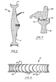
- Figure 1 is a partially sectioned side view of a solid wheel formed according to the teachings of the present invention;
- Figure 2 is a sectional view taken along line II - II of Figure 1;
- Figure 3 is an edge view of the solid wheel of Figure 1;
- Figure 4 is an enlarged, partial sectional view of the machining operation;
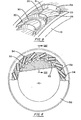
- Figure 5 is a sectional view of a turbine;
- Figure 6 is a partially sectioned view of the wheel and nozzle ring;
- Figure 7 is a sectional view taken along line VII - VII of Figure 6;
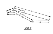
- Figure 8 is a pictorial representation of the flow in a bucket; and
- Figure 9 is velocity diagram.
- In Figures 1-8, the
numeral 10 generally designates the solid wheel of aturbine 100.Wheel 10 is initially formed as a blank such as a forging. Prior to the forming of the buckets, the rim of thewheel 10 is preferably profiled by machining anarcuate groove 14 therein,. as is best seen in Figure 4. Preferably, thegroove 14 forms a segment of an ellipse, since the buckets are wider than they are deep, so as to reduce the amount of material to be removed in a milling operation.Labyrinth seal lands 12 are machined on thedownstream face 11 ofwheel 10. Thebuckets 20 are then individually machined into the profiledgroove 14 as by an end mill, by transverse milling or cutting. In the illustrated embodiment, themilling tool 30 is of a diameter less than the axial extent of the rim of thewheel 10 and tends to machine out a slot terminating in a semicircular opening or pocket with aflat bottom 22, which is best viewed in Figure 4.Flat bottom 22 forms a portion of the base of a cylinder andwall 24 forms a portion of the side of a cylinder. Themilling tool 30 goes from the Figure 1 position to the Figure 4 position for each bucket. However, the axis of thetool 30 is located on a non-diametrical chord preferably such that at point A, which is the top of the rearmost point of thewall 24 of eachbucket 20, thewall 24 makes an angle of 10° to 30°, with 15° preferred, with a radius of thewheel 10. The exact angle will be a function of the diameter and thickness of the wheel, as well as the number and depth of the buckets which are determined by the design turbine speed and steam pressure. However, as best shown in Figure 4, the location and depth of each bucket cut, taken in isolation, is such that a portion of thetool 30 extends past the rim ofwheel 10 at the full depth of the cut. As best shown in Figures 3 and 8 this results in a cut approximating the major portion of a circle, when viewed along the axis of thetool 30 at the full cut, and is of a generally crescent shape after the cutting of the adjacent bucket. Eachbucket 20 has a local minimum depth or vertical extent at point A which is in the middle of the bight ofwall 24. The vertical extent ofwall 24 increases from point A to points B which represent the greatest vertical extent and are the locations where the bight ofwall 24 meets the outer rim diameter. The arc BAB forms a portion of an ellipse since it is not parallel tobottom 22. The vertical, extent ofwall 24 reduces to zero at the ends of the crescent or points C. When formed as described above, eachbucket 20 has a considerable thickness of the wheel backing it up so that bucket failure is essentially eliminated. - In Figure 5, the
numeral 100 generally designates an impulse turbine employing thesolid wheel 10 of the present invention. Turbine 100 includes aninlet casing 40 and anexhaust volute casing 44.Inlet casing 40 consists of a short flanged inlet pipe for connection to the steam source on one side and a flangedinlet cone 41 on the other end.Inlet casing 40 serves as the connection between the steam source and the turbine.Exhaust volute casing 44 serves as a collector for the exhaust steam and a housing for other turbine components.Wheel 10 is supported in an overhanging fashion by bearing 46 which supportsshaft 48.Nozzle ring 50 is supported byturbine casing 42 radially outward ofwheel 10. As best shown in Figures 6 and 7,nozzle ring 50 has a plurality of uniformly spaced, generally tangentiallydischarging passages 52, each having anozzle 54 located at the inlet end of the passage. Additionally,nozzle ring 50 supports abradible,replaceable seal 56 which separates the inlet and outlet portions of thebuckets 20. A normal running clearance of .030 to .045 inches provides the necessary preferred seal for an impulse stage. - As is conventional in impulse turbines, steam is supplied to
turbine 100 viainlet casing 40 and is directed byinlet cone 41 and inlet guide vanes (not illustrated) to thenozzle ring 50. The steam then passes throughnozzles 54 intopassages 52 and tangentially enters thebuckets 20. - The steam enters each bucket on one side and is turned through i50° - 180° by the
wall 24 and exits via the other side of the bucket and passes into theexhaust volute casing 44. In passing through thebuckets 20 and being turned, the steam imparts kinetic energy to thewheel 10 causing it to rotate together withshaft 48 and any power generating equipment connected thereto (not illustrated). This operation does not significantly differ from that of a conventional impulse turbine. However, the bucket configuration of the present invention provides considerable advantages when used with low quality/wet steam or dirty gas. As described above, the steam impinging upon thewalls 24 of thebuckets 20 imparts kinetic energy to thewheel 10 causing it to rotate in the same direction which the steam is supplied. At operating speed, the wheel tip speed is about 40 to 60% that of the steam being supplied by thenozzles 54. With wet steam, the velocity of the water droplets is much less than that of the steam as well as that of thewheel 10 so that the wheel overtakes the water droplets. In a conventional bucket configuration, the unloaded upstream leading edge of the buckets would overtake and impinge against the water droplets and be eroded thereby. However, ' when thebuckets 20 are configured in accordance with the teachings of the present invention, the leading edge portion of the conventional bucket does not exist and therefore cannot be eroded by 90° impingement. Referring now to Figure 8, as indicated byarrow 90, steam enters the movingbucket 20 with a relative velocity and flows along thewall 24 and is turned through 150° - 180° before exiting from thebucket 20. The water droplets contained in the steam, as indicated byarrow 91, have a negative relative velocity with respect to thebucket 20 and so is overtaken by therotating wheel 10 such that the water droplets impinge against theflat bottoms 22 of thebuckets 20 at a very low angle of incidence which is not conducive to erosion. The droplets impinging upon thebottoms 22 flow over the edge of the bucket and downwall 24 whereupon the droplets are reentrained in the steam, as indicated by thearrow 90, and pass from thebucket 20. Figure 9 is a velocity diagram of the steam (gas) and water droplet flow. In the diagram the wheel velocity, u, the relative gas velocity entering thebucket 20, Wl, and the absolute gas velocity leaving the nozzle, Cl, form a triangle representing the gas flow. Superimposed upon this triangle is a second velocity diagram wherein the wheel velocity, u, the absolute water droplet velocity, C2, and the relative water droplet velocity impinging upon bucket bottom 22, W21 form a second triangle representing the droplet flow. - Although a preferred embodiment of the present invention used in a steam turbine has been described an illustrated, other changes will occur to those skilled in the art. It is therefore intended that the scope of the present invention is to be limited only by the scope of the appended claims.
Claims (5)
Applications Claiming Priority (2)
| Application Number | Priority Date | Filing Date | Title |
|---|---|---|---|
| US39001482A | 1982-06-21 | 1982-06-21 | |
| US390014 | 1995-02-17 |
Publications (3)
| Publication Number | Publication Date |
|---|---|
| EP0097605A2 true EP0097605A2 (en) | 1984-01-04 |
| EP0097605A3 EP0097605A3 (en) | 1984-10-10 |
| EP0097605B1 EP0097605B1 (en) | 1987-08-19 |
Family
ID=23540689
Family Applications (1)
| Application Number | Title | Priority Date | Filing Date |
|---|---|---|---|
| EP19830630094 Expired EP0097605B1 (en) | 1982-06-21 | 1983-06-02 | High speed supersonic impulse turbine |
Country Status (3)
| Country | Link |
|---|---|
| EP (1) | EP0097605B1 (en) |
| JP (1) | JPS597701A (en) |
| DE (1) | DE3373119D1 (en) |
Cited By (4)
| Publication number | Priority date | Publication date | Assignee | Title |
|---|---|---|---|---|
| EP0362836A1 (en) * | 1988-10-06 | 1990-04-11 | B a r m a g AG | Yarn winding machine |
| GB2270543A (en) * | 1992-09-02 | 1994-03-16 | John Kirby | Turbines. |
| US5427499A (en) * | 1992-09-02 | 1995-06-27 | Kirby; John | Turbines having depressions in the working members thereof |
| CN106368753A (en) * | 2016-11-18 | 2017-02-01 | 蔡述强 | Impeller pressurizing device |
Families Citing this family (1)
| Publication number | Priority date | Publication date | Assignee | Title |
|---|---|---|---|---|
| JP2581199Y2 (en) * | 1990-04-24 | 1998-09-21 | 村角工業 株式会社 | Medical examination cassette |
Citations (5)
| Publication number | Priority date | Publication date | Assignee | Title |
|---|---|---|---|---|
| DE164340C (en) * | ||||
| FR349490A (en) * | 1904-12-23 | 1905-05-30 | Maschb Actien Ges Union | Method for milling u-shaped pockets in turbine wheels |
| US1965817A (en) * | 1932-10-24 | 1934-07-10 | Wessel Walter | Turbine |
| GB1416442A (en) * | 1972-03-15 | 1975-12-03 | Secr Defence | Turbomachinery |
| US4295788A (en) * | 1980-03-10 | 1981-10-20 | Terry Corporation | Turbine wheel and nozzle arrangement |
Family Cites Families (1)
| Publication number | Priority date | Publication date | Assignee | Title |
|---|---|---|---|---|
| JPS4933022A (en) * | 1972-08-03 | 1974-03-26 |
-
1983
- 1983-06-02 EP EP19830630094 patent/EP0097605B1/en not_active Expired
- 1983-06-02 DE DE8383630094T patent/DE3373119D1/en not_active Expired
- 1983-06-21 JP JP11178683A patent/JPS597701A/en active Pending
Patent Citations (5)
| Publication number | Priority date | Publication date | Assignee | Title |
|---|---|---|---|---|
| DE164340C (en) * | ||||
| FR349490A (en) * | 1904-12-23 | 1905-05-30 | Maschb Actien Ges Union | Method for milling u-shaped pockets in turbine wheels |
| US1965817A (en) * | 1932-10-24 | 1934-07-10 | Wessel Walter | Turbine |
| GB1416442A (en) * | 1972-03-15 | 1975-12-03 | Secr Defence | Turbomachinery |
| US4295788A (en) * | 1980-03-10 | 1981-10-20 | Terry Corporation | Turbine wheel and nozzle arrangement |
Cited By (5)
| Publication number | Priority date | Publication date | Assignee | Title |
|---|---|---|---|---|
| EP0362836A1 (en) * | 1988-10-06 | 1990-04-11 | B a r m a g AG | Yarn winding machine |
| US4932598A (en) * | 1988-10-06 | 1990-06-12 | Barmag Ag | Yarn winding machine |
| GB2270543A (en) * | 1992-09-02 | 1994-03-16 | John Kirby | Turbines. |
| US5427499A (en) * | 1992-09-02 | 1995-06-27 | Kirby; John | Turbines having depressions in the working members thereof |
| CN106368753A (en) * | 2016-11-18 | 2017-02-01 | 蔡述强 | Impeller pressurizing device |
Also Published As
| Publication number | Publication date |
|---|---|
| EP0097605B1 (en) | 1987-08-19 |
| EP0097605A3 (en) | 1984-10-10 |
| JPS597701A (en) | 1984-01-14 |
| DE3373119D1 (en) | 1987-09-24 |
Similar Documents
| Publication | Publication Date | Title |
|---|---|---|
| EP0032815B1 (en) | Two-phase reaction turbine | |
| KR100393725B1 (en) | Gas turbine bucket | |
| US4086022A (en) | Gas turbine engine with improved compressor casing for permitting higher air flow and pressure ratios before surge | |
| US2918254A (en) | Turborunner | |
| US6142739A (en) | Turbine rotor blades | |
| EP0092955A2 (en) | Method and apparatus for controlling the fluid boundary layer in a compressor | |
| US4066381A (en) | Turbine stator nozzles | |
| US20150110617A1 (en) | Turbine airfoil including tip fillet | |
| US11603852B2 (en) | Compressor bleed port structure | |
| EP0097608B1 (en) | Turbine wheel having buckets or blades machined into the outer circumference of the wheel | |
| GB2155558A (en) | Turbomachinery rotor blades | |
| JP7012825B2 (en) | Turbine blades and corresponding delivery methods | |
| US2806645A (en) | Radial diffusion compressors | |
| Yu et al. | The experimental researches on improving operating stability of a single stage transonic fan | |
| GB1301002A (en) | Improvements relating to fluid-flow machines | |
| EP0097605B1 (en) | High speed supersonic impulse turbine | |
| EP3740656B1 (en) | Article of manufacture | |
| US2962206A (en) | Centrifugal compressor for a gas turbine engine | |
| US4573870A (en) | Solid turbine wheel with guided discharge | |
| GB1605282A (en) | Bladed rotor for gas turbine engine | |
| US3525213A (en) | Gas turbine engine with aerodynamic torque converter drive | |
| US3079126A (en) | Turbine systems | |
| Najjar et al. | Effect of prewhirl on the performance of centrifugal compressors | |
| SU1041712A2 (en) | Outlet pipe of steam turbine | |
| US3368794A (en) | Reentry turbine |
Legal Events
| Date | Code | Title | Description |
|---|---|---|---|
| PUAI | Public reference made under article 153(3) epc to a published international application that has entered the european phase |
Free format text: ORIGINAL CODE: 0009012 |
|
| AK | Designated contracting states |
Designated state(s): CH DE FR GB IT LI SE |
|
| PUAL | Search report despatched |
Free format text: ORIGINAL CODE: 0009013 |
|
| AK | Designated contracting states |
Designated state(s): CH DE FR GB IT LI SE |
|
| 17P | Request for examination filed |
Effective date: 19841212 |
|
| GRAA | (expected) grant |
Free format text: ORIGINAL CODE: 0009210 |
|
| AK | Designated contracting states |
Kind code of ref document: B1 Designated state(s): CH DE FR GB IT LI SE |
|
| ET | Fr: translation filed | ||
| REF | Corresponds to: |
Ref document number: 3373119 Country of ref document: DE Date of ref document: 19870924 |
|
| ITF | It: translation for a ep patent filed | ||
| PLBE | No opposition filed within time limit |
Free format text: ORIGINAL CODE: 0009261 |
|
| STAA | Information on the status of an ep patent application or granted ep patent |
Free format text: STATUS: NO OPPOSITION FILED WITHIN TIME LIMIT |
|
| 26N | No opposition filed | ||
| PG25 | Lapsed in a contracting state [announced via postgrant information from national office to epo] |
Ref country code: GB Effective date: 19890602 |
|
| PG25 | Lapsed in a contracting state [announced via postgrant information from national office to epo] |
Ref country code: SE Effective date: 19890603 |
|
| PG25 | Lapsed in a contracting state [announced via postgrant information from national office to epo] |
Ref country code: LI Effective date: 19890630 Ref country code: CH Effective date: 19890630 |
|
| GBPC | Gb: european patent ceased through non-payment of renewal fee | ||
| PG25 | Lapsed in a contracting state [announced via postgrant information from national office to epo] |
Ref country code: FR Free format text: LAPSE BECAUSE OF NON-PAYMENT OF DUE FEES Effective date: 19900228 |
|
| REG | Reference to a national code |
Ref country code: CH Ref legal event code: PL |
|
| PG25 | Lapsed in a contracting state [announced via postgrant information from national office to epo] |
Ref country code: DE Effective date: 19900301 |
|
| REG | Reference to a national code |
Ref country code: FR Ref legal event code: ST |
|
| EUG | Se: european patent has lapsed |
Ref document number: 83630094.7 Effective date: 19900418 |