EP3161908B1 - Élément de connexion de câble - Google Patents
Élément de connexion de câble Download PDFInfo
- Publication number
- EP3161908B1 EP3161908B1 EP15731354.5A EP15731354A EP3161908B1 EP 3161908 B1 EP3161908 B1 EP 3161908B1 EP 15731354 A EP15731354 A EP 15731354A EP 3161908 B1 EP3161908 B1 EP 3161908B1
- Authority
- EP
- European Patent Office
- Prior art keywords
- cable
- wire
- connection component
- spring arms
- arms
- Prior art date
- Legal status (The legal status is an assumption and is not a legal conclusion. Google has not performed a legal analysis and makes no representation as to the accuracy of the status listed.)
- Active
Links
Images


Classifications
-
- H—ELECTRICITY
- H01—ELECTRIC ELEMENTS
- H01R—ELECTRICALLY-CONDUCTIVE CONNECTIONS; STRUCTURAL ASSOCIATIONS OF A PLURALITY OF MUTUALLY-INSULATED ELECTRICAL CONNECTING ELEMENTS; COUPLING DEVICES; CURRENT COLLECTORS
- H01R9/00—Structural associations of a plurality of mutually-insulated electrical connecting elements, e.g. terminal strips or terminal blocks; Terminals or binding posts mounted upon a base or in a case; Bases therefor
- H01R9/03—Connectors arranged to contact a plurality of the conductors of a multiconductor cable, e.g. tapping connections
- H01R9/05—Connectors arranged to contact a plurality of the conductors of a multiconductor cable, e.g. tapping connections for coaxial cables
- H01R9/0527—Connection to outer conductor by action of a resilient member, e.g. spring
-
- H—ELECTRICITY
- H01—ELECTRIC ELEMENTS
- H01R—ELECTRICALLY-CONDUCTIVE CONNECTIONS; STRUCTURAL ASSOCIATIONS OF A PLURALITY OF MUTUALLY-INSULATED ELECTRICAL CONNECTING ELEMENTS; COUPLING DEVICES; CURRENT COLLECTORS
- H01R13/00—Details of coupling devices of the kinds covered by groups H01R12/70 or H01R24/00 - H01R33/00
- H01R13/46—Bases; Cases
- H01R13/502—Bases; Cases composed of different pieces
- H01R13/512—Bases; Cases composed of different pieces assembled by screw or screws
-
- H—ELECTRICITY
- H01—ELECTRIC ELEMENTS
- H01R—ELECTRICALLY-CONDUCTIVE CONNECTIONS; STRUCTURAL ASSOCIATIONS OF A PLURALITY OF MUTUALLY-INSULATED ELECTRICAL CONNECTING ELEMENTS; COUPLING DEVICES; CURRENT COLLECTORS
- H01R13/00—Details of coupling devices of the kinds covered by groups H01R12/70 or H01R24/00 - H01R33/00
- H01R13/46—Bases; Cases
- H01R13/52—Dustproof, splashproof, drip-proof, waterproof, or flameproof cases
- H01R13/5205—Sealing means between cable and housing, e.g. grommet
-
- H—ELECTRICITY
- H01—ELECTRIC ELEMENTS
- H01R—ELECTRICALLY-CONDUCTIVE CONNECTIONS; STRUCTURAL ASSOCIATIONS OF A PLURALITY OF MUTUALLY-INSULATED ELECTRICAL CONNECTING ELEMENTS; COUPLING DEVICES; CURRENT COLLECTORS
- H01R13/00—Details of coupling devices of the kinds covered by groups H01R12/70 or H01R24/00 - H01R33/00
- H01R13/58—Means for relieving strain on wire connection, e.g. cord grip, for avoiding loosening of connections between wires and terminals within a coupling device terminating a cable
- H01R13/582—Means for relieving strain on wire connection, e.g. cord grip, for avoiding loosening of connections between wires and terminals within a coupling device terminating a cable the cable being clamped between assembled parts of the housing
- H01R13/5825—Means for relieving strain on wire connection, e.g. cord grip, for avoiding loosening of connections between wires and terminals within a coupling device terminating a cable the cable being clamped between assembled parts of the housing the means comprising additional parts captured between housing parts and cable
-
- H—ELECTRICITY
- H01—ELECTRIC ELEMENTS
- H01R—ELECTRICALLY-CONDUCTIVE CONNECTIONS; STRUCTURAL ASSOCIATIONS OF A PLURALITY OF MUTUALLY-INSULATED ELECTRICAL CONNECTING ELEMENTS; COUPLING DEVICES; CURRENT COLLECTORS
- H01R13/00—Details of coupling devices of the kinds covered by groups H01R12/70 or H01R24/00 - H01R33/00
- H01R13/62—Means for facilitating engagement or disengagement of coupling parts or for holding them in engagement
- H01R13/622—Screw-ring or screw-casing
-
- H—ELECTRICITY
- H01—ELECTRIC ELEMENTS
- H01R—ELECTRICALLY-CONDUCTIVE CONNECTIONS; STRUCTURAL ASSOCIATIONS OF A PLURALITY OF MUTUALLY-INSULATED ELECTRICAL CONNECTING ELEMENTS; COUPLING DEVICES; CURRENT COLLECTORS
- H01R43/00—Apparatus or processes specially adapted for manufacturing, assembling, maintaining, or repairing of line connectors or current collectors or for joining electric conductors
- H01R43/20—Apparatus or processes specially adapted for manufacturing, assembling, maintaining, or repairing of line connectors or current collectors or for joining electric conductors for assembling or disassembling contact members with insulating base, case or sleeve
-
- H—ELECTRICITY
- H01—ELECTRIC ELEMENTS
- H01R—ELECTRICALLY-CONDUCTIVE CONNECTIONS; STRUCTURAL ASSOCIATIONS OF A PLURALITY OF MUTUALLY-INSULATED ELECTRICAL CONNECTING ELEMENTS; COUPLING DEVICES; CURRENT COLLECTORS
- H01R13/00—Details of coupling devices of the kinds covered by groups H01R12/70 or H01R24/00 - H01R33/00
- H01R13/58—Means for relieving strain on wire connection, e.g. cord grip, for avoiding loosening of connections between wires and terminals within a coupling device terminating a cable
- H01R13/582—Means for relieving strain on wire connection, e.g. cord grip, for avoiding loosening of connections between wires and terminals within a coupling device terminating a cable the cable being clamped between assembled parts of the housing
- H01R13/5829—Means for relieving strain on wire connection, e.g. cord grip, for avoiding loosening of connections between wires and terminals within a coupling device terminating a cable the cable being clamped between assembled parts of the housing the clamping part being flexibly or hingedly connected to the housing
-
- H—ELECTRICITY
- H01—ELECTRIC ELEMENTS
- H01R—ELECTRICALLY-CONDUCTIVE CONNECTIONS; STRUCTURAL ASSOCIATIONS OF A PLURALITY OF MUTUALLY-INSULATED ELECTRICAL CONNECTING ELEMENTS; COUPLING DEVICES; CURRENT COLLECTORS
- H01R13/00—Details of coupling devices of the kinds covered by groups H01R12/70 or H01R24/00 - H01R33/00
- H01R13/58—Means for relieving strain on wire connection, e.g. cord grip, for avoiding loosening of connections between wires and terminals within a coupling device terminating a cable
- H01R13/59—Threaded ferrule or bolt operating in a direction parallel to the cable or wire
-
- H—ELECTRICITY
- H01—ELECTRIC ELEMENTS
- H01R—ELECTRICALLY-CONDUCTIVE CONNECTIONS; STRUCTURAL ASSOCIATIONS OF A PLURALITY OF MUTUALLY-INSULATED ELECTRICAL CONNECTING ELEMENTS; COUPLING DEVICES; CURRENT COLLECTORS
- H01R4/00—Electrically-conductive connections between two or more conductive members in direct contact, i.e. touching one another; Means for effecting or maintaining such contact; Electrically-conductive connections having two or more spaced connecting locations for conductors and using contact members penetrating insulation
- H01R4/24—Connections using contact members penetrating or cutting insulation or cable strands
- H01R4/2416—Connections using contact members penetrating or cutting insulation or cable strands the contact members having insulation-cutting edges, e.g. of tuning fork type
- H01R4/242—Connections using contact members penetrating or cutting insulation or cable strands the contact members having insulation-cutting edges, e.g. of tuning fork type the contact members being plates having a single slot
- H01R4/2425—Flat plates, e.g. multi-layered flat plates
- H01R4/2429—Flat plates, e.g. multi-layered flat plates mounted in an insulating base
- H01R4/2433—Flat plates, e.g. multi-layered flat plates mounted in an insulating base one part of the base being movable to push the cable into the slot
Definitions
- the invention relates to a cable connection component for electrically connecting a shielded multicore cable, having an internal thread having a union nut, with a multiple incisions splice piece of insulating material for singling the wires of the cable and with a shielding element for contacting the shield of the cable, wherein the core insulation of in the splice part introduced wire ends when screwing the nut on a provided with an internal thread corresponding to the external thread provided electrically conductive connection body arranged in the connection body and plunging into the incisions in the splice cutting terminals and contacts the conductors of the wires.
- the invention also relates to a cable connection device and a cable connection device with a cable connection component according to the invention and a device connection component or a cable connection component and a method for mounting a shielding element in a splice part of a cable connection component according to the invention.
- a cable connection component is known as part of a cable connection device with which the wires of a multicore cable can be connected in a simple manner to the connection elements of a device connection component or a cable connection component, without first having to remove the core insulation of the individual conductors.
- the individual wires of the cable are first introduced into the splice part, which is referred to there as a wire receiving and - Adjuststeil.
- the wire ends are bent and inserted into recesses in the splice part, which serve as restraint locks for the wires during radial deflection. Subsequently, the protruding through the recesses wire ends are cut off, so that then the union nut can be screwed onto the corresponding external thread of a connector body.
- the splice member is pressed into the connector body, wherein the cutting terminals arranged in the connector body penetrate into the incisions provided in the splice part, thereby penetrating the core insulation of the individual wires crossing the incisions and contacting the individual conductors.
- connection component consists of an inner clamping part, along the lateral surface of which a plurality of recesses for the individual wires are arranged, in which clamping ribs are formed, which clamp the wires in the recesses.
- connection component has a positioning sleeve which can be pushed onto the clamping part.
- the positioning sleeve has radially inwardly directed, wedge-shaped webs which force the individual conductors into an S-shaped path.
- shielded cables are used to prevent capacitive and inductive electromagnetic couplings in the cable.
- one end of the shielded cable is often connected via a plug connector or a cable connection device to an electrical device, for example a sensor-actuator box, and the other end to the supply connection, for example via a terminal block.
- the contacting of the shield of the cable is done on the side of the device mostly via the metallic sleeve of the connector or the Connecting body, via which the shield is connected to the metallic housing of the electrical device.
- the DE 37 34 667 C1 discloses a cable end plug for mounting on a coaxial cable, which is inserted together with the remote end of the coaxial cable in a plug device of a connection device.
- the cable end plug has two plug sleeve parts made of plastic, between which an annular contact sleeve is arranged.
- the contact sleeve has an annular disk as a central portion and on both sides of the central portion angeodnete, individual contact tongues.
- the outer contact tongues serve for contacting the conductive inner wall of the plug-in device and the inner contact tongues for contacting the outer conductor of the coaxial cable.
- the DE 20 2008 004 892 U1 Therefore proposes the use of a cup-shaped, a bottom and an angled collar having screen transfer element that is plugged onto the cable to be connected facing side of the splice.
- the exposed shielding of the cable is guided outwardly over the collar of the shielding element such that the shielding contacts the external thread of the plug sleeve when the screwed connection is screwed onto it in an electrically conductive manner.
- the disadvantage here is that to ensure safe forwarding of the shielding the shielding must be placed before connecting the wires of the cable by hand on the collar of the screen transfer element.
- a cable connection component described above is known in which a shielding element is arranged inside the splice part, where it is referred to as a guide device.
- the shielding element is designed as a funnel-shaped catching device, which has an annular base part and four in the direction of the longitudinal axis of the splice part or the cable connection component inwardly bent spring elements.
- one of the spring elements is connected to a line element extending in the longitudinal direction of the cable connection component, which, like the wires of the cable to be connected, is inserted into the splicing part.
- connection body insulation displacement terminal When screwing the union nut on the external thread of the connector body, the line element as the cores of the cable is then contacted by an arranged in the connection body insulation displacement terminal.
- the electrically conductive connection of the shielding of the cable via the shielding element and the line element thus takes place only with one of the contacts arranged in the connection body.
- the invention is therefore based on the object to provide a cable connection component or a cable connection device and a cable connection direction, which is a simple connection of a shielded multicore Cable allows. On a special preparation of the shielding of the cable should be omitted as possible.
- the shielding element has an annular central portion, a plurality of extending from the central portion in the direction of the wire guide member side facing inner spring arms and a plurality of the central portion in the direction of the wire guide part remote from the side extending outer spring arms.
- the inner spring arms are bent inwardly in the direction of the longitudinal axis of the cable connection component in such a way that their ends contact the shielding of a connected cable, while the outer spring arms are bent away from the longitudinal axis of the cable connection component in such a way that the outer spring arms between the cable receiving part and the wire guide member, wherein the ends of the outer spring arms protrude from the splice member.
- the splice part is formed in two parts, namely consists of a cable receiving part and a wire guide part, the possibility has been created in a simple manner to contact the arranged inside the splice part shielding of the cable via the shielding element on the outer circumference of the splice. Due to the fact that the shielding element has a plurality of outer spring arms, a connection of the shield to the metallic connector body at several distributed over the circumference points, which is desirable for a good shield connection. Due to the resilient property of the inner spring arms, the contacting of the shielding of the cable takes place automatically upon insertion of the cable into the cable connection component or into the cable receiving part of the splice part, so that a special, additional preparation of the shield is not required. The connection of the shielded cable is rather as the installer knows from the connection of an unshielded cable to a known from the prior art cable connection component.
- the latching arms of the cable receiving part are arranged concentrically to the longitudinal axis of the cable connection component, wherein in the assembled state of cable receiving part and wire guide part facing the cable connection component sleeve-shaped portion of the wire guide part surrounding the latching arms.
- the sleeve-shaped region of the wire guide part is thus simply plugged onto the latching arms for connection to the cable receiving part, wherein the latching arms engage with the corresponding latching hooks arranged in the interior of the sleeve-shaped region, so that the cable receiving part and the wire guide part are securely connected to one another.
- connection area between the cable receiving part and the wire guide part is mechanically protected and beyond the sealing of extending within the latching arms of the cable receiving part wires of the cable.
- the two-part design of the splice part has made it possible to contact via the shielding element the shielding of the cable to be connected outside the splicing part, namely the metallic connecting body, arranged in the interior of the splicing part.
- the shielding element between the cable receiving part and the wire guide part is arranged, wherein according to a preferred embodiment of the invention, the annular central portion of the Schirmungselements, which connects the inner spring arms with the outer spring arms, is surrounded by the latching arms of the cable receiving part, ie the annular central portion is disposed within the cable receiving portion.
- the outer spring arms of the Schirmungselements extend through the individual free spaces between the latching arms of the cable receiving part.
- the inner spring arms of the shielding element are preferably arranged corresponding to the latching arms of the cable receiving part, ie the inner spring arms and the latching arms have the same angular position in the mounted state.
- the inner spring arms and the outer spring arms are arranged evenly distributed on the circumference of the central portion.
- the invention also relates to a cable connection device for the electrically conductive connection of a shielded multicore cable to an electrical device.
- the electrical device may be, for example, a sensor / actuator box. Regardless of this, however, the term “electrical device” is to be understood here in a general way, that is to say, “electrical device”. H.
- the term “electrical device” is intended to include other electrical components, devices and devices.
- Such a cable connection device has, in addition to the previously described cable connection component, a device connection component which has a metallic connection body with an external thread corresponding to the internal thread of the union nut.
- a plurality of insulation displacement terminals and connection elements connected to the individual insulation displacement terminals are provided in the connection body, wherein the insulation displacement terminals are arranged on the side facing the cable connection component side and the connection elements on the side facing away from the cable connection component side.
- these are integrally formed metal parts which are formed on one side as insulation displacement terminals and on the other side as connection elements.
- the connection elements may preferably be designed as pin or socket contacts.
- the present invention also relates to a cable connection device for the electrically conductive connection of two shielded multicore cables.
- a cable connecting device which is often referred to as a cable connector
- the cable connection component in addition to the cable connection component according to the invention still has a cable connection component.
- the cable connection component has a connection body with an external thread corresponding to the internal thread of the union nut and a plurality of insulation displacement terminals and connection elements arranged in the connection body.
- the insulation displacement terminals on the side facing the cable connection component and the connection elements on the opposite side are also arranged in the cable connection component, wherein the insulation displacement terminals and the connection elements are in turn electrically conductively connected to one another.
- connection elements of the cable connection component which serve to connect the wires of the second cable
- connection techniques known to the person skilled in the art for example screw connection or spring terminal connection
- the connection elements of the cable connection component are formed as insulation displacement terminals, so that in the connection body of the cable connection component a plurality of metal parts are arranged, which are formed on both sides as insulation displacement terminals.
- the connection body then has a second external thread, onto which the union nut of a second cable connection component can be screwed and thus a splice part can be inserted into the connection body.
- the expansion of the latching arms of the cable receiving part is preferably carried out by means of a dome, which is inserted from the side facing away from the wire guide part in the cable receiving part. If the shielding element is inserted between the latching arms of the cable receiving part, then the mandrel is pulled out of the cable receiving part, so that the latching arms spring back and thereby radially fix the shielding element in its end position.
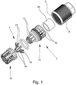
- the Fig. 1 shows a cable connection component 1 according to the invention for connecting a in the Fig. 2 and 7
- the cable 2 has a plurality of wires 21, a shielding 22 surrounding all cores 21 together and a cable jacket 23 surrounding the shielding 22.
- To the cable connection component 1 in particular include an internal thread 3 having a union nut 4, a plurality of incisions 5 having splice 6 of insulating material and a shielding element 7.
- Fig. 3 again splice part 6 shown from a cable receiving part 11 and a latchable with the cable receiving part 11 sleeve-shaped wire guide part 12.
- the cable receiving part 11 has a plurality of resilient latching arms 13 and the wire guide part 12 to the latching arms 13, inwardly, ie in the direction of the longitudinal axis of the wire guide part 12 facing latching hooks 14.
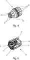
- shielding element 7 consists of an approximately annular central portion 15, a plurality of the central portion 15 in the direction of the wire guide member 12 side facing extending inner spring arms 16 and more from the central portion 15 in the direction of the wire guide member 12 side facing outer spring arms 17.
- the inner spring arms 16 are bent inwardly in the direction of the longitudinal axis of the cable connection component 1 in such a way that the ends of the inner spring arms contact the shield 22 of a connected cable 2.
- the outer spring arms 17 are bent from the annular central portion 15 to the outside, ie bent away from the longitudinal axis of the cable connection component 1.
- the outer spring arms 17 extend between the cable receiving part 11 and the wire guide part 12, so that the ends 18 of the outer spring arms 17 protrude outwardly from the splice part 6.
- the latching arms 13 are arranged concentrically to the longitudinal axis of the cable connection component 1 in the assembled state of the cable receiving part 11 and wire guide part 12 of a sleeve-shaped portion 19 of the wire guide part 12 facing the cable receiving part 11.
- the sleeve-shaped portion 19 of the wire guide part 12 encloses the latching arms 13 of the cable receiving part 11, an unintentional release of the latching connection between the cable receiving part 11 and the wire guide part 12 during insertion of the splice member 6 is prevented in the connector body 9.
- Fig. 3 shows the splice member 6 in the assembled state, wherein the annular central portion 15 of the Schirmungselements 7 disposed within the cable receiving part 11, namely surrounded by the latching arms 13.
- the outer spring arms 17 of the Schirmungselements 7 extend through the spaces 20 between the individual locking arms 13. It can be seen that both the inner spring arms 16 and the outer spring arms 17 are arranged evenly distributed on the circumference of the central portion 15, wherein the inner spring arms 16 are arranged offset to the outer spring arms 17 so that the inner spring arms 16 have the same angular position as the latching arms 13, so that in each case an inner spring arm 16 is covered by a corresponding latching arm 13.
- the width of the inner spring arms 16 is reduced from the central portion 15 towards its end, the ends being bent outwardly to facilitate the contacting of the shield 22 of the cable 2.
- the opening formed by the free ends of the inner spring arms 16 has a diameter which is slightly smaller than the outer diameter of the shield 22, so that upon insertion of a cable 2 through the Schirmungselement 7, the inner spring arms 16 are slightly deflected. As a result, a secure and good electrical contacting of the shield 22 is ensured by the ends of the inner spring arms 16.
- the width of the outer spring arms 17 increases from the central portion 15 to their ends 18, the ends 18 being approximately V-shaped in the illustrated embodiment. In this way, it is achieved that the ends 18 of the outer spring arms 17 projecting outward from the splicing part 6 make contact with the inner circumference of the metallic connecting body 9 at a plurality of points distributed over the circumference of the connecting body 9. At the same time, the splitting of the ends 18 of the outer spring arms 17 increases their elasticity, which likewise has a positive effect on the electrical connection between the ends 18 of the outer spring arms 17 and the inner surface of the metallic connection body 9.
- the cable connection component 1 still has an annular seal 24, which forms a Switzerlandentlastungs- and sealing area together with a plurality of annularly formed on the cable receiving part 11 fins 25.
- the slats 25 cooperate when screwing the union nut 4 with a provided on the inside of the union nut 4 bevel in the manner of a PG gland, so that when screwing the nut 4 on the connector body 9, the fins 25 are pressed against the seal 24, resulting in a seal and at the same time a strain relief of an inserted cable 2.
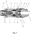
- the cable connection device 26 comprises a cable connection component 1 and a device connection component 27.
- the device connection component 27 has a metallic connection body 9 with an external thread 8 and a number of insulation displacement terminals 10 corresponding to the number of leads 21 to be connected and connection elements 28 connected in an electrically conductive manner to the insulation displacement terminals 10.
- the connection elements 28 are designed as pin contacts, which are each soldered or welded to the insulation displacement terminals 10.
- the device connection component 27 is formed as a connector.
- the connection body 9 has on the side facing away from the cable connection component 1 a second external thread 29, which is rotatable and thus can be screwed into a corresponding junction box.
- the latching arms 13 of the cable receiving part 11 are first widened, so that the shielding element 7 can be inserted with its middle section 15 between the latching arms 13.
- the outer spring arms 17 extend through the free spaces 20 between the latching arms 13, so that the ends 18 of the outer spring arms 17 protrude laterally from the cable receiving part 11. If the shielding element 7 is completely inserted between the latching arms 13 of the cable receiving part 11 and the expansion of the latching arms 13 is canceled, then the middle section 15 is clamped between the latching arms 13, so that the shielding element 7 is fixed radially in its position.
- the wire guide member 12 is fitted with its sleeve-shaped portion 19 on the cable receiving part 11, wherein the latching hooks 14 engage with the latching arms 13.
- the portions of the outer spring arms 17 projecting laterally from the cable receiving part 11 are pressed by the end face of the wire guide part 12 facing the cable receiving part 11 against a stop collar 30 formed on the cable receiving part 11, so that the shielding element 7 is also fixed axially in its position.
- the cable 2 is first introduced into the cable connection component 1 by the end of the cable 2 is pushed through the rear opening in the union nut 4 as far into the splice member 6, that the individual wire ends on the union nut 4 facing away from the splice 6 and the wire guide part 12 protrude. Subsequently, the individual wire ends are folded by about 90 ° to the outside and pressed into the formed in the wire guide part 12 recesses 31, which serve as restraint locks for the wire ends (see. Fig. 2 ).
- the shielding 22 of the cable 2 is automatically contacted by the ends of the inner spring arms 16, so that no additional steps are required for contacting the shielding 22 of the cable 2.
- the splice member 6 When screwing the union nut 4 on the external thread 8 of the metallic terminal body 9, the splice member 6 is inserted into the connector body 9, wherein the arranged in the connector body 9 insulation displacement plugs 10 in the core guide member 12 formed, dive open at the front incisions 5, whereby a reliable contact of the Incisions 5 crossing, outwardly folded wire ends is ensured by the insulation displacement terminals 10.
Landscapes
- Engineering & Computer Science (AREA)
- Manufacturing & Machinery (AREA)
- Details Of Connecting Devices For Male And Female Coupling (AREA)
- Cable Accessories (AREA)
- Connections By Means Of Piercing Elements, Nuts, Or Screws (AREA)
- Manufacturing Of Electrical Connectors (AREA)
Claims (10)
- Élément de connexion de câble destiné au raccordement électrique d'un câble (2) multifilaire blindé, comprenant un écrou d'accouplement (4) qui possède un filet femelle (3), comprenant une partie d'épissage (6) en matériau isolant possédant plusieurs entailles (5) servant à déparier les fils (21) du câble (2) et comprenant un élément de blindage (7) destiné à être mis en contact avec le blindage (22) du câble (2),
l'isolation des fils des extrémités des fils qui sont introduites dans la partie d'épissage (6), lors du vissage de l'écrou d'accouplement (4) sur un corps de raccordement (9) électriquement conducteur pourvu d'un filet mâle (8) correspondant au filet femelle (3), étant sectionnée par des bornes guillotines (10) disposées dans le corps de raccordement (9) et s'enfonçant dans les entailles (5) dans la partie d'épissage (6), et le contact étant établi avec les conducteurs des fils (21),
la partie d'épissage (6) possédant une partie d'accueil de câble (11) et une partie de guidage de fils (12), la partie d'accueil de câble (11) possédant plusieurs bras d'encliquetage (13) sur le côté qui fait face à la partie de guidage de fils (12) et la partie de guidage de fils (12), sur le côté qui fait face à la partie d'accueil de câble (11), possédant plusieurs crochets d'encliquetage (14) faisant saillie vers l'intérieur et correspondant aux bras d'encliquetage (13),
l'élément de blindage (7) possédant une portion centrale (15) de forme annulaire, plusieurs bras de ressort intérieurs (16) qui s'étendent depuis la portion centrale (15) en direction du côté qui fait face à la partie de guidage de fils (12) et plusieurs bras de ressort extérieurs (17) qui s'étendent depuis la portion centrale (15) en direction du côté qui est à l'opposé de la partie de guidage de fils (12),
les bras de ressort intérieurs (16) étant pliés vers l'intérieur en direction de l'axe longitudinal de l'élément de connexion de câble (1), de sorte que les extrémités des bras de ressort intérieurs (16) entrent en contact avec le blindage (22) du câble (2) raccordé, et
les bras de ressort extérieurs (17) étant pliés vers l'extérieur depuis l'axe longitudinal de l'élément de connexion de câble (1), de sorte que les bras de ressort extérieurs (17) s'étendent entre la partie d'accueil de câble (11) et la partie de guidage de fils (12), de sorte que les extrémités (18) des bras de ressort extérieurs (17) font saillie hors de la partie d'épissage (6). - Élément de connexion de câble selon la revendication 1, caractérisé en ce que les bras d'encliquetage (13) sont disposés de manière concentrique par rapport à l'axe longitudinal de l'élément de connexion de câble (1), et en ce qu'à l'état monté de la partie d'accueil de câble (11) et de la partie de guidage de fils (12), une zone (19) en forme de douille de la partie de guidage de fils (12) qui fait face à la partie d'accueil de câble (11) entoure les bras d'encliquetage (13).
- Élément de connexion de câble selon la revendication 1 ou 2, caractérisé en ce que la portion centrale (15) de forme annulaire de l'élément de blindage (7) est entourée par les bras d'encliquetage (13) de la partie d'accueil de câble (11) et les bras de ressort extérieurs (17) de l'élément de blindage (7) s'étendent à travers les espaces libres (20) entre les bras d'encliquetage (13).
- Élément de connexion de câble selon l'une des revendications 1 à 3, caractérisé en ce que les bras de ressort intérieurs (16) et les bras de ressort extérieurs (17) sont disposés selon une distribution régulière sur le pourtour de la portion centrale (15).
- Élément de connexion de câble selon l'une des revendications 1 à 4, caractérisé en ce que la largeur des bras de ressort intérieurs (16) se réduit depuis la portion centrale (15) vers leurs extrémités.
- Élément de connexion de câble selon l'une des revendications 1 à 5, caractérisé en ce que la largeur des bras de ressort extérieurs (17) augmente depuis la portion centrale (15) vers leurs extrémités (18), les extrémités (18) étant de préférence réalisées en forme de V ou en forme de U.
- Dispositif de connexion de câble destiné au raccordement électriquement conducteur d'un câble (2) multifilaire blindé à un appareil électrique, comprenant un élément structural de raccordement d'appareil (27) et comprenant un élément de connexion de câble (1) selon l'une des revendications 1 à 6, l'élément structural de raccordement d'appareil (27) possédant un corps de raccordement (9) métallique pourvu d'un filet mâle (8) et des bornes guillotines (10) disposées dans le corps de raccordement (9) ainsi que des éléments de raccordement (28), les éléments de raccordement (28) et les bornes guillotines (10) étant reliés ensemble de manière électriquement conductrice.
- Dispositif d'assemblage de câble destiné à l'assemblage électriquement conducteur de deux câbles multifilaires blindés, comprenant un élément structural d'assemblage de câble et un élément de connexion de câble (1) selon l'une des revendications 1 à 6,
l'élément structural d'assemblage de câble possédant un corps de raccordement métallique pourvu d'un filet mâle et des bornes guillotines disposées dans le corps de raccordement ainsi que des éléments de raccordement, les éléments de raccordement et les bornes guillotines étant reliés ensemble de manière électriquement conductrice. - Procédé de montage d'un élément de blindage (7) dans une partie d'épissage (6) d'un élément de connexion de câble (1) destiné au raccordement électrique d'un câble (2) multifilaire blindé,
comprenant une partie d'épissage (6) en matériau isolant possédant plusieurs entailles (5) servant à déparier les fils (21) du câble (2) et comprenant un élément de blindage (7) destiné à être mis en contact avec le blindage (22) du câble (2),
l'isolation des fils des extrémités des fils qui sont introduites dans la partie d'épissage (6), lors du vissage de l'écrou d'accouplement (4) sur un corps de raccordement (9) électriquement conducteur pourvu d'un filet mâle (8) correspondant au filet femelle (3), étant sectionnée par des bornes guillotines (10) disposées dans le corps de raccordement (9) et s'enfonçant dans les entailles (5) dans la partie d'épissage (6), et le contact étant établi avec les conducteurs des fils (21),
la partie d'épissage (6) possédant une partie d'accueil de câble (11) et une partie de guidage de fils (12), la partie d'accueil de câble (11) possédant plusieurs bras d'encliquetage (13) sur le côté qui fait face à la partie de guidage de fils (12) et la partie de guidage de fils (12), sur le côté qui fait face à la partie d'accueil de câble (11), possédant plusieurs crochets d'encliquetage (14) faisant saillie vers l'intérieur et correspondant aux bras d'encliquetage (13),
l'élément de blindage (7) possédant une portion centrale (15) de forme annulaire, plusieurs bras de ressort intérieurs (16) qui s'étendent depuis la portion centrale (15) en direction du côté qui fait face à la partie de guidage de fils (12) et plusieurs bras de ressort extérieurs (17) qui s'étendent depuis la portion centrale (15) en direction du côté qui est à l'opposé de la partie de guidage de fils (12),
les bras de ressort intérieurs (16) étant pliés vers l'intérieur en direction de l'axe longitudinal de l'élément structural de raccordement de câble (1) de telle sorte que les extrémités des bras de ressort intérieurs (16) entrent en contact avec le blindage (22) du câble (2) raccordé, et
les bras de ressort extérieurs (17) étant pliés vers l'extérieur depuis l'axe longitudinal de l'élément structural de raccordement de câble (1) de telle sorte que les bras de ressort extérieurs (17) s'étendent entre la partie d'accueil de câble (11) et la partie de guidage de fils (12), de sorte que les extrémités (18) des bras de ressort extérieurs (17) font saillie hors de la partie d'épissage (6),
comprenant les étapes suivantes :- élargissement des bras d'encliquetage (13) de la partie d'accueil de câble (11) et introduction de l'élément de blindage (7) entre les bras d'encliquetage (13) de la partie d'accueil de câble (11), les bras de ressort extérieurs (17) de l'élément de blindage (7) s'étendant à travers les espaces libres (20) entre les bras d'encliquetage (13) ;- insertion de la partie de guidage de fils (12) sur la partie d'accueil de câble (11) de sorte que les bras d'encliquetage (13) sur la partie d'accueil de câble (11) s'encliquètent avec les crochets d'encliquetage (14) sur la partie de guidage de fils (12). - Procédé selon la revendication 9, caractérisé en ce que pour élargir les bras d'encliquetage (13), un mandrin est inséré dans la partie d'accueil de câble (11) depuis le côté à l'opposé de la partie de guidage de fils (12).
Applications Claiming Priority (2)
| Application Number | Priority Date | Filing Date | Title |
|---|---|---|---|
| DE102014109040.3A DE102014109040B4 (de) | 2014-06-27 | 2014-06-27 | Kabelanschlussbauteil, Kabelanschlusseinrichtung, Kabelverbindungseinrichtung sowie Montageverfahren |
| PCT/EP2015/064417 WO2015197773A1 (fr) | 2014-06-27 | 2015-06-25 | Élément de connexion de câble |
Publications (2)
| Publication Number | Publication Date |
|---|---|
| EP3161908A1 EP3161908A1 (fr) | 2017-05-03 |
| EP3161908B1 true EP3161908B1 (fr) | 2018-06-06 |
Family
ID=53487370
Family Applications (1)
| Application Number | Title | Priority Date | Filing Date |
|---|---|---|---|
| EP15731354.5A Active EP3161908B1 (fr) | 2014-06-27 | 2015-06-25 | Élément de connexion de câble |
Country Status (6)
| Country | Link |
|---|---|
| US (1) | US10056705B2 (fr) |
| EP (1) | EP3161908B1 (fr) |
| JP (1) | JP6261780B2 (fr) |
| CN (1) | CN106663884B (fr) |
| DE (1) | DE102014109040B4 (fr) |
| WO (1) | WO2015197773A1 (fr) |
Families Citing this family (10)
| Publication number | Priority date | Publication date | Assignee | Title |
|---|---|---|---|---|
| DE102015122471B4 (de) * | 2015-12-21 | 2017-09-07 | Amphenol-Tuchel Electronics Gmbh | Geschirmte Steckverbindungsanordnung |
| DE102016003911B3 (de) * | 2016-03-31 | 2017-09-14 | Yamaichi Electronics Deutschland Gmbh | Rundsteckverbinder und Verfahren zum Montieren eines Rundsteckverbinders |
| CN106374252B (zh) * | 2016-10-28 | 2019-02-15 | 河南天海电器有限公司 | 一种多触点屏蔽连接器 |
| CN109149280B (zh) * | 2017-06-28 | 2020-09-08 | 中航光电科技股份有限公司 | 一种电缆组件、连接器组件及其连接器附件 |
| USD924143S1 (en) * | 2018-10-29 | 2021-07-06 | Phoenix Contact Gmbh & Co. Kg | Electrical connection plug |
| DE102019121872A1 (de) * | 2019-08-14 | 2021-02-18 | Harting Electric Gmbh & Co. Kg | Hybridsteckverbinder |
| AT524374A1 (de) * | 2020-11-03 | 2022-05-15 | Neutrik Ag | Steckeranordnung |
| CN113595020B (zh) * | 2021-08-03 | 2022-10-18 | 保定正开电缆附件有限公司 | 一种电缆终端紧固装置 |
| CN118661342A (zh) * | 2022-02-09 | 2024-09-17 | 京瓷Avx元器件公司 | 单对以太网连接系统 |
| FR3149439A1 (fr) * | 2023-06-01 | 2024-12-06 | Karim Messadek | Connecteur xlr a sortie radiale |
Family Cites Families (14)
| Publication number | Priority date | Publication date | Assignee | Title |
|---|---|---|---|---|
| DE3734667C1 (en) | 1987-10-13 | 1989-03-30 | Kathrein Werke Kg | Cable end plug |
| JPH08250230A (ja) * | 1995-03-10 | 1996-09-27 | Yazaki Corp | コネクタとそのコネクタの組み立て方法及びその方法に使用する治具 |
| DE29512585U1 (de) * | 1995-08-04 | 1995-11-30 | Phoenix Contact Gmbh & Co., 32825 Blomberg | Leiteranschlußelement |
| DE19836622C2 (de) | 1998-08-13 | 2003-03-27 | Phoenix Contact Gmbh & Co | Kabelanschluß- oder -verbindungseinrichtung |
| DE19951455C1 (de) | 1999-10-25 | 2001-10-25 | Phoenix Contact Gmbh & Co | Kabelanschluss- oder -verbindungseinrichtung |
| DE10216483C1 (de) * | 2002-04-13 | 2003-11-20 | Harting Electric Gmbh & Co Kg | Rundsteckverbinder für abgeschirmte elektrische Kabel |
| DE202008004892U1 (de) * | 2008-04-09 | 2008-06-12 | Harting Electric Gmbh & Co. Kg | Schirmübergabeelement für Steckverbinder |
| WO2011053525A1 (fr) * | 2009-10-26 | 2011-05-05 | Heyco, Inc. | Connecteurs électriques pour systèmes photovoltaïques |
| DE102010017265B4 (de) | 2010-06-07 | 2012-03-01 | Phoenix Contact Gmbh & Co. Kg | Kabelanschlusseinrichtung und Verfahren zum Anschließen eines Kabels an eine Kabelanschlusseinrichtung |
| DE102010017266C5 (de) * | 2010-06-07 | 2015-01-08 | Phoenix Contact Gmbh & Co. Kg | Elektrische Verteilereinrichtung |
| DE102011108123B4 (de) | 2011-07-21 | 2013-02-28 | Phoenix Contact Gmbh & Co. Kg | Kabelanschlussbauteil sowie Kabelanschlusseinrichtung und Kabelverbindungseinrichtung mit einem Kabelanschlussbauteil |
| DE102011056715A1 (de) * | 2011-12-20 | 2013-06-20 | Telegärtner Karl Gärtner GmbH | Kabelverbindungsvorrichtung |
| DE102012103708B3 (de) * | 2012-04-27 | 2013-07-11 | HARTING Electronics GmbH | Isolierkörper eines Steckverbinder |
| WO2015116967A1 (fr) * | 2014-01-31 | 2015-08-06 | Ideal Industries, Inc. | Connecteur à enficher |
-
2014
- 2014-06-27 DE DE102014109040.3A patent/DE102014109040B4/de not_active Expired - Fee Related
-
2015
- 2015-06-25 EP EP15731354.5A patent/EP3161908B1/fr active Active
- 2015-06-25 JP JP2016575389A patent/JP6261780B2/ja not_active Expired - Fee Related
- 2015-06-25 CN CN201580034979.7A patent/CN106663884B/zh active Active
- 2015-06-25 US US15/322,228 patent/US10056705B2/en active Active
- 2015-06-25 WO PCT/EP2015/064417 patent/WO2015197773A1/fr not_active Ceased
Non-Patent Citations (1)
| Title |
|---|
| None * |
Also Published As
| Publication number | Publication date |
|---|---|
| DE102014109040B4 (de) | 2016-03-10 |
| JP2017523569A (ja) | 2017-08-17 |
| CN106663884A (zh) | 2017-05-10 |
| US20170133773A1 (en) | 2017-05-11 |
| WO2015197773A1 (fr) | 2015-12-30 |
| CN106663884B (zh) | 2019-03-15 |
| EP3161908A1 (fr) | 2017-05-03 |
| JP6261780B2 (ja) | 2018-01-17 |
| DE102014109040A1 (de) | 2015-12-31 |
| US10056705B2 (en) | 2018-08-21 |
Similar Documents
| Publication | Publication Date | Title |
|---|---|---|
| EP3161908B1 (fr) | Élément de connexion de câble | |
| EP2577806B1 (fr) | Dispositif de connexion de câble et procédé pour connecter un câble à ce dernier | |
| DE112018001914B4 (de) | Innenleiteranschluss und abgeschirmter Verbinder | |
| WO2015197776A1 (fr) | Élément de connexion de câble | |
| EP2731201B1 (fr) | Connecteur électrique et procede de montage de pièces d'un connecteur électrique | |
| DE102011108123B4 (de) | Kabelanschlussbauteil sowie Kabelanschlusseinrichtung und Kabelverbindungseinrichtung mit einem Kabelanschlussbauteil | |
| EP1467441A2 (fr) | Connecteur pour un branchement rapide à technique de pince de serrage | |
| EP3261109B1 (fr) | Dispositif de protection | |
| EP3539183B1 (fr) | Élément de contact à raccordement par serrage pour conducteur multibrin | |
| DE102013001828B4 (de) | Schirmungselement und Steckverbinder sowie ein Verfahren zum Anschließen eines eine Schirmung aufweisenden Kabels an einen Steckverbinder mit Hilfe des Schirmungselements | |
| DE69302492T2 (de) | Isolierter elektrischer Endverbinder und Herstellungsverfahren | |
| DE19717216A1 (de) | Verfahren zum abisolierfreien Kontaktieren mehradriger Rundkabel und Kontaktiereinrichtungen hierfür | |
| DE102014116482B4 (de) | Kontaktelement | |
| DE102023209887B4 (de) | Kontaktanbindung für eine elektrische Leitung | |
| WO2021139986A1 (fr) | Serre-câble pour un connecteur électrique monté sur une ligne blindée | |
| EP3140883B1 (fr) | Élément de contact | |
| DE19525801C2 (de) | Vorrichtung zum elektrisch leitenden Verbinden von zwei elektrischen Leitungen | |
| DE102017126757B4 (de) | Elektrischer Steckverbinder | |
| DE202017107625U1 (de) | Elektrischer Steckverbinder | |
| EP4254683B1 (fr) | Connecteur enfichable rond et procédé de fabrication d'un connecteur enfichable rond | |
| DE102010008845A1 (de) | Kabelanschlussbauteil und metallisches Schirmungselement | |
| DE202019101871U1 (de) | Kontaktelement mit Abdichtung für eine Steckverbindung | |
| DE202016106269U1 (de) | Kontaktelement mit einem klemmenden Anschluss für Litzenleiter | |
| EP3707780B1 (fr) | Élément de contact à raccordement par serrage pour conducteur multibrin | |
| EP0903809A2 (fr) | Dispositif de retenue et dispositif de connexion l'utilisant |
Legal Events
| Date | Code | Title | Description |
|---|---|---|---|
| STAA | Information on the status of an ep patent application or granted ep patent |
Free format text: STATUS: THE INTERNATIONAL PUBLICATION HAS BEEN MADE |
|
| PUAI | Public reference made under article 153(3) epc to a published international application that has entered the european phase |
Free format text: ORIGINAL CODE: 0009012 |
|
| STAA | Information on the status of an ep patent application or granted ep patent |
Free format text: STATUS: REQUEST FOR EXAMINATION WAS MADE |
|
| 17P | Request for examination filed |
Effective date: 20161223 |
|
| AK | Designated contracting states |
Kind code of ref document: A1 Designated state(s): AL AT BE BG CH CY CZ DE DK EE ES FI FR GB GR HR HU IE IS IT LI LT LU LV MC MK MT NL NO PL PT RO RS SE SI SK SM TR |
|
| AX | Request for extension of the european patent |
Extension state: BA ME |
|
| DAV | Request for validation of the european patent (deleted) | ||
| DAX | Request for extension of the european patent (deleted) | ||
| RIC1 | Information provided on ipc code assigned before grant |
Ipc: H01R 13/512 20060101ALI20171023BHEP Ipc: H01R 13/59 20060101ALN20171023BHEP Ipc: H01R 9/05 20060101AFI20171023BHEP Ipc: H01R 13/58 20060101ALN20171023BHEP Ipc: H01R 13/52 20060101ALN20171023BHEP Ipc: H01R 4/24 20060101ALI20171023BHEP Ipc: H01R 43/20 20060101ALI20171023BHEP |
|
| GRAP | Despatch of communication of intention to grant a patent |
Free format text: ORIGINAL CODE: EPIDOSNIGR1 |
|
| STAA | Information on the status of an ep patent application or granted ep patent |
Free format text: STATUS: GRANT OF PATENT IS INTENDED |
|
| RIC1 | Information provided on ipc code assigned before grant |
Ipc: H01R 43/20 20060101ALI20171116BHEP Ipc: H01R 9/05 20060101AFI20171116BHEP Ipc: H01R 13/59 20060101ALN20171116BHEP Ipc: H01R 4/24 20060101ALI20171116BHEP Ipc: H01R 13/58 20060101ALN20171116BHEP Ipc: H01R 13/52 20060101ALN20171116BHEP Ipc: H01R 13/512 20060101ALI20171116BHEP |
|
| INTG | Intention to grant announced |
Effective date: 20171204 |
|
| GRAS | Grant fee paid |
Free format text: ORIGINAL CODE: EPIDOSNIGR3 |
|
| GRAA | (expected) grant |
Free format text: ORIGINAL CODE: 0009210 |
|
| STAA | Information on the status of an ep patent application or granted ep patent |
Free format text: STATUS: THE PATENT HAS BEEN GRANTED |
|
| AK | Designated contracting states |
Kind code of ref document: B1 Designated state(s): AL AT BE BG CH CY CZ DE DK EE ES FI FR GB GR HR HU IE IS IT LI LT LU LV MC MK MT NL NO PL PT RO RS SE SI SK SM TR |
|
| REG | Reference to a national code |
Ref country code: GB Ref legal event code: FG4D Free format text: NOT ENGLISH |
|
| REG | Reference to a national code |
Ref country code: CH Ref legal event code: EP Ref country code: AT Ref legal event code: REF Ref document number: 1007071 Country of ref document: AT Kind code of ref document: T Effective date: 20180615 |
|
| REG | Reference to a national code |
Ref country code: IE Ref legal event code: FG4D Free format text: LANGUAGE OF EP DOCUMENT: GERMAN |
|
| REG | Reference to a national code |
Ref country code: FR Ref legal event code: PLFP Year of fee payment: 4 |
|
| REG | Reference to a national code |
Ref country code: DE Ref legal event code: R096 Ref document number: 502015004567 Country of ref document: DE |
|
| REG | Reference to a national code |
Ref country code: NL Ref legal event code: MP Effective date: 20180606 |
|
| REG | Reference to a national code |
Ref country code: LT Ref legal event code: MG4D |
|
| PG25 | Lapsed in a contracting state [announced via postgrant information from national office to epo] |
Ref country code: ES Free format text: LAPSE BECAUSE OF FAILURE TO SUBMIT A TRANSLATION OF THE DESCRIPTION OR TO PAY THE FEE WITHIN THE PRESCRIBED TIME-LIMIT Effective date: 20180606 Ref country code: SE Free format text: LAPSE BECAUSE OF FAILURE TO SUBMIT A TRANSLATION OF THE DESCRIPTION OR TO PAY THE FEE WITHIN THE PRESCRIBED TIME-LIMIT Effective date: 20180606 Ref country code: LT Free format text: LAPSE BECAUSE OF FAILURE TO SUBMIT A TRANSLATION OF THE DESCRIPTION OR TO PAY THE FEE WITHIN THE PRESCRIBED TIME-LIMIT Effective date: 20180606 Ref country code: BG Free format text: LAPSE BECAUSE OF FAILURE TO SUBMIT A TRANSLATION OF THE DESCRIPTION OR TO PAY THE FEE WITHIN THE PRESCRIBED TIME-LIMIT Effective date: 20180906 Ref country code: FI Free format text: LAPSE BECAUSE OF FAILURE TO SUBMIT A TRANSLATION OF THE DESCRIPTION OR TO PAY THE FEE WITHIN THE PRESCRIBED TIME-LIMIT Effective date: 20180606 Ref country code: NO Free format text: LAPSE BECAUSE OF FAILURE TO SUBMIT A TRANSLATION OF THE DESCRIPTION OR TO PAY THE FEE WITHIN THE PRESCRIBED TIME-LIMIT Effective date: 20180906 Ref country code: CY Free format text: LAPSE BECAUSE OF FAILURE TO SUBMIT A TRANSLATION OF THE DESCRIPTION OR TO PAY THE FEE WITHIN THE PRESCRIBED TIME-LIMIT Effective date: 20180606 |
|
| PG25 | Lapsed in a contracting state [announced via postgrant information from national office to epo] |
Ref country code: RS Free format text: LAPSE BECAUSE OF FAILURE TO SUBMIT A TRANSLATION OF THE DESCRIPTION OR TO PAY THE FEE WITHIN THE PRESCRIBED TIME-LIMIT Effective date: 20180606 Ref country code: LV Free format text: LAPSE BECAUSE OF FAILURE TO SUBMIT A TRANSLATION OF THE DESCRIPTION OR TO PAY THE FEE WITHIN THE PRESCRIBED TIME-LIMIT Effective date: 20180606 Ref country code: HR Free format text: LAPSE BECAUSE OF FAILURE TO SUBMIT A TRANSLATION OF THE DESCRIPTION OR TO PAY THE FEE WITHIN THE PRESCRIBED TIME-LIMIT Effective date: 20180606 Ref country code: GR Free format text: LAPSE BECAUSE OF FAILURE TO SUBMIT A TRANSLATION OF THE DESCRIPTION OR TO PAY THE FEE WITHIN THE PRESCRIBED TIME-LIMIT Effective date: 20180907 |
|
| PG25 | Lapsed in a contracting state [announced via postgrant information from national office to epo] |
Ref country code: NL Free format text: LAPSE BECAUSE OF FAILURE TO SUBMIT A TRANSLATION OF THE DESCRIPTION OR TO PAY THE FEE WITHIN THE PRESCRIBED TIME-LIMIT Effective date: 20180606 |
|
| PG25 | Lapsed in a contracting state [announced via postgrant information from national office to epo] |
Ref country code: SK Free format text: LAPSE BECAUSE OF FAILURE TO SUBMIT A TRANSLATION OF THE DESCRIPTION OR TO PAY THE FEE WITHIN THE PRESCRIBED TIME-LIMIT Effective date: 20180606 Ref country code: IS Free format text: LAPSE BECAUSE OF FAILURE TO SUBMIT A TRANSLATION OF THE DESCRIPTION OR TO PAY THE FEE WITHIN THE PRESCRIBED TIME-LIMIT Effective date: 20181006 Ref country code: PL Free format text: LAPSE BECAUSE OF FAILURE TO SUBMIT A TRANSLATION OF THE DESCRIPTION OR TO PAY THE FEE WITHIN THE PRESCRIBED TIME-LIMIT Effective date: 20180606 Ref country code: EE Free format text: LAPSE BECAUSE OF FAILURE TO SUBMIT A TRANSLATION OF THE DESCRIPTION OR TO PAY THE FEE WITHIN THE PRESCRIBED TIME-LIMIT Effective date: 20180606 Ref country code: RO Free format text: LAPSE BECAUSE OF FAILURE TO SUBMIT A TRANSLATION OF THE DESCRIPTION OR TO PAY THE FEE WITHIN THE PRESCRIBED TIME-LIMIT Effective date: 20180606 Ref country code: CZ Free format text: LAPSE BECAUSE OF FAILURE TO SUBMIT A TRANSLATION OF THE DESCRIPTION OR TO PAY THE FEE WITHIN THE PRESCRIBED TIME-LIMIT Effective date: 20180606 |
|
| REG | Reference to a national code |
Ref country code: CH Ref legal event code: PL |
|
| PG25 | Lapsed in a contracting state [announced via postgrant information from national office to epo] |
Ref country code: SM Free format text: LAPSE BECAUSE OF FAILURE TO SUBMIT A TRANSLATION OF THE DESCRIPTION OR TO PAY THE FEE WITHIN THE PRESCRIBED TIME-LIMIT Effective date: 20180606 |
|
| REG | Reference to a national code |
Ref country code: BE Ref legal event code: MM Effective date: 20180630 |
|
| REG | Reference to a national code |
Ref country code: DE Ref legal event code: R097 Ref document number: 502015004567 Country of ref document: DE |
|
| REG | Reference to a national code |
Ref country code: IE Ref legal event code: MM4A |
|
| PG25 | Lapsed in a contracting state [announced via postgrant information from national office to epo] |
Ref country code: LU Free format text: LAPSE BECAUSE OF NON-PAYMENT OF DUE FEES Effective date: 20180625 Ref country code: MC Free format text: LAPSE BECAUSE OF FAILURE TO SUBMIT A TRANSLATION OF THE DESCRIPTION OR TO PAY THE FEE WITHIN THE PRESCRIBED TIME-LIMIT Effective date: 20180606 |
|
| PLBE | No opposition filed within time limit |
Free format text: ORIGINAL CODE: 0009261 |
|
| STAA | Information on the status of an ep patent application or granted ep patent |
Free format text: STATUS: NO OPPOSITION FILED WITHIN TIME LIMIT |
|
| PG25 | Lapsed in a contracting state [announced via postgrant information from national office to epo] |
Ref country code: IE Free format text: LAPSE BECAUSE OF NON-PAYMENT OF DUE FEES Effective date: 20180625 Ref country code: CH Free format text: LAPSE BECAUSE OF NON-PAYMENT OF DUE FEES Effective date: 20180630 Ref country code: LI Free format text: LAPSE BECAUSE OF NON-PAYMENT OF DUE FEES Effective date: 20180630 |
|
| 26N | No opposition filed |
Effective date: 20190307 |
|
| PG25 | Lapsed in a contracting state [announced via postgrant information from national office to epo] |
Ref country code: DK Free format text: LAPSE BECAUSE OF FAILURE TO SUBMIT A TRANSLATION OF THE DESCRIPTION OR TO PAY THE FEE WITHIN THE PRESCRIBED TIME-LIMIT Effective date: 20180606 Ref country code: BE Free format text: LAPSE BECAUSE OF NON-PAYMENT OF DUE FEES Effective date: 20180630 Ref country code: SI Free format text: LAPSE BECAUSE OF FAILURE TO SUBMIT A TRANSLATION OF THE DESCRIPTION OR TO PAY THE FEE WITHIN THE PRESCRIBED TIME-LIMIT Effective date: 20180606 |
|
| PG25 | Lapsed in a contracting state [announced via postgrant information from national office to epo] |
Ref country code: AL Free format text: LAPSE BECAUSE OF FAILURE TO SUBMIT A TRANSLATION OF THE DESCRIPTION OR TO PAY THE FEE WITHIN THE PRESCRIBED TIME-LIMIT Effective date: 20180606 |
|
| PG25 | Lapsed in a contracting state [announced via postgrant information from national office to epo] |
Ref country code: MT Free format text: LAPSE BECAUSE OF FAILURE TO SUBMIT A TRANSLATION OF THE DESCRIPTION OR TO PAY THE FEE WITHIN THE PRESCRIBED TIME-LIMIT Effective date: 20180606 |
|
| GBPC | Gb: european patent ceased through non-payment of renewal fee |
Effective date: 20190625 |
|
| PG25 | Lapsed in a contracting state [announced via postgrant information from national office to epo] |
Ref country code: TR Free format text: LAPSE BECAUSE OF FAILURE TO SUBMIT A TRANSLATION OF THE DESCRIPTION OR TO PAY THE FEE WITHIN THE PRESCRIBED TIME-LIMIT Effective date: 20180606 |
|
| PG25 | Lapsed in a contracting state [announced via postgrant information from national office to epo] |
Ref country code: GB Free format text: LAPSE BECAUSE OF NON-PAYMENT OF DUE FEES Effective date: 20190625 |
|
| PG25 | Lapsed in a contracting state [announced via postgrant information from national office to epo] |
Ref country code: PT Free format text: LAPSE BECAUSE OF FAILURE TO SUBMIT A TRANSLATION OF THE DESCRIPTION OR TO PAY THE FEE WITHIN THE PRESCRIBED TIME-LIMIT Effective date: 20180606 |
|
| PG25 | Lapsed in a contracting state [announced via postgrant information from national office to epo] |
Ref country code: MK Free format text: LAPSE BECAUSE OF NON-PAYMENT OF DUE FEES Effective date: 20180606 Ref country code: HU Free format text: LAPSE BECAUSE OF FAILURE TO SUBMIT A TRANSLATION OF THE DESCRIPTION OR TO PAY THE FEE WITHIN THE PRESCRIBED TIME-LIMIT; INVALID AB INITIO Effective date: 20150625 |
|
| REG | Reference to a national code |
Ref country code: AT Ref legal event code: MM01 Ref document number: 1007071 Country of ref document: AT Kind code of ref document: T Effective date: 20200625 |
|
| PG25 | Lapsed in a contracting state [announced via postgrant information from national office to epo] |
Ref country code: AT Free format text: LAPSE BECAUSE OF NON-PAYMENT OF DUE FEES Effective date: 20200625 |
|
| P01 | Opt-out of the competence of the unified patent court (upc) registered |
Effective date: 20230424 |
|
| PGFP | Annual fee paid to national office [announced via postgrant information from national office to epo] |
Ref country code: FR Payment date: 20240625 Year of fee payment: 10 |
|
| PGFP | Annual fee paid to national office [announced via postgrant information from national office to epo] |
Ref country code: IT Payment date: 20240619 Year of fee payment: 10 |
|
| PGFP | Annual fee paid to national office [announced via postgrant information from national office to epo] |
Ref country code: DE Payment date: 20250827 Year of fee payment: 11 |
|
| PG25 | Lapsed in a contracting state [announced via postgrant information from national office to epo] |
Ref country code: IT Free format text: LAPSE BECAUSE OF NON-PAYMENT OF DUE FEES Effective date: 20250625 |
|
| PG25 | Lapsed in a contracting state [announced via postgrant information from national office to epo] |
Ref country code: FR Free format text: LAPSE BECAUSE OF NON-PAYMENT OF DUE FEES Effective date: 20250630 |