EP3161908B1 - Cable connection component - Google Patents
Cable connection component Download PDFInfo
- Publication number
- EP3161908B1 EP3161908B1 EP15731354.5A EP15731354A EP3161908B1 EP 3161908 B1 EP3161908 B1 EP 3161908B1 EP 15731354 A EP15731354 A EP 15731354A EP 3161908 B1 EP3161908 B1 EP 3161908B1
- Authority
- EP
- European Patent Office
- Prior art keywords
- cable
- wire
- connection component
- spring arms
- arms
- Prior art date
- Legal status (The legal status is an assumption and is not a legal conclusion. Google has not performed a legal analysis and makes no representation as to the accuracy of the status listed.)
- Active
Links
- 238000009413 insulation Methods 0.000 claims description 28
- 238000006073 displacement reaction Methods 0.000 claims description 21
- 239000004020 conductor Substances 0.000 claims description 8
- 238000000034 method Methods 0.000 claims description 7
- 239000011810 insulating material Substances 0.000 claims description 5
- 238000003780 insertion Methods 0.000 claims description 4
- 230000037431 insertion Effects 0.000 claims description 4
- 230000000149 penetrating effect Effects 0.000 claims description 3
- 230000007423 decrease Effects 0.000 claims description 2
- 238000005520 cutting process Methods 0.000 description 4
- 210000002105 tongue Anatomy 0.000 description 3
- 238000005516 engineering process Methods 0.000 description 2
- 238000004519 manufacturing process Methods 0.000 description 2
- 238000005259 measurement Methods 0.000 description 2
- 239000002184 metal Substances 0.000 description 2
- 238000002360 preparation method Methods 0.000 description 2
- 238000007789 sealing Methods 0.000 description 2
- 238000012546 transfer Methods 0.000 description 2
- 241000196324 Embryophyta Species 0.000 description 1
- 241000233805 Phoenix Species 0.000 description 1
- 230000005540 biological transmission Effects 0.000 description 1
- 238000010276 construction Methods 0.000 description 1
- 230000008878 coupling Effects 0.000 description 1
- 238000010168 coupling process Methods 0.000 description 1
- 238000005859 coupling reaction Methods 0.000 description 1
- 238000013461 design Methods 0.000 description 1
- 210000004907 gland Anatomy 0.000 description 1
- 230000036039 immunity Effects 0.000 description 1
- 230000001939 inductive effect Effects 0.000 description 1
- 238000009434 installation Methods 0.000 description 1
- 230000013011 mating Effects 0.000 description 1
- 230000008092 positive effect Effects 0.000 description 1
- 238000005476 soldering Methods 0.000 description 1
Images


Classifications
-
- H—ELECTRICITY
- H01—ELECTRIC ELEMENTS
- H01R—ELECTRICALLY-CONDUCTIVE CONNECTIONS; STRUCTURAL ASSOCIATIONS OF A PLURALITY OF MUTUALLY-INSULATED ELECTRICAL CONNECTING ELEMENTS; COUPLING DEVICES; CURRENT COLLECTORS
- H01R9/00—Structural associations of a plurality of mutually-insulated electrical connecting elements, e.g. terminal strips or terminal blocks; Terminals or binding posts mounted upon a base or in a case; Bases therefor
- H01R9/03—Connectors arranged to contact a plurality of the conductors of a multiconductor cable, e.g. tapping connections
- H01R9/05—Connectors arranged to contact a plurality of the conductors of a multiconductor cable, e.g. tapping connections for coaxial cables
- H01R9/0527—Connection to outer conductor by action of a resilient member, e.g. spring
-
- H—ELECTRICITY
- H01—ELECTRIC ELEMENTS
- H01R—ELECTRICALLY-CONDUCTIVE CONNECTIONS; STRUCTURAL ASSOCIATIONS OF A PLURALITY OF MUTUALLY-INSULATED ELECTRICAL CONNECTING ELEMENTS; COUPLING DEVICES; CURRENT COLLECTORS
- H01R13/00—Details of coupling devices of the kinds covered by groups H01R12/70 or H01R24/00 - H01R33/00
- H01R13/46—Bases; Cases
- H01R13/502—Bases; Cases composed of different pieces
- H01R13/512—Bases; Cases composed of different pieces assembled by screw or screws
-
- H—ELECTRICITY
- H01—ELECTRIC ELEMENTS
- H01R—ELECTRICALLY-CONDUCTIVE CONNECTIONS; STRUCTURAL ASSOCIATIONS OF A PLURALITY OF MUTUALLY-INSULATED ELECTRICAL CONNECTING ELEMENTS; COUPLING DEVICES; CURRENT COLLECTORS
- H01R13/00—Details of coupling devices of the kinds covered by groups H01R12/70 or H01R24/00 - H01R33/00
- H01R13/46—Bases; Cases
- H01R13/52—Dustproof, splashproof, drip-proof, waterproof, or flameproof cases
- H01R13/5205—Sealing means between cable and housing, e.g. grommet
-
- H—ELECTRICITY
- H01—ELECTRIC ELEMENTS
- H01R—ELECTRICALLY-CONDUCTIVE CONNECTIONS; STRUCTURAL ASSOCIATIONS OF A PLURALITY OF MUTUALLY-INSULATED ELECTRICAL CONNECTING ELEMENTS; COUPLING DEVICES; CURRENT COLLECTORS
- H01R13/00—Details of coupling devices of the kinds covered by groups H01R12/70 or H01R24/00 - H01R33/00
- H01R13/58—Means for relieving strain on wire connection, e.g. cord grip, for avoiding loosening of connections between wires and terminals within a coupling device terminating a cable
- H01R13/582—Means for relieving strain on wire connection, e.g. cord grip, for avoiding loosening of connections between wires and terminals within a coupling device terminating a cable the cable being clamped between assembled parts of the housing
- H01R13/5825—Means for relieving strain on wire connection, e.g. cord grip, for avoiding loosening of connections between wires and terminals within a coupling device terminating a cable the cable being clamped between assembled parts of the housing the means comprising additional parts captured between housing parts and cable
-
- H—ELECTRICITY
- H01—ELECTRIC ELEMENTS
- H01R—ELECTRICALLY-CONDUCTIVE CONNECTIONS; STRUCTURAL ASSOCIATIONS OF A PLURALITY OF MUTUALLY-INSULATED ELECTRICAL CONNECTING ELEMENTS; COUPLING DEVICES; CURRENT COLLECTORS
- H01R13/00—Details of coupling devices of the kinds covered by groups H01R12/70 or H01R24/00 - H01R33/00
- H01R13/62—Means for facilitating engagement or disengagement of coupling parts or for holding them in engagement
- H01R13/622—Screw-ring or screw-casing
-
- H—ELECTRICITY
- H01—ELECTRIC ELEMENTS
- H01R—ELECTRICALLY-CONDUCTIVE CONNECTIONS; STRUCTURAL ASSOCIATIONS OF A PLURALITY OF MUTUALLY-INSULATED ELECTRICAL CONNECTING ELEMENTS; COUPLING DEVICES; CURRENT COLLECTORS
- H01R43/00—Apparatus or processes specially adapted for manufacturing, assembling, maintaining, or repairing of line connectors or current collectors or for joining electric conductors
- H01R43/20—Apparatus or processes specially adapted for manufacturing, assembling, maintaining, or repairing of line connectors or current collectors or for joining electric conductors for assembling or disassembling contact members with insulating base, case or sleeve
-
- H—ELECTRICITY
- H01—ELECTRIC ELEMENTS
- H01R—ELECTRICALLY-CONDUCTIVE CONNECTIONS; STRUCTURAL ASSOCIATIONS OF A PLURALITY OF MUTUALLY-INSULATED ELECTRICAL CONNECTING ELEMENTS; COUPLING DEVICES; CURRENT COLLECTORS
- H01R13/00—Details of coupling devices of the kinds covered by groups H01R12/70 or H01R24/00 - H01R33/00
- H01R13/58—Means for relieving strain on wire connection, e.g. cord grip, for avoiding loosening of connections between wires and terminals within a coupling device terminating a cable
- H01R13/582—Means for relieving strain on wire connection, e.g. cord grip, for avoiding loosening of connections between wires and terminals within a coupling device terminating a cable the cable being clamped between assembled parts of the housing
- H01R13/5829—Means for relieving strain on wire connection, e.g. cord grip, for avoiding loosening of connections between wires and terminals within a coupling device terminating a cable the cable being clamped between assembled parts of the housing the clamping part being flexibly or hingedly connected to the housing
-
- H—ELECTRICITY
- H01—ELECTRIC ELEMENTS
- H01R—ELECTRICALLY-CONDUCTIVE CONNECTIONS; STRUCTURAL ASSOCIATIONS OF A PLURALITY OF MUTUALLY-INSULATED ELECTRICAL CONNECTING ELEMENTS; COUPLING DEVICES; CURRENT COLLECTORS
- H01R13/00—Details of coupling devices of the kinds covered by groups H01R12/70 or H01R24/00 - H01R33/00
- H01R13/58—Means for relieving strain on wire connection, e.g. cord grip, for avoiding loosening of connections between wires and terminals within a coupling device terminating a cable
- H01R13/59—Threaded ferrule or bolt operating in a direction parallel to the cable or wire
-
- H—ELECTRICITY
- H01—ELECTRIC ELEMENTS
- H01R—ELECTRICALLY-CONDUCTIVE CONNECTIONS; STRUCTURAL ASSOCIATIONS OF A PLURALITY OF MUTUALLY-INSULATED ELECTRICAL CONNECTING ELEMENTS; COUPLING DEVICES; CURRENT COLLECTORS
- H01R4/00—Electrically-conductive connections between two or more conductive members in direct contact, i.e. touching one another; Means for effecting or maintaining such contact; Electrically-conductive connections having two or more spaced connecting locations for conductors and using contact members penetrating insulation
- H01R4/24—Connections using contact members penetrating or cutting insulation or cable strands
- H01R4/2416—Connections using contact members penetrating or cutting insulation or cable strands the contact members having insulation-cutting edges, e.g. of tuning fork type
- H01R4/242—Connections using contact members penetrating or cutting insulation or cable strands the contact members having insulation-cutting edges, e.g. of tuning fork type the contact members being plates having a single slot
- H01R4/2425—Flat plates, e.g. multi-layered flat plates
- H01R4/2429—Flat plates, e.g. multi-layered flat plates mounted in an insulating base
- H01R4/2433—Flat plates, e.g. multi-layered flat plates mounted in an insulating base one part of the base being movable to push the cable into the slot
Definitions
- the invention relates to a cable connection component for electrically connecting a shielded multicore cable, having an internal thread having a union nut, with a multiple incisions splice piece of insulating material for singling the wires of the cable and with a shielding element for contacting the shield of the cable, wherein the core insulation of in the splice part introduced wire ends when screwing the nut on a provided with an internal thread corresponding to the external thread provided electrically conductive connection body arranged in the connection body and plunging into the incisions in the splice cutting terminals and contacts the conductors of the wires.
- the invention also relates to a cable connection device and a cable connection device with a cable connection component according to the invention and a device connection component or a cable connection component and a method for mounting a shielding element in a splice part of a cable connection component according to the invention.
- a cable connection component is known as part of a cable connection device with which the wires of a multicore cable can be connected in a simple manner to the connection elements of a device connection component or a cable connection component, without first having to remove the core insulation of the individual conductors.
- the individual wires of the cable are first introduced into the splice part, which is referred to there as a wire receiving and - Adjuststeil.
- the wire ends are bent and inserted into recesses in the splice part, which serve as restraint locks for the wires during radial deflection. Subsequently, the protruding through the recesses wire ends are cut off, so that then the union nut can be screwed onto the corresponding external thread of a connector body.
- the splice member is pressed into the connector body, wherein the cutting terminals arranged in the connector body penetrate into the incisions provided in the splice part, thereby penetrating the core insulation of the individual wires crossing the incisions and contacting the individual conductors.
- connection component consists of an inner clamping part, along the lateral surface of which a plurality of recesses for the individual wires are arranged, in which clamping ribs are formed, which clamp the wires in the recesses.
- connection component has a positioning sleeve which can be pushed onto the clamping part.
- the positioning sleeve has radially inwardly directed, wedge-shaped webs which force the individual conductors into an S-shaped path.
- shielded cables are used to prevent capacitive and inductive electromagnetic couplings in the cable.
- one end of the shielded cable is often connected via a plug connector or a cable connection device to an electrical device, for example a sensor-actuator box, and the other end to the supply connection, for example via a terminal block.
- the contacting of the shield of the cable is done on the side of the device mostly via the metallic sleeve of the connector or the Connecting body, via which the shield is connected to the metallic housing of the electrical device.
- the DE 37 34 667 C1 discloses a cable end plug for mounting on a coaxial cable, which is inserted together with the remote end of the coaxial cable in a plug device of a connection device.
- the cable end plug has two plug sleeve parts made of plastic, between which an annular contact sleeve is arranged.
- the contact sleeve has an annular disk as a central portion and on both sides of the central portion angeodnete, individual contact tongues.
- the outer contact tongues serve for contacting the conductive inner wall of the plug-in device and the inner contact tongues for contacting the outer conductor of the coaxial cable.
- the DE 20 2008 004 892 U1 Therefore proposes the use of a cup-shaped, a bottom and an angled collar having screen transfer element that is plugged onto the cable to be connected facing side of the splice.
- the exposed shielding of the cable is guided outwardly over the collar of the shielding element such that the shielding contacts the external thread of the plug sleeve when the screwed connection is screwed onto it in an electrically conductive manner.
- the disadvantage here is that to ensure safe forwarding of the shielding the shielding must be placed before connecting the wires of the cable by hand on the collar of the screen transfer element.
- a cable connection component described above is known in which a shielding element is arranged inside the splice part, where it is referred to as a guide device.
- the shielding element is designed as a funnel-shaped catching device, which has an annular base part and four in the direction of the longitudinal axis of the splice part or the cable connection component inwardly bent spring elements.
- one of the spring elements is connected to a line element extending in the longitudinal direction of the cable connection component, which, like the wires of the cable to be connected, is inserted into the splicing part.
- connection body insulation displacement terminal When screwing the union nut on the external thread of the connector body, the line element as the cores of the cable is then contacted by an arranged in the connection body insulation displacement terminal.
- the electrically conductive connection of the shielding of the cable via the shielding element and the line element thus takes place only with one of the contacts arranged in the connection body.
- the invention is therefore based on the object to provide a cable connection component or a cable connection device and a cable connection direction, which is a simple connection of a shielded multicore Cable allows. On a special preparation of the shielding of the cable should be omitted as possible.
- the shielding element has an annular central portion, a plurality of extending from the central portion in the direction of the wire guide member side facing inner spring arms and a plurality of the central portion in the direction of the wire guide part remote from the side extending outer spring arms.
- the inner spring arms are bent inwardly in the direction of the longitudinal axis of the cable connection component in such a way that their ends contact the shielding of a connected cable, while the outer spring arms are bent away from the longitudinal axis of the cable connection component in such a way that the outer spring arms between the cable receiving part and the wire guide member, wherein the ends of the outer spring arms protrude from the splice member.
- the splice part is formed in two parts, namely consists of a cable receiving part and a wire guide part, the possibility has been created in a simple manner to contact the arranged inside the splice part shielding of the cable via the shielding element on the outer circumference of the splice. Due to the fact that the shielding element has a plurality of outer spring arms, a connection of the shield to the metallic connector body at several distributed over the circumference points, which is desirable for a good shield connection. Due to the resilient property of the inner spring arms, the contacting of the shielding of the cable takes place automatically upon insertion of the cable into the cable connection component or into the cable receiving part of the splice part, so that a special, additional preparation of the shield is not required. The connection of the shielded cable is rather as the installer knows from the connection of an unshielded cable to a known from the prior art cable connection component.
- the latching arms of the cable receiving part are arranged concentrically to the longitudinal axis of the cable connection component, wherein in the assembled state of cable receiving part and wire guide part facing the cable connection component sleeve-shaped portion of the wire guide part surrounding the latching arms.
- the sleeve-shaped region of the wire guide part is thus simply plugged onto the latching arms for connection to the cable receiving part, wherein the latching arms engage with the corresponding latching hooks arranged in the interior of the sleeve-shaped region, so that the cable receiving part and the wire guide part are securely connected to one another.
- connection area between the cable receiving part and the wire guide part is mechanically protected and beyond the sealing of extending within the latching arms of the cable receiving part wires of the cable.
- the two-part design of the splice part has made it possible to contact via the shielding element the shielding of the cable to be connected outside the splicing part, namely the metallic connecting body, arranged in the interior of the splicing part.
- the shielding element between the cable receiving part and the wire guide part is arranged, wherein according to a preferred embodiment of the invention, the annular central portion of the Schirmungselements, which connects the inner spring arms with the outer spring arms, is surrounded by the latching arms of the cable receiving part, ie the annular central portion is disposed within the cable receiving portion.
- the outer spring arms of the Schirmungselements extend through the individual free spaces between the latching arms of the cable receiving part.
- the inner spring arms of the shielding element are preferably arranged corresponding to the latching arms of the cable receiving part, ie the inner spring arms and the latching arms have the same angular position in the mounted state.
- the inner spring arms and the outer spring arms are arranged evenly distributed on the circumference of the central portion.
- the invention also relates to a cable connection device for the electrically conductive connection of a shielded multicore cable to an electrical device.
- the electrical device may be, for example, a sensor / actuator box. Regardless of this, however, the term “electrical device” is to be understood here in a general way, that is to say, “electrical device”. H.
- the term “electrical device” is intended to include other electrical components, devices and devices.
- Such a cable connection device has, in addition to the previously described cable connection component, a device connection component which has a metallic connection body with an external thread corresponding to the internal thread of the union nut.
- a plurality of insulation displacement terminals and connection elements connected to the individual insulation displacement terminals are provided in the connection body, wherein the insulation displacement terminals are arranged on the side facing the cable connection component side and the connection elements on the side facing away from the cable connection component side.
- these are integrally formed metal parts which are formed on one side as insulation displacement terminals and on the other side as connection elements.
- the connection elements may preferably be designed as pin or socket contacts.
- the present invention also relates to a cable connection device for the electrically conductive connection of two shielded multicore cables.
- a cable connecting device which is often referred to as a cable connector
- the cable connection component in addition to the cable connection component according to the invention still has a cable connection component.
- the cable connection component has a connection body with an external thread corresponding to the internal thread of the union nut and a plurality of insulation displacement terminals and connection elements arranged in the connection body.
- the insulation displacement terminals on the side facing the cable connection component and the connection elements on the opposite side are also arranged in the cable connection component, wherein the insulation displacement terminals and the connection elements are in turn electrically conductively connected to one another.
- connection elements of the cable connection component which serve to connect the wires of the second cable
- connection techniques known to the person skilled in the art for example screw connection or spring terminal connection
- the connection elements of the cable connection component are formed as insulation displacement terminals, so that in the connection body of the cable connection component a plurality of metal parts are arranged, which are formed on both sides as insulation displacement terminals.
- the connection body then has a second external thread, onto which the union nut of a second cable connection component can be screwed and thus a splice part can be inserted into the connection body.
- the expansion of the latching arms of the cable receiving part is preferably carried out by means of a dome, which is inserted from the side facing away from the wire guide part in the cable receiving part. If the shielding element is inserted between the latching arms of the cable receiving part, then the mandrel is pulled out of the cable receiving part, so that the latching arms spring back and thereby radially fix the shielding element in its end position.
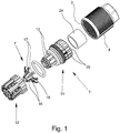
- the Fig. 1 shows a cable connection component 1 according to the invention for connecting a in the Fig. 2 and 7
- the cable 2 has a plurality of wires 21, a shielding 22 surrounding all cores 21 together and a cable jacket 23 surrounding the shielding 22.
- To the cable connection component 1 in particular include an internal thread 3 having a union nut 4, a plurality of incisions 5 having splice 6 of insulating material and a shielding element 7.
- Fig. 3 again splice part 6 shown from a cable receiving part 11 and a latchable with the cable receiving part 11 sleeve-shaped wire guide part 12.
- the cable receiving part 11 has a plurality of resilient latching arms 13 and the wire guide part 12 to the latching arms 13, inwardly, ie in the direction of the longitudinal axis of the wire guide part 12 facing latching hooks 14.
- shielding element 7 consists of an approximately annular central portion 15, a plurality of the central portion 15 in the direction of the wire guide member 12 side facing extending inner spring arms 16 and more from the central portion 15 in the direction of the wire guide member 12 side facing outer spring arms 17.
- the inner spring arms 16 are bent inwardly in the direction of the longitudinal axis of the cable connection component 1 in such a way that the ends of the inner spring arms contact the shield 22 of a connected cable 2.
- the outer spring arms 17 are bent from the annular central portion 15 to the outside, ie bent away from the longitudinal axis of the cable connection component 1.
- the outer spring arms 17 extend between the cable receiving part 11 and the wire guide part 12, so that the ends 18 of the outer spring arms 17 protrude outwardly from the splice part 6.
- the latching arms 13 are arranged concentrically to the longitudinal axis of the cable connection component 1 in the assembled state of the cable receiving part 11 and wire guide part 12 of a sleeve-shaped portion 19 of the wire guide part 12 facing the cable receiving part 11.
- the sleeve-shaped portion 19 of the wire guide part 12 encloses the latching arms 13 of the cable receiving part 11, an unintentional release of the latching connection between the cable receiving part 11 and the wire guide part 12 during insertion of the splice member 6 is prevented in the connector body 9.
- Fig. 3 shows the splice member 6 in the assembled state, wherein the annular central portion 15 of the Schirmungselements 7 disposed within the cable receiving part 11, namely surrounded by the latching arms 13.
- the outer spring arms 17 of the Schirmungselements 7 extend through the spaces 20 between the individual locking arms 13. It can be seen that both the inner spring arms 16 and the outer spring arms 17 are arranged evenly distributed on the circumference of the central portion 15, wherein the inner spring arms 16 are arranged offset to the outer spring arms 17 so that the inner spring arms 16 have the same angular position as the latching arms 13, so that in each case an inner spring arm 16 is covered by a corresponding latching arm 13.
- the width of the inner spring arms 16 is reduced from the central portion 15 towards its end, the ends being bent outwardly to facilitate the contacting of the shield 22 of the cable 2.
- the opening formed by the free ends of the inner spring arms 16 has a diameter which is slightly smaller than the outer diameter of the shield 22, so that upon insertion of a cable 2 through the Schirmungselement 7, the inner spring arms 16 are slightly deflected. As a result, a secure and good electrical contacting of the shield 22 is ensured by the ends of the inner spring arms 16.
- the width of the outer spring arms 17 increases from the central portion 15 to their ends 18, the ends 18 being approximately V-shaped in the illustrated embodiment. In this way, it is achieved that the ends 18 of the outer spring arms 17 projecting outward from the splicing part 6 make contact with the inner circumference of the metallic connecting body 9 at a plurality of points distributed over the circumference of the connecting body 9. At the same time, the splitting of the ends 18 of the outer spring arms 17 increases their elasticity, which likewise has a positive effect on the electrical connection between the ends 18 of the outer spring arms 17 and the inner surface of the metallic connection body 9.
- the cable connection component 1 still has an annular seal 24, which forms a Switzerlandentlastungs- and sealing area together with a plurality of annularly formed on the cable receiving part 11 fins 25.
- the slats 25 cooperate when screwing the union nut 4 with a provided on the inside of the union nut 4 bevel in the manner of a PG gland, so that when screwing the nut 4 on the connector body 9, the fins 25 are pressed against the seal 24, resulting in a seal and at the same time a strain relief of an inserted cable 2.
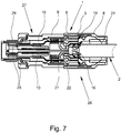
- the cable connection device 26 comprises a cable connection component 1 and a device connection component 27.
- the device connection component 27 has a metallic connection body 9 with an external thread 8 and a number of insulation displacement terminals 10 corresponding to the number of leads 21 to be connected and connection elements 28 connected in an electrically conductive manner to the insulation displacement terminals 10.
- the connection elements 28 are designed as pin contacts, which are each soldered or welded to the insulation displacement terminals 10.
- the device connection component 27 is formed as a connector.
- the connection body 9 has on the side facing away from the cable connection component 1 a second external thread 29, which is rotatable and thus can be screwed into a corresponding junction box.
- the latching arms 13 of the cable receiving part 11 are first widened, so that the shielding element 7 can be inserted with its middle section 15 between the latching arms 13.
- the outer spring arms 17 extend through the free spaces 20 between the latching arms 13, so that the ends 18 of the outer spring arms 17 protrude laterally from the cable receiving part 11. If the shielding element 7 is completely inserted between the latching arms 13 of the cable receiving part 11 and the expansion of the latching arms 13 is canceled, then the middle section 15 is clamped between the latching arms 13, so that the shielding element 7 is fixed radially in its position.
- the wire guide member 12 is fitted with its sleeve-shaped portion 19 on the cable receiving part 11, wherein the latching hooks 14 engage with the latching arms 13.
- the portions of the outer spring arms 17 projecting laterally from the cable receiving part 11 are pressed by the end face of the wire guide part 12 facing the cable receiving part 11 against a stop collar 30 formed on the cable receiving part 11, so that the shielding element 7 is also fixed axially in its position.
- the cable 2 is first introduced into the cable connection component 1 by the end of the cable 2 is pushed through the rear opening in the union nut 4 as far into the splice member 6, that the individual wire ends on the union nut 4 facing away from the splice 6 and the wire guide part 12 protrude. Subsequently, the individual wire ends are folded by about 90 ° to the outside and pressed into the formed in the wire guide part 12 recesses 31, which serve as restraint locks for the wire ends (see. Fig. 2 ).
- the shielding 22 of the cable 2 is automatically contacted by the ends of the inner spring arms 16, so that no additional steps are required for contacting the shielding 22 of the cable 2.
- the splice member 6 When screwing the union nut 4 on the external thread 8 of the metallic terminal body 9, the splice member 6 is inserted into the connector body 9, wherein the arranged in the connector body 9 insulation displacement plugs 10 in the core guide member 12 formed, dive open at the front incisions 5, whereby a reliable contact of the Incisions 5 crossing, outwardly folded wire ends is ensured by the insulation displacement terminals 10.
Description
Die Erfindung betrifft ein Kabelanschlussbauteil zum elektrisch Anschließen eines geschirmten mehradrigen Kabels, mit einer ein Innengewinde aufweisenden Überwurfmutter, mit einem mehrere Einschnitte aufweisenden Spleißteil aus isolierendem Material zur Vereinzelung der Adern des Kabels und mit einem Schirmungselement zur Kontaktierung der Schirmung des Kabels, wobei die Aderisolation der in das Spleißteil eingeführten Aderenden beim Aufschrauben der Überwurfmutter auf einen mit einem zum Innengewinde korrespondierenden Außengewinde versehenen elektrisch leitfähigen Anschlusskörper von im Anschlusskörper angeordneten und in die Einschnitte im Spleißteil eintauchenden Schneidklemmen durchtrennt und die Leiter der Adern kontaktiert werden.The invention relates to a cable connection component for electrically connecting a shielded multicore cable, having an internal thread having a union nut, with a multiple incisions splice piece of insulating material for singling the wires of the cable and with a shielding element for contacting the shield of the cable, wherein the core insulation of in the splice part introduced wire ends when screwing the nut on a provided with an internal thread corresponding to the external thread provided electrically conductive connection body arranged in the connection body and plunging into the incisions in the splice cutting terminals and contacts the conductors of the wires.
Außerdem betrifft die Erfindung noch eine Kabelanschlusseinrichtung sowie eine Kabelverbindungseinrichtung mit einem erfindungsgemäßen Kabelanschlussbauteil und einem Geräteanschlussbauteil bzw. einem Kabelverbindungsbauteil sowie ein Verfahren zur Montage eines Schirmungselements in einem Spleißteil eines erfindungsgemäßen Kabelanschlussbauteils.In addition, the invention also relates to a cable connection device and a cable connection device with a cable connection component according to the invention and a device connection component or a cable connection component and a method for mounting a shielding element in a splice part of a cable connection component according to the invention.
Aus der
Derartig aufgebaute Kabelanschluss- oder -verbindungseinrichtungen, welche grundsätzlich bereits aus
Auch aus der
In der industriellen Prozess- und Messtechnik wird häufig eine hohe Störfestigkeit gefordert. Sie ist in der Mess-, Steuer- und Regelungstechnik ein entscheidender Faktor für die Verfügbarkeit industrieller Anlagen. Beim Aufbau von störungsarmen System werden dabei zunehmend geschirmte Kabel verwendet, um kapazitive und induktive elektromagnetische Einkopplungen in das Kabel zu verhindern. Dabei ist das eine Ende des geschirmten Kabels häufig über einen Steckverbinder bzw. eine Kabelanschlusseinrichtung mit einem elektrischen Gerät, beispielsweise einer Sensor-Aktor-Box, und das andere Ende mit dem Versorgungsanschluss, beispielsweise über eine Reihenklemme, verbunden. Die Kontaktierung der Schirmung des Kabels erfolgt auf der Geräteseite zumeist über die metallische Hülse des Steckverbinders bzw. des Anschlusskörpers, über die die Schirmung mit dem metallischen Gehäuse des elektrischen Geräts verbunden wird.In industrial process and measurement technology, high immunity to interference is often required. It is a decisive factor in the availability of industrial plants in measurement and control technology. In the construction of low-noise system increasingly shielded cables are used to prevent capacitive and inductive electromagnetic couplings in the cable. In this case, one end of the shielded cable is often connected via a plug connector or a cable connection device to an electrical device, for example a sensor-actuator box, and the other end to the supply connection, for example via a terminal block. The contacting of the shield of the cable is done on the side of the device mostly via the metallic sleeve of the connector or the Connecting body, via which the shield is connected to the metallic housing of the electrical device.
Die
Aus der Praxis sind verschiedene Möglichkeiten bekannt, wie die elektrisch leitende Verbindung zwischen der Schirmung des Kabels und der metallischen Steckerhülse eines Steckverbinders, die dann als Schirmungshülse fungiert, hergestellt werden kann. Dabei kann die Schirmung entweder direkt oder über ein zusätzliches Schirmungselement mit der metallischen Steckerhülse verbunden werden. Aus der Praxis sind Steckverbinder bekannt, bei denen die Schirmung, die häufig als Schirmgeflecht ausgebildet ist, direkt mit der Steckerhülse verlötet wird. Diese Art der Verbindung der Schirmung mit der Steckerhülse erfordert jedoch einen relativ hohen Montageaufwand, wobei darüber hinaus der Lötprozess aufgrund der relativ hohen Masse der Steckerhülse relativ schwierig ist.From practice, various ways are known as the electrically conductive connection between the shield of the cable and the metallic plug sleeve of a connector, which then acts as Schirmungshülse, can be produced. In this case, the shield can be connected either directly or via an additional shielding element with the metallic plug sleeve. From practice connectors are known in which the shield, which is often designed as a shield braid, is soldered directly to the connector sleeve. However, this type of connection of the shield with the plug sleeve requires a relatively high installation cost, and moreover, the soldering process is relatively difficult due to the relatively high mass of the plug sleeve.
Bei einer alternativen Ausgestaltung der direkten Verbindung der Schirmung mit der Steckerhülse wird ein Teil des Kabelmantels am freien Ende des Kabels entfernt und die Schirmung über den angrenzenden Kabelmantel zurückgeschoben, bevor das so vorbereitete Kabel in die Steckerhülse eingeführt wird. Anschließend wird die Steckerhülse in dem Bereich, in dem die Schirmung über den Kabelmantel zurückgeschoben worden ist, soweit deformiert, dass die Schirmung zwischen dem Kabelmantel und der Steckerhülse eingeklemmt wird. Eine derartige direkte Verbindung der Schirmung des Kabels mit einer metallischen Steckerhülse ist bei der zuvor beschriebenen Kabelanschlusseinrichtung bzw. dem beschriebenen Kabelanschlussbauteil nicht ohne Weiteres möglich, weil das Kabel innerhalb des Kabelanschlussbauteils von dem aus isolierendem Material bestehenden Spleißteil umgeben ist.In an alternative embodiment of the direct connection of the shield to the connector sleeve, a portion of the cable jacket is removed at the free end of the cable and the shield is pushed back over the adjacent cable jacket before the cable thus prepared is inserted into the connector sleeve. Subsequently, the plug sleeve in the region in which the shield has been pushed back over the cable sheath, deformed so far that the shield between the cable sheath and the connector sleeve is clamped. Such a direct connection of the shield of the cable with a metallic plug sleeve is not without in the previously described cable connection device or the described cable connection component Further possible, because the cable is surrounded within the cable connection component of the existing of insulating material splice part.
Die
Aus der
Der Erfindung liegt daher die Aufgabe zugrunde, ein Kabelanschlussbauteil bzw. eine Kabelanschlusseinrichtung und eine Kabelverbindungsrichtung zur Verfügung zu stellen, die ein einfaches Anschließen eines geschirmten mehradrigen Kabels ermöglicht. Auf eine besondere Vorbereitung der Schirmung des Kabels soll dabei möglichst verzichtet werden.The invention is therefore based on the object to provide a cable connection component or a cable connection device and a cable connection direction, which is a simple connection of a shielded multicore Cable allows. On a special preparation of the shielding of the cable should be omitted as possible.
Diese Aufgabe bei dem eingangs beschriebenen Kabelanschlussbauteil mit den Merkmalen des Patentanspruchs 1 dadurch gelöst, dass das Spleißteil ein Kabelaufnahmeteil und ein Adernführungsteil aufweist, wobei das Kabelaufnahmeteil auf der dem Adernführungsteil zugewandten Seite mehrere Rastarme und das Adernführungsteil auf der dem Kabelaufnahmeteil zugewandten Seite mehrere zu den Rastarmen korrespondierende, nach innen ragende Rasthaken aufweist. Außerdem weist das Schirmungselement einen ringförmigen Mittelabschnitt, mehrere vom Mittelabschnitt in Richtung der dem Adernführungsteil zugewandten Seite sich erstreckende innere Federarme und mehrere vom Mittelabschnitt in Richtung der dem Adernführungsteil abgewandten Seite sich erstreckende äußere Federarme auf. Die inneren Federarme sind dabei derart in Richtung der Längsachse des Kabelanschlussbauteils nach innen abgebogen, dass ihre Enden die Schirmung eines angeschlossenen Kabels kontaktieren, während die äußeren Federarme derart von der Längsachse des Kabelanschlussbauteils weg nach außen abgebogen sind, dass sich die äußeren Federarme zwischen dem Kabelaufnahmeteil und dem Adernführungsteil erstrecken, wobei die Enden der äußeren Federarme aus dem Spleißteil herausragen.This object is achieved in the cable connection component described above with the features of
Wie bei dem aus der
Dadurch, dass das Spleißteil zweiteilig ausgebildet ist, nämlich aus einem Kabelaufnahmeteil und einem Adernführungsteil besteht, ist auf einfache Art und Weise die Möglichkeit geschaffen worden, die im Inneren des Spleißteils angeordnete Schirmung des Kabels über das Schirmungselement am Außenumfang des Spleißteils zu kontaktieren. Dadurch, dass das Schirmungselement mehrere äußere Federarme aufweist, erfolgt eine Anbindung der Schirmung an den metallischen Anschlusskörper an mehreren, über den Umfang verteilten Punkten, was für eine gute Schirmanbindung wünschenswert ist. Aufgrund der federnden Eigenschaft der inneren Federarme erfolgt dabei die Kontaktierung der Schirmung des Kabels automatisch beim Einführen des Kabels in das Kabelanschlussbauteil bzw. in das Kabelaufnahmeteil des Spleißteils, so dass eine besondere, zusätzliche Vorbereitung der Schirmung nicht erforderlich ist. Der Anschluss des geschirmten Kabels erfolgt vielmehr so, wie dies der Monteur vom Anschluss eines ungeschirmten Kabels an ein aus dem Stand der Technik bekanntes Kabelanschlussbauteil kennt.Characterized in that the splice part is formed in two parts, namely consists of a cable receiving part and a wire guide part, the possibility has been created in a simple manner to contact the arranged inside the splice part shielding of the cable via the shielding element on the outer circumference of the splice. Due to the fact that the shielding element has a plurality of outer spring arms, a connection of the shield to the metallic connector body at several distributed over the circumference points, which is desirable for a good shield connection. Due to the resilient property of the inner spring arms, the contacting of the shielding of the cable takes place automatically upon insertion of the cable into the cable connection component or into the cable receiving part of the splice part, so that a special, additional preparation of the shield is not required. The connection of the shielded cable is rather as the installer knows from the connection of an unshielded cable to a known from the prior art cable connection component.
Gemäß einer bevorzugten Ausgestaltung des Kabelanschlussbauteils sind die Rastarme des Kabelaufnahmeteils konzentrisch zur Längsachse des Kabelanschlussbauteils angeordnet, wobei im montierten Zustand von Kabelaufnahmeteil und Adernführungsteil ein dem Kabelanschlussbauteil zugewandter hülsenförmiger Bereich des Adernführungsteils die Rastarme umgibt. Der hülsenförmige Bereich des Adernführungsteils wird somit zur Verbindung mit dem Kabelaufnahmeteil einfach auf die Rastarme aufgesteckt, wobei die Rastarme mit den im Inneren des hülsenförmigen Bereichs angeordneten, korrespondierenden Rasthaken verrasten, so dass das Kabelaufnahmeteil und das Adernführungsteil sicher miteinander verbunden sind. Dadurch, dass der hülsenförmige Bereich des Adernführungsteils die Rastarme des Kabelaufnahmeteils im montierten Zustand umgibt, wird der Verbindungsbereich zwischen dem Kabelaufnahmeteil und dem Adernführungsteil mechanisch geschützt und darüber hinaus die Abdichtung der innerhalb der Rastarme des Kabelaufnahmeteils verlaufenden Adern des Kabels verbessert.According to a preferred embodiment of the cable connection component, the latching arms of the cable receiving part are arranged concentrically to the longitudinal axis of the cable connection component, wherein in the assembled state of cable receiving part and wire guide part facing the cable connection component sleeve-shaped portion of the wire guide part surrounding the latching arms. The sleeve-shaped region of the wire guide part is thus simply plugged onto the latching arms for connection to the cable receiving part, wherein the latching arms engage with the corresponding latching hooks arranged in the interior of the sleeve-shaped region, so that the cable receiving part and the wire guide part are securely connected to one another. Characterized in that the sleeve-shaped portion of the wire guide part surrounds the latching arms of the cable receiving part in the assembled state, the connection area between the cable receiving part and the wire guide part is mechanically protected and beyond the sealing of extending within the latching arms of the cable receiving part wires of the cable.
Wie zuvor ausgeführt worden ist, ist durch die zweiteilige Ausbildung des Spleißteils die Möglichkeit geschaffen worden, über das Schirmungselement die im Inneren des Spleißteils angeordnete Schirmung des anzuschließenden Kabels außerhalb des Spleißteils, nämlich durch den metallischen Anschlusskörper zu kontaktieren. Hierzu ist das Schirmungselement zwischen dem Kabelaufnahmeteil und dem Adernführungsteil angeordnet, wobei gemäß einer bevorzugten Ausgestaltung der Erfindung der ringförmige Mittelabschnitt des Schirmungselements, der die inneren Federarme mit den äußeren Federarmen verbindet, von den Rastarmen des Kabelaufnahmeteils umgeben ist, d.h. der ringförmige Mittelabschnitt ist innerhalb des Kabelaufnahmeteils angeordnet. Die äußeren Federarme des Schirmungselements erstrecken sich dabei durch die einzelnen Freiräume zwischen den Rastarmen des Kabelaufnahmeteils. Der ringförmige Mittelabschnitt und die Rastarme des Kabelaufnahmeteils sind dadurch beim Verrasten von Kabelaufnahmeteil und Adernführungsteil durch die Rastarme des Kabelaufnahmeteils vor Beschädigungen geschützt. Vorzugsweise sind dazu die inneren Federarme des Schirmungselements korrespondierend zu den Rastarmen des Kabelaufnahmeteils angeordnet, d. h. die inneren Federarme und die Rastarme weisen im montierten Zustand dieselbe Winkelposition auf.As has been stated above, the two-part design of the splice part has made it possible to contact via the shielding element the shielding of the cable to be connected outside the splicing part, namely the metallic connecting body, arranged in the interior of the splicing part. For this purpose, the shielding element between the cable receiving part and the wire guide part is arranged, wherein according to a preferred embodiment of the invention, the annular central portion of the Schirmungselements, which connects the inner spring arms with the outer spring arms, is surrounded by the latching arms of the cable receiving part, ie the annular central portion is disposed within the cable receiving portion. The outer spring arms of the Schirmungselements extend through the individual free spaces between the latching arms of the cable receiving part. The annular central portion and the latching arms of the cable receiving part are thereby protected during the locking of cable receiving part and wire guide part by the locking arms of the cable receiving part from damage. For this purpose, the inner spring arms of the shielding element are preferably arranged corresponding to the latching arms of the cable receiving part, ie the inner spring arms and the latching arms have the same angular position in the mounted state.
Gemäß einer weiteren vorteilhaften Ausgestaltung des erfindungsgemäßen Kabelanschlussbauteils sind außerdem die inneren Federarme und die äußeren Federarme gleichmäßig verteilt am Umfang des Mittelabschnitts angeordnet. Hierdurch wird sowohl eine gute elektrische Anbindung der Schirmung als auch eine einfache Herstellung des Schirmungselements, bei dem es sich vorzugsweise um ein Stanz-Biegeteil handelt, ermöglicht. Wenn, wie zuvor beschrieben, die inneren Federelemente korrespondierend zu den Rastarmen angeordnet sind, so sind die äußeren Federarme versetzt zu den inneren Federarmen angeordnet, da sich die äußeren Federarme durch die Freiräume zwischen den Rastarmen hindurch erstrecken.According to a further advantageous embodiment of the cable connection component according to the invention also the inner spring arms and the outer spring arms are arranged evenly distributed on the circumference of the central portion. As a result, both a good electrical connection of the shield and a simple production of the shielding element, which is preferably a stamped and bent part, made possible. If, as described above, the inner spring elements are arranged corresponding to the latching arms, the outer spring arms are arranged offset to the inner spring arms, since the outer spring arms extend through the spaces between the latching arms.
Neben dem zuvor beschriebenen Kabelanschlussbauteil betrifft die Erfindung auch noch eine Kabelanschlusseinrichtung zum elektrisch leitenden Anschließen eines geschirmten mehradrigen Kabels an ein elektrisches Gerät. Bei dem elektrischen Gerät kann es sich beispielsweise um eine Sensor-/Aktor-Box handeln. Unabhängig davon ist hier der Begriff "elektrisches Gerät" jedoch ganz allgemein zu verstehen, d. h. unter dem Begriff "elektrisches Gerät" sollen auch andere elektrische Bauteile, Einrichtungen und Vorrichtungen fallen.In addition to the cable connection component described above, the invention also relates to a cable connection device for the electrically conductive connection of a shielded multicore cable to an electrical device. The electrical device may be, for example, a sensor / actuator box. Regardless of this, however, the term "electrical device" is to be understood here in a general way, that is to say, "electrical device". H. The term "electrical device" is intended to include other electrical components, devices and devices.
Eine derartige Kabelanschlusseinrichtung weist neben dem zuvor beschriebenen Kabelanschlussbauteil noch ein Geräteanschlussbauteil auf, das einen metallischen Anschlusskörper mit einem zum Innengewinde der Überwurfmutter korrespondierenden Außengewinde aufweist. Außerdem sind in dem Anschlusskörper mehrere Schneidklemmen und mit den einzelnen Schneidklemmen verbundene Anschlusselemente vorgesehen, wobei die Schneidklemmen auf der dem Kabelanschlussbauteil zugewandten Seite und die Anschlusselemente auf der dem Kabelanschlussbauteil abgewandten Seite angeordnet sind. Häufig handelt es sich hierbei um einstückig ausgebildete Metallteile, die auf einer Seite als Schneidklemmen und auf der anderen Seite als Anschlusselemente ausgebildet sind. Die Anschlusselemente können vorzugsweise als Stift- oder Buchsenkontakte ausgebildet sein.Such a cable connection device has, in addition to the previously described cable connection component, a device connection component which has a metallic connection body with an external thread corresponding to the internal thread of the union nut. In addition, a plurality of insulation displacement terminals and connection elements connected to the individual insulation displacement terminals are provided in the connection body, wherein the insulation displacement terminals are arranged on the side facing the cable connection component side and the connection elements on the side facing away from the cable connection component side. Often these are integrally formed metal parts which are formed on one side as insulation displacement terminals and on the other side as connection elements. The connection elements may preferably be designed as pin or socket contacts.
Darüber hinaus betrifft die vorliegende Erfindung auch eine Kabelverbindungseinrichtung zum elektrisch leitenden Verbinden von zwei geschirmten mehradrigen Kabeln. Eine derartige Kabelverbindungseinrichtung, die häufig auch als Leitungsverbinder bezeichnet wird, weist neben dem erfindungsgemäßen Kabelanschlussbauteil noch ein Kabelverbindungsbauteil auf. Das Kabelverbindungsbauteil weist einen Anschlusskörper mit einem zum Innengewinde der Überwurfmutter korrespondierenden Außengewinde und mehrere im Anschlusskörper angeordnete Schneidklemmen und Anschlusselemente auf. Ebenso wie bei dem Geräteanschlussbauteil sind auch bei dem Kabelverbindungsbauteil die Schneidklemmen auf der dem Kabelanschlussbauteil zugewandten Seite und die Anschlusselemente auf der gegenüberliegenden Seite angeordnet, wobei die Schneidklemmen und die Anschlusselemente wiederum elektrische leitend miteinander verbunden sind. Für die Anschlusselemente des Kabelverbindungsbauteils, die zum Anschließen der Adern des zweiten Kabels dienen, können grundsätzlich die dem Fachmann bekannten Anschlusstechniken, beispielsweise Schraubanschluss oder Federkraftklemmanschluss, verwendet werden. Vorzugsweise sind jedoch auch die Anschlusselemente des Kabelverbindungsbauteils als Schneidklemmen ausgebildet, so dass in dem Anschlusskörper des Kabelverbindungsbauteils mehrere Metallteile angeordnet sind, die auf beiden Seiten als Schneidklemmen ausgebildet sind. Der Anschlusskörper weist dann ein zweites Außengewinde auf, auf dem die Überwurfmutter eines zweiten Kabelanschlussbauteils aufgeschraubt und damit ein Spleißteil in den Anschlusskörper eingeschoben werden kann.Moreover, the present invention also relates to a cable connection device for the electrically conductive connection of two shielded multicore cables. Such a cable connecting device, which is often referred to as a cable connector, in addition to the cable connection component according to the invention still has a cable connection component. The cable connection component has a connection body with an external thread corresponding to the internal thread of the union nut and a plurality of insulation displacement terminals and connection elements arranged in the connection body. As in the case of the device connection component, the insulation displacement terminals on the side facing the cable connection component and the connection elements on the opposite side are also arranged in the cable connection component, wherein the insulation displacement terminals and the connection elements are in turn electrically conductively connected to one another. For the connection elements of the cable connection component, which serve to connect the wires of the second cable, basically the connection techniques known to the person skilled in the art, for example screw connection or spring terminal connection, can be used. Preferably, however, the connection elements of the cable connection component are formed as insulation displacement terminals, so that in the connection body of the cable connection component a plurality of metal parts are arranged, which are formed on both sides as insulation displacement terminals. The connection body then has a second external thread, onto which the union nut of a second cable connection component can be screwed and thus a splice part can be inserted into the connection body.
Die Montage des Spleißteils mit dem Schirmungselement bzw. des Schirmungselements in dem Spleißteil erfolgt erfindungsgemäß gemäß den Merkmalen des Patentanspruchs 9. Das Verfahren weist dabei folgende wesentliche Schritte auf:
- Aufweiten der Rastarme des Kabelaufnahmeteils und Einführen des Schirmungselements zwischen die Rastarme des Kabelaufnahmeteils, wobei sich die äußeren Federarme des Schirmungselements durch die Freiräume zwischen den Rastarmen erstrecken;
- Aufstecken des Adernführungsteils auf das Kabelaufnahmeteil, so dass die Rastarme am Kabelaufnahmeteil mit den Rasthaken am Adernführungsteil verrasten.
- Widening the latching arms of the cable receiving part and inserting the shielding element between the latching arms of the cable receiving part, wherein the outer spring arms of the Schirmungselements extend through the free spaces between the latching arms;
- Attach the wire guide part on the cable receiving part, so that the latching arms engage the cable receiving part with the latching hooks on the wire guide part.
Bei dem erfindungsgemäßen Verfahren erfolgt dabei das Aufweiten der Rastarme des Kabelaufnahmeteils vorzugsweise mit Hilfe eines Domes, der von der dem Adernführungsteil abgewandten Seite in das Kabelaufnahmeteil eingesteckt wird. Ist das Schirmungselement zwischen die Rastarme des Kabelaufnahmeteils eingeführt, so wird der Dorn aus dem Kabelaufnahmeteil herausgezogen, so dass die Rastarme zurückfedern und dadurch das Schirmungselement in seiner Endposition radial fixieren. Durch das Aufstecken des Adernführungsteils auf das Kabelaufnahmeteil erfolgt sowohl die rastende Verbindung zwischen dem Adernführungsteil und dem Kabelaufnahmeteil, als auch die axiale Fixierung des Schirmungselement, da sich die freien Enden der äußeren Federarme zwischen der dem Kabelaufnahmeteil zugewandten Stirnseite des Adernführungsteils und einem entsprechend ausgebildeten Anschlagbund am Kabelaufnahmeteil nach außen, d. h. aus dem Spleißteil heraus, erstrecken.In the method according to the invention, the expansion of the latching arms of the cable receiving part is preferably carried out by means of a dome, which is inserted from the side facing away from the wire guide part in the cable receiving part. If the shielding element is inserted between the latching arms of the cable receiving part, then the mandrel is pulled out of the cable receiving part, so that the latching arms spring back and thereby radially fix the shielding element in its end position. By attaching the wire guide part on the cable receiving part takes place both the latching connection between the wire guide part and the cable receiving part, as well as the axial fixation of the Schirmungselement, as the free ends of the outer spring arms between the cable receiving part facing end side of the wire guide part and a trained stop collar on Cable receiving part to the outside, d. H. out of the splice part, extend.
Im Einzelnen gibt es nun eine Vielzahl von Möglichkeiten, das erfindungsgemäße Kabelanschlussbauteil sowie die Kabelanschlusseinrichtung und die Kabelverbindungseinrichtung auszugestalten und weiterzubilden. Dazu wird verwiesen sowohl auf die einzelnen Patentansprüche als auch auf die nachfolgende Beschreibung eines bevorzugten Ausführungsbeispiels in Verbindung mit der Zeichnung. In der Zeichnung zeigen
- Fig. 1
- eine perspektivische Explosionsdarstellung eines Kabelanschlussbauteils,
- Fig. 2
- ein Kabelanschlussbauteil mit einem angeschlossenen Kabel, teilweise geschnitten,
- Fig. 3
- einen Längsschnitt durch das Spleißteil des Kabelanschlussbauteils gemäß
Fig. 2 , mit montiertem Schirmungselement, - Fig. 4
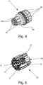
- eine perspektivische Darstellung eines separaten Kabelaufnahmeteils,
- Fig. 5
- eine perspektivische Darstellung eines separaten Adernführungsteils,
- Fig. 6
- eine perspektivische Darstellung eines Schirmungselements, und
- Fig. 7
- einen Längsschnitt durch eine Kabelanschlusseinrichtung mit einem Kabelanschlussbauteil und einem Geräteanschlussbauteil, mit angeschlossenem Kabel.
- Fig. 1
- an exploded perspective view of a cable connection component,
- Fig. 2
- a cable connection component with a connected cable, partially cut,
- Fig. 3
- a longitudinal section through the splice part of the cable connection component according to
Fig. 2 , with mounted shielding element, - Fig. 4
- a perspective view of a separate cable receiving part,
- Fig. 5
- a perspective view of a separate wire guide part,
- Fig. 6
- a perspective view of a Schirmungselements, and
- Fig. 7
- a longitudinal section through a cable connection device with a cable connection component and a device connection component, with attached cable.
Die
Wie aus der Explosionsdarstellung gemäß
Das in
Wie aus
Aus der vergrößerten Darstellung des Schirmungselements 7 gemäß
Während sich die Breite der inneren Federarme 16 zu ihrem Ende hin verringert, vergrößert sich die Breite der äußeren Federarme 17 vom Mittelabschnitt 15 zu ihren Enden 18, wobei die Enden 18 bei dem dargestellten Ausführungsbeispiel etwa V-förmig aufgespreitzt sind. Hierdurch wird erreicht, dass die aus dem Spleißteil 6 nach außen herausragenden Enden 18 der äußeren Federarme 17 den Innenumfang des metallischen Anschlusskörpers 9 an mehreren über den Umfang des Anschlusskörpers 9 verteilten Punkten kontaktiert. Gleichzeitig wird durch die Aufspaltung der Enden 18 der äußeren Federarme 17 deren Elastizität erhöht, was sich ebenfalls positiv auf die elektrische Verbindung zwischen den Enden 18 der äußeren Federarme 17 und der Innenfläche des metallischen Anschlusskörpers 9 auswirkt.As the width of the
Wie aus
Die in
Zur Montage des Spleißteils 6 mit dem Schirmungselements 7 werden zunächst die Rastarme 13 des Kabelaufnahmeteils 11 aufgeweitet, so dass das Schirmungselement 7 mit seinem Mittelabschnitt 15 zwischen die Rastarme 13 eingeschoben werden kann. Die äußeren Federarme 17 erstrecken sich dabei durch die Freiräume 20 zwischen den Rastarmen 13, so dass die Enden 18 der äußeren Federarme 17 aus dem Kabelaufnahmeteil 11 seitlich herausragen. Ist das Schirmungselement 7 vollständig zwischen die Rastarme 13 des Kabelaufnahmeteils 11 eingeschoben und die Aufweitung der Rastarme 13 aufgehoben, so wird der Mittelabschnitt 15 zwischen den Rastarmen 13 festgeklemmt, so dass das Schirmungselement 7 radial in seiner Position fixiert ist. Nun wird das Adernführungsteil 12 mit seinem hülsenförmigen Bereich 19 auf das Kabelaufnahmeteil 11 aufgesteckt, wobei die Rasthaken 14 mit den Rastarmen 13 verrasten. Gleichzeitige werden die aus dem Kabelaufnahmeteil 11 seitlich herausragenden Abschnitte der äußeren Federarme 17 von der dem Kabelaufnahmeteil 11 zugewandten Stirnseite des Adernführungsteils 12 gegen einem am Kabelaufnahmeteil 11 ausgebildeten Anschlagbund 30 gedrückt, so dass das Schirmungselement 7 auch axial in seiner Position fixiert ist.For mounting the
Zum elektrisch leitenden Anschließen eines geschirmten mehradrigen Kabels 2 wird zunächst das Kabel 2 in das Kabelanschlussbauteil 1 eingeführt, indem das Ende des Kabels 2 durch die rückwärtige Öffnung in der Überwurfmutter 4 soweit in das Spleißteil 6 eingeschoben wird, dass die einzelnen Aderenden auf der der Überwurfmutter 4 abgewandten Stirnseite aus dem Spleißteil 6 bzw. dem Adernführungsteil 12 herausragen. Anschließend werden die einzelnen Aderenden um etwas 90 ° nach außen umgelegt und in die im Adernführungsteil 12 ausgebildeten Ausnehmungen 31 eingedrückt, die als Rückhaltesperren für die Aderenden dienen (vgl.
Beim Aufschrauben der Überwurfmutter 4 auf das Außengewinde 8 des metallischen Anschlusskörpers 9 wird das Spleißteil 6 in den Anschlusskörper 9 eingeschoben, wobei die im Anschlusskörper 9 angeordneten Schneidklemmen 10 in die im Adernführungsteil 12 ausgebildeten, stirnseitig offenen Einschnitte 5 eintauchen, wodurch eine zuverlässige Kontaktierung der die Einschnitte 5 kreuzenden, nach außen umgelegten Aderenden durch die Schneidklemmen 10 gewährleistet ist. Gleichzeitig kommt es zu einer federnden Anlage der Enden 18 der äußeren Federarme 17 am Innenumfang des metallischen Anschlusskörpers 9, wodurch eine sichere elektrische Verbindung der Schirmung 22 über das Schirmungselement 7 zum metallischen Anschlusskörper 9 gegeben ist.When screwing the
Claims (10)
- Cable connection component for electrically connecting a shielded multi-core cable (2), comprising a union nut (4) having an internal thread (3), comprising a splice part (6) made of insulating material and having a plurality of notches (5) for separating the wires (21) of the cable (2), and comprising a shielding element (7) for contacting the shielding (22) of the cable (2),
wherein, when the union nut (4) is screwed onto an electrically conductive connecting body (9) provided with an external thread (8) corresponding to the internal thread (3), the wire insulation of the wire ends inserted into the splice part (6) is separated from insulation displacement terminals (10) arranged in the connecting body (9) and penetrating into the notches (5) in the splice part (6) and the conductors of the wires (21) are contacted,
wherein the splice part (6) has a cable-holder part (11) and a wire-guiding part (12), wherein the cable-holder part (11) has a plurality of latching arms (13) on the side facing the wire-guiding part (12), and the wire-guiding part (12) has a plurality of inwardly projecting latching catches (14) corresponding to the latching arms (13) on the side facing the cable-holder part (11),
wherein the shielding element (7) has an annular central section (15), a plurality of inner spring arms (16) extending from the central section (15) in the direction of the side facing the wire-guiding part (12), and a plurality of outer spring arms (17) extending from the central section (15) in the direction of the side located away from the wire-guiding part (12),
wherein the inner spring arms (16) are bent inwards in the direction of the longitudinal axis of the cable connection component (1) in such a way that the ends of the inner spring arms (16) contact the shielding (22) of a connected cable (2) and
wherein the outer spring arms (17) are bent outwards from the longitudinal axis of the cable connection component (1) in such a way that the outer spring arms (17) extend between the cable-holder part (11) and the wire-guiding part (12), such that the ends (18) of the outer spring arms (17) project out of the splice part (6). - Cable connection component according to claim 1, characterized in that the latching arms (13) are arranged concentrically with regard to the longitudinal axis of the cable connection component (1) and that in the mounted state of the cable-holder part (11) and the wire-guiding part (12), a sleeve-like area (19) of the wire-guiding part (12), facing the cable-holder part (11), surrounds the latching arms (13).
- Cable connection component according to claim 1 or 2, characterized in that the annular central section (15) of the shielding element (7) is surrounded by the latching arms (13) of the cable-holder part (11) and the outer spring arms (17) of the shielding element (7) extend through the clearances (20) between the latching arms (13).
- Cable connection component according to any one of claims 1 to 3, characterized in that the inner spring arms (16) and the outer spring arms (17) are arranged uniformly distributed on the circumference of the central section (15).
- Cable connection component according to any one of claims 1 to 4, characterized in that the width of the inner spring arms (16) decreases from the central section (15) towards their ends.
- Cable connection component according to any one of claims 1 to 5, characterized in that the width of the outer spring arms (17) increases from the central section (15) towards their ends (18), whereby the ends (18) are preferably V-shaped or U-shaped.
- Cable connection device for electrically conductive connection of a shielded multi-core cable (2) to an electrical device, with a device connection component (27) and with a cable connection component (1) according to any one of claims 1 to 6, wherein the device connection component (27) has a metallic connecting body (9) with an external thread (8), insulation displacement terminals (10) arranged in the connecting body (9), and connecting elements (28), wherein the connecting elements (28) and the insulation displacement terminals (10) are connected to each other electrically conductively.
- Cable link device for electrically conductive connection of two shielded multi-core cables, with a cable link component and a cable connection component (1) according to any one of claims 1 to 6, wherein the cable link component has a metallic connecting body with an external thread, insulation displacement terminals arranged in the connecting body, and connecting elements, whereby the connecting elements and the insulation displacement terminals are connected to each other electrically conductively.
- Method for assembling a shielding element (7) in a splice part (6) of a cable connection component (1) for electrically connecting a shielded multi-core cable (2),
comprising a splice part (6) made of insulating material and having a plurality of notches (5) for separating the wires (21) of the cable (2), and comprising a shielding element (7) for contacting the shielding (22) of the cable (2),
wherein, when the union nut (4) is screwed onto an electrically conductive connecting body (9) provided with an external thread (8) corresponding to the internal thread (3), the wire insulation of the wire ends inserted into the splice part (6) is separated from insulation displacement terminals (10) arranged in the connecting body (9) and penetrating into the notches (5) in the splice part (6) and the conductors of the wires (21) are contacted,
wherein the splice part (6) has a cable-holder part (11) and a wire-guiding part (12), wherein the cable-holder part (11) has a plurality of latching arms (13) on the side facing the wire-guiding part (12), and the wire-guiding part (12) has a plurality of inwardly projecting latching catches (14) corresponding to the latching arms (13) on the side facing the cable-holder part (11),
wherein the shielding element (7) has an annular central section (15), a plurality of inner spring arms (16) extending from the central section (15) in the direction of the side facing the wire-guiding part (12), and a series of outer spring arms (17) extending from the central section (15) in the direction of the side located away from the wire-guiding part (12),
wherein the inner spring arms (16) are bent inwards in the direction of the longitudinal axis of the cable connection component (1) in such a way that the ends of the inner spring arms (16) contact the shielding (22) of a connected cable (2) and
wherein the outer spring arms (17) are bent outwards from the longitudinal axis of the cable connection component (1) in such a way that the outer spring arms (17) extend between the cable-holder part (11) and the wire-guiding part (12), such that the ends (18) of the outer spring arms (17) project out of the splice part (6),
comprising the following steps:widening of the latching arms (13) of the cable-holder part (11) and insertion of the shielding element (7) between the latching arms (13) of the cable-holder part (11), whereby the other spring arms (17) of the shielding element (7) extend through the clearances (20) between the latching arms (13);fitting of the wire-guiding part (12) onto the cable-holder part (11), so that the latching arms (13) on the cable-holder part (11) catch with the latching catches (14) on the wire-guiding part (12). - Method according to claim 9, characterized in that a spike is inserted into the cable-holder part (11) from the side facing away from the wire-guiding part (12) to widen the latching arms (13).
Applications Claiming Priority (2)
| Application Number | Priority Date | Filing Date | Title |
|---|---|---|---|
| DE102014109040.3A DE102014109040B4 (en) | 2014-06-27 | 2014-06-27 | Cable connection component, cable connection device, cable connection device and mounting method |
| PCT/EP2015/064417 WO2015197773A1 (en) | 2014-06-27 | 2015-06-25 | Cable connection component |
Publications (2)
| Publication Number | Publication Date |
|---|---|
| EP3161908A1 EP3161908A1 (en) | 2017-05-03 |
| EP3161908B1 true EP3161908B1 (en) | 2018-06-06 |
Family
ID=53487370
Family Applications (1)
| Application Number | Title | Priority Date | Filing Date |
|---|---|---|---|
| EP15731354.5A Active EP3161908B1 (en) | 2014-06-27 | 2015-06-25 | Cable connection component |
Country Status (6)
| Country | Link |
|---|---|
| US (1) | US10056705B2 (en) |
| EP (1) | EP3161908B1 (en) |
| JP (1) | JP6261780B2 (en) |
| CN (1) | CN106663884B (en) |
| DE (1) | DE102014109040B4 (en) |
| WO (1) | WO2015197773A1 (en) |
Families Citing this family (6)
| Publication number | Priority date | Publication date | Assignee | Title |
|---|---|---|---|---|
| DE102015122471B4 (en) * | 2015-12-21 | 2017-09-07 | Amphenol-Tuchel Electronics Gmbh | Shielded connector assembly |
| DE102016003911B3 (en) * | 2016-03-31 | 2017-09-14 | Yamaichi Electronics Deutschland Gmbh | Circular connector and method for mounting a circular connector |
| CN106374252B (en) * | 2016-10-28 | 2019-02-15 | 河南天海电器有限公司 | A kind of multiconductor shielded connector |
| CN109149280B (en) * | 2017-06-28 | 2020-09-08 | 中航光电科技股份有限公司 | Cable assembly, connector assembly and connector accessory thereof |
| USD924143S1 (en) * | 2018-10-29 | 2021-07-06 | Phoenix Contact Gmbh & Co. Kg | Electrical connection plug |
| CN113595020B (en) * | 2021-08-03 | 2022-10-18 | 保定正开电缆附件有限公司 | Cable terminal fastening device |
Family Cites Families (14)
| Publication number | Priority date | Publication date | Assignee | Title |
|---|---|---|---|---|
| DE3734667C1 (en) * | 1987-10-13 | 1989-03-30 | Kathrein Werke Kg | Cable end plug |
| JPH08250230A (en) * | 1995-03-10 | 1996-09-27 | Yazaki Corp | Connector assembling method, and jig used in the method |
| DE29512585U1 (en) * | 1995-08-04 | 1995-11-30 | Phoenix Contact Gmbh & Co | Conductor connection element |
| DE19836622C2 (en) | 1998-08-13 | 2003-03-27 | Phoenix Contact Gmbh & Co | Cable connection or connection device |
| DE19951455C1 (en) | 1999-10-25 | 2001-10-25 | Phoenix Contact Gmbh & Co | Cable connection or connection device |
| DE10216483C1 (en) * | 2002-04-13 | 2003-11-20 | Harting Electric Gmbh & Co Kg | Circular connectors for shielded electrical cables |
| DE202008004892U1 (en) * | 2008-04-09 | 2008-06-12 | Harting Electric Gmbh & Co. Kg | Screen transfer element for plug connectors |
| WO2011053525A1 (en) * | 2009-10-26 | 2011-05-05 | Heyco, Inc. | Electrical connectors for photovoltaic systems |
| DE102010017265B4 (en) * | 2010-06-07 | 2012-03-01 | Phoenix Contact Gmbh & Co. Kg | A cable termination device and method for connecting a cable to a cable termination device |
| DE102010017266C5 (en) * | 2010-06-07 | 2015-01-08 | Phoenix Contact Gmbh & Co. Kg | Electrical distribution device |
| DE102011108123B4 (en) * | 2011-07-21 | 2013-02-28 | Phoenix Contact Gmbh & Co. Kg | Cable connection component and cable connection device and cable connection device with a cable connection component |
| DE102011056715A1 (en) * | 2011-12-20 | 2013-06-20 | Telegärtner Karl Gärtner GmbH | Cable connecting device |
| DE102012103708B3 (en) * | 2012-04-27 | 2013-07-11 | HARTING Electronics GmbH | Insulator of a connector |
| GB2536844B (en) * | 2014-01-31 | 2020-06-10 | Ideal Ind | Plug connector |
-
2014
- 2014-06-27 DE DE102014109040.3A patent/DE102014109040B4/en not_active Expired - Fee Related
-
2015
- 2015-06-25 CN CN201580034979.7A patent/CN106663884B/en active Active
- 2015-06-25 EP EP15731354.5A patent/EP3161908B1/en active Active
- 2015-06-25 WO PCT/EP2015/064417 patent/WO2015197773A1/en active Application Filing
- 2015-06-25 US US15/322,228 patent/US10056705B2/en active Active
- 2015-06-25 JP JP2016575389A patent/JP6261780B2/en active Active
Non-Patent Citations (1)
| Title |
|---|
| None * |
Also Published As
| Publication number | Publication date |
|---|---|
| CN106663884B (en) | 2019-03-15 |
| JP6261780B2 (en) | 2018-01-17 |
| CN106663884A (en) | 2017-05-10 |
| DE102014109040B4 (en) | 2016-03-10 |
| WO2015197773A1 (en) | 2015-12-30 |
| EP3161908A1 (en) | 2017-05-03 |
| US10056705B2 (en) | 2018-08-21 |
| JP2017523569A (en) | 2017-08-17 |
| US20170133773A1 (en) | 2017-05-11 |
| DE102014109040A1 (en) | 2015-12-31 |
Similar Documents
| Publication | Publication Date | Title |
|---|---|---|
| EP3161908B1 (en) | Cable connection component | |
| EP2577806B1 (en) | Cable connection system and method for connecting a cable to a cable connection system | |
| DE112018001914B4 (en) | Inner conductor connection and shielded connector | |
| EP3161907A1 (en) | Cable connection component | |
| DE102011108123B4 (en) | Cable connection component and cable connection device and cable connection device with a cable connection component | |
| EP2731201B1 (en) | Electrical connector and method for assembling parts of an electrical connector | |
| EP3261109B1 (en) | Fuse device | |
| EP2993736B1 (en) | Electronic component | |
| DE102014116482B4 (en) | Contact element | |
| EP3539183B1 (en) | Contact element comprising a clamping terminal for a stranded conductor | |
| DE102013001828B4 (en) | Shielding element and connector and a method for connecting a cable having a shielding to a connector by means of the Schirmungselements | |
| DE19717216A1 (en) | Process for stripping-free contacting of multi-core round cables and contacting devices therefor | |
| EP3140883B1 (en) | Contact element | |
| DE102017222809A1 (en) | Electrical connector and connector | |
| WO2021139986A1 (en) | Strain relief for a plug connector arranged on a shielded line | |
| DE19525801C2 (en) | Device for the electrically conductive connection of two electrical lines | |
| DE202019101871U1 (en) | Contact element with seal for a plug connection | |
| DE102010008845A1 (en) | Cable connection component for electrical conductive connection of e.g. multi-core round cable, has wire receiving and guiding part into which cable ends are inserted so that insulation of piece is separated and made to contact piece | |
| DE102017126757B4 (en) | Electrical connector | |
| DE102014005918A1 (en) | Cable connector for the axial connection of cables | |
| DE202016106269U1 (en) | Contact element with a clamping connection for stranded conductors | |
| EP3707780B1 (en) | Contact element comprising a clamping terminal for a stranded conductor | |
| EP0903809A2 (en) | Anchoring device and connecting device using it | |
| DE202017107625U1 (en) | Electrical connector |
Legal Events
| Date | Code | Title | Description |
|---|---|---|---|
| STAA | Information on the status of an ep patent application or granted ep patent |
Free format text: STATUS: THE INTERNATIONAL PUBLICATION HAS BEEN MADE |
|
| PUAI | Public reference made under article 153(3) epc to a published international application that has entered the european phase |
Free format text: ORIGINAL CODE: 0009012 |
|
| STAA | Information on the status of an ep patent application or granted ep patent |
Free format text: STATUS: REQUEST FOR EXAMINATION WAS MADE |
|
| 17P | Request for examination filed |
Effective date: 20161223 |
|
| AK | Designated contracting states |
Kind code of ref document: A1 Designated state(s): AL AT BE BG CH CY CZ DE DK EE ES FI FR GB GR HR HU IE IS IT LI LT LU LV MC MK MT NL NO PL PT RO RS SE SI SK SM TR |
|
| AX | Request for extension of the european patent |
Extension state: BA ME |
|
| DAV | Request for validation of the european patent (deleted) | ||
| DAX | Request for extension of the european patent (deleted) | ||
| RIC1 | Information provided on ipc code assigned before grant |
Ipc: H01R 13/512 20060101ALI20171023BHEP Ipc: H01R 13/59 20060101ALN20171023BHEP Ipc: H01R 9/05 20060101AFI20171023BHEP Ipc: H01R 13/58 20060101ALN20171023BHEP Ipc: H01R 13/52 20060101ALN20171023BHEP Ipc: H01R 4/24 20060101ALI20171023BHEP Ipc: H01R 43/20 20060101ALI20171023BHEP |
|
| GRAP | Despatch of communication of intention to grant a patent |
Free format text: ORIGINAL CODE: EPIDOSNIGR1 |
|
| STAA | Information on the status of an ep patent application or granted ep patent |
Free format text: STATUS: GRANT OF PATENT IS INTENDED |
|
| RIC1 | Information provided on ipc code assigned before grant |
Ipc: H01R 43/20 20060101ALI20171116BHEP Ipc: H01R 9/05 20060101AFI20171116BHEP Ipc: H01R 13/59 20060101ALN20171116BHEP Ipc: H01R 4/24 20060101ALI20171116BHEP Ipc: H01R 13/58 20060101ALN20171116BHEP Ipc: H01R 13/52 20060101ALN20171116BHEP Ipc: H01R 13/512 20060101ALI20171116BHEP |
|
| INTG | Intention to grant announced |
Effective date: 20171204 |
|
| GRAS | Grant fee paid |
Free format text: ORIGINAL CODE: EPIDOSNIGR3 |
|
| GRAA | (expected) grant |
Free format text: ORIGINAL CODE: 0009210 |
|
| STAA | Information on the status of an ep patent application or granted ep patent |
Free format text: STATUS: THE PATENT HAS BEEN GRANTED |
|
| AK | Designated contracting states |
Kind code of ref document: B1 Designated state(s): AL AT BE BG CH CY CZ DE DK EE ES FI FR GB GR HR HU IE IS IT LI LT LU LV MC MK MT NL NO PL PT RO RS SE SI SK SM TR |
|
| REG | Reference to a national code |
Ref country code: GB Ref legal event code: FG4D Free format text: NOT ENGLISH |
|
| REG | Reference to a national code |
Ref country code: CH Ref legal event code: EP Ref country code: AT Ref legal event code: REF Ref document number: 1007071 Country of ref document: AT Kind code of ref document: T Effective date: 20180615 |
|
| REG | Reference to a national code |
Ref country code: IE Ref legal event code: FG4D Free format text: LANGUAGE OF EP DOCUMENT: GERMAN |
|
| REG | Reference to a national code |
Ref country code: FR Ref legal event code: PLFP Year of fee payment: 4 |
|
| REG | Reference to a national code |
Ref country code: DE Ref legal event code: R096 Ref document number: 502015004567 Country of ref document: DE |
|
| REG | Reference to a national code |
Ref country code: NL Ref legal event code: MP Effective date: 20180606 |
|
| REG | Reference to a national code |
Ref country code: LT Ref legal event code: MG4D |
|
| PG25 | Lapsed in a contracting state [announced via postgrant information from national office to epo] |
Ref country code: ES Free format text: LAPSE BECAUSE OF FAILURE TO SUBMIT A TRANSLATION OF THE DESCRIPTION OR TO PAY THE FEE WITHIN THE PRESCRIBED TIME-LIMIT Effective date: 20180606 Ref country code: SE Free format text: LAPSE BECAUSE OF FAILURE TO SUBMIT A TRANSLATION OF THE DESCRIPTION OR TO PAY THE FEE WITHIN THE PRESCRIBED TIME-LIMIT Effective date: 20180606 Ref country code: LT Free format text: LAPSE BECAUSE OF FAILURE TO SUBMIT A TRANSLATION OF THE DESCRIPTION OR TO PAY THE FEE WITHIN THE PRESCRIBED TIME-LIMIT Effective date: 20180606 Ref country code: BG Free format text: LAPSE BECAUSE OF FAILURE TO SUBMIT A TRANSLATION OF THE DESCRIPTION OR TO PAY THE FEE WITHIN THE PRESCRIBED TIME-LIMIT Effective date: 20180906 Ref country code: FI Free format text: LAPSE BECAUSE OF FAILURE TO SUBMIT A TRANSLATION OF THE DESCRIPTION OR TO PAY THE FEE WITHIN THE PRESCRIBED TIME-LIMIT Effective date: 20180606 Ref country code: NO Free format text: LAPSE BECAUSE OF FAILURE TO SUBMIT A TRANSLATION OF THE DESCRIPTION OR TO PAY THE FEE WITHIN THE PRESCRIBED TIME-LIMIT Effective date: 20180906 Ref country code: CY Free format text: LAPSE BECAUSE OF FAILURE TO SUBMIT A TRANSLATION OF THE DESCRIPTION OR TO PAY THE FEE WITHIN THE PRESCRIBED TIME-LIMIT Effective date: 20180606 |
|
| PG25 | Lapsed in a contracting state [announced via postgrant information from national office to epo] |
Ref country code: RS Free format text: LAPSE BECAUSE OF FAILURE TO SUBMIT A TRANSLATION OF THE DESCRIPTION OR TO PAY THE FEE WITHIN THE PRESCRIBED TIME-LIMIT Effective date: 20180606 Ref country code: LV Free format text: LAPSE BECAUSE OF FAILURE TO SUBMIT A TRANSLATION OF THE DESCRIPTION OR TO PAY THE FEE WITHIN THE PRESCRIBED TIME-LIMIT Effective date: 20180606 Ref country code: HR Free format text: LAPSE BECAUSE OF FAILURE TO SUBMIT A TRANSLATION OF THE DESCRIPTION OR TO PAY THE FEE WITHIN THE PRESCRIBED TIME-LIMIT Effective date: 20180606 Ref country code: GR Free format text: LAPSE BECAUSE OF FAILURE TO SUBMIT A TRANSLATION OF THE DESCRIPTION OR TO PAY THE FEE WITHIN THE PRESCRIBED TIME-LIMIT Effective date: 20180907 |
|
| PG25 | Lapsed in a contracting state [announced via postgrant information from national office to epo] |
Ref country code: NL Free format text: LAPSE BECAUSE OF FAILURE TO SUBMIT A TRANSLATION OF THE DESCRIPTION OR TO PAY THE FEE WITHIN THE PRESCRIBED TIME-LIMIT Effective date: 20180606 |
|
| PG25 | Lapsed in a contracting state [announced via postgrant information from national office to epo] |
Ref country code: SK Free format text: LAPSE BECAUSE OF FAILURE TO SUBMIT A TRANSLATION OF THE DESCRIPTION OR TO PAY THE FEE WITHIN THE PRESCRIBED TIME-LIMIT Effective date: 20180606 Ref country code: IS Free format text: LAPSE BECAUSE OF FAILURE TO SUBMIT A TRANSLATION OF THE DESCRIPTION OR TO PAY THE FEE WITHIN THE PRESCRIBED TIME-LIMIT Effective date: 20181006 Ref country code: PL Free format text: LAPSE BECAUSE OF FAILURE TO SUBMIT A TRANSLATION OF THE DESCRIPTION OR TO PAY THE FEE WITHIN THE PRESCRIBED TIME-LIMIT Effective date: 20180606 Ref country code: EE Free format text: LAPSE BECAUSE OF FAILURE TO SUBMIT A TRANSLATION OF THE DESCRIPTION OR TO PAY THE FEE WITHIN THE PRESCRIBED TIME-LIMIT Effective date: 20180606 Ref country code: RO Free format text: LAPSE BECAUSE OF FAILURE TO SUBMIT A TRANSLATION OF THE DESCRIPTION OR TO PAY THE FEE WITHIN THE PRESCRIBED TIME-LIMIT Effective date: 20180606 Ref country code: CZ Free format text: LAPSE BECAUSE OF FAILURE TO SUBMIT A TRANSLATION OF THE DESCRIPTION OR TO PAY THE FEE WITHIN THE PRESCRIBED TIME-LIMIT Effective date: 20180606 |
|
| REG | Reference to a national code |
Ref country code: CH Ref legal event code: PL |
|
| PG25 | Lapsed in a contracting state [announced via postgrant information from national office to epo] |
Ref country code: SM Free format text: LAPSE BECAUSE OF FAILURE TO SUBMIT A TRANSLATION OF THE DESCRIPTION OR TO PAY THE FEE WITHIN THE PRESCRIBED TIME-LIMIT Effective date: 20180606 |
|
| REG | Reference to a national code |
Ref country code: BE Ref legal event code: MM Effective date: 20180630 |
|
| REG | Reference to a national code |
Ref country code: DE Ref legal event code: R097 Ref document number: 502015004567 Country of ref document: DE |
|
| REG | Reference to a national code |
Ref country code: IE Ref legal event code: MM4A |
|
| PG25 | Lapsed in a contracting state [announced via postgrant information from national office to epo] |
Ref country code: LU Free format text: LAPSE BECAUSE OF NON-PAYMENT OF DUE FEES Effective date: 20180625 Ref country code: MC Free format text: LAPSE BECAUSE OF FAILURE TO SUBMIT A TRANSLATION OF THE DESCRIPTION OR TO PAY THE FEE WITHIN THE PRESCRIBED TIME-LIMIT Effective date: 20180606 |
|
| PLBE | No opposition filed within time limit |
Free format text: ORIGINAL CODE: 0009261 |
|
| STAA | Information on the status of an ep patent application or granted ep patent |
Free format text: STATUS: NO OPPOSITION FILED WITHIN TIME LIMIT |
|
| PG25 | Lapsed in a contracting state [announced via postgrant information from national office to epo] |
Ref country code: IE Free format text: LAPSE BECAUSE OF NON-PAYMENT OF DUE FEES Effective date: 20180625 Ref country code: CH Free format text: LAPSE BECAUSE OF NON-PAYMENT OF DUE FEES Effective date: 20180630 Ref country code: LI Free format text: LAPSE BECAUSE OF NON-PAYMENT OF DUE FEES Effective date: 20180630 |
|
| 26N | No opposition filed |
Effective date: 20190307 |
|
| PG25 | Lapsed in a contracting state [announced via postgrant information from national office to epo] |
Ref country code: DK Free format text: LAPSE BECAUSE OF FAILURE TO SUBMIT A TRANSLATION OF THE DESCRIPTION OR TO PAY THE FEE WITHIN THE PRESCRIBED TIME-LIMIT Effective date: 20180606 Ref country code: BE Free format text: LAPSE BECAUSE OF NON-PAYMENT OF DUE FEES Effective date: 20180630 Ref country code: SI Free format text: LAPSE BECAUSE OF FAILURE TO SUBMIT A TRANSLATION OF THE DESCRIPTION OR TO PAY THE FEE WITHIN THE PRESCRIBED TIME-LIMIT Effective date: 20180606 |
|
| PG25 | Lapsed in a contracting state [announced via postgrant information from national office to epo] |
Ref country code: AL Free format text: LAPSE BECAUSE OF FAILURE TO SUBMIT A TRANSLATION OF THE DESCRIPTION OR TO PAY THE FEE WITHIN THE PRESCRIBED TIME-LIMIT Effective date: 20180606 |
|
| PG25 | Lapsed in a contracting state [announced via postgrant information from national office to epo] |
Ref country code: MT Free format text: LAPSE BECAUSE OF FAILURE TO SUBMIT A TRANSLATION OF THE DESCRIPTION OR TO PAY THE FEE WITHIN THE PRESCRIBED TIME-LIMIT Effective date: 20180606 |
|
| GBPC | Gb: european patent ceased through non-payment of renewal fee |
Effective date: 20190625 |
|
| PG25 | Lapsed in a contracting state [announced via postgrant information from national office to epo] |
Ref country code: TR Free format text: LAPSE BECAUSE OF FAILURE TO SUBMIT A TRANSLATION OF THE DESCRIPTION OR TO PAY THE FEE WITHIN THE PRESCRIBED TIME-LIMIT Effective date: 20180606 |
|
| PG25 | Lapsed in a contracting state [announced via postgrant information from national office to epo] |
Ref country code: GB Free format text: LAPSE BECAUSE OF NON-PAYMENT OF DUE FEES Effective date: 20190625 |
|
| PG25 | Lapsed in a contracting state [announced via postgrant information from national office to epo] |
Ref country code: PT Free format text: LAPSE BECAUSE OF FAILURE TO SUBMIT A TRANSLATION OF THE DESCRIPTION OR TO PAY THE FEE WITHIN THE PRESCRIBED TIME-LIMIT Effective date: 20180606 |
|
| PG25 | Lapsed in a contracting state [announced via postgrant information from national office to epo] |
Ref country code: MK Free format text: LAPSE BECAUSE OF NON-PAYMENT OF DUE FEES Effective date: 20180606 Ref country code: HU Free format text: LAPSE BECAUSE OF FAILURE TO SUBMIT A TRANSLATION OF THE DESCRIPTION OR TO PAY THE FEE WITHIN THE PRESCRIBED TIME-LIMIT; INVALID AB INITIO Effective date: 20150625 |
|
| REG | Reference to a national code |
Ref country code: AT Ref legal event code: MM01 Ref document number: 1007071 Country of ref document: AT Kind code of ref document: T Effective date: 20200625 |
|
| PG25 | Lapsed in a contracting state [announced via postgrant information from national office to epo] |
Ref country code: AT Free format text: LAPSE BECAUSE OF NON-PAYMENT OF DUE FEES Effective date: 20200625 |
|
| P01 | Opt-out of the competence of the unified patent court (upc) registered |
Effective date: 20230424 |
|
| PGFP | Annual fee paid to national office [announced via postgrant information from national office to epo] |
Ref country code: FR Payment date: 20230622 Year of fee payment: 9 |
|
| PGFP | Annual fee paid to national office [announced via postgrant information from national office to epo] |
Ref country code: IT Payment date: 20230620 Year of fee payment: 9 |
|
| PGFP | Annual fee paid to national office [announced via postgrant information from national office to epo] |
Ref country code: DE Payment date: 20230828 Year of fee payment: 9 |