EP3161501B1 - Bore region lighting unit for magnetic resonance scanner - Google Patents
Bore region lighting unit for magnetic resonance scanner Download PDFInfo
- Publication number
- EP3161501B1 EP3161501B1 EP15728900.0A EP15728900A EP3161501B1 EP 3161501 B1 EP3161501 B1 EP 3161501B1 EP 15728900 A EP15728900 A EP 15728900A EP 3161501 B1 EP3161501 B1 EP 3161501B1
- Authority
- EP
- European Patent Office
- Prior art keywords
- bore
- lighting
- center axis
- cover
- front cover
- Prior art date
- Legal status (The legal status is an assumption and is not a legal conclusion. Google has not performed a legal analysis and makes no representation as to the accuracy of the status listed.)
- Active
Links
Images


Classifications
-
- F—MECHANICAL ENGINEERING; LIGHTING; HEATING; WEAPONS; BLASTING
- F21—LIGHTING
- F21V—FUNCTIONAL FEATURES OR DETAILS OF LIGHTING DEVICES OR SYSTEMS THEREOF; STRUCTURAL COMBINATIONS OF LIGHTING DEVICES WITH OTHER ARTICLES, NOT OTHERWISE PROVIDED FOR
- F21V3/00—Globes; Bowls; Cover glasses
-
- F—MECHANICAL ENGINEERING; LIGHTING; HEATING; WEAPONS; BLASTING
- F21—LIGHTING
- F21V—FUNCTIONAL FEATURES OR DETAILS OF LIGHTING DEVICES OR SYSTEMS THEREOF; STRUCTURAL COMBINATIONS OF LIGHTING DEVICES WITH OTHER ARTICLES, NOT OTHERWISE PROVIDED FOR
- F21V33/00—Structural combinations of lighting devices with other articles, not otherwise provided for
- F21V33/0064—Health, life-saving or fire-fighting equipment
- F21V33/0068—Medical equipment
-
- G—PHYSICS
- G01—MEASURING; TESTING
- G01R—MEASURING ELECTRIC VARIABLES; MEASURING MAGNETIC VARIABLES
- G01R33/00—Arrangements or instruments for measuring magnetic variables
- G01R33/20—Arrangements or instruments for measuring magnetic variables involving magnetic resonance
- G01R33/28—Details of apparatus provided for in groups G01R33/44 - G01R33/64
-
- G—PHYSICS
- G01—MEASURING; TESTING
- G01R—MEASURING ELECTRIC VARIABLES; MEASURING MAGNETIC VARIABLES
- G01R33/00—Arrangements or instruments for measuring magnetic variables
- G01R33/20—Arrangements or instruments for measuring magnetic variables involving magnetic resonance
- G01R33/44—Arrangements or instruments for measuring magnetic variables involving magnetic resonance using nuclear magnetic resonance [NMR]
- G01R33/48—NMR imaging systems
- G01R33/54—Signal processing systems, e.g. using pulse sequences ; Generation or control of pulse sequences; Operator console
- G01R33/546—Interface between the MR system and the user, e.g. for controlling the operation of the MR system or for the design of pulse sequences
-
- F—MECHANICAL ENGINEERING; LIGHTING; HEATING; WEAPONS; BLASTING
- F21—LIGHTING
- F21W—INDEXING SCHEME ASSOCIATED WITH SUBCLASSES F21K, F21L, F21S and F21V, RELATING TO USES OR APPLICATIONS OF LIGHTING DEVICES OR SYSTEMS
- F21W2131/00—Use or application of lighting devices or systems not provided for in codes F21W2102/00-F21W2121/00
- F21W2131/20—Lighting for medical use
-
- G—PHYSICS
- G01—MEASURING; TESTING
- G01R—MEASURING ELECTRIC VARIABLES; MEASURING MAGNETIC VARIABLES
- G01R33/00—Arrangements or instruments for measuring magnetic variables
- G01R33/20—Arrangements or instruments for measuring magnetic variables involving magnetic resonance
- G01R33/28—Details of apparatus provided for in groups G01R33/44 - G01R33/64
- G01R33/288—Provisions within MR facilities for enhancing safety during MR, e.g. reduction of the specific absorption rate [SAR], detection of ferromagnetic objects in the scanner room
Definitions
- the invention pertains to a magnetic resonance imaging system having a magnet bore and a bore region lighting unit, and to a bore region lighting unit for use in a magnetic resonance imaging system.
- Illumination assemblies for lighting the magnet bore for enhancing patient comfort are known, for instance, from patent US 4,613,926 , wherein plastic fiber optic bundles with ends in frosted tubes are arranged in the magnet bore behind a deflector element to uniformly diffuse light provided by the plastic fiber optic bundles.
- Japanese patent application JP 2013 163018 A describes a magnetic resonance imaging device that includes a gantry unit, front light sources, and an outer casing for the gantry unit.
- the gantry unit has a bore serving as a space where a magnetic resonance image is to be captured, and is configured to collect magnetic resonance signals from a subject placed on a patient bed top in a state in which the subject has been moved into the bore by a bed unit for moving the patient bed top.
- the front light sources are installed around a front opening that is an opening of the bore and is located in front of the bed unit.
- the outer casing of the gantry unit, a portion of which is illuminated with light applied from the front light sources, is made of a transparent or translucent material.
- the front light sources By providing the front light sources, it is possible to make the portion of the cover positioned near the front opening brighter than the surroundings thereof. Because the portion of the cover positioned near the front opening is illuminated, the subject feels that the front opening is large, while the subject is moved into the bore.
- International application WO 2014/029571 A describes a medical device with a tubular interior space for accommodating a subject to be examined, a cladding of the tubular interior space facing towards the subject to be examined and a device for lighting the tubular interior space, which comprises at least one lamp, wherein the lamp is mounted on the side of the cladding of the tubular interior space facing towards the subject to be examined and forms the tunnel contour of the tubular interior space.
- the object is achieved a magnetic resonance imaging system configured for acquiring magnetic resonance images of at least a portion of a subject of interest, comprising:
- Lighting members of the bore region lighting unit arranged at the front cover are configured, in at least one state of operation, for generating lighting conditions at the front cover.
- the area-averaged brightness-related photometric parameter decreases in a radial direction towards the center axis at least for the continuous range of the azimuth angle about the center axis and each annular region covers a number of lighting members arranged at the front cover.
- the bore region lighting unit includes a bore cover lighting unit comprising lighting members arranged at the bore cover that is configured, in at least one state of operation, for generating lighting conditions at the bore cover.
- the area-averaged brightness-related photometric parameter increases in the radial direction towards the center axis at least for the continuous range of the azimuth angle about the center axis if the bore cover is at least partially illuminated by the bore cover lighting unit.
- Each annular region covers a number of lighting members arranged at the bore cover.
- the area-averaged brightness-related photometric parameter increases, at locations in the azimuthally arranged annular regions of the virtual plane, in the radial direction towards the center axis at least for the continuous range of the azimuth angle about the center axis.
- bore region shall be understood particularly to encompass the bore, the bore cover and a portion of the front cover which is adjacent to the opening and a proximal end of the bore.
- a width of the portion of the front cover shall preferably be wider than 20%, more preferable wider than 30% and, most preferable, more than 50% of the total width of the front cover.
- lighting members shall be understood particularly to encompass bulb-type light sources, optical fiber ends and lightemitting diodes (LEDs).
- the continuous range of the azimuth angle about the center axis is preferably between ⁇ /2 and 2 ⁇ and more preferably between ⁇ and 2 ⁇ .
- the dimension of the bore region is either not in the focus of the subject of interest's attention anymore, or the dimension of the bore region appears to be larger in the perception of the subject of interest.
- Lighting conditions suitable for detracting the subject of interest's attention or for influencing the subject of interest's optical perception regarding the dimension of the magnet bore can readily be generated.
- the subject of interest can be positioned within the examination space in a more relaxed condition, and an improved cooperation of the subject of interest can be accomplished as an important pre-requisite for an undisturbed acquisition of magnetic resonance images.
- influencing the subject of interest's optical perception is of special importance prior to being positioned within the examination space.
- lighting members which are configured for generating lighting conditions at a bore region such that a spatially gradually varying distribution of an area-averaged brightness-related photometric parameter is generated on an interface between the front cover and bore cover for at least a continuous range of an azimuth angle about the center axis when at least part of the lighting members are switched on, optical sharp edges between darker and lighter regions can be decreased or avoided on the interface between the front cover and bore cover.
- This will optically enlarge the radial dimension of the bore, which in turn may decrease anxiety in the subject of interest.
- the light distribution extends over a width of the portion of the front wider than 20%, more preferable wider than 30% and, most preferable, more than 50% of the total width of the front cover.
- This effect of optically enlarging the bore could for example be achieved by gradually decreasing the area-averaged brightness-related photometric parameter in a radial direction towards the center axis when there is no bore lighting or dimmed lighting in the bore.
- This effect could for example also be achieved by both lighting (part of) the bore and (portion of) the front cover.
- This effect could also be achieved by the use of some regular patterns, for example by the use of regular dots or concentric circles with radially decreasing averaged brightness-related photometric parameter towards the central axis when there is no bore lighting or dimmed lighting in the bore. This could for example be achieved by decreasing the light intensity of single dots towards the center axis or by decreasing the density of dots towards the center axis.
- the effect could be achieved by increasing the area-averaged brightness-related photometric parameter of the dots or concentric circles radially towards the central axis, when the bore cover is also lighted. These measures achieve that optical sharp edges between darker and lighter regions are decreased or avoided on the interface between the front cover and bore cover.
- the front cover and the bore cover may be designed such that their outer surfaces form a smooth transition.
- the front cover shall be understood to begin where a radial dimension of the outer surface with regard to center axis is increased compared to the dimension of the bore cover surface.
- the bore region lighting unit comprises only the front cover lighting.
- the front cover is at least partially made from a translucent material that, in at least one state of operation, is illuminated by the bore cover lighting unit from behind.
- both the front cover and the bore cover are at least partially made from a translucent material, wherein, in at least one state of operation, the front cover is illuminated from behind by the front cover lighting unit, and the bore cover is illuminated from behind by the bore cover lighting unit.
- the front cover lighting unit comprises a plurality of lighting members that are arranged in a regular pattern at an outer surface of the front cover. In this way, the subject of interest's attention can readily be detracted from the radial dimension of the magnet bore and/or the magnet bore can be camouflaged by the lighting members.
- the front cover is completely made from a translucent or transparent material and, in at least one state of operation, is illuminated by a light source of the bore cover lighting unit from behind.
- An opaque foil is attached to either the front surface or the rear surface of the front cover, and the lighting members are realized by apertures in the opaque foil.
- the regular pattern is arranged within at least one continuous angular segment of the full circle about the center axis.
- the subject of interest's attention can effectively be detracted from the radial dimension of the magnet bore by furnishing the front cover with lighting members in the one continuous angular segment of the full circle only.
- a first regular pattern is arranged within a first continuous segment of the full circle
- a second regular pattern is arranged within a second continuous segment of the full circle, which is distinct from the first continuous segment.
- the first continuous segment and the second continuous segment may build up a full circle about the center axis, or they may form only a segment of the full circle.
- a shape of the lighting members at the outer surface of the front cover is selected from a group consisting of circular dots, radially arranged stripes and azimuthally arranged stripes, lighting conditions can be generated that effectively detract the subject of interest's attention from the radial dimension of the magnet bore.
- the terms "radially” and “azimuthally”, as used in this application, shall be understood particularly as referring to a cylindrical coordinate system with regard to the center axis forming the z-axis.
- a photometric parameter of each lighting member of the front cover lighting unit increases or decreases depending on a radial distance of the lighting member to the center axis.
- photometric parameters are based on the luminosity function, which is a standardized model of the sensitivity of the human eye. In this way, lighting conditions can be generated that create an optical illusion in connection with the lateral dimension of the magnet bore.
- the luminous flux of the lighting members expressed in lumen, can serve as a suitable brightness-related photometric parameter.
- other photometric parameters that appear suitable to the one skilled in the art might be used instead.
- the area over which the brightness-related photometric parameter is to be averaged may be selected based on a distance between the lighting members. For instance, the area could be given by the area of the azimuthally arranged annular regions which are selected such that each annular region covers a specified number of lighting members. Preferably, each annular region covers at least two lighting members, more preferably at least five lighting members, and, most preferably, at least ten lighting members.
- an optical illusion can be generated in connection with the radial dimension of the magnet bore due to the fact that the illumination of the bore cover appears to be extended to the front cover, masking a transition region between the bore cover and the front cover, so as to make it more difficult for the subject of interest to distinguish between them, which consequently lets the subject of interest optically perceive the radial dimension of the magnet bore being larger than it actually is.
- a first derivative of an area-averaged brightness-related photometric parameter function, taken with respect to a radial direction towards the center axis, is continuous in the mathematical sense for locations on a virtual plane that is arranged perpendicularly to the center axis and in front of the front cover, at least in a radial interval given by the distance of an outermost lighting member of the bore region lighting unit from the center axis and a radial dimension of the bore cover for at least a continuous range of an azimuth angle about the center axis.
- a maximum of the area-averaged brightness-related photometric parameter may be located outside the magnet bore, on the front cover surface, influencing the subject of interest's optical perception towards a larger radial dimension of the magnet bore.
- the bore region lighting unit is configured, in at least one state of operation, to dynamically switch at least one of the lighting members between an illuminated on-state and an extinguished off-state of the lighting member. In this way, the subject of interest's attention can effectively be detracted from the radial dimension of the magnet bore.
- the same effect can be accomplished if the bore region lighting unit is configured, in at least one state of operation, to at least initiate a change of a color of at least one of the lighting members.
- the at least one lighting member may comprise a multi-color light emitting diode, and the bore region lighting is configured to actuate the LED to emit light of a different color.
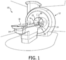
- Fig. 1 shows a partial schematic view of an embodiment of a magnetic resonance imaging system 10 in accordance with the invention.
- the magnetic resonance imaging system 10 is configured for acquiring magnetic resonance images of at least a portion of a subject of interest and comprises a scanner unit 12.
- the scanner unit 12 includes a superconducting main magnet with a magnet bore 16 arranged along a center axis 18.
- the main magnet is configured for generating a static, homogeneous magnetic field B 0 in the magnet bore 16, in which an examination space 20 is provided for positioning at least the portion of the subject of interest within during acquiring the magnetic resonance images.
- the examination space 20 is of cylindrical shape.
- An axis of symmetry of the examination space 20 coincides with the center axis 18.
- a protective bore cover 22 is arranged within the magnet bore 16.
- the magnetic resonance imaging system 10 further includes a magnetic gradient coil system configured for generating gradient magnetic fields superimposed to the static magnetic field B 0 , a radio frequency transmitter antenna configured for applying a radio frequency excitation field B 1 to nuclei of or within the portion of the subject of interest for magnetic resonance excitation, a radiofrequency receiver antenna configured for receiving magnetic resonance signals from the nuclei of or within the portion of the subject of interest that have been excited by applying the radio frequency excitation field B 1 , a patient table 14 for supporting the subject of interest and for positioning the subject of interest within the examination space, and a control unit configured for controlling functions of the magnetic resonance imaging system 10 and including a signal processing unit. All these components are well known in the field of magnetic resonance imaging and will therefore neither be discussed in more detail nor shown in the figures herein.
- the scanner unit 12 further includes a convex-shaped front cover 24 having an opening about the center axis 18 provided for the subject of interest to enter the examination space 20 for positioning the portion of the subject of interest to be imaged within the examination space 20.
- a convex-shaped front cover 24 having an opening about the center axis 18 provided for the subject of interest to enter the examination space 20 for positioning the portion of the subject of interest to be imaged within the examination space 20.
- an outer surface of the front cover 24 and an outer surface of the bore cover 22 are designed to form a smooth transition.
- a bore region 26 includes the bore cover 22 and a portion of the front cover 24 following the bore cover 22 and extending to about 50% of the width of the front cover 24.
- the front cover 24 is made from a translucent plastic material. An opaque foil whose function will be described in the following is attached to the rear surface of the front cover 24.
- the embodiments are described to include a convex-shaped front cover, it is readily acknowledged by the one skilled in the art that the front cover may as well have a flat shape.
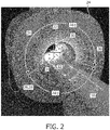
- Fig. 2 illustrates a part of the magnetic resonance imaging system 10 pursuant to Fig. 1 with a bore region lighting unit 28 in accordance with the invention.
- the bore region lighting unit 28 comprises lighting members 32, 36 and is configured for generating lighting conditions at the bore region 26 by using the lighting members 32, 36.
- the bore region lighting unit 28 includes a bore cover lighting unit 30 and a front cover lighting unit 34.
- the bore cover lighting unit 30 comprises lighting members 32 formed by optical fiber ends that emit light provided by an external light source (not shown).
- the lighting members 32 are arranged behind the translucent bore cover 22.
- the bore cover lighting unit 30 is configured, in at least one state of operation, for generating lighting conditions at the bore cover 22.
- the front cover lighting unit 34 includes lighting members 36 and is configured, in at least one state of operation, for generating lighting conditions at the front cover 24.
- the lighting members 36 are formed by a plurality of apertures in the opaque foil attached at the rear surface of the translucent front cover 24.
- the apertures are formed as circular dots of varying size and are arranged in the front cover portion of the bore region 26.
- the front cover 24 can be illuminated from behind by light sources of the front cover lighting unit 34 formed by light emitting diodes, so that the lighting members 36 of the front cover lighting unit 34 appear as circular light dots.
- the lighting members 36 of the front cover lighting unit 34 are arranged in a regular pattern at the outer surface of the front cover 24. In a cylindrical coordinate system whose z-axis is given by the center axis 18, the regular pattern of the lighting members 36 consists of two continuous angular segments ⁇ 1 , ⁇ 2 of the full circle about the center axis 18.
- the size of the circular apertures in the opaque foil is designed to increase in a direction towards the magnet bore 16, i.e. with decreasing radial distance r to the center axis 18.
- the photometric parameter given by the luminous flux of each lighting member 36 of the front cover lighting unit 34 depends on the radial distance r of the lighting member 36 to the center axis 18, namely in that it increases with decreasing radial distance r. Consequently, regions of the front cover 24 that are closer to the magnet bore 16 appear brighter than regions further away.
- a lighting condition at the bore region 26 is generated in which the bore cover 22 is uniformly illuminated by the bore cover lighting unit 30 and the front cover lighting unit 34 is activated, the subject of interest's optical perception regarding a radial dimension b of the magnet bore 16 is being influenced by generating an optical illusion and by camouflaging the magnet bore 16 with light in the way that the radial dimension b of the magnet bore 16 appears to be larger than it actually is.
- the camouflaging of the magnet bore 216 with light is carried out to the same effect in the opposite manner.
- the size of the circular apertures in the opaque foil is designed to decrease in a direction towards the magnet bore 216, i.e. with decreasing radial distance r to the center axis 218.
- the photometric parameter given by the luminous flux of each lighting member 236 of the front cover lighting unit 234 depends on the radial distance r of the lighting member 236 to the center axis 218 in that it decreases with decreasing radial distance r. Consequently, regions of the front cover 224 that are closer to the magnet bore 216 appear darker than regions further away.
- this is combined with the bore cover lighting unit 230 being turned down, so that the subject of interest's optical perception regarding the radial dimension b of the magnet bore 216 is being influenced by generating an optical illusion and by camouflaging the magnet bore 216 in the way that the radial dimension b of the magnet bore 216 appears to be larger than it actually is.
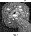
- a shape of lighting members 336 at the outer surface of the front cover 324 is designed as a radially arranged stripe.
- the lighting members 336 are formed by a plurality of apertures in an opaque foil attached to the rear surface of the translucent front cover 324.
- a stripe width of each lighting member 336 decreases with decreasing radial distance r to the center axis 318, so that regions of the front cover 324 that are closer to the magnet bore 316 appear darker than regions further away.
- the same influencing of the subject of interest's optical perception regarding a radial dimension b of the magnet bore 316 is accomplished as in the embodiment pursuant to Fig. 3 .
- each lighting member increases with decreasing radial distance to the center axis, so that regions of the front cover that are closer to the magnet bore appear brighter than regions further way, and in combination with a lighting condition at the bore region in which the bore cover is uniformly illuminated by the bore cover lighting unit, a camouflaging effect can be achieved that influences the subject of interest's optical perception with regard to the radial dimension of the magnet bore in the way that the radial dimension of the magnet bore appears to be larger than it actually is.
- a shape of lighting members 436 at the outer surface of the front cover 424 is designed as an azimuthally arranged stripe whose width is constant along an azimuthal angle.
- the lighting members 436 are formed by a plurality of apertures in an opaque foil attached to the rear surface of the translucent front cover 424.
- the stripe width of the lighting members 436 decreases with decreasing radial distance r to the center axis 418, so that regions of the front cover 424 that are closer to the magnet bore 416 appear darker than regions further away.
- the same influencing of the subject of interest's optical perception regarding a radial dimension b of the magnet bore 416 is accomplished as in the embodiments pursuant to Fig. 3 and 4 .
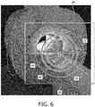
- a bore region lighting unit 228, 328, 428 pursuant to Figs. 3 , 4 and 5 can be described by introducing a virtual plane 38 ( Fig. 6 ) that is arranged perpendicularly to the center axis 18 and in front of the front cover 24, and by analyzing a brightness-related photometric parameter for locations in azimuthally arranged annular regions 40 of the virtual plane 38 and at the described generated lighting conditions.
- the illuminance I created by the generated lighting condition is averaged over the area of the annular region 40 to obtain an area-averaged illuminance Î.
- the radial width 42 of each of the annular regions 40 is selected such that at least ten dot-shaped lighting members 36 of the front cover lighting unit 34 are covered by each annular region 40.
- the area-averaged illuminance Î increases in the radial direction towards the center axis 18 for a continuous range ⁇ 1 of the azimuthal angle about the center axis 18 if the bore cover 22 is illuminated (in this embodiment: uniformly illuminated) by the bore cover lighting unit 30.
- a front cover is made from a translucent plastic material.
- the front cover lighting unit comprises light sources arranged behind the front cover as lighting members.
- the plastic material of the front cover is sufficiently opaque to scatter light emitted by the light sources such that no details of the light source are visible from the outside.
- a bore cover lighting unit comprises lighting members formed by optical fiber ends that emit light provided by an external light source. The lighting members are arranged behind a translucent bore cover and generate lighting condition of homogeneous illumination at the bore cover.
- a radial width of the azimuthally arranged annular regions was selected sufficiently small, one would find that a first derivative of an illuminance function I, taken with respect to a radial direction towards the center axis, is continuous, in the mathematical sense, in the radial interval given by the distance of the outermost lighting member of the bore region lighting unit from the center axis and a radial dimension b of the bore cover for a continuous range of an azimuth angle about the center axis.
- illuminance function I An example for such an illuminance function I is given in Fig. 7 , showing that shadows or any dark/light contrast zones are avoided in the bore region.
- a maximum of the illuminance function I is located at a radial coordinate r arranged outside the magnet bore, which makes the generated optical illusion in connection with the radial dimension b of the magnet bore very convincing to the subject of interest and effectively influences the subject of interest's optical perception regarding the radial dimension b of the magnet bore.
- the bore region lighting unit is configured, in at least one state of operation, to dynamically switch selected lighting members of the front cover lighting unit between an illuminated on-state and extinguished of-state of the lighting member.
- the dynamically switching comprises initiating the change of a color of the selected lighting members of the front cover lighting unit. In this way, the optical perception of the subject of interest regarding the radial dimension of the magnet bore is influenced by detracting the subject of interest's attention towards the dynamically switched lighting members and the color-changing lighting members, respectively.
Landscapes
- Physics & Mathematics (AREA)
- Engineering & Computer Science (AREA)
- Condensed Matter Physics & Semiconductors (AREA)
- General Physics & Mathematics (AREA)
- General Engineering & Computer Science (AREA)
- Health & Medical Sciences (AREA)
- Biomedical Technology (AREA)
- Signal Processing (AREA)
- High Energy & Nuclear Physics (AREA)
- Magnetic Resonance Imaging Apparatus (AREA)
Applications Claiming Priority (3)
| Application Number | Priority Date | Filing Date | Title |
|---|---|---|---|
| CN2014080829 | 2014-06-26 | ||
| EP14181175 | 2014-08-15 | ||
| PCT/EP2015/063621 WO2015197451A1 (en) | 2014-06-26 | 2015-06-17 | Bore region lighting unit for magnetic resonance scanner |
Publications (2)
| Publication Number | Publication Date |
|---|---|
| EP3161501A1 EP3161501A1 (en) | 2017-05-03 |
| EP3161501B1 true EP3161501B1 (en) | 2021-08-11 |
Family
ID=53396513
Family Applications (1)
| Application Number | Title | Priority Date | Filing Date |
|---|---|---|---|
| EP15728900.0A Active EP3161501B1 (en) | 2014-06-26 | 2015-06-17 | Bore region lighting unit for magnetic resonance scanner |
Country Status (5)
| Country | Link |
|---|---|
| US (1) | US10261142B2 (enExample) |
| EP (1) | EP3161501B1 (enExample) |
| JP (1) | JP6588478B2 (enExample) |
| CN (1) | CN106461744B (enExample) |
| WO (1) | WO2015197451A1 (enExample) |
Families Citing this family (5)
| Publication number | Priority date | Publication date | Assignee | Title |
|---|---|---|---|---|
| USD818126S1 (en) * | 2016-11-23 | 2018-05-15 | General Electric Company | Magnetic resonance imaging device |
| USD878596S1 (en) * | 2017-10-31 | 2020-03-17 | Koninklijke Philips N.V. | Front of an MR scanner |
| USD868971S1 (en) * | 2017-10-31 | 2019-12-03 | Koninklijke Phillips N.V. | Front of an MR scanner |
| USD868261S1 (en) * | 2017-10-31 | 2019-11-26 | Koninklijke Philips N.V. | Front of an MR scanner |
| USD996618S1 (en) * | 2022-02-15 | 2023-08-22 | Siemens Healthcare Gmbh | Medical imaging device |
Family Cites Families (14)
| Publication number | Priority date | Publication date | Assignee | Title |
|---|---|---|---|---|
| US4613926A (en) | 1984-10-31 | 1986-09-23 | General Electric Company | Fiber optic illuminating assembly |
| JPH05146423A (ja) * | 1991-11-29 | 1993-06-15 | Shimadzu Corp | Mri装置 |
| JP3192453B2 (ja) * | 1991-12-12 | 2001-07-30 | 株式会社日立メディコ | 磁気共鳴検査装置 |
| DE10158313A1 (de) * | 2001-11-28 | 2003-06-26 | Siemens Ag | Medizinisches Untersuchungsgerät mit optisch vergrößertem Innenraum |
| DE10322140B4 (de) | 2003-05-16 | 2008-07-10 | Siemens Ag | Bildgebendes medizinisches Untersuchungsgerät |
| DE102004024095A1 (de) * | 2004-05-14 | 2005-12-15 | Siemens Ag | Beleuchtungsvorrichtung und bildgebendes medizinisches Untersuchungsgerät mit einer derartigen Beleuchtungsvorrichtung |
| GB0615600D0 (en) * | 2006-08-07 | 2006-09-13 | Siemens Magnet Technology Ltd | Imaging magnet with illuminated bore |
| JP5348870B2 (ja) * | 2006-11-24 | 2013-11-20 | 株式会社東芝 | Mri装置 |
| DE102007045325B4 (de) | 2007-09-21 | 2014-11-20 | Siemens Aktiengesellschaft | Medizinische Untersuchungsvorrichtung |
| US8691172B2 (en) * | 2008-02-25 | 2014-04-08 | Kbi Enterprises, Llc | Forsterite and method for making |
| US9532727B2 (en) * | 2008-06-06 | 2017-01-03 | Koninklijke Philips N.V. | Method and apparatus for illuminating the interior of a medical imaging device |
| WO2013046906A1 (ja) * | 2011-09-30 | 2013-04-04 | 株式会社日立メディコ | 検査装置 |
| WO2013105668A1 (ja) * | 2012-01-13 | 2013-07-18 | 株式会社東芝 | 磁気共鳴イメージング装置及び医用画像診断装置 |
| DE102012215130B4 (de) | 2012-08-24 | 2024-11-14 | Siemens Healthineers Ag | Medizinisches Gerät mit mindestens einem Beleuchtungsmittel |
-
2015
- 2015-06-17 JP JP2016575147A patent/JP6588478B2/ja not_active Expired - Fee Related
- 2015-06-17 US US15/319,083 patent/US10261142B2/en active Active
- 2015-06-17 CN CN201580034487.8A patent/CN106461744B/zh not_active Expired - Fee Related
- 2015-06-17 WO PCT/EP2015/063621 patent/WO2015197451A1/en not_active Ceased
- 2015-06-17 EP EP15728900.0A patent/EP3161501B1/en active Active
Non-Patent Citations (1)
| Title |
|---|
| None * |
Also Published As
| Publication number | Publication date |
|---|---|
| CN106461744B (zh) | 2020-02-07 |
| WO2015197451A1 (en) | 2015-12-30 |
| EP3161501A1 (en) | 2017-05-03 |
| US20170131370A1 (en) | 2017-05-11 |
| US10261142B2 (en) | 2019-04-16 |
| JP2017518839A (ja) | 2017-07-13 |
| CN106461744A (zh) | 2017-02-22 |
| JP6588478B2 (ja) | 2019-10-09 |
Similar Documents
| Publication | Publication Date | Title |
|---|---|---|
| EP3161501B1 (en) | Bore region lighting unit for magnetic resonance scanner | |
| EP2288288B1 (en) | Method and apparatus for illuminating the interior of a medical imaging device | |
| US9335165B2 (en) | Sighting device | |
| US7702375B2 (en) | Medical imaging apparatus illuminated to reduce patient anxiety | |
| US8579450B2 (en) | Sighting device containing an elongated body made from light conducting or light collecting material and coaxially disposed with a light source | |
| US7852080B2 (en) | MRI apparatus including a lighting unit | |
| US20170156578A1 (en) | Medical instrument having led illumination system | |
| JP2017512983A (ja) | 発光インジケータ付きセンサ | |
| WO2016005339A1 (en) | Lighting device and method for masking an edge transition | |
| EP2781827A2 (en) | Vehicle lamp | |
| CN110809528B (zh) | 车辆用显示装置、拍摄系统以及照明装置 | |
| CN103982860B (zh) | 在光学系统中当作光散射的元件的结构织物和效果织物 | |
| JP2017518839A5 (enExample) | ||
| JP3714640B2 (ja) | 計器装置 | |
| CA2692088A1 (en) | Nvg compatible illumination device based on light-emitting diodes | |
| JP2016184532A (ja) | 表示灯 | |
| JP2007121177A (ja) | 指示計器 | |
| CN109008947A (zh) | 一种高精准检测率的吸毒人员瞳孔检测仪 | |
| JP6152732B2 (ja) | 照明方法及び照明システム | |
| JP2013213775A (ja) | 指針表示装置 | |
| US20120085935A1 (en) | Apparatus for Seeing Fluorescent Indicia in Dark Conditions | |
| CN121152941A (zh) | 控制台光导装置 | |
| US20170010136A1 (en) | Light conductor device for indicating light pointer and meter device including the same | |
| CZ2012372A3 (cs) | Ozarovací zarízení pro CCTV kamery | |
| WO2016121712A1 (ja) | Led信号灯 |
Legal Events
| Date | Code | Title | Description |
|---|---|---|---|
| STAA | Information on the status of an ep patent application or granted ep patent |
Free format text: STATUS: THE INTERNATIONAL PUBLICATION HAS BEEN MADE |
|
| PUAI | Public reference made under article 153(3) epc to a published international application that has entered the european phase |
Free format text: ORIGINAL CODE: 0009012 |
|
| STAA | Information on the status of an ep patent application or granted ep patent |
Free format text: STATUS: REQUEST FOR EXAMINATION WAS MADE |
|
| 17P | Request for examination filed |
Effective date: 20170126 |
|
| AK | Designated contracting states |
Kind code of ref document: A1 Designated state(s): AL AT BE BG CH CY CZ DE DK EE ES FI FR GB GR HR HU IE IS IT LI LT LU LV MC MK MT NL NO PL PT RO RS SE SI SK SM TR |
|
| AX | Request for extension of the european patent |
Extension state: BA ME |
|
| DAV | Request for validation of the european patent (deleted) | ||
| DAX | Request for extension of the european patent (deleted) | ||
| STAA | Information on the status of an ep patent application or granted ep patent |
Free format text: STATUS: EXAMINATION IS IN PROGRESS |
|
| RAP1 | Party data changed (applicant data changed or rights of an application transferred) |
Owner name: KONINKLIJKE PHILIPS N.V. |
|
| 17Q | First examination report despatched |
Effective date: 20200305 |
|
| GRAP | Despatch of communication of intention to grant a patent |
Free format text: ORIGINAL CODE: EPIDOSNIGR1 |
|
| STAA | Information on the status of an ep patent application or granted ep patent |
Free format text: STATUS: GRANT OF PATENT IS INTENDED |
|
| INTG | Intention to grant announced |
Effective date: 20210128 |
|
| GRAS | Grant fee paid |
Free format text: ORIGINAL CODE: EPIDOSNIGR3 |
|
| GRAA | (expected) grant |
Free format text: ORIGINAL CODE: 0009210 |
|
| STAA | Information on the status of an ep patent application or granted ep patent |
Free format text: STATUS: THE PATENT HAS BEEN GRANTED |
|
| AK | Designated contracting states |
Kind code of ref document: B1 Designated state(s): AL AT BE BG CH CY CZ DE DK EE ES FI FR GB GR HR HU IE IS IT LI LT LU LV MC MK MT NL NO PL PT RO RS SE SI SK SM TR |
|
| REG | Reference to a national code |
Ref country code: CH Ref legal event code: EP |
|
| REG | Reference to a national code |
Ref country code: DE Ref legal event code: R096 Ref document number: 602015072168 Country of ref document: DE |
|
| REG | Reference to a national code |
Ref country code: IE Ref legal event code: FG4D Ref country code: AT Ref legal event code: REF Ref document number: 1419923 Country of ref document: AT Kind code of ref document: T Effective date: 20210915 |
|
| REG | Reference to a national code |
Ref country code: DE Ref legal event code: R084 Ref document number: 602015072168 Country of ref document: DE |
|
| REG | Reference to a national code |
Ref country code: LT Ref legal event code: MG9D |
|
| REG | Reference to a national code |
Ref country code: NL Ref legal event code: MP Effective date: 20210811 |
|
| REG | Reference to a national code |
Ref country code: AT Ref legal event code: MK05 Ref document number: 1419923 Country of ref document: AT Kind code of ref document: T Effective date: 20210811 |
|
| PG25 | Lapsed in a contracting state [announced via postgrant information from national office to epo] |
Ref country code: HR Free format text: LAPSE BECAUSE OF FAILURE TO SUBMIT A TRANSLATION OF THE DESCRIPTION OR TO PAY THE FEE WITHIN THE PRESCRIBED TIME-LIMIT Effective date: 20210811 Ref country code: SE Free format text: LAPSE BECAUSE OF FAILURE TO SUBMIT A TRANSLATION OF THE DESCRIPTION OR TO PAY THE FEE WITHIN THE PRESCRIBED TIME-LIMIT Effective date: 20210811 Ref country code: RS Free format text: LAPSE BECAUSE OF FAILURE TO SUBMIT A TRANSLATION OF THE DESCRIPTION OR TO PAY THE FEE WITHIN THE PRESCRIBED TIME-LIMIT Effective date: 20210811 Ref country code: ES Free format text: LAPSE BECAUSE OF FAILURE TO SUBMIT A TRANSLATION OF THE DESCRIPTION OR TO PAY THE FEE WITHIN THE PRESCRIBED TIME-LIMIT Effective date: 20210811 Ref country code: FI Free format text: LAPSE BECAUSE OF FAILURE TO SUBMIT A TRANSLATION OF THE DESCRIPTION OR TO PAY THE FEE WITHIN THE PRESCRIBED TIME-LIMIT Effective date: 20210811 Ref country code: PT Free format text: LAPSE BECAUSE OF FAILURE TO SUBMIT A TRANSLATION OF THE DESCRIPTION OR TO PAY THE FEE WITHIN THE PRESCRIBED TIME-LIMIT Effective date: 20211213 Ref country code: NO Free format text: LAPSE BECAUSE OF FAILURE TO SUBMIT A TRANSLATION OF THE DESCRIPTION OR TO PAY THE FEE WITHIN THE PRESCRIBED TIME-LIMIT Effective date: 20211111 Ref country code: AT Free format text: LAPSE BECAUSE OF FAILURE TO SUBMIT A TRANSLATION OF THE DESCRIPTION OR TO PAY THE FEE WITHIN THE PRESCRIBED TIME-LIMIT Effective date: 20210811 Ref country code: BG Free format text: LAPSE BECAUSE OF FAILURE TO SUBMIT A TRANSLATION OF THE DESCRIPTION OR TO PAY THE FEE WITHIN THE PRESCRIBED TIME-LIMIT Effective date: 20211111 Ref country code: LT Free format text: LAPSE BECAUSE OF FAILURE TO SUBMIT A TRANSLATION OF THE DESCRIPTION OR TO PAY THE FEE WITHIN THE PRESCRIBED TIME-LIMIT Effective date: 20210811 |
|
| PG25 | Lapsed in a contracting state [announced via postgrant information from national office to epo] |
Ref country code: PL Free format text: LAPSE BECAUSE OF FAILURE TO SUBMIT A TRANSLATION OF THE DESCRIPTION OR TO PAY THE FEE WITHIN THE PRESCRIBED TIME-LIMIT Effective date: 20210811 Ref country code: LV Free format text: LAPSE BECAUSE OF FAILURE TO SUBMIT A TRANSLATION OF THE DESCRIPTION OR TO PAY THE FEE WITHIN THE PRESCRIBED TIME-LIMIT Effective date: 20210811 Ref country code: GR Free format text: LAPSE BECAUSE OF FAILURE TO SUBMIT A TRANSLATION OF THE DESCRIPTION OR TO PAY THE FEE WITHIN THE PRESCRIBED TIME-LIMIT Effective date: 20211112 |
|
| PG25 | Lapsed in a contracting state [announced via postgrant information from national office to epo] |
Ref country code: NL Free format text: LAPSE BECAUSE OF FAILURE TO SUBMIT A TRANSLATION OF THE DESCRIPTION OR TO PAY THE FEE WITHIN THE PRESCRIBED TIME-LIMIT Effective date: 20210811 |
|
| PG25 | Lapsed in a contracting state [announced via postgrant information from national office to epo] |
Ref country code: DK Free format text: LAPSE BECAUSE OF FAILURE TO SUBMIT A TRANSLATION OF THE DESCRIPTION OR TO PAY THE FEE WITHIN THE PRESCRIBED TIME-LIMIT Effective date: 20210811 |
|
| REG | Reference to a national code |
Ref country code: DE Ref legal event code: R097 Ref document number: 602015072168 Country of ref document: DE |
|
| PG25 | Lapsed in a contracting state [announced via postgrant information from national office to epo] |
Ref country code: SM Free format text: LAPSE BECAUSE OF FAILURE TO SUBMIT A TRANSLATION OF THE DESCRIPTION OR TO PAY THE FEE WITHIN THE PRESCRIBED TIME-LIMIT Effective date: 20210811 Ref country code: SK Free format text: LAPSE BECAUSE OF FAILURE TO SUBMIT A TRANSLATION OF THE DESCRIPTION OR TO PAY THE FEE WITHIN THE PRESCRIBED TIME-LIMIT Effective date: 20210811 Ref country code: RO Free format text: LAPSE BECAUSE OF FAILURE TO SUBMIT A TRANSLATION OF THE DESCRIPTION OR TO PAY THE FEE WITHIN THE PRESCRIBED TIME-LIMIT Effective date: 20210811 Ref country code: EE Free format text: LAPSE BECAUSE OF FAILURE TO SUBMIT A TRANSLATION OF THE DESCRIPTION OR TO PAY THE FEE WITHIN THE PRESCRIBED TIME-LIMIT Effective date: 20210811 Ref country code: CZ Free format text: LAPSE BECAUSE OF FAILURE TO SUBMIT A TRANSLATION OF THE DESCRIPTION OR TO PAY THE FEE WITHIN THE PRESCRIBED TIME-LIMIT Effective date: 20210811 Ref country code: AL Free format text: LAPSE BECAUSE OF FAILURE TO SUBMIT A TRANSLATION OF THE DESCRIPTION OR TO PAY THE FEE WITHIN THE PRESCRIBED TIME-LIMIT Effective date: 20210811 |
|
| PLBE | No opposition filed within time limit |
Free format text: ORIGINAL CODE: 0009261 |
|
| STAA | Information on the status of an ep patent application or granted ep patent |
Free format text: STATUS: NO OPPOSITION FILED WITHIN TIME LIMIT |
|
| 26N | No opposition filed |
Effective date: 20220512 |
|
| PG25 | Lapsed in a contracting state [announced via postgrant information from national office to epo] |
Ref country code: IT Free format text: LAPSE BECAUSE OF FAILURE TO SUBMIT A TRANSLATION OF THE DESCRIPTION OR TO PAY THE FEE WITHIN THE PRESCRIBED TIME-LIMIT Effective date: 20210811 |
|
| PG25 | Lapsed in a contracting state [announced via postgrant information from national office to epo] |
Ref country code: SI Free format text: LAPSE BECAUSE OF FAILURE TO SUBMIT A TRANSLATION OF THE DESCRIPTION OR TO PAY THE FEE WITHIN THE PRESCRIBED TIME-LIMIT Effective date: 20210811 |
|
| PGFP | Annual fee paid to national office [announced via postgrant information from national office to epo] |
Ref country code: DE Payment date: 20220628 Year of fee payment: 8 |
|
| PG25 | Lapsed in a contracting state [announced via postgrant information from national office to epo] |
Ref country code: MC Free format text: LAPSE BECAUSE OF FAILURE TO SUBMIT A TRANSLATION OF THE DESCRIPTION OR TO PAY THE FEE WITHIN THE PRESCRIBED TIME-LIMIT Effective date: 20210811 |
|
| REG | Reference to a national code |
Ref country code: CH Ref legal event code: PL |
|
| REG | Reference to a national code |
Ref country code: BE Ref legal event code: MM Effective date: 20220630 |
|
| GBPC | Gb: european patent ceased through non-payment of renewal fee |
Effective date: 20220617 |
|
| PG25 | Lapsed in a contracting state [announced via postgrant information from national office to epo] |
Ref country code: LU Free format text: LAPSE BECAUSE OF NON-PAYMENT OF DUE FEES Effective date: 20220617 Ref country code: LI Free format text: LAPSE BECAUSE OF NON-PAYMENT OF DUE FEES Effective date: 20220630 Ref country code: IE Free format text: LAPSE BECAUSE OF NON-PAYMENT OF DUE FEES Effective date: 20220617 Ref country code: FR Free format text: LAPSE BECAUSE OF NON-PAYMENT OF DUE FEES Effective date: 20220630 Ref country code: CH Free format text: LAPSE BECAUSE OF NON-PAYMENT OF DUE FEES Effective date: 20220630 |
|
| PG25 | Lapsed in a contracting state [announced via postgrant information from national office to epo] |
Ref country code: GB Free format text: LAPSE BECAUSE OF NON-PAYMENT OF DUE FEES Effective date: 20220617 Ref country code: BE Free format text: LAPSE BECAUSE OF NON-PAYMENT OF DUE FEES Effective date: 20220630 |
|
| REG | Reference to a national code |
Ref country code: DE Ref legal event code: R119 Ref document number: 602015072168 Country of ref document: DE |
|
| PG25 | Lapsed in a contracting state [announced via postgrant information from national office to epo] |
Ref country code: HU Free format text: LAPSE BECAUSE OF FAILURE TO SUBMIT A TRANSLATION OF THE DESCRIPTION OR TO PAY THE FEE WITHIN THE PRESCRIBED TIME-LIMIT; INVALID AB INITIO Effective date: 20150617 |
|
| PG25 | Lapsed in a contracting state [announced via postgrant information from national office to epo] |
Ref country code: MK Free format text: LAPSE BECAUSE OF FAILURE TO SUBMIT A TRANSLATION OF THE DESCRIPTION OR TO PAY THE FEE WITHIN THE PRESCRIBED TIME-LIMIT Effective date: 20210811 Ref country code: DE Free format text: LAPSE BECAUSE OF NON-PAYMENT OF DUE FEES Effective date: 20240103 Ref country code: CY Free format text: LAPSE BECAUSE OF FAILURE TO SUBMIT A TRANSLATION OF THE DESCRIPTION OR TO PAY THE FEE WITHIN THE PRESCRIBED TIME-LIMIT Effective date: 20210811 |
|
| PG25 | Lapsed in a contracting state [announced via postgrant information from national office to epo] |
Ref country code: MT Free format text: LAPSE BECAUSE OF FAILURE TO SUBMIT A TRANSLATION OF THE DESCRIPTION OR TO PAY THE FEE WITHIN THE PRESCRIBED TIME-LIMIT Effective date: 20210811 |
|
| PG25 | Lapsed in a contracting state [announced via postgrant information from national office to epo] |
Ref country code: TR Free format text: LAPSE BECAUSE OF FAILURE TO SUBMIT A TRANSLATION OF THE DESCRIPTION OR TO PAY THE FEE WITHIN THE PRESCRIBED TIME-LIMIT Effective date: 20210811 |