EP2781827A2 - Vehicle lamp - Google Patents
Vehicle lamp Download PDFInfo
- Publication number
- EP2781827A2 EP2781827A2 EP20140160942 EP14160942A EP2781827A2 EP 2781827 A2 EP2781827 A2 EP 2781827A2 EP 20140160942 EP20140160942 EP 20140160942 EP 14160942 A EP14160942 A EP 14160942A EP 2781827 A2 EP2781827 A2 EP 2781827A2
- Authority
- EP
- European Patent Office
- Prior art keywords
- light
- emitting device
- emitting
- vehicle lamp
- surface light
- Prior art date
- Legal status (The legal status is an assumption and is not a legal conclusion. Google has not performed a legal analysis and makes no representation as to the accuracy of the status listed.)
- Granted
Links
Images


Classifications
-
- F—MECHANICAL ENGINEERING; LIGHTING; HEATING; WEAPONS; BLASTING
- F21—LIGHTING
- F21S—NON-PORTABLE LIGHTING DEVICES; SYSTEMS THEREOF; VEHICLE LIGHTING DEVICES SPECIALLY ADAPTED FOR VEHICLE EXTERIORS
- F21S43/00—Signalling devices specially adapted for vehicle exteriors, e.g. brake lamps, direction indicator lights or reversing lights
- F21S43/30—Signalling devices specially adapted for vehicle exteriors, e.g. brake lamps, direction indicator lights or reversing lights characterised by reflectors
-
- B—PERFORMING OPERATIONS; TRANSPORTING
- B60—VEHICLES IN GENERAL
- B60Q—ARRANGEMENT OF SIGNALLING OR LIGHTING DEVICES, THE MOUNTING OR SUPPORTING THEREOF OR CIRCUITS THEREFOR, FOR VEHICLES IN GENERAL
- B60Q1/00—Arrangement of optical signalling or lighting devices, the mounting or supporting thereof or circuits therefor
- B60Q1/0029—Spatial arrangement
- B60Q1/0041—Spatial arrangement of several lamps in relation to each other
-
- B—PERFORMING OPERATIONS; TRANSPORTING
- B60—VEHICLES IN GENERAL
- B60Q—ARRANGEMENT OF SIGNALLING OR LIGHTING DEVICES, THE MOUNTING OR SUPPORTING THEREOF OR CIRCUITS THEREFOR, FOR VEHICLES IN GENERAL
- B60Q1/00—Arrangement of optical signalling or lighting devices, the mounting or supporting thereof or circuits therefor
- B60Q1/26—Arrangement of optical signalling or lighting devices, the mounting or supporting thereof or circuits therefor the devices being primarily intended to indicate the vehicle, or parts thereof, or to give signals, to other traffic
- B60Q1/2607—Arrangement of optical signalling or lighting devices, the mounting or supporting thereof or circuits therefor the devices being primarily intended to indicate the vehicle, or parts thereof, or to give signals, to other traffic comprising at least two indicating lamps
-
- F—MECHANICAL ENGINEERING; LIGHTING; HEATING; WEAPONS; BLASTING
- F21—LIGHTING
- F21S—NON-PORTABLE LIGHTING DEVICES; SYSTEMS THEREOF; VEHICLE LIGHTING DEVICES SPECIALLY ADAPTED FOR VEHICLE EXTERIORS
- F21S43/00—Signalling devices specially adapted for vehicle exteriors, e.g. brake lamps, direction indicator lights or reversing lights
- F21S43/10—Signalling devices specially adapted for vehicle exteriors, e.g. brake lamps, direction indicator lights or reversing lights characterised by the light source
- F21S43/13—Signalling devices specially adapted for vehicle exteriors, e.g. brake lamps, direction indicator lights or reversing lights characterised by the light source characterised by the type of light source
- F21S43/14—Light emitting diodes [LED]
- F21S43/145—Surface emitters, e.g. organic light emitting diodes [OLED]
-
- F—MECHANICAL ENGINEERING; LIGHTING; HEATING; WEAPONS; BLASTING
- F21—LIGHTING
- F21S—NON-PORTABLE LIGHTING DEVICES; SYSTEMS THEREOF; VEHICLE LIGHTING DEVICES SPECIALLY ADAPTED FOR VEHICLE EXTERIORS
- F21S43/00—Signalling devices specially adapted for vehicle exteriors, e.g. brake lamps, direction indicator lights or reversing lights
- F21S43/10—Signalling devices specially adapted for vehicle exteriors, e.g. brake lamps, direction indicator lights or reversing lights characterised by the light source
- F21S43/13—Signalling devices specially adapted for vehicle exteriors, e.g. brake lamps, direction indicator lights or reversing lights characterised by the light source characterised by the type of light source
- F21S43/15—Strips of light sources
-
- F—MECHANICAL ENGINEERING; LIGHTING; HEATING; WEAPONS; BLASTING
- F21—LIGHTING
- F21S—NON-PORTABLE LIGHTING DEVICES; SYSTEMS THEREOF; VEHICLE LIGHTING DEVICES SPECIALLY ADAPTED FOR VEHICLE EXTERIORS
- F21S43/00—Signalling devices specially adapted for vehicle exteriors, e.g. brake lamps, direction indicator lights or reversing lights
- F21S43/10—Signalling devices specially adapted for vehicle exteriors, e.g. brake lamps, direction indicator lights or reversing lights characterised by the light source
- F21S43/19—Attachment of light sources or lamp holders
-
- F—MECHANICAL ENGINEERING; LIGHTING; HEATING; WEAPONS; BLASTING
- F21—LIGHTING
- F21S—NON-PORTABLE LIGHTING DEVICES; SYSTEMS THEREOF; VEHICLE LIGHTING DEVICES SPECIALLY ADAPTED FOR VEHICLE EXTERIORS
- F21S43/00—Signalling devices specially adapted for vehicle exteriors, e.g. brake lamps, direction indicator lights or reversing lights
- F21S43/30—Signalling devices specially adapted for vehicle exteriors, e.g. brake lamps, direction indicator lights or reversing lights characterised by reflectors
- F21S43/33—Signalling devices specially adapted for vehicle exteriors, e.g. brake lamps, direction indicator lights or reversing lights characterised by reflectors characterised by their material, surface treatment or coatings
-
- B—PERFORMING OPERATIONS; TRANSPORTING
- B60—VEHICLES IN GENERAL
- B60Q—ARRANGEMENT OF SIGNALLING OR LIGHTING DEVICES, THE MOUNTING OR SUPPORTING THEREOF OR CIRCUITS THEREFOR, FOR VEHICLES IN GENERAL
- B60Q2400/00—Special features or arrangements of exterior signal lamps for vehicles
- B60Q2400/10—Electro- or photo- luminescent surfaces, e.g. signalling by way of electroluminescent strips or panels
Definitions
- the present invention relates to a vehicle lamp and, more particularly, to a vehicle lamp having a light source with a surface light-emitting device.
- a related art vehicle lamp is configured such that an optical member reflecting light from a light source gives a radially light-emitting appearance (see, e.g., JP 2008-059901A ).
- this vehicle lamp has a relatively complex configuration. For example, some portions of the reflector are configured to totally reflect the light from the light source and other portions of the reflector are configured to transmit the light from the light source. Further, the lamp requires a number of components, including multiple reflectors and sometimes multiple light sources, resulting in an increase in manufacturing cost.
- One or more embodiments of the present invention provides a vehicle lamp having a desired light-emitting appearance at low cost.
- a vehicle lamp includes a light source and an optical member configured to reflect light from the light source.
- the light source includes a base extending in a front-rear direction of the vehicle lamp and a surface light-emitting device provided on the base.
- the surface light-emitting device is configured and arranged to project a pattern on the optical member.
- the light emitted by the surface light-emitting device and reflected by the optical member gives a patterned appearance.
- Fig. 1 is a front view showing a vehicle lamp 100 according to one ore more embodiments of the present invention.
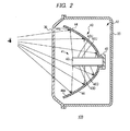
- Fig. 2 is a sectional view of the vehicle lamp 100, taken along the line II-II of Fig. 1 .
- Fig. 3 is a perspective view illustrating a light source 41.
- the vehicle lamp 100 includes a lamp body 20, a transparent cover 30 and a lamp unit 40. In Fig. 1 , the transparent cover 30 is removed to better illustrate an internal configuration of the vehicle lamp 100.
- a side on which the transparent cover 30 is arranged is defined as a front side and a side on which the lamp body 20 is defined as a rear side. Further, a right side and a left side are defined with a view in a direction toward the front of the lamp.
- the lamp body 20 is formed in a shape like a box having an opening.
- the transparent cover 30 is has a shape like a bowl and is made of transparent resin or glass.
- the transparent cover 30 is attached to the opening portion of the lamp body 20.
- a lamp chamber 12 is formed by the lamp body 20 and the transparent cover 30.
- the lamp unit 40 is accommodated inside the lamp chamber 12.
- the lamp unit 40 includes the light source 41, a reflector 44 and a support member 45 supporting the light source 41 and the reflector 44.
- the light source 41 includes a base 42 and surface light-emitting devices 43U, 43D, 43L, 43R (hereinafter, "surface light-emitting device 43" when these light-emitting elements are collectively referred or are not particularly distinguished).
- the base 42 has a substantially rectangular column shape and is arranged to extend substantially in alignment with the front-rear direction of the lamp.
- the base 42 is made of, for example, glass or resin such as acrylic or polycarbonate.
- the surface light-emitting device 43U is firmly attached to an upper side surface 42U of the base 42
- the surface light-emitting device 43D is firmly attached to a lower side surface 42D of the base 42
- the surface light-emitting device 43L is firmly attached to a left side surface 42L of the base 42
- the surface light-emitting device 43R is firmly attached to a right side surface 42R of the base 42.
- Each surface light-emitting device 43 is an organic electro-luminescence (EL) device, and is configured in a form of a sheet having a substantially rectangular surface. More specifically, the surface light-emitting device 43 is formed to have a size and shape that covers a side surface of the base 42 excluding an edge portion of the base 42. Because the organic EL device can be easily processed to have an optional shape, the surface light-emitting device 43 can be formed to have a desired shape.
- EL organic electro-luminescence
- Each surface light-emitting device 43 includes a first substrate 51, a transparent electrode 52, an organic light-emitting layer 53, a back electrode 54, and a second substrate 55. While a configuration of only the surface light-emitting device 43U is shown in Fig. 3 , other surface light-emitting devices 43D, 43L, 43R may have the same configuration as the surface light-emitting device 43U.
- the first substrate 51 is a transparent member made of, for example, glass or the like.
- the transparent electrode 52 is made of, for example, transparent electrically-conductive material such as indium tin oxide (ITO).
- the organic light-emitting layer 53 is configured to emit light, in this embodiment, red light. That is, in this embodiment, four surface light-emitting devices 43 are configured to emit red light.
- the back electrode 54 is made of metallic material such as aluminum or magnesium.
- the second substrate 55 is made of, for example, glass, metal plate or the like.
- the organic light-emitting layer 53 emits the light toward the outside of the surface light-emitting device 43 through the transparent electrode 52 and the first substrate 51. In this way, the surface light-emitting device 43 is configured provide surface light-emission from the surface 51a of the first substrate 51.
- the reflector 44 has a curved reflecting surface 44a, and is arranged such that the center axis of the reflecting surface 44a passes through the light source 41. According to one or more embodiments of the present invention, the reflector 44 is arranged such that the center axis of the reflecting surface 44a is substantially aligned with the center axis of the base 42. With this reflecting surface 44a, the light from the four surface light-emitting devices 43 is reflected toward the front of the lamp.
- Fig. 4 illustrates a pattern projected on the reflector 44 when the light source 41 is turned on. More specifically, Fig. 4 illustrates a pattern that is observed through the transparent cover 30 from a position in front of the lamp, for example, from a position 1m in front of the lamp.
- hatched regions indicate regions that provide a red light emitting appearance. That is, the hatched regions are the regions where the light from the light source 41 reaches the reflector 44 and is reflected by the reflector 44 to give a red light emitting appearance.
- Non-hatched regions indicate regions on which the light is not projected and provide a dark appearance. As shown in Fig.
- a region 60 corresponding to an end surface of the light source 41 and regions 61, 62, 63 64 corresponding to portions of the side surfaces of the light source 41 that are not covered by the surface light-emitting devices 43 are the regions on which the light is not projected and give a dark appearance.
- a region 65 gives a red light-emitting appearance by the reflection of the light from the surface light-emitting device 43U.
- a region 66 gives a red light-emitting appearance by the reflection of the light from the surface light-emitting device 43L
- a region 67 gives a red light-emitting appearance by the reflection of the light from the surface light-emitting device 43D
- a region 68 gives a red light-emitting appearance by the reflection of the light from the surface light-emitting device 43R.
- the resulting pattern includes four sector shaped regions 65, 66, 67, 68 arranged in a circumferential direction, each giving a red light-emitting appearance. That is, a patterned light-emitting appearance is achieved by a contrast of the light.
- This type of lamp having a red light-emitting appearance may be used as, for example, a tail lamp.
- the vehicle lamp 100 described above it is possible to present a desired pattern in accordance with the contrast of light by using surface light-emitting devices 43 that can be easily processed to have an optional shape.
- the reflector 44 is described as an optical member having a function of only reflecting light from the light source 41.
- the reflector may be configured to have, in addition to the light reflecting function, a function as a light source.
- Fig. 5 is a sectional view of a vehicle lamp 200 according to one or more embodiments of the present invention.
- Fig. 5 corresponds to Fig. 2 .
- the vehicle lamp 200 includes the lamp body 20, the transparent cover 30 and a lamp unit 240.
- the lamp unit 240 includes the light source 41, a reflector 244, and the support member 45.
- the reflector 244 includes a first substrate 251, a transparent electrode 252, an organic light-emitting layer 253, a back electrode 254 and, a second substrate 255. They are similar to the first substrate 51, the transparent electrode 52, the organic light-emitting layer 53, the back electrode 54, and the second substrate 55 of the surface light-emitting device 43 of the light source 41, respectively.
- the reflector 244 reflects the light from the light source 41 toward the front of the lamp. Specifically, the light from the light source 41 enters the reflector 244 from a surface 251a of the first substrate 251 on a side facing the light source 41. The entered light is transmitted through the first substrate 251, the transparent electrode 252 and the organic light-emitting layer 253 and is reflected toward the front of the lamp at a surface 254a of the back electrode 254 on a side facing the light source 41. That is, the surface 254a of the back electrode 254 has a curved shape and serves as a reflecting surface.
- the organic light-emitting layer 253 emits light when voltage is applied between the transparent electrode 252 and the back electrode 254 of the reflector 244. That is, the reflector 244 includes a surface light-emitting and reflecting device having a reflecting surface and configured to provide a surface light-emission. In this way, the reflector 244 has, in addition to the function as a reflecting member for reflecting the light from the light source 41, a function as a light source for emitting light by itself. The light from the light source 41 and reflected by the reflector 244 is mixed with the light emitted by the reflector 244, and is sent toward the front of the lamp.
- the vehicle lamp 200 provides similar advantageous effects as the vehicle lamp 100.
- the light from the light source 41 and reflected by the reflector 244 is mixed with the light emitted by the reflector 244 itself, and is sent toward the front of the lamp. Therefore, for example, in a case in which the light source 41 and the reflector 244 are both configured to emit red light, it is possible to selectively produce red light having a relatively low luminous intensity or red light having a relatively high luminous intensity.
- the red light having the relatively low luminous intensity is produced when one of the light source 41 and the reflector 244 is caused to emit light
- the red light having the relatively high luminous intensity is produced when both of the light source 41 and the reflector 244 are caused to emit light.
- the vehicle lamp may be configured to serve as a tail lamp when only the reflector 244 is caused to emit light and to serve as a stop lamp when both the light source 41 and the reflector 244 are caused to emit light.
- the light source 41 and the reflector 244 are configured to emit light of different colors
- the surface light-emitting devices are not limited to the organic EL devices described above, and may be, for example, inorganic EL devices.
- the shape of the base of the light source is not limited to a rectangular column, and may be a different shape, for example, a polygonal column other than the rectangular column, a polygonal pyramid, a truncated polygonal pyramid, a cylindrical column, a cone, or a truncated cone. According to this modification, it is possible to form various patterns as desired.
- the configuration of the light source is not limited to a configuration in which four surface light-emitting devices, each prepared in a from of a substantially rectangular sheet, are firmly attached to the respective four side surfaces of the base.
- the number of the surface light-emitting devices may be one, two or three, or five or more.
- the surface light-emitting device may be prepared to have a shape other than a rectangular shape, e.g., a shape representing figures, characters, symbols or the like. Each surface light-emitting device may have different shape.
- the surface light-emitting devices may be arranged at optional positions. According to such modifications, it is possible to form various patterns as desired.
- Fig. 6 is a perspective view of a light source 341 of a vehicle lamp according to a modified example.
- Fig. 6 corresponds to Fig. 3 .
- the light source 341 includes a base 342 and four surface light-emitting devices 343.
- each surface light-emitting device 343 is an organic EL device, and is configured in a form a substantially rectangular sheet.
- Each surface light-emitting device 343 is firmly attached to side surfaces of the base 342 so as to surround the base 342 in a circumferential direction of the base 342.
- the surface light-emitting devices 343 are arranged side by side in a longitudinal direction of the base 342 in which the base 342 extends, with a gap provided between adjacent surface light-emitting devices 343. As a result, three square ring-shaped gaps, not covered by the surface light-emitting devices 343, are provided side by side in the extending direction of the base 342. Like the surface light-emitting devices 43, each surface light-emitting device 343 is configured to emit red light.
- Fig. 7 illustrates a pattern projected on the reflector 44 when the light source 341 is turned on.
- Fig. 7 corresponds to Fig. 4 .
- a region 360 corresponding to an end surface of the light source 341 and regions 361, 362, 363 corresponding to the square ring-shaped gap portions of the side surfaces of the light source 341, not covered by the surface light-emitting devices 343, provide a dark appearance as the light is not projected on these regions.
- a concentric pattern is presented by the regions have red light-emitting appearance.
- the surface light-emitting devices may be configured to emit light in different colors respectively, so as to provide a lamp having a desired light-emitting appearance by the difference in color of light, in addition to the contrast of light. It is also possible to implement a lamp having multiple functions.
- the embodiment of Fig. 1 to Fig. 3 may be modified such that the surface light-emitting device 43U and the surface light-emitting device 43D are configured to emit red light and the surface light-emitting device 43L and the surface light-emitting device 43R are configured to emit amber light.
- the region 65 and the region 67 provide red light-emitting appearance
- the region 66 and the region 68 provide amber light-emitting appearance.
- the vehicle lamp has a function as a tail lamp by causing the surface light-emitting device 43U and the surface light-emitting device 43D to emit light and a function as a turn signal lamp by causing the surface light-emitting device 43L and the surface light-emitting device 43R to emit light.
- each surface light-emitting device may be configured to emit light in multiple colors selectively.
- a lamp having a desired light-emitting appearance by the difference in color of light, in addition to the contrast of light. It is also possible to provide a lamp having a light-emitting appearance with colors changing with time.
- Fig. 1 to Fig. 3 may be configured such that the surface light-emitting device 43L and the surface light-emitting device 43R are each configured to selectively emit red light or amber light.
- Fig. 8 is a schematic view for illustrating a surface light-emitting device that can selectively emit light in multiple colors.
- the surface light-emitting device includes a first substrate 451, a first transparent electrode 452, a first organic light-emitting layer 453, a second transparent electrode 454, a second organic light-emitting layer 455, a back electrode 456, and a second substrate 457.
- the first organic light-emitting layer 453 is configured to emit red light
- the second organic light-emitting layer 455 is configured to emit green light.
- the first organic light-emitting layer 453 emits light, i.e., the surface light-emitting device as a whole emits red light.
- the first organic light-emitting layer 453 and the second organic light-emitting layer 455 emit light, i.e., the surface light-emitting device as a whole emits light in a mixed color (amber) of a red and green.
- the surface light-emitting device can selectively emit either red light or amber light.
- the first organic light-emitting layer 453 emitting red light on a side farther from the base 42 (closer to the reflector 44) and than the second organic light-emitting layer 455 emitting green light, it is possible to suppress green light, which is undesirable under the regulations, from being irradiated to the outside of the lamp.
- the surface light-emitting device 43L and the surface light-emitting device 43R are configured in a manner described above, it is possible to provide a lamp serving as a tail lamp when all of four of surface light-emitting devices 43 are caused to emit red light and also serving as a turn signal lamp when the surface light-emitting device 43U and the surface light-emitting device 43D are caused to emit red light and the surface light-emitting device 43L and the surface light-emitting device 43R are caused to emit amber light.
Landscapes
- Engineering & Computer Science (AREA)
- General Engineering & Computer Science (AREA)
- Mechanical Engineering (AREA)
- Physics & Mathematics (AREA)
- Microelectronics & Electronic Packaging (AREA)
- Optics & Photonics (AREA)
- Non-Portable Lighting Devices Or Systems Thereof (AREA)
- Illuminated Signs And Luminous Advertising (AREA)
Abstract

Description
- The present invention relates to a vehicle lamp and, more particularly, to a vehicle lamp having a light source with a surface light-emitting device.
- In recent years, there are increasing needs for vehicle lamps having unconventional and novel appearances in view of users' diversifying preferences. For example, a related art vehicle lamp is configured such that an optical member reflecting light from a light source gives a radially light-emitting appearance (see, e.g.,
JP 2008-059901A - However, this vehicle lamp has a relatively complex configuration. For example, some portions of the reflector are configured to totally reflect the light from the light source and other portions of the reflector are configured to transmit the light from the light source. Further, the lamp requires a number of components, including multiple reflectors and sometimes multiple light sources, resulting in an increase in manufacturing cost.
- One or more embodiments of the present invention provides a vehicle lamp having a desired light-emitting appearance at low cost.
- According to one or more embodiments of the present invention, a vehicle lamp is provided. The vehicle lamp includes a light source and an optical member configured to reflect light from the light source. The light source includes a base extending in a front-rear direction of the vehicle lamp and a surface light-emitting device provided on the base. The surface light-emitting device is configured and arranged to project a pattern on the optical member.
- That is, the light emitted by the surface light-emitting device and reflected by the optical member gives a patterned appearance.
- Other embodiments of the present invention include a combination of some of the elements described above and a corresponding method.
-
-
Fig. 1 is a front view illustrating a vehicle lamp according to one ore more embodiments of the present invention; -
Fig. 2 is a sectional view of the vehicle lamp, taken along the line II-II ofFig. 1 ; -
Fig. 3 is a perspective view of a light source ofFig. 2 ; -
Fig. 4 is a diagram illustrating a pattern projected on a reflector when the light source is turned on; -
Fig. 5 is a sectional view illustrating a vehicle lamp according to one ore more embodiments of the present invention; -
Fig. 6 is a perspective view of a light source of a vehicle lamp according to one ore more embodiments of the present invention; -
Fig. 7 is a diagram illustrating a pattern projected on a reflector when the light source ofFig. 6 is turned on; and -
Fig. 8 is a schematic diagram illustrating a surface light-emitting device configured to emit light in multiple colors selectively. - Hereinafter, embodiments of the present invention will be described with reference to the drawings. The same or similar elements are denoted by the same reference signs, and repetitive description thereof will be omitted as appropriate. In the drawings, dimensions of the elements are enlarged or reduced as appropriate for ease of understanding. Further, some elements that are not used in describing embodiments are omitted in the drawings.
-
Fig. 1 is a front view showing avehicle lamp 100 according to one ore more embodiments of the present invention.Fig. 2 is a sectional view of thevehicle lamp 100, taken along the line II-II ofFig. 1 .Fig. 3 is a perspective view illustrating alight source 41. Thevehicle lamp 100 includes alamp body 20, atransparent cover 30 and alamp unit 40. InFig. 1 , thetransparent cover 30 is removed to better illustrate an internal configuration of thevehicle lamp 100. - In the following description, a side on which the
transparent cover 30 is arranged is defined as a front side and a side on which thelamp body 20 is defined as a rear side. Further, a right side and a left side are defined with a view in a direction toward the front of the lamp. - The
lamp body 20 is formed in a shape like a box having an opening. Thetransparent cover 30 is has a shape like a bowl and is made of transparent resin or glass. Thetransparent cover 30 is attached to the opening portion of thelamp body 20. Alamp chamber 12 is formed by thelamp body 20 and thetransparent cover 30. Thelamp unit 40 is accommodated inside thelamp chamber 12. Thelamp unit 40 includes thelight source 41, areflector 44 and asupport member 45 supporting thelight source 41 and thereflector 44. - The
light source 41 includes abase 42 and surface light-emitting devices emitting device 43" when these light-emitting elements are collectively referred or are not particularly distinguished). Thebase 42 has a substantially rectangular column shape and is arranged to extend substantially in alignment with the front-rear direction of the lamp. Thebase 42 is made of, for example, glass or resin such as acrylic or polycarbonate. - The surface light-
emitting device 43U is firmly attached to anupper side surface 42U of thebase 42, the surface light-emitting device 43D is firmly attached to alower side surface 42D of thebase 42, the surface light-emitting device 43L is firmly attached to aleft side surface 42L of thebase 42 and the surface light-emitting device 43R is firmly attached to aright side surface 42R of thebase 42. Each surface light-emitting device 43 is an organic electro-luminescence (EL) device, and is configured in a form of a sheet having a substantially rectangular surface. More specifically, the surface light-emitting device 43 is formed to have a size and shape that covers a side surface of thebase 42 excluding an edge portion of thebase 42. Because the organic EL device can be easily processed to have an optional shape, the surface light-emitting device 43 can be formed to have a desired shape. - Each surface light-
emitting device 43 includes afirst substrate 51, a transparent electrode 52, an organic light-emitting layer 53, aback electrode 54, and asecond substrate 55. While a configuration of only the surface light-emitting device 43U is shown inFig. 3 , other surface light-emitting devices emitting device 43U. Thefirst substrate 51 is a transparent member made of, for example, glass or the like. The transparent electrode 52 is made of, for example, transparent electrically-conductive material such as indium tin oxide (ITO). The organic light-emittinglayer 53 is configured to emit light, in this embodiment, red light. That is, in this embodiment, four surface light-emittingdevices 43 are configured to emit red light. Theback electrode 54 is made of metallic material such as aluminum or magnesium. Thesecond substrate 55 is made of, for example, glass, metal plate or the like. - When voltage is applied between the transparent electrode 52 and the
back electrode 54, holes are injected into the organic light-emittinglayer 53 from the transparent electrode 52 and electrons are injected into the organic light-emittinglayer 53 from theback electrode 54, so that the holes and the electrons are coupled to each other in the organic light-emittinglayer 53 to emit light. The organic light-emitting layer 53 emits the light toward the outside of the surface light-emitting device 43 through the transparent electrode 52 and thefirst substrate 51. In this way, the surface light-emitting device 43 is configured provide surface light-emission from thesurface 51a of thefirst substrate 51. - The
reflector 44 has a curved reflectingsurface 44a, and is arranged such that the center axis of the reflectingsurface 44a passes through thelight source 41. According to one or more embodiments of the present invention, thereflector 44 is arranged such that the center axis of the reflectingsurface 44a is substantially aligned with the center axis of thebase 42. With this reflectingsurface 44a, the light from the four surface light-emittingdevices 43 is reflected toward the front of the lamp. -
Fig. 4 illustrates a pattern projected on thereflector 44 when thelight source 41 is turned on. More specifically,Fig. 4 illustrates a pattern that is observed through thetransparent cover 30 from a position in front of the lamp, for example, from a position 1m in front of the lamp. InFig. 4 , hatched regions indicate regions that provide a red light emitting appearance. That is, the hatched regions are the regions where the light from thelight source 41 reaches thereflector 44 and is reflected by thereflector 44 to give a red light emitting appearance. Non-hatched regions indicate regions on which the light is not projected and provide a dark appearance. As shown inFig. 4 , aregion 60 corresponding to an end surface of thelight source 41 andregions light source 41 that are not covered by the surface light-emittingdevices 43 are the regions on which the light is not projected and give a dark appearance. On the other hand, aregion 65 gives a red light-emitting appearance by the reflection of the light from the surface light-emittingdevice 43U. Similarly, aregion 66 gives a red light-emitting appearance by the reflection of the light from the surface light-emittingdevice 43L, aregion 67 gives a red light-emitting appearance by the reflection of the light from the surface light-emittingdevice 43D, and aregion 68 gives a red light-emitting appearance by the reflection of the light from the surface light-emittingdevice 43R. The resulting pattern includes four sector shapedregions - According to the
vehicle lamp 100 described above, it is possible to present a desired pattern in accordance with the contrast of light by using surface light-emittingdevices 43 that can be easily processed to have an optional shape. - In the embodiment described above, the
reflector 44 is described as an optical member having a function of only reflecting light from thelight source 41. However, the reflector may be configured to have, in addition to the light reflecting function, a function as a light source. -
Fig. 5 is a sectional view of avehicle lamp 200 according to one or more embodiments of the present invention.Fig. 5 corresponds toFig. 2 . Thevehicle lamp 200 includes thelamp body 20, thetransparent cover 30 and alamp unit 240. Thelamp unit 240 includes thelight source 41, areflector 244, and thesupport member 45. - The
reflector 244 includes afirst substrate 251, atransparent electrode 252, an organic light-emittinglayer 253, aback electrode 254 and, asecond substrate 255. They are similar to thefirst substrate 51, the transparent electrode 52, the organic light-emittinglayer 53, theback electrode 54, and thesecond substrate 55 of the surface light-emittingdevice 43 of thelight source 41, respectively. - The
reflector 244 reflects the light from thelight source 41 toward the front of the lamp. Specifically, the light from thelight source 41 enters thereflector 244 from asurface 251a of thefirst substrate 251 on a side facing thelight source 41. The entered light is transmitted through thefirst substrate 251, thetransparent electrode 252 and the organic light-emittinglayer 253 and is reflected toward the front of the lamp at asurface 254a of theback electrode 254 on a side facing thelight source 41. That is, thesurface 254a of theback electrode 254 has a curved shape and serves as a reflecting surface. - Like the surface light-emitting
device 43, the organic light-emittinglayer 253 emits light when voltage is applied between thetransparent electrode 252 and theback electrode 254 of thereflector 244. That is, thereflector 244 includes a surface light-emitting and reflecting device having a reflecting surface and configured to provide a surface light-emission. In this way, thereflector 244 has, in addition to the function as a reflecting member for reflecting the light from thelight source 41, a function as a light source for emitting light by itself. The light from thelight source 41 and reflected by thereflector 244 is mixed with the light emitted by thereflector 244, and is sent toward the front of the lamp. - The
vehicle lamp 200 provides similar advantageous effects as thevehicle lamp 100. In addition, according to thevehicle lamp 200, the light from thelight source 41 and reflected by thereflector 244 is mixed with the light emitted by thereflector 244 itself, and is sent toward the front of the lamp. Therefore, for example, in a case in which thelight source 41 and thereflector 244 are both configured to emit red light, it is possible to selectively produce red light having a relatively low luminous intensity or red light having a relatively high luminous intensity. Specifically, the red light having the relatively low luminous intensity is produced when one of thelight source 41 and thereflector 244 is caused to emit light, and the red light having the relatively high luminous intensity is produced when both of thelight source 41 and thereflector 244 are caused to emit light. Accordingly, it is possible to provide a lamp serving as a tail lamp when only thelight source 41 is caused to emit light, i.e., the light having a low luminous intensity, and serving as a stop lamp when both thelight source 41 and thereflector 244 are caused to emit light, i.e., the light having a high luminous intensity. Alternatively, the vehicle lamp may be configured to serve as a tail lamp when only thereflector 244 is caused to emit light and to serve as a stop lamp when both thelight source 41 and thereflector 244 are caused to emit light. Further, for example, in a case in which thelight source 41 and thereflector 244 are configured to emit light of different colors, it is possible to selectively emit light in three colors, i.e., by causing only thelight source 41 to emit light, only thereflector 244 to emit light, or both thelight source 41 and thereflector 244 to emit light. - While the present invention has been described with reference to certain embodiments, they are merely exemplary embodiments, and those skilled in the art having benefit of this disclosure will appreciate that various changes and modifications can be made therein without departing from the present invention as defined by the appended claims. Aspects of one or more embodiments described above and aspects of one or more modifications described below may be combined to implement the present invention with respective advantages of the combined aspects.
- The surface light-emitting devices are not limited to the organic EL devices described above, and may be, for example, inorganic EL devices.
- The shape of the base of the light source is not limited to a rectangular column, and may be a different shape, for example, a polygonal column other than the rectangular column, a polygonal pyramid, a truncated polygonal pyramid, a cylindrical column, a cone, or a truncated cone. According to this modification, it is possible to form various patterns as desired.
- The configuration of the light source is not limited to a configuration in which four surface light-emitting devices, each prepared in a from of a substantially rectangular sheet, are firmly attached to the respective four side surfaces of the base. The number of the surface light-emitting devices may be one, two or three, or five or more. Further, the surface light-emitting device may be prepared to have a shape other than a rectangular shape, e.g., a shape representing figures, characters, symbols or the like. Each surface light-emitting device may have different shape. Further, the surface light-emitting devices may be arranged at optional positions. According to such modifications, it is possible to form various patterns as desired.
- Hereinafter, an example in which an arrangement of the surface light-emitting devices is changed will be described.
Fig. 6 is a perspective view of alight source 341 of a vehicle lamp according to a modified example.Fig. 6 corresponds toFig. 3 . Thelight source 341 includes abase 342 and four surface light-emittingdevices 343. Like the surface light-emittingdevices 43, each surface light-emittingdevice 343 is an organic EL device, and is configured in a form a substantially rectangular sheet. Each surface light-emittingdevice 343 is firmly attached to side surfaces of the base 342 so as to surround the base 342 in a circumferential direction of thebase 342. The surface light-emittingdevices 343 are arranged side by side in a longitudinal direction of the base 342 in which thebase 342 extends, with a gap provided between adjacent surface light-emittingdevices 343. As a result, three square ring-shaped gaps, not covered by the surface light-emittingdevices 343, are provided side by side in the extending direction of thebase 342. Like the surface light-emittingdevices 43, each surface light-emittingdevice 343 is configured to emit red light. -
Fig. 7 illustrates a pattern projected on thereflector 44 when thelight source 341 is turned on.Fig. 7 corresponds toFig. 4 . As shown inFig. 7 , aregion 360 corresponding to an end surface of thelight source 341 andregions light source 341, not covered by the surface light-emittingdevices 343, provide a dark appearance as the light is not projected on these regions. As a result, a concentric pattern is presented by the regions have red light-emitting appearance. - While the foregoing embodiments have been described to have four surface light-emitting devices that are each configured to emit red light, the surface light-emitting devices may be configured to emit light in different colors respectively, so as to provide a lamp having a desired light-emitting appearance by the difference in color of light, in addition to the contrast of light. It is also possible to implement a lamp having multiple functions.
- As an example, the embodiment of
Fig. 1 to Fig. 3 may be modified such that the surface light-emittingdevice 43U and the surface light-emittingdevice 43D are configured to emit red light and the surface light-emittingdevice 43L and the surface light-emittingdevice 43R are configured to emit amber light. With this configuration, inFig. 4 , theregion 65 and theregion 67 provide red light-emitting appearance, and theregion 66 and theregion 68 provide amber light-emitting appearance. As a result, it is possible to provide a vehicle lamp having two functions. Specifically, the vehicle lamp has a function as a tail lamp by causing the surface light-emittingdevice 43U and the surface light-emittingdevice 43D to emit light and a function as a turn signal lamp by causing the surface light-emittingdevice 43L and the surface light-emittingdevice 43R to emit light. - While the foregoing embodiments have been described to have surface light-emitting devices that are each configured to emit red light, i.e., to emit light in a single color, each surface light-emitting device may be configured to emit light in multiple colors selectively. With this configuration, it is possible to provide a lamp having a desired light-emitting appearance by the difference in color of light, in addition to the contrast of light. It is also possible to provide a lamp having a light-emitting appearance with colors changing with time.
- As an example, the embodiment of
Fig. 1 to Fig. 3 may be configured such that the surface light-emittingdevice 43L and the surface light-emittingdevice 43R are each configured to selectively emit red light or amber light. Here,Fig. 8 is a schematic view for illustrating a surface light-emitting device that can selectively emit light in multiple colors. The surface light-emitting device includes afirst substrate 451, a firsttransparent electrode 452, a first organic light-emittinglayer 453, a secondtransparent electrode 454, a second organic light-emittinglayer 455, aback electrode 456, and asecond substrate 457. The first organic light-emittinglayer 453 is configured to emit red light, and the second organic light-emittinglayer 455 is configured to emit green light. When voltage is applied between the firsttransparent electrode 452 and the secondtransparent electrode 454, the first organic light-emittinglayer 453 emits light, i.e., the surface light-emitting device as a whole emits red light. When voltage is applied between the firsttransparent electrode 452 and theback electrode 456, the first organic light-emittinglayer 453 and the second organic light-emittinglayer 455 emit light, i.e., the surface light-emitting device as a whole emits light in a mixed color (amber) of a red and green. In this way, the surface light-emitting device can selectively emit either red light or amber light. By arranging the first organic light-emittinglayer 453 emitting red light on a side farther from the base 42 (closer to the reflector 44) and than the second organic light-emittinglayer 455 emitting green light, it is possible to suppress green light, which is undesirable under the regulations, from being irradiated to the outside of the lamp. - By configuring the surface light-emitting
device 43L and the surface light-emittingdevice 43R in a manner described above, it is possible to provide a lamp serving as a tail lamp when all of four of surface light-emittingdevices 43 are caused to emit red light and also serving as a turn signal lamp when the surface light-emittingdevice 43U and the surface light-emittingdevice 43D are caused to emit red light and the surface light-emittingdevice 43L and the surface light-emittingdevice 43R are caused to emit amber light.
Claims (10)
- A vehicle lamp (100, 200) comprising:a light source (41, 341); andan optical member (44, 244) configured to reflect light from the light source (41, 341),wherein the light source (41, 341) comprises a base (42, 342) extending in a front-rear direction of the vehicle lamp (100, 200) and a surface light-emitting device (43, 343) provided on the base (42, 342), andwherein the surface light-emitting device (43, 343) is configured and arranged to project a pattern on the optical member (44, 244).
- The vehicle lamp (100, 200) according to claim 1, wherein the base (42, 342) has a polygonal columnar shape.
- The vehicle lamp (100, 200) according to claim 1 or 2, wherein the surface light-emitting device (43, 343) is provided on a side surface of the base (42, 342).
- The vehicle lamp (100, 200) according to any one of the preceding claims, wherein the surface light-emitting device (42, 342) comprises a first surface light-emitting device and a second surface light-emitting device.
- The vehicle lamp (100, 200) according to claim 4, wherein the first surface light-emitting device and the second surface light-emitting device are configured to emit the light in different colors.
- The vehicle lamp (200) according to any one of the preceding claims, wherein the optical member (244) comprises a surface light-emitting and reflecting device configured to emit light and having a reflecting surface (254a) configured to reflect the light from the light source (41).
- The vehicle lamp (200) according to claim 6, wherein the surface light-emitting and reflecting device is configured to emit the light of a color different from the light from the light source (41).
- The vehicle lamp (100, 200) according to any one of the preceding claims, wherein the surface light-emitting device (43, 343) is configured to emit the light in multiple colors selectively.
- The vehicle lamp (100, 200) according to claim 8, wherein the surface light-emitting device (43, 343) comprises an organic electro-luminescence device having a plurality of organic light-emitting layers (453, 455) configured to emit the light in different colors.
- The vehicle lamp (100, 200) according to any one of the preceding claims, wherein, in a front view of the vehicle lamp (100, 200), the pattern includes a first region (65-68) having a light-emitting appearance by a reflection of the light from the surface light-emitting device (42, 342), and a second region (61-64, 361-363) darker than the first region (65-68) and corresponding to a portion of a side surface of the base (42, 342) not covered by the surface light-emitting device (42, 342).
Applications Claiming Priority (1)
| Application Number | Priority Date | Filing Date | Title |
|---|---|---|---|
| JP2013058364A JP2014183008A (en) | 2013-03-21 | 2013-03-21 | Lighting fixture for vehicle |
Publications (3)
| Publication Number | Publication Date |
|---|---|
| EP2781827A2 true EP2781827A2 (en) | 2014-09-24 |
| EP2781827A3 EP2781827A3 (en) | 2015-06-03 |
| EP2781827B1 EP2781827B1 (en) | 2018-10-24 |
Family
ID=50289592
Family Applications (1)
| Application Number | Title | Priority Date | Filing Date |
|---|---|---|---|
| EP14160942.0A Not-in-force EP2781827B1 (en) | 2013-03-21 | 2014-03-20 | Vehicle lamp |
Country Status (4)
| Country | Link |
|---|---|
| US (1) | US9587796B2 (en) |
| EP (1) | EP2781827B1 (en) |
| JP (1) | JP2014183008A (en) |
| CN (1) | CN104061513B (en) |
Families Citing this family (6)
| Publication number | Priority date | Publication date | Assignee | Title |
|---|---|---|---|---|
| US8992057B2 (en) * | 2013-03-12 | 2015-03-31 | GM Global Technology Operations LLC | Expressive vehicle lighting assembly |
| JP6382555B2 (en) * | 2014-04-01 | 2018-08-29 | 株式会社小糸製作所 | Vehicle lamp |
| JP6431319B2 (en) * | 2014-08-29 | 2018-11-28 | 株式会社小糸製作所 | Vehicle lighting |
| CZ2015769A3 (en) * | 2015-10-30 | 2016-12-14 | Varroc Lighting Systems, s.r.o. | Lighting installation especially motor vehicle signal light |
| JP7018707B2 (en) * | 2016-04-07 | 2022-02-14 | 株式会社小糸製作所 | Light source device for vehicle lamps and vehicle lamps |
| JP2019160398A (en) * | 2018-03-07 | 2019-09-19 | 株式会社小糸製作所 | Vehicle lamp fitting |
Citations (1)
| Publication number | Priority date | Publication date | Assignee | Title |
|---|---|---|---|---|
| JP2008059901A (en) | 2006-08-31 | 2008-03-13 | Koito Mfg Co Ltd | Marker lamp for vehicle |
Family Cites Families (18)
| Publication number | Priority date | Publication date | Assignee | Title |
|---|---|---|---|---|
| KR0135320B1 (en) * | 1995-11-06 | 1998-04-22 | 전성원 | Lamp of car |
| US20010053082A1 (en) * | 1999-12-22 | 2001-12-20 | Makarand H. Chipalkatti | Electroluminescent vehicle lamp |
| JP2002008413A (en) * | 2000-06-23 | 2002-01-11 | Stanley Electric Co Ltd | Lamp equipment for vehicle |
| US7048412B2 (en) * | 2002-06-10 | 2006-05-23 | Lumileds Lighting U.S., Llc | Axial LED source |
| FR2851029B1 (en) * | 2003-02-07 | 2006-01-13 | Valeo Vision | MOTOR VEHICLE PROJECTOR DEVICE EQUIPPED WITH ELECTROLUMINESCENT DIODES |
| WO2004104474A1 (en) * | 2003-05-23 | 2004-12-02 | Volkswagen Aktiengesellschaft | Headlight or light for a motor vehicle |
| CN100483169C (en) * | 2004-12-09 | 2009-04-29 | 皇家飞利浦电子股份有限公司 | Illumination system |
| JP2006196196A (en) * | 2005-01-11 | 2006-07-27 | Pentax Corp | Vehicular headlight |
| RU2406924C2 (en) * | 2006-03-23 | 2010-12-20 | Конинклейке Филипс Электроникс Н.В. | Lighting device with organic light diodes |
| US20080007936A1 (en) * | 2006-07-05 | 2008-01-10 | Jie Liu | Organic illumination source and method for controlled illumination |
| FR2949842B1 (en) * | 2009-09-09 | 2011-12-16 | Peugeot Citroen Automobiles Sa | FIRE FOR MOTOR VEHICLE |
| JP5543228B2 (en) * | 2010-01-21 | 2014-07-09 | 株式会社小糸製作所 | Vehicular lamp provided with surface light emitter |
| FR2956468B1 (en) * | 2010-02-15 | 2015-07-10 | Valeo Vision | OPTICAL DEVICE, IN PARTICULAR FOR MOTOR VEHICLE |
| WO2011107904A1 (en) * | 2010-03-03 | 2011-09-09 | Koninklijke Philips Electronics N.V. | Lighting device with lamp and oled |
| FR2967477B1 (en) * | 2010-11-15 | 2014-11-21 | Valeo Vision | DEVICE FOR LIGHTING AND / OR SIGNALING A MOTOR VEHICLE COMPRISING A SURFACE SOURCE OF LIGHT |
| FR2973308B1 (en) * | 2011-03-31 | 2013-09-13 | Valeo Vision | OPTICAL DEVICE OF A MOTOR VEHICLE PROVIDING MULTIPLE FUNCTIONS. |
| US8922113B2 (en) * | 2012-02-03 | 2014-12-30 | The Regents Of The University Of Michigan | OLED device with integrated reflector |
| JP6146995B2 (en) * | 2012-12-03 | 2017-06-14 | 株式会社小糸製作所 | Vehicle lighting |
-
2013
- 2013-03-21 JP JP2013058364A patent/JP2014183008A/en active Pending
-
2014
- 2014-03-18 CN CN201410101359.8A patent/CN104061513B/en active Active
- 2014-03-20 EP EP14160942.0A patent/EP2781827B1/en not_active Not-in-force
- 2014-03-21 US US14/221,962 patent/US9587796B2/en not_active Expired - Fee Related
Patent Citations (1)
| Publication number | Priority date | Publication date | Assignee | Title |
|---|---|---|---|---|
| JP2008059901A (en) | 2006-08-31 | 2008-03-13 | Koito Mfg Co Ltd | Marker lamp for vehicle |
Also Published As
| Publication number | Publication date |
|---|---|
| EP2781827A3 (en) | 2015-06-03 |
| JP2014183008A (en) | 2014-09-29 |
| CN104061513B (en) | 2018-03-06 |
| EP2781827B1 (en) | 2018-10-24 |
| US20140286034A1 (en) | 2014-09-25 |
| CN104061513A (en) | 2014-09-24 |
| US9587796B2 (en) | 2017-03-07 |
Similar Documents
| Publication | Publication Date | Title |
|---|---|---|
| EP2781827A2 (en) | Vehicle lamp | |
| EP1615820B1 (en) | Led based light guide for aircraft formation lighting | |
| JP6987762B2 (en) | Lighting equipment and vehicle lamps including it | |
| EP2738449A1 (en) | Vehicular lamp | |
| US20150023046A1 (en) | Organic electroluminescent panel and vehicle lamp | |
| JP5842117B2 (en) | Lighting device | |
| JP5820999B2 (en) | Lighting device | |
| US20130027960A1 (en) | Lighting and/or signaling device for a motor vehicle including a surface light source | |
| US20140092628A1 (en) | Illumination device | |
| JP2014149986A (en) | Vehicular lighting fixture | |
| CN103718325A (en) | OLED/QLED luminous module having uniform appearance | |
| TWI484122B (en) | Guidance structure with wide range of light guide characteristics | |
| JP2019003864A (en) | Light guide device | |
| JP6240492B2 (en) | Decorative lighting equipment | |
| JP6436745B2 (en) | Vehicle lighting | |
| KR100992539B1 (en) | Speaker assembly for vehicles | |
| CN113574314B (en) | Lamp for vehicle | |
| CN111640380A (en) | Interactive car light, car light and car | |
| JP6340975B2 (en) | Vehicle lighting | |
| CN113574315B (en) | Lamp for vehicle | |
| JP6327465B2 (en) | Light emitting device | |
| WO2017183291A1 (en) | Lighting device | |
| KR20130100653A (en) | Vehicle lamp having wide light region | |
| JP2019192434A (en) | Vehicular lighting fixture | |
| JP2005066179A (en) | Illumination apparatus for game machine |
Legal Events
| Date | Code | Title | Description |
|---|---|---|---|
| PUAI | Public reference made under article 153(3) epc to a published international application that has entered the european phase |
Free format text: ORIGINAL CODE: 0009012 |
|
| 17P | Request for examination filed |
Effective date: 20140320 |
|
| AK | Designated contracting states |
Kind code of ref document: A2 Designated state(s): AL AT BE BG CH CY CZ DE DK EE ES FI FR GB GR HR HU IE IS IT LI LT LU LV MC MK MT NL NO PL PT RO RS SE SI SK SM TR |
|
| AX | Request for extension of the european patent |
Extension state: BA ME |
|
| PUAL | Search report despatched |
Free format text: ORIGINAL CODE: 0009013 |
|
| AK | Designated contracting states |
Kind code of ref document: A3 Designated state(s): AL AT BE BG CH CY CZ DE DK EE ES FI FR GB GR HR HU IE IS IT LI LT LU LV MC MK MT NL NO PL PT RO RS SE SI SK SM TR |
|
| AX | Request for extension of the european patent |
Extension state: BA ME |
|
| RIC1 | Information provided on ipc code assigned before grant |
Ipc: B60Q 1/26 20060101ALI20150430BHEP Ipc: B60Q 1/00 20060101ALI20150430BHEP Ipc: F21S 8/10 20060101AFI20150430BHEP |
|
| STAA | Information on the status of an ep patent application or granted ep patent |
Free format text: STATUS: EXAMINATION IS IN PROGRESS |
|
| 17Q | First examination report despatched |
Effective date: 20171206 |
|
| REG | Reference to a national code |
Ref country code: DE Ref legal event code: R079 Ref document number: 602014034505 Country of ref document: DE Free format text: PREVIOUS MAIN CLASS: F21S0008100000 Ipc: F21S0043145000 |
|
| GRAP | Despatch of communication of intention to grant a patent |
Free format text: ORIGINAL CODE: EPIDOSNIGR1 |
|
| STAA | Information on the status of an ep patent application or granted ep patent |
Free format text: STATUS: GRANT OF PATENT IS INTENDED |
|
| RIC1 | Information provided on ipc code assigned before grant |
Ipc: F21S 43/145 20180101AFI20180412BHEP |
|
| INTG | Intention to grant announced |
Effective date: 20180515 |
|
| RIN1 | Information on inventor provided before grant (corrected) |
Inventor name: YAMADA, KENJI Inventor name: TAKAHASHI, SHINICHIRO |
|
| GRAS | Grant fee paid |
Free format text: ORIGINAL CODE: EPIDOSNIGR3 |
|
| GRAA | (expected) grant |
Free format text: ORIGINAL CODE: 0009210 |
|
| STAA | Information on the status of an ep patent application or granted ep patent |
Free format text: STATUS: THE PATENT HAS BEEN GRANTED |
|
| AK | Designated contracting states |
Kind code of ref document: B1 Designated state(s): AL AT BE BG CH CY CZ DE DK EE ES FI FR GB GR HR HU IE IS IT LI LT LU LV MC MK MT NL NO PL PT RO RS SE SI SK SM TR |
|
| REG | Reference to a national code |
Ref country code: CH Ref legal event code: EP |
|
| REG | Reference to a national code |
Ref country code: IE Ref legal event code: FG4D |
|
| REG | Reference to a national code |
Ref country code: AT Ref legal event code: REF Ref document number: 1057099 Country of ref document: AT Kind code of ref document: T Effective date: 20181115 |
|
| REG | Reference to a national code |
Ref country code: DE Ref legal event code: R096 Ref document number: 602014034505 Country of ref document: DE |
|
| REG | Reference to a national code |
Ref country code: NL Ref legal event code: MP Effective date: 20181024 |
|
| REG | Reference to a national code |
Ref country code: LT Ref legal event code: MG4D |
|
| REG | Reference to a national code |
Ref country code: AT Ref legal event code: MK05 Ref document number: 1057099 Country of ref document: AT Kind code of ref document: T Effective date: 20181024 |
|
| PG25 | Lapsed in a contracting state [announced via postgrant information from national office to epo] |
Ref country code: NL Free format text: LAPSE BECAUSE OF FAILURE TO SUBMIT A TRANSLATION OF THE DESCRIPTION OR TO PAY THE FEE WITHIN THE PRESCRIBED TIME-LIMIT Effective date: 20181024 |
|
| PG25 | Lapsed in a contracting state [announced via postgrant information from national office to epo] |
Ref country code: IS Free format text: LAPSE BECAUSE OF FAILURE TO SUBMIT A TRANSLATION OF THE DESCRIPTION OR TO PAY THE FEE WITHIN THE PRESCRIBED TIME-LIMIT Effective date: 20190224 Ref country code: FI Free format text: LAPSE BECAUSE OF FAILURE TO SUBMIT A TRANSLATION OF THE DESCRIPTION OR TO PAY THE FEE WITHIN THE PRESCRIBED TIME-LIMIT Effective date: 20181024 Ref country code: NO Free format text: LAPSE BECAUSE OF FAILURE TO SUBMIT A TRANSLATION OF THE DESCRIPTION OR TO PAY THE FEE WITHIN THE PRESCRIBED TIME-LIMIT Effective date: 20190124 Ref country code: LV Free format text: LAPSE BECAUSE OF FAILURE TO SUBMIT A TRANSLATION OF THE DESCRIPTION OR TO PAY THE FEE WITHIN THE PRESCRIBED TIME-LIMIT Effective date: 20181024 Ref country code: AT Free format text: LAPSE BECAUSE OF FAILURE TO SUBMIT A TRANSLATION OF THE DESCRIPTION OR TO PAY THE FEE WITHIN THE PRESCRIBED TIME-LIMIT Effective date: 20181024 Ref country code: ES Free format text: LAPSE BECAUSE OF FAILURE TO SUBMIT A TRANSLATION OF THE DESCRIPTION OR TO PAY THE FEE WITHIN THE PRESCRIBED TIME-LIMIT Effective date: 20181024 Ref country code: LT Free format text: LAPSE BECAUSE OF FAILURE TO SUBMIT A TRANSLATION OF THE DESCRIPTION OR TO PAY THE FEE WITHIN THE PRESCRIBED TIME-LIMIT Effective date: 20181024 Ref country code: BG Free format text: LAPSE BECAUSE OF FAILURE TO SUBMIT A TRANSLATION OF THE DESCRIPTION OR TO PAY THE FEE WITHIN THE PRESCRIBED TIME-LIMIT Effective date: 20190124 Ref country code: PL Free format text: LAPSE BECAUSE OF FAILURE TO SUBMIT A TRANSLATION OF THE DESCRIPTION OR TO PAY THE FEE WITHIN THE PRESCRIBED TIME-LIMIT Effective date: 20181024 Ref country code: HR Free format text: LAPSE BECAUSE OF FAILURE TO SUBMIT A TRANSLATION OF THE DESCRIPTION OR TO PAY THE FEE WITHIN THE PRESCRIBED TIME-LIMIT Effective date: 20181024 |
|
| PG25 | Lapsed in a contracting state [announced via postgrant information from national office to epo] |
Ref country code: PT Free format text: LAPSE BECAUSE OF FAILURE TO SUBMIT A TRANSLATION OF THE DESCRIPTION OR TO PAY THE FEE WITHIN THE PRESCRIBED TIME-LIMIT Effective date: 20190224 Ref country code: AL Free format text: LAPSE BECAUSE OF FAILURE TO SUBMIT A TRANSLATION OF THE DESCRIPTION OR TO PAY THE FEE WITHIN THE PRESCRIBED TIME-LIMIT Effective date: 20181024 Ref country code: SE Free format text: LAPSE BECAUSE OF FAILURE TO SUBMIT A TRANSLATION OF THE DESCRIPTION OR TO PAY THE FEE WITHIN THE PRESCRIBED TIME-LIMIT Effective date: 20181024 Ref country code: RS Free format text: LAPSE BECAUSE OF FAILURE TO SUBMIT A TRANSLATION OF THE DESCRIPTION OR TO PAY THE FEE WITHIN THE PRESCRIBED TIME-LIMIT Effective date: 20181024 Ref country code: GR Free format text: LAPSE BECAUSE OF FAILURE TO SUBMIT A TRANSLATION OF THE DESCRIPTION OR TO PAY THE FEE WITHIN THE PRESCRIBED TIME-LIMIT Effective date: 20190125 |
|
| REG | Reference to a national code |
Ref country code: DE Ref legal event code: R097 Ref document number: 602014034505 Country of ref document: DE |
|
| PG25 | Lapsed in a contracting state [announced via postgrant information from national office to epo] |
Ref country code: IT Free format text: LAPSE BECAUSE OF FAILURE TO SUBMIT A TRANSLATION OF THE DESCRIPTION OR TO PAY THE FEE WITHIN THE PRESCRIBED TIME-LIMIT Effective date: 20181024 Ref country code: CZ Free format text: LAPSE BECAUSE OF FAILURE TO SUBMIT A TRANSLATION OF THE DESCRIPTION OR TO PAY THE FEE WITHIN THE PRESCRIBED TIME-LIMIT Effective date: 20181024 Ref country code: DK Free format text: LAPSE BECAUSE OF FAILURE TO SUBMIT A TRANSLATION OF THE DESCRIPTION OR TO PAY THE FEE WITHIN THE PRESCRIBED TIME-LIMIT Effective date: 20181024 |
|
| PG25 | Lapsed in a contracting state [announced via postgrant information from national office to epo] |
Ref country code: EE Free format text: LAPSE BECAUSE OF FAILURE TO SUBMIT A TRANSLATION OF THE DESCRIPTION OR TO PAY THE FEE WITHIN THE PRESCRIBED TIME-LIMIT Effective date: 20181024 Ref country code: SM Free format text: LAPSE BECAUSE OF FAILURE TO SUBMIT A TRANSLATION OF THE DESCRIPTION OR TO PAY THE FEE WITHIN THE PRESCRIBED TIME-LIMIT Effective date: 20181024 Ref country code: RO Free format text: LAPSE BECAUSE OF FAILURE TO SUBMIT A TRANSLATION OF THE DESCRIPTION OR TO PAY THE FEE WITHIN THE PRESCRIBED TIME-LIMIT Effective date: 20181024 Ref country code: SK Free format text: LAPSE BECAUSE OF FAILURE TO SUBMIT A TRANSLATION OF THE DESCRIPTION OR TO PAY THE FEE WITHIN THE PRESCRIBED TIME-LIMIT Effective date: 20181024 |
|
| PLBE | No opposition filed within time limit |
Free format text: ORIGINAL CODE: 0009261 |
|
| STAA | Information on the status of an ep patent application or granted ep patent |
Free format text: STATUS: NO OPPOSITION FILED WITHIN TIME LIMIT |
|
| 26N | No opposition filed |
Effective date: 20190725 |
|
| PG25 | Lapsed in a contracting state [announced via postgrant information from national office to epo] |
Ref country code: MC Free format text: LAPSE BECAUSE OF FAILURE TO SUBMIT A TRANSLATION OF THE DESCRIPTION OR TO PAY THE FEE WITHIN THE PRESCRIBED TIME-LIMIT Effective date: 20181024 Ref country code: SI Free format text: LAPSE BECAUSE OF FAILURE TO SUBMIT A TRANSLATION OF THE DESCRIPTION OR TO PAY THE FEE WITHIN THE PRESCRIBED TIME-LIMIT Effective date: 20181024 |
|
| REG | Reference to a national code |
Ref country code: CH Ref legal event code: PL |
|
| GBPC | Gb: european patent ceased through non-payment of renewal fee |
Effective date: 20190320 |
|
| PG25 | Lapsed in a contracting state [announced via postgrant information from national office to epo] |
Ref country code: LU Free format text: LAPSE BECAUSE OF NON-PAYMENT OF DUE FEES Effective date: 20190320 |
|
| REG | Reference to a national code |
Ref country code: BE Ref legal event code: MM Effective date: 20190331 |
|
| PG25 | Lapsed in a contracting state [announced via postgrant information from national office to epo] |
Ref country code: CH Free format text: LAPSE BECAUSE OF NON-PAYMENT OF DUE FEES Effective date: 20190331 Ref country code: LI Free format text: LAPSE BECAUSE OF NON-PAYMENT OF DUE FEES Effective date: 20190331 Ref country code: IE Free format text: LAPSE BECAUSE OF NON-PAYMENT OF DUE FEES Effective date: 20190320 Ref country code: GB Free format text: LAPSE BECAUSE OF NON-PAYMENT OF DUE FEES Effective date: 20190320 |
|
| PG25 | Lapsed in a contracting state [announced via postgrant information from national office to epo] |
Ref country code: BE Free format text: LAPSE BECAUSE OF NON-PAYMENT OF DUE FEES Effective date: 20190331 |
|
| PG25 | Lapsed in a contracting state [announced via postgrant information from national office to epo] |
Ref country code: TR Free format text: LAPSE BECAUSE OF FAILURE TO SUBMIT A TRANSLATION OF THE DESCRIPTION OR TO PAY THE FEE WITHIN THE PRESCRIBED TIME-LIMIT Effective date: 20181024 |
|
| PGFP | Annual fee paid to national office [announced via postgrant information from national office to epo] |
Ref country code: DE Payment date: 20200310 Year of fee payment: 7 |
|
| PG25 | Lapsed in a contracting state [announced via postgrant information from national office to epo] |
Ref country code: MT Free format text: LAPSE BECAUSE OF NON-PAYMENT OF DUE FEES Effective date: 20190320 |
|
| PGFP | Annual fee paid to national office [announced via postgrant information from national office to epo] |
Ref country code: FR Payment date: 20200214 Year of fee payment: 7 |
|
| PG25 | Lapsed in a contracting state [announced via postgrant information from national office to epo] |
Ref country code: CY Free format text: LAPSE BECAUSE OF FAILURE TO SUBMIT A TRANSLATION OF THE DESCRIPTION OR TO PAY THE FEE WITHIN THE PRESCRIBED TIME-LIMIT Effective date: 20181024 |
|
| PG25 | Lapsed in a contracting state [announced via postgrant information from national office to epo] |
Ref country code: HU Free format text: LAPSE BECAUSE OF FAILURE TO SUBMIT A TRANSLATION OF THE DESCRIPTION OR TO PAY THE FEE WITHIN THE PRESCRIBED TIME-LIMIT; INVALID AB INITIO Effective date: 20140320 |
|
| REG | Reference to a national code |
Ref country code: DE Ref legal event code: R119 Ref document number: 602014034505 Country of ref document: DE |
|
| PG25 | Lapsed in a contracting state [announced via postgrant information from national office to epo] |
Ref country code: DE Free format text: LAPSE BECAUSE OF NON-PAYMENT OF DUE FEES Effective date: 20211001 Ref country code: FR Free format text: LAPSE BECAUSE OF NON-PAYMENT OF DUE FEES Effective date: 20210331 |
|
| PG25 | Lapsed in a contracting state [announced via postgrant information from national office to epo] |
Ref country code: MK Free format text: LAPSE BECAUSE OF FAILURE TO SUBMIT A TRANSLATION OF THE DESCRIPTION OR TO PAY THE FEE WITHIN THE PRESCRIBED TIME-LIMIT Effective date: 20181024 |