JP6340975B2 - Vehicle lighting - Google Patents
Vehicle lighting Download PDFInfo
- Publication number
- JP6340975B2 JP6340975B2 JP2014146780A JP2014146780A JP6340975B2 JP 6340975 B2 JP6340975 B2 JP 6340975B2 JP 2014146780 A JP2014146780 A JP 2014146780A JP 2014146780 A JP2014146780 A JP 2014146780A JP 6340975 B2 JP6340975 B2 JP 6340975B2
- Authority
- JP
- Japan
- Prior art keywords
- lamp
- light
- light emitting
- emitting surface
- lamp chamber
- Prior art date
- Legal status (The legal status is an assumption and is not a legal conclusion. Google has not performed a legal analysis and makes no representation as to the accuracy of the status listed.)
- Active
Links
Images


Description
この発明は、所謂、マッジクミラー(ワンウエイミラー、ミラーガラス、ハーフミラー、ビームスプリッターなど)を使用した車両用灯具に関するものである。 The present invention relates to a vehicular lamp using a so-called magic mirror (one-way mirror, mirror glass, half mirror, beam splitter, etc.).
この種の車両用灯具は、従来からある(たとえば、特許文献1)。以下、従来の車両用灯具について説明する。従来の車両用灯具は、ハーフミラーの凸反射面と、虚像が模様として凸反射面に映り込むインナーレンズと、を備えるものである。従来の車両用灯具は、インナーレンズの虚像が模様として凸反射面に映り込むものであるから、視線位置に応じて模様が変化するものであり、新規発光見栄えが得られるものである。 This type of vehicular lamp is conventionally known (for example, Patent Document 1). Hereinafter, a conventional vehicle lamp will be described. A conventional vehicular lamp includes a convex reflection surface of a half mirror and an inner lens in which a virtual image is reflected on the convex reflection surface as a pattern. Since the conventional vehicular lamp reflects the virtual image of the inner lens as a pattern on the convex reflecting surface, the pattern changes according to the line-of-sight position, and a new light emission appearance can be obtained.
ところが、従来の車両用灯具は、ただ単に、インナーレンズの虚像が模様として凸反射面に映り込むものであるから、新規発光見栄えしか得られないものである。 However, the conventional vehicular lamp simply has a new light emission appearance because the virtual image of the inner lens is reflected on the convex reflection surface as a pattern.
この発明が解決しようとする課題は、従来の車両用灯具では、新規発光見栄えしか得られない、という点にある。 The problem to be solved by the present invention is that the conventional vehicular lamp can provide only a new light emission appearance.
この発明(請求項1にかかる発明)は、灯室を区画するランプハウジングおよびランプレンズと、灯室内を第1灯室と第1灯室より暗い第2灯室とに分割し、第1灯室側の光を反射させ、かつ、第2灯室側の光を透過させる分割部材と、第1灯室内に配置されていて、分割部材を介して第2灯室内に虚像として映り込む第1発光面と、第2灯室内に、第1発光面の虚像よりもランプレンズ側に配置されている第2発光面と、を備える、ことを特徴とする。 The present invention (invention according to claim 1) divides the lamp chamber into a first lamp chamber and a second lamp chamber that is darker than the first lamp chamber, and separates the first lamp. A dividing member that reflects the light on the room side and transmits the light on the second lamp chamber side, and a first member that is disposed in the first lamp chamber and is reflected as a virtual image in the second lamp chamber via the dividing member. A light emitting surface and a second light emitting surface disposed closer to the lamp lens than the virtual image of the first light emitting surface are provided in the second lamp chamber.
この発明(請求項2にかかる発明)は、第2発光面には、切込部が設けられていて、第1発光面が、第1発光面の虚像が切込部に対応する位置に位置するように配置されている、ことを特徴とする。 In the present invention (the invention according to claim 2), the second light emitting surface is provided with a cut portion, and the first light emitting surface is positioned at a position where the virtual image of the first light emitting surface corresponds to the cut portion. It arrange | positions so that it may carry out.
この発明(請求項3にかかる発明)は、第1発光面と第2発光面とには、相互に発光状態が異なる光学素子が、それぞれ設けられている、ことを特徴とする。 This invention (the invention according to claim 3) is characterized in that optical elements having different light emission states are provided on the first light emitting surface and the second light emitting surface, respectively.
この発明(請求項4にかかる発明)は、第1灯室内には、第1発光面のうち少なくとも一部をランプレンズ側から見えないように覆い隠す光不透過部材が、配置されている、ことを特徴とする。 In the present invention (the invention according to claim 4), a light-impermeable member that covers at least a part of the first light emitting surface so as not to be seen from the lamp lens side is disposed in the first lamp chamber. It is characterized by that.
この発明の車両用灯具は、第2灯室内において、第1発光面の虚像が第2発光面よりもランプレンズと反対側に映り込むものであるから、ランプレンズを通して第2灯室内を見ると、第1発光面の虚像と第2発光面とが遠近の差をもって見える。これにより、実際の灯室の奥行よりも、深い奥行感を得ることができる。しかも、第1発光面の虚像が第2発光面に重なり合って映り込むものであるから、新規発光見栄えも得ることができる。 In the vehicular lamp according to the present invention, the virtual image of the first light emitting surface is reflected on the opposite side of the lamp lens from the second light emitting surface in the second lamp chamber. The virtual image of the first light-emitting surface and the second light-emitting surface appear to have a perspective difference. Thereby, a deep feeling of depth can be obtained rather than the actual depth of the lamp chamber. Moreover, since the virtual image of the first light emitting surface is reflected and reflected on the second light emitting surface, a new light emission appearance can be obtained.
以下、この発明にかかる車両用灯具の実施形態(実施例)のうちの5例を図面に基づいて詳細に説明する。なお、この実施形態によりこの発明が限定されるものではない。なお、図1、図4、図5、図6、図7において、分割部材6、600、第1導光部材23、第2導光部材28、第1レンズ702、第2導光部材802、第2リフレクタ281のハッチングを省略する。
Hereinafter, five examples of embodiments (examples) of the vehicular lamp according to the present invention will be described in detail with reference to the drawings. In addition, this invention is not limited by this embodiment. 1, 4, 5, 6, and 7, the dividing
(実施形態1の構成の説明)
図1〜図3は、この発明にかかる車両用灯具の実施形態1を示す。以下、この実施形態1にかかる車両用灯具の構成について説明する。図1中、符号1は、この実施形態1にかかる車両用灯具である。前記車両用灯具1は、たとえば、リアコンビネーションランプのテールランプあるいはストップランプである。
(Description of Configuration of Embodiment 1)
1 to 3
(車両用灯具1の説明)
前記車両用灯具1は、車両(図示せず)の後部の左右両側に搭載されている。前記車両用灯具1は、図1に示すように、ランプハウジング2と、ランプレンズ3と、インナーパネル(インナーハウジング)4と、ホルダ5と、分割部材6と、第1ランプユニット7と、第2ランプユニット8と、光不透過部材9と、を備えるものである。前記車両用灯具1は、図2、図3に示すように、正面視四角形状をなす。前記車両用灯具1の光軸Zは、図1に示すように、前記車両用灯具1の中心軸(中心軸線)である。
(Description of vehicle lamp 1)
The
(ランプハウジング2の説明)
前記ランプハウジング2は、光不透過性の部材、例えば、合成樹脂から構成されている。前記ランプハウジング2は、図1に示すように、一端(正面側の端)13が開口し、他端(背面側の端)14および4側面15が閉塞した中空形状をなす。
(Description of the lamp housing 2)
The
(ランプレンズ3の説明)
前記ランプレンズ3は、光透過性の部材、例えば、合成樹脂から構成されている。前記ランプレンズ3は、図1に示すように、板形状をなす。前記ランプレンズ3は、前記インナーパネル4および前記ホルダ5を介して前記ランプハウジング2の前記開口端部13の縁に取り付けられている。前記ランプハウジング2および前記ランプレンズ3および前記インナーパネル4および前記ホルダ5により灯室10が区画されている。
(Description of the lamp lens 3)
The
(灯室10の説明)
前記灯室10内は、図1に示すように、前記インナーパネル4および前記分割部材6により、第1灯室11と第2灯室12とに分割されている。前記第1灯室11は、前記ランプハウジング2の前記開口端部13側すなわち前記ランプレンズ3側に位置し、前記第2灯室12は、前記ランプハウジング2の前記閉塞端部14および前記閉塞側面部15側すなわち前記ランプレンズ3と反対側に位置する。このために、前記第1灯室11は、前記第2灯室12よりも明るい。逆に、前記第2灯室12は、前記第1灯室11よりも暗い。
(Description of the lamp chamber 10)
As shown in FIG. 1, the interior of the
(インナーパネル4の説明)
前記インナーパネル4は、前記ランプハウジング2と同様に、光不透過性の部材、例えば、合成樹脂から構成されている。前記インナーパネル4は、図1に示すように、一端(正面側の端)16および4側面17が開口し、他端(背面側の端)18が閉塞した逆四角錐台形の中空形状をなす。前記インナーパネル4の前記開口側面部(4側面)17は、前記灯室10内において、任意の角度(この例では、約45°)で傾斜している。前記インナーパネル4の前記開口端部16の縁は、前記ランプハウジング2の前記開口端部13に固定されている。前記インナーパネル4の前記閉塞端部18は、前記灯室10内の中央部の前記ランプハウジング2の前記閉塞端部14側に配置されている。
(Description of inner panel 4)
Like the
(ホルダ5の説明)
前記ホルダ5は、光不透過性の部材、例えば、合成樹脂から構成されている。前記ホルダ5は、図1に示すように、四角形の環状形状をなす。前記ホルダ5の一端側の開口部19の縁は、前記インナーパネル4の前記開口端部16の縁に固定されている。前記ホルダ5の他端側の開口部20の縁には、前記ランプレンズ3の縁が固定されている。これにより、前記灯室10は、区画されている。
(Description of holder 5)
The
(分割部材6の説明)
前記分割部材6は、図2に示すように、逆台形の板形状をなす。4枚の前記分割部材6の全周縁は、図1に示すように、前記インナーパネル4の前記開口側面部17の縁にそれぞれ固定されている。これにより、前記灯室10内は、前記第1灯室11と前記第2灯室12とに分割されている。4枚の前記分割部材6は、前記灯室10内において、前記開口側面部17の任意の傾斜角度と同等もしくはほぼ同等の任意の角度(この例では、約45°)で傾斜している。4枚の前記分割部材6は、所謂、マッジクミラー(ワンウエイミラー、ミラーガラス、ハーフミラー、スモークレンズ、ビームスプリッターなど)であって、前記第2灯室12よりも明るい前記第1灯室11側の光を反射させ、かつ、前記第1灯室11よりも暗い前記第2灯室12側の光を透過させる部材である。
(Description of split member 6)
As shown in FIG. 2, the dividing
(第1ランプユニット7の説明)
前記第1ランプユニット7は、図1に示すように、共通基板21と、1個もしくは複数個の第1光源22と、第1導光部材23と、から構成されている。
(Description of the first lamp unit 7)
As shown in FIG. 1, the
前記共通基板21は、前記ランプハウジング2の前記閉塞端部14の中央部に固定されている。前記第1光源22は、前記共通基板21の中央に固定されている。前記第1光源22は、この例では、たとえば、LED、OELまたはOLED(有機EL)などの自発光半導体型光源である。前記第1導光部材23は、前記インナーパネル4の前記閉塞端部18の中央に固定されている。前記第1導光部材23は、前記第1光源21と対向する一面(下面)の第1入射面24と、前記第1灯室11内に位置する出射面である第1発光面25と、を備える。前記第1導光部材23は、前記第1光源21からの光を前記第1入射面24から前記第1発光面25に導く部材である。前記第1導光部材23は、この例では、アクリル樹脂やPC(ポリカーボネート)などの透明樹脂材から構成されている。前記第1導光部材23は、逆四角錐台形の中空形状をなす。
The
(第1発光面25の説明)
前記第1発光面25は、図1に示すように、前記第1灯室11内に配置されている。前記第1発光面25は、逆四角錐台形の前記第1導光部材235の4側面に、4枚の前記分割部材6と対向して、設けられている。前記第1発光面25は、図2中実線、図3中二点鎖線に示すように、正面視台形形状をなす。前記第1発光面25には、シボなど(図2中の符号26が付されている部分参照)の光学素子が設けられている。前記第1発光面25は、前記分割部材6を介して前記第2灯室12内に虚像26(図1中の二点鎖線を参照)として映り込む。なお、前記虚像26は、前記第2灯室12外にも映り込む場合がある(実施形態2の図4中の二点鎖線を参照)。前記第1発光面25は、前記虚像26が第2発光面30の切込部31に対応する位置に位置するように配置されている。
(Description of the first light emitting surface 25)
As shown in FIG. 1, the first
(第2ランプユニット8の説明)
前記第2ランプユニット8は、図1に示すように、前記共通基板21と、複数個の第2光源27と、4個の第2導光部材28と、から構成されている。
(Description of the second lamp unit 8)
As shown in FIG. 1, the
前記第2光源27は、前記共通基板21の周辺部の4か所にそれぞれ1個もしくは複数個ずつ固定されている。前記第2光源27は、この例では、たとえば、LED、OELまたはOLED(有機EL)などの自発光半導体型光源である。なお、前記第2ランプユニット8として、前記第2導光部材28がOLED(有機EL)であっても良い。4個の前記第2導光部材28は、前記ランプハウジング2の前記閉塞端部14あるいは前記閉塞側面部15あるいは前記インナーパネル4の前記閉塞端部18のうち少なくともいずれか1つに固定されている。4個の前記第2導光部材28は、前記第2光源27と対向する第2入射面29と、前記第2灯室12内に位置する出射面である前記第2発光面30と、を備える。4個の前記第2導光部材28は、前記第2光源27からの光を前記第2入射面29から前記第2発光面30に導く部材である。4個の前記第2導光部材28は、この例では、アクリル樹脂やPC(ポリカーボネート)などの透明樹脂材から構成されている。4個の前記第2導光部材28は、側面視ほぼL字形状(図1参照)、正面視台形形状(図2中実線、図3中破線を参照)をなす。
One or a plurality of the second
(第2発光面30の説明)
前記第2発光面30は、図1に示すように、前記第2灯室12内に、前記第1発光面25の前記虚像26よりも前記ランプレンズ3側に配置されている。前記第2発光面30は、前記第2導光部材28の水平板部の正面に設けられている。前記第2発光面30は、図2中実線、図3中破線に示すように、正面視台形形状をなす。前記第2発光面30には、正面視台形形状をなす前記切込部31(図2中実線、図3中二点鎖線を参照)が設けられている。すなわち、前記第2発光面30が設けられている前記第2導光部材28の水平板部の長辺(下辺)の中央から前記第2導光部材28の水平板部の中間部にかけての部分に、前記切込部31が設けられている。前記第2発光面30の前記切込31には、前記分割部材6を介して前記第1発光面25の前記虚像26が映り込む。前記第2発光面30には、前記第1発光面25のシボなどの光学素子と発光状態が異なる光学素子、この例では、直線プリズム(図2中実線、図3中破線を参照)が設けられている。なお、直線プリズムなどの前記光学素子は、前記第2導光部材28の正面の前記第2発光面30と反対側の面(背面)に設けても良いし、前記第2導光部材28の正面の前記第2発光面30および反対側の面(背面)の両面に設けても良い。
(Description of the second light emitting surface 30)
As shown in FIG. 1, the second
(光不透過部材9の説明)
前記光不透過部材9は、光不透過性の部材、例えば、合成樹脂から構成されている。前記光不透過部材9は、図1〜図3に示すように、四角形の板形状をなす。前記光不透過部材9の一面(下面)は、前記第1導光部材23の他面(上面)に固定されている。前記光不透過部材9は、前記第1灯室11内に配置されている。前記光不透過部材9は、前記第1発光面25のうち少なくとも一部を前記ランプレンズ3側から見えないように覆い隠す部材である。
(Description of the light-impermeable member 9)
The light
(実施形態1の作用の説明)
この実施形態1にかかる車両用灯具1は、以上のごとき構成からなり、以下、その作用について説明する。
(Description of the operation of the first embodiment)
The
第1光源22および第2光源27を同時に点灯する。すると、第1光源22からの光は、第1導光部材23の第1入射面24から第1導光部材23中に入射する。第1導光部材23中に入射した光は、第1導光部材23中を第1入射面24から第1発光面25側に導かれる。第1発光面25側に導かれた光は、第1発光面25から第1灯室11内に出射光L1(図1中の破線矢印を参照)として出射する。第2灯室12よりも明るい第1灯室11側の第1導光部材23の4側面の第1発光面25からの出射光L1は、4枚の分割部材6において反射し、その反射光L1がランプレンズ3を透過して外部に照射される。
The
一方、第2光源27からの光は、第2導光部材28の第2入射面29から第2導光部材28中に入射する。第2導光部材28中に入射した光は、第2導光部材28中を第2入射面29から第2発光面30側に導かれる。第2発光面30側に導かれた光は、第2発光面30から第2灯室12内に出射光L2(図1中の実線矢印を参照)として出射する。第1灯室11よりも暗い第2灯室12側の4個の第2導光部材28の第2発光面30からの出射光L2は、4枚の分割部材6を透過し、かつ、その透過光L2がランプレンズ3を透過して外部に照射される。
On the other hand, the light from the second
このために、車両用灯具1の正面からランプレンズ3を透過して灯室10を見る。すると、分割部材6において反射した第1発光面25は、第2灯室12内に映り込んだ虚像26のシボなどの模様(図2中点々および白抜き点々を参照)として見える。一方、分割部材6を透過した第2発光面30は、第2灯室12内の実像の直線プリズム模様(図2中直線を参照)として見える。しかも、虚像26のシボなどの模様は、実像の直線プリズム模様の切込部31に位置する。なお、虚像26のシボなどの模様は、実施形態2の図4中の二点鎖線に示すように、第2灯室12外にも映り込む場合がある。
For this purpose, the
なお、第1光源22および第2光源27が共に消灯時において、車両用灯具1を正面側からランプレンズ3を透過して灯室10内を見る。すると、図3に示すように、第2灯室12内の4個の第2導光部材28の第2発光面30(図3中破線を参照)および切込部31の縁(図3中二点鎖線を参照)が4枚の分割部材6を介して微かに見える。一方、第1灯室11内の第1導光部材23の4側面の第1発光面25は、4枚の分割部材6において反射して虚像26として微かに見える場合がある。このとき、第1発光面25の虚像26は、第2発光面30の切込部31に位置する。
When both the
(実施形態1の効果の説明)
この実施形態1にかかる車両用灯具1は、以上のごとき構成および作用からなり、以下、その効果について説明する。
(Description of the effect of Embodiment 1)
The
この実施形態1にかかる車両用灯具1は、第2灯室12内において、第1発光面25の虚像26が第2発光面30よりもランプレンズ3と反対側に映り込むものであるから、ランプレンズ3を通して第2灯室12内を見ると、第1発光面25の虚像26と第2発光面30とが遠近の差をもって見える。これにより、実際の灯室10の奥行よりも、深い奥行感を得ることができる。たとえば、車両のトランクを構成する車両の後部であって、奥行が比較的薄い箇所に車両用灯具1を搭載した場合においては、実際の灯室10の奥行が薄いが(小さいが)、第1発光面25の虚像26と第2発光面30との遠近の差で、実際の灯室10の奥行よりも深い(大きい)奥行感を得ることができる。このために、質量感や高級感を得ることができる。ここで、虚像26は、実施形態2の図4中の二点鎖線に示すように、第2灯室12外に映り込む場合がある。この場合においては、さらに、奥行感が得られる。
In the
しかも、この実施形態1にかかる車両用灯具1は、第1発光面25の虚像26が第2発光面30に重なり合って映り込むものであるから、新規発光見栄えも得ることができる。
In addition, since the
この実施形態1にかかる車両用灯具1は、第2発光面30に切込部31を設け、第1発光面25の虚像26が切込部31に対応する位置に位置するように第1発光面25を配置するものである。このために、第2灯室12内において、第1発光面25の虚像26が第2発光面30の切込部31に位置するので、さらに新規発光見栄えが得られる。
In the
この実施形態1にかかる車両用灯具1は、第1発光面25と第2発光面30とには、相互に発光状態が異なる光学素子、たとえば、第1発光面25にはシボなどの光学素子が設けられていて、第2発光面30には直線プリズムが設けられている。このために、第1発光面25の発光状態と第2発光面30の発光状態とが相互に異なり、すなわち、第1発光面25の見え方と第2発光面30の見え方とが相互に異なり、さらに新規発光見栄えが得られる。なお、直線プリズムなどの光学素子は、第2導光部材28の正面の第2発光面30と反対側の面(背面)に設けても良いし、第2導光部材28の正面の第2発光面30および反対側の面(背面)の両面に設けても良い。
In the
この実施形態1にかかる車両用灯具1は、第1灯室11内には、第1発光面25のうち少なくとも一部をランプレンズ3側から見えないように覆い隠す光不透過部材9が、配置されている。このために、第1光源22の非点灯時において、光不透過部材9により見えない第1発光面25が、第1光源22を点灯することにより、分割部材6に映り込み、虚像26として見えるため、さらに新規発光見栄えが得られる。
In the
(実施形態2の構成の説明)
図4は、この発明にかかる車両用灯具の実施形態2を示す。以下、この実施形態2にかかる車両用灯具について説明する。図中、図1〜図3と同符号は、同一のものを示す。
(Description of Configuration of Embodiment 2)
FIG. 4 shows
この実施形態2にかかる車両用灯具100は、前記の実施形態1にかかる車両用灯具1と比較して、インナーパネル400、第1ランプユニット700、第2ランプユニット800、光不透過部材900の構成が異なる。
Compared with the
(インナーパネル400の説明)
前記インナーパネル400は、光不透過性の部材、例えば、合成樹脂から構成されている。前記インナーパネル400は、図4に示すように、一端側(正面側)の四角形の板部401と、他端側(背面側)の四角形の板部402と、から構成されている。前記一端側板部401の周辺部分と中央部分との間の部分には、一端側開口部403が設けられている。前記一端側板部401の前記中央部分は、前記光不透過部材900を構成する。前記他端側板部402の中央部分には、他端側開口部404が設けられている。
(Description of inner panel 400)
The
前記一端側板部401の周辺部分の縁は、ランプハウジング2の開口端部13に固定されている。前記他端側板部402の周辺部分の縁は、前記ランプハウジング2の閉塞側面部15に固定されている。前記一端側板部401の前記光不透過部材900の前記一端側開口部403の縁と、前記他端側板部402の他端側開口部404の縁とには、4枚の分割部材6の全周縁が固定されている。4枚の前記分割部材6は、前記灯室10内において、任意の角度(この例では、約45°)で傾斜している。
The edge of the peripheral portion of the one end
(第1ランプユニット700の説明)
前記第1ランプユニット700は、図4に示すように、4枚の第1基板701と、複数個の第1光源22と、4枚の第1レンズ702と、から構成されている。
(Description of the first lamp unit 700)
As shown in FIG. 4, the
4枚の前記第1基板701は、前記ランプハウジング2の4側面の前記閉塞側面部15の一端側(正面側)にそれぞれ固定されている。前記第1光源22は、4枚の前記第1基板701に複数個ずつ固定されている。4枚の前記第1レンズ702の両端は、前記一端側板部401と前記他端側板部402とにそれぞれ固定されている。4枚の前記第1レンズ702の入射面は、前記第1光源22にそれぞれ対向している。4枚の前記第1レンズ702の出射面は、前記分割部材6にそれぞれ対向している。前記分割部材6にそれぞれ対向している4枚の前記第1レンズ702の出射面は、第1灯室11内に位置する第1発光面703を構成する。4枚の前記第1レンズ702は、光を透過する部材であって、透明樹脂材から構成されている。
The four
(第2ランプユニット800の説明)
前記第2ランプユニット800は、図4に示すように、4枚の第2基板801と、複数個の第2光源27と、4個の第2導光部材802と、から構成されている。
(Description of the second lamp unit 800)
As shown in FIG. 4, the
4枚の前記第2基板801は、前記ランプハウジング2の閉塞端部14の周辺部にそれぞれ固定されている。前記第2光源27は、4枚の前記第2基板802に1個もしくは複数個ずつ固定されている。4個の前記第2導光部材802は、前記ランプハウジング2の前記閉塞端部14あるいは前記閉塞側面部15あるいは前記インナーパネル400の前記他端側板部402のうち少なくともいずれか1つに固定されている。4個の前記第2導光部材802は、1個もしくは複数個の前記第2光源27と対向する第2入射面803と、前記第2灯室12内に位置する出射面である第2発光面804と、を備える。前記第2発光面804は、図4に示すように、前記第2灯室12内に、前記第1発光面703の虚像26よりも前記ランプレンズ3側に配置されている。前記第1発光面703と前記第2発光面804には、相互に発光状態が異なる光学素子がそれぞれ設けられている。
The four
(実施形態2の作用の説明)
この実施形態2にかかる車両用灯具100は、以上のごとき構成からなり、以下、その作用について説明する。
(Description of operation of Embodiment 2)
The
第1光源22および第2光源27を同時に点灯する。すると、第1光源22からの光は、第1レンズ702の第1入射面703から第1灯室11内に出射光L1(図4中の破線矢印を参照)として出射する。第2灯室12よりも明るい第1灯室11側の第1レンズ702の第1発光面703からの出射光L1は、分割部材6において反射し、その反射光L1がランプレンズ3を透過して外部に照射される。
The
一方、第2光源27からの光は、第2導光部材802の第2入射面803から第2導光部材802中に入射する。第2導光部材802中に入射した光は、第2導光部材802中を第2入射面803から第2発光面804側に導かれる。第2発光面804側に導かれた光は、第2発光面804から第2灯室12内に出射光L2(図4中の実線矢印を参照)として出射する。第1灯室11よりも暗い第2灯室12側の第2導光部材802の第2発光面804からの出射光L2は、分割部材6を透過し、かつ、その透過光L2がランプレンズ3を透過して外部に照射される。
On the other hand, the light from the second
このために、車両用灯具100の正面からランプレンズ3を透過して灯室10を見る。すると、分割部材6において反射した第1発光面703は、第2灯室12外に映り込んだ虚像26の模様として見える。一方、分割部材6を透過した第2発光面804は、第2灯室12内の実像の模様として見える。
For this purpose, the
(実施形態2の効果の説明)
この実施形態2にかかる車両用灯具100は、以上のごとき構成、作用からなるので、前記の実施形態1にかかる車両用灯具1とほぼ同様の効果を達成することができる。
(Description of the effect of Embodiment 2)
Since the
(実施形態3の構成の説明)
図5は、この発明にかかる車両用灯具の実施形態3を示す。以下、この実施形態3にかかる車両用灯具について説明する。図中、図1〜図4と同符号は、同一のものを示す。
(Description of Configuration of Embodiment 3)
FIG. 5 shows
この実施形態3にかかる車両用灯具101は、前記の実施形態1にかかる車両用灯具1と比較して、インナーパネル41、第1ランプユニット71、第2ランプユニット81、の構成が異なる。
The
前記インナーパネル41の他端181は、前記の実施形態1にかかるインナーパネル4の他端18と異なり、第1リフレクタを構成する。前記第1リフレクタ181の下端面から外側面にかけて湾曲面の第1反射面291が設けられている。
Unlike the
前記第1ランプユニット71の第1導光部材23の第1入射面241は、この例では、前記の実施形態1にかかる第1ランプユニット7の第1導光部材23の凹曲面をなす第1入射面24と異なり、平面をなす。前記第1ランプユニット71の前記第1導光部材23の前記第1入射面241と第1発光面25との間には、第1全反射面32と第2全反射面33とがそれぞれ設けられている。なお、第1入射面241は、この例の平面以外の面であっても良い。
In this example, the
前記第2ランプユニット81は、前記の実施形態1にかかる第2ランプユニット8の第2導光部材28と異なり、前記第1反射面291を有する前記第1リフレクタ181と、第2発光面としての第2反射面301を有する第2リフレクタ281と、から構成されている。
Unlike the second
(実施形態3の作用の説明)
この実施形態3にかかる車両用灯具101は、以上のごとき構成からなり、以下、その作用について説明する。
(Description of the operation of the third embodiment)
The
第1光源22および第2光源27を同時に点灯する。すると、第1光源22からの光は、第1導光部材23の第1入射面241から第1導光部材23中に入射する。第1導光部材23中に入射した光は、第1導光部材23中を第1入射面24から第1全反射面32および第2全反射面33を経て第1発光面25側に導かれる。第1発光面25側に導かれた光は、第1発光面25から第1灯室11内に出射光L1(図5中の破線矢印を参照)として出射する。第2灯室12よりも明るい第1灯室11側の第1導光部材23の4側面の第1発光面25からの出射光L1は、4枚の分割部材6において反射し、その反射光L1がランプレンズ3を透過して外部に照射される。
The
一方、第2光源27からの光は、第1リフレクタ181の第1反射面291で反射し、かつ、第2リフレクタ281の第2発光面としての第2反射面301で反射する。第2発光面としての第2反射面301で反射した光は、第2発光面としての第2反射面301から第2灯室12内に出射光L2(図5中の実線矢印を参照)として出射する。第1灯室11よりも暗い第2灯室12側の第2発光面としての第2反射面301からの出射光L2は、4枚の分割部材6を透過し、かつ、その透過光L2がランプレンズ3を透過して外部に照射される。
On the other hand, the light from the second
このために、車両用灯具101の正面からランプレンズ3を透過して灯室10を見る。すると、分割部材6において反射した第1発光面25は、第2灯室12内あるいは第2灯室12外に映り込んだ虚像26の模様として見える。一方、分割部材6を透過した第2発光面としての第2反射面301は、第2灯室12内の実像の模様として見える。
For this purpose, the
(実施形態3の効果の説明)
この実施形態3にかかる車両用灯具101は、以上のごとき構成および作用からなるので、前記の実施形態1、2にかかる車両用灯具1、100とほぼ同様の効果を達成することができる。
(Description of the effect of Embodiment 3)
Since the
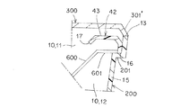
(実施形態4の構成の説明)
図6は、この発明にかかる車両用灯具の実施形態4を示す。以下、この実施形態4にかかる車両用灯具について説明する。図中、図1〜図5と同符号は、同一のものを示す。
(Description of Configuration of Embodiment 4)
FIG. 6 shows
この実施形態4にかかる車両用灯具は、前記の実施形態1にかかる車両用灯具1および前記の実施形態3にかかる車両用灯具101のホルダ5を除いた構造である。すなわち、ランプレンズ300の開口端部301’が、ホルダ5を介さずに、ランプハウジング200の一端13に、直接固定されているものである。
The vehicular lamp according to the fourth embodiment has a structure excluding the
ランプハウジング200の4側面15の途中には、水平段部201が設けられている。一方、インナーパネル42には、水平板部43が設けられている。また、分割部材600にも、水平板部601が設けられている。インナーパネル42の一端16および分割部材600の水平板部601が、ランプハウジング200の水平段部201に固定されている。
A
(実施形態4の作用および効果の説明)
この実施形態4にかかる車両用灯具は、以上のごとき構成からなるので、前記の実施形態1にかかる車両用灯具1および前記の実施形態3にかかる車両用灯具101とほぼ同様の作用および効果を達成することができる。
(Explanation of action and effect of Embodiment 4)
Since the vehicular lamp according to the fourth embodiment is configured as described above, the
(実施形態5の構成の説明)
図7は、この発明にかかる車両用灯具の実施形態5を示す。以下、この実施形態5にかかる車両用灯具について説明する。図中、図1〜図6と同符号は、同一のものを示す。
(Description of Configuration of Embodiment 5)
FIG. 7 shows
この実施形態5にかかる車両用灯具は、前記の実施形態2にかかる車両用灯具100のホルダ5を除いた構造である。すなわち、ランプレンズ300の開口端部301’が、ホルダ5を介さずに、ランプハウジング200の一端13に、直接固定されているものである。
The vehicular lamp according to the fifth embodiment has a structure excluding the
ランプハウジング200の4側面15の途中には、水平段部201が設けられている。インナーパネル400の一端側板部401が、ランプハウジング200の水平段部201に固定されている。
A
(実施形態5の作用および効果の説明)
この実施形態5にかかる車両用灯具は、以上のごとき構成からなるので、前記の実施形態2にかかる車両用灯具100とほぼ同様の作用および効果を達成することができる。
(Explanation of action and effect of embodiment 5)
Since the vehicular lamp according to the fifth embodiment is configured as described above, it is possible to achieve substantially the same operations and effects as the
(実施形態1、2、3、4、5以外の例の説明)
なお、前記の実施形態1、2、3、4、5においては、リアコンビネーションランプのテールランプあるいはストップランプについて説明するものである。ところが、この発明においては、リアコンビネーションランプのテールランプあるいはストップランプ以外の車両用灯具、たとえば、フロントコンビネーションランプのデイタイムランニングランプやクリアランスランプやターンシグナルランプ、リアコンビネーションランプのターンシグナルランプやクリアランスランプなどにも適用することができる。
(Description of examples other than
In the first, second, third, fourth, and fifth embodiments, the tail lamp or stop lamp of the rear combination lamp will be described. However, in the present invention, a vehicle lamp other than the rear combination lamp tail lamp or stop lamp, for example, a front combination lamp daytime running lamp, clearance lamp, turn signal lamp, rear combination lamp turn signal lamp, clearance lamp, etc. It can also be applied to.
また、前記の実施形態1においては、図2、図3に示すように、車両用灯具1の正面視形状が四角形状をなすものである。ところが、この発明においては、車両用灯具1、100の正面視形状が四角形状以外の形状、たとえば、三角形状、長方形状、五角形以上の多角形状、円形状、楕円形状、長円形状などであっても良い。ここで、車両用灯具1、100の正面視形状が四角形状以外の形状に変わった場合、この場合においては、分割部材6や第2導光部材28などの数が変化する場合がある。
Moreover, in the said
1、100、101 車両用灯具
2、200 ランプハウジング
3、300 ランプレンズ
4、400、41、42 インナーパネル
5 ホルダ
6、600 分割部材
7、700、71 第1ランプユニット
8、800、81 第2ランプユニット
9、900 光不透過部材
10 灯室
11 第1灯室
12 第2灯室
13 一端(開口端部)
14 他端(閉塞端部)
15 4側面(閉塞側面部)
16 一端(開口端部)
17 4側面(開口側面部)
18 他端(閉塞端部)
19 一端側の開口部(開口一端)
20 他端側の開口部(開口他端)
21 共通基板
22 第1光源
23 第1導光部材
24、241 第1入射面
25 第1発光面
26 虚像
27 第2光源
28 第2導光部材
29 第2入射面
201 水平段部
30 第2発光面
31 切込部
301’ 開口端部
43 水平板部
401 一端側板部
402 他端側板部
403 一端側開口部
404 他端側開口部
601 水平板部
701 第1基板
702 第1レンズ
703 第1発光面
801 第2基板
802 第2導光部材
803 第2入射面
804 第2発光面
32 第1全反射面
33 第2全反射面
181 第1リフレクタ
291 第1反射面
281 第2リフレクタ
301 第2発光面としての第2反射面
Z 光軸
DESCRIPTION OF SYMBOLS 1,100,101 Vehicle lamp 2,200 Lamp housing 3,300 Lamp lens 4,400,41,42
14 Other end (closed end)
15 4 side (closed side)
16 One end (open end)
17 4 side (opening side)
18 Other end (closed end)
19 Opening on one end (one opening)
20 Opening at the other end (opening other end)
DESCRIPTION OF
Claims (4)
前記灯室内を第1灯室と前記第1灯室より暗い第2灯室とに分割し、前記第1灯室側の光を反射させ、かつ、前記第2灯室側の光を透過させる分割部材と、
前記第1灯室内に配置されていて、前記分割部材を介して前記第2灯室内に虚像として映り込む第1発光面と、
前記第2灯室内に、前記第1発光面の虚像よりも前記ランプレンズ側に配置されている第2発光面と、
を備えることを特徴とする車両用灯具。 A lamp housing and a lamp lens that partition the lamp chamber;
The lamp chamber is divided into a first lamp chamber and a second lamp chamber that is darker than the first lamp chamber, reflects light on the first lamp chamber side, and transmits light on the second lamp chamber side. A split member;
A first light emitting surface disposed in the first lamp chamber and reflected as a virtual image in the second lamp chamber through the dividing member;
A second light emitting surface disposed in the second lamp chamber on the lamp lens side from a virtual image of the first light emitting surface;
A vehicular lamp characterized by comprising:
前記第1発光面は、前記第1発光面の虚像が前記切込部に対応する位置に位置するように配置されている、
ことを特徴とする請求項1に記載の車両用灯具。 The second light emitting surface is provided with a notch,
The first light emitting surface is disposed such that a virtual image of the first light emitting surface is located at a position corresponding to the cut portion.
The vehicular lamp according to claim 1.
ことを特徴とする請求項1または2に記載の車両用灯具。 The first light emitting surface and the second light emitting surface are provided with optical elements having different light emission states, respectively.
The vehicular lamp according to claim 1 or 2.
ことを特徴とする請求項1〜3のいずれか1項に記載の車両用灯具。 A light-impermeable member that covers at least a part of the first light emitting surface so as not to be seen from the lamp lens side is disposed in the first lamp chamber.
The vehicular lamp according to any one of claims 1 to 3.
Priority Applications (1)
| Application Number | Priority Date | Filing Date | Title |
|---|---|---|---|
| JP2014146780A JP6340975B2 (en) | 2014-07-17 | 2014-07-17 | Vehicle lighting |
Applications Claiming Priority (1)
| Application Number | Priority Date | Filing Date | Title |
|---|---|---|---|
| JP2014146780A JP6340975B2 (en) | 2014-07-17 | 2014-07-17 | Vehicle lighting |
Publications (2)
| Publication Number | Publication Date |
|---|---|
| JP2016024899A JP2016024899A (en) | 2016-02-08 |
| JP6340975B2 true JP6340975B2 (en) | 2018-06-13 |
Family
ID=55271517
Family Applications (1)
| Application Number | Title | Priority Date | Filing Date |
|---|---|---|---|
| JP2014146780A Active JP6340975B2 (en) | 2014-07-17 | 2014-07-17 | Vehicle lighting |
Country Status (1)
| Country | Link |
|---|---|
| JP (1) | JP6340975B2 (en) |
Families Citing this family (1)
| Publication number | Priority date | Publication date | Assignee | Title |
|---|---|---|---|---|
| JP7281883B2 (en) * | 2018-08-10 | 2023-05-26 | 株式会社小糸製作所 | vehicle lamp |
Family Cites Families (3)
| Publication number | Priority date | Publication date | Assignee | Title |
|---|---|---|---|---|
| JPS59115509U (en) * | 1983-01-26 | 1984-08-04 | トヨタ自動車株式会社 | lamp structure |
| JP4751179B2 (en) * | 2005-10-31 | 2011-08-17 | 矢崎総業株式会社 | Display device |
| KR102224459B1 (en) * | 2014-02-05 | 2021-03-08 | 엘지이노텍 주식회사 | Geometric Lighting Device and Vehicle Lighting Device Using the Same |
-
2014
- 2014-07-17 JP JP2014146780A patent/JP6340975B2/en active Active
Also Published As
| Publication number | Publication date |
|---|---|
| JP2016024899A (en) | 2016-02-08 |
Similar Documents
| Publication | Publication Date | Title |
|---|---|---|
| JP4930787B2 (en) | VEHICLE LIGHT AND LIGHT GUIDE LENS USED FOR VEHICLE LIGHT | |
| US10598336B2 (en) | Light device for motor vehicles | |
| JP7163710B2 (en) | Vehicle optical device | |
| JP6264789B2 (en) | Vehicle lighting | |
| JP6361248B2 (en) | Vehicle lighting | |
| CN112840158B (en) | Lighting device for vehicle | |
| US20160138773A1 (en) | Vehicle combination lamp | |
| JP2016046120A (en) | Vehicular lighting fixture | |
| KR101684117B1 (en) | Mood lamp for vehicle | |
| JP6221589B2 (en) | Vehicle lighting | |
| JP2014154524A (en) | Lighting fixture | |
| JP6419444B2 (en) | A lamp that represents the light tunnel | |
| US20230358387A1 (en) | Vehicle lighting fixture | |
| JP6497054B2 (en) | Vehicle light guide member, vehicle lamp | |
| KR102145189B1 (en) | Lamp for vehicle | |
| JP6340975B2 (en) | Vehicle lighting | |
| JP6769135B2 (en) | Vehicle rear-viewing device equipped with vehicle lighting equipment and vehicle lighting equipment | |
| JP2015193287A (en) | Vehicle signal lighting appliance | |
| JP6823439B2 (en) | Lenses and vehicle lamps with wraparound light guide | |
| JP5278209B2 (en) | Vehicle lighting | |
| JP6221117B2 (en) | Vehicle lighting | |
| JP6035901B2 (en) | Vehicle lighting | |
| JP6838327B2 (en) | Vehicle optics and vehicle lamps with vehicle optics | |
| JP2019153413A (en) | Vehicular lighting fixture | |
| JP2016100256A (en) | Vehicle lamp fitting |
Legal Events
| Date | Code | Title | Description |
|---|---|---|---|
| A621 | Written request for application examination |
Free format text: JAPANESE INTERMEDIATE CODE: A621 Effective date: 20170718 |
|
| A977 | Report on retrieval |
Free format text: JAPANESE INTERMEDIATE CODE: A971007 Effective date: 20180322 |
|
| TRDD | Decision of grant or rejection written | ||
| A01 | Written decision to grant a patent or to grant a registration (utility model) |
Free format text: JAPANESE INTERMEDIATE CODE: A01 Effective date: 20180417 |
|
| A61 | First payment of annual fees (during grant procedure) |
Free format text: JAPANESE INTERMEDIATE CODE: A61 Effective date: 20180430 |
|
| R150 | Certificate of patent or registration of utility model |
Ref document number: 6340975 Country of ref document: JP Free format text: JAPANESE INTERMEDIATE CODE: R150 |
|
| R250 | Receipt of annual fees |
Free format text: JAPANESE INTERMEDIATE CODE: R250 |
|
| R250 | Receipt of annual fees |
Free format text: JAPANESE INTERMEDIATE CODE: R250 |
|
| R250 | Receipt of annual fees |
Free format text: JAPANESE INTERMEDIATE CODE: R250 |