EP3159704A1 - Messkette für eine elektronische signalschaltung - Google Patents
Messkette für eine elektronische signalschaltung Download PDFInfo
- Publication number
- EP3159704A1 EP3159704A1 EP16195121.5A EP16195121A EP3159704A1 EP 3159704 A1 EP3159704 A1 EP 3159704A1 EP 16195121 A EP16195121 A EP 16195121A EP 3159704 A1 EP3159704 A1 EP 3159704A1
- Authority
- EP
- European Patent Office
- Prior art keywords
- measuring
- resistor
- test
- chain
- switch
- Prior art date
- Legal status (The legal status is an assumption and is not a legal conclusion. Google has not performed a legal analysis and makes no representation as to the accuracy of the status listed.)
- Granted
Links
- 230000011664 signaling Effects 0.000 title claims abstract description 35
- 238000012360 testing method Methods 0.000 claims abstract description 92
- 238000005259 measurement Methods 0.000 claims abstract description 38
- 238000012797 qualification Methods 0.000 claims abstract description 4
- 230000000295 complement effect Effects 0.000 claims description 2
- 230000003111 delayed effect Effects 0.000 claims description 2
- 239000003990 capacitor Substances 0.000 description 7
- 238000010586 diagram Methods 0.000 description 3
- 238000009434 installation Methods 0.000 description 3
- 238000004804 winding Methods 0.000 description 3
- 230000004913 activation Effects 0.000 description 2
- 238000006243 chemical reaction Methods 0.000 description 2
- 235000021183 entrée Nutrition 0.000 description 2
- 230000005284 excitation Effects 0.000 description 2
- 241001080024 Telles Species 0.000 description 1
- 230000002950 deficient Effects 0.000 description 1
- 238000011156 evaluation Methods 0.000 description 1
- 230000005669 field effect Effects 0.000 description 1
- 238000002347 injection Methods 0.000 description 1
- 239000007924 injection Substances 0.000 description 1
- 238000012545 processing Methods 0.000 description 1
- 238000012163 sequencing technique Methods 0.000 description 1
- 230000003068 static effect Effects 0.000 description 1
- 230000001131 transforming effect Effects 0.000 description 1
- 230000000007 visual effect Effects 0.000 description 1
Images

Classifications
-
- G—PHYSICS
- G01—MEASURING; TESTING
- G01R—MEASURING ELECTRIC VARIABLES; MEASURING MAGNETIC VARIABLES
- G01R1/00—Details of instruments or arrangements of the types included in groups G01R5/00 - G01R13/00 and G01R31/00
- G01R1/20—Modifications of basic electric elements for use in electric measuring instruments; Structural combinations of such elements with such instruments
- G01R1/203—Resistors used for electric measuring, e.g. decade resistors standards, resistors for comparators, series resistors, shunts
-
- G—PHYSICS
- G01—MEASURING; TESTING
- G01D—MEASURING NOT SPECIALLY ADAPTED FOR A SPECIFIC VARIABLE; ARRANGEMENTS FOR MEASURING TWO OR MORE VARIABLES NOT COVERED IN A SINGLE OTHER SUBCLASS; TARIFF METERING APPARATUS; MEASURING OR TESTING NOT OTHERWISE PROVIDED FOR
- G01D21/00—Measuring or testing not otherwise provided for
-
- G—PHYSICS
- G01—MEASURING; TESTING
- G01R—MEASURING ELECTRIC VARIABLES; MEASURING MAGNETIC VARIABLES
- G01R1/00—Details of instruments or arrangements of the types included in groups G01R5/00 - G01R13/00 and G01R31/00
- G01R1/20—Modifications of basic electric elements for use in electric measuring instruments; Structural combinations of such elements with such instruments
-
- G—PHYSICS
- G01—MEASURING; TESTING
- G01R—MEASURING ELECTRIC VARIABLES; MEASURING MAGNETIC VARIABLES
- G01R35/00—Testing or calibrating of apparatus covered by the other groups of this subclass
-
- G—PHYSICS
- G01—MEASURING; TESTING
- G01R—MEASURING ELECTRIC VARIABLES; MEASURING MAGNETIC VARIABLES
- G01R35/00—Testing or calibrating of apparatus covered by the other groups of this subclass
- G01R35/02—Testing or calibrating of apparatus covered by the other groups of this subclass of auxiliary devices, e.g. of instrument transformers according to prescribed transformation ratio, phase angle, or wattage rating
-
- G—PHYSICS
- G01—MEASURING; TESTING
- G01R—MEASURING ELECTRIC VARIABLES; MEASURING MAGNETIC VARIABLES
- G01R31/00—Arrangements for testing electric properties; Arrangements for locating electric faults; Arrangements for electrical testing characterised by what is being tested not provided for elsewhere
- G01R31/005—Testing of electric installations on transport means
- G01R31/008—Testing of electric installations on transport means on air- or spacecraft, railway rolling stock or sea-going vessels
Definitions
- An electrical signaling circuit is a circuit whose role is to provide information, for example visual, on the operating status of an installation.
- such a signaling circuit comprises a light which is lit when the installation is in a first state and off when the installation is in a second state.
- the signaling circuit may provide erroneous information in the event of failure of some of its components, which is why it is known to provide a measurement chain on the signaling circuit to check that it is functioning properly.
- the measuring chain comprises a current sensor for checking the flow of a current in the signaling circuit.
- the current sensor consists of a resistor and a voltage measuring device connected across the resistor.
- the voltage drop measured between the terminals of the resistor is proportional to the current to be determined (Ohm's law).
- An operation test is, for example, carried out by means of switches which impose, at the terminals of the resistor, a test signal instead of the measured signal. These switches connect the resistor to a circuit providing a known test signal instead of the signaling circuit. The voltage drop across the resistor is measured. If the measured value corresponds to the predicted value for the test signal, the resistor is considered to work properly.
- Such a test of a sensor is known and for example described by WO 2004/062170 A2 .
- the signaling circuit is inoperative, since if the switches provide the connection of the resistor to the circuit providing a test signal, the signaling circuit is open and thus stopped. This is annoying for some systems. This is why, generally, the tests are carried out only during the initialization of the signaling circuit and not during its operation.
- the purpose of the invention is to make it possible to test the operation of the current sensor, without a reinitialization of the circuit being necessary.
- the possibility of a permanent connection of the measuring resistor with the signaling circuit makes it possible to operate the signaling circuit independently of the tests carried out by the measuring chain and the test resistor having a resistance much greater than the measurement resistance, most of the current of the signaling circuit passes through the measuring resistor.
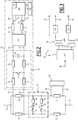
- the signaling circuit 4 is able to give information on the state of operation of the main electrical circuit 2.
- the main electrical circuit 2 is clean, for example, to operate a motor for external use. It comprises, connected in series, a source of energy 6, a motor 8 and a switch 10.
- the energy source 6 is able to provide, for example, a voltage of 2 kV of alternating current to supply the motor 8.
- the signaling circuit 4 includes, connected in series, a power source 12, a switch 14, a lamp 16 forming a charge and a measuring chain 18 of the current flowing in the circuit 4.
- the energy source 12 is, for example, able to provide a current of 24 volts of direct current or 110 volts of alternating current.
- the switch 14 is mechanically coupled to the switch 10 of the main electrical circuit so that the two switches 10, 14 are always in the same state, open or closed. Thus, if the main electrical circuit 2 is closed / open, the signaling circuit 4 is also closed / open and vice versa. With this structure, the signaling circuit 4 is therefore able to give information on the state of the switch 10.
- the measuring chain 18 is connected to the signaling circuit 4 by an input 20 and an output 22.
- the measuring chain 18 is represented alone on the figure 2 . It comprises two measurement branches connected in parallel between the input 20 and the output 22. Each branch has, respectively, in series, a measurement resistor 30, 31 and a balancing resistor 32, 33 respectively.
- a pulse test exciter 34 is connected between the midpoints of the two parallel branches, i.e. between the measurement resistor 30, 31 and the balancing resistor 32, 33 respectively. It consists of two excitation branches connected in parallel between the midpoints.
- Each excitation branch comprises respectively a controllable switch 36, 37 to initiate the pulse test, a voltage source 38, 39 able to provide a current pulse and a test resistor 40, 41 able to limit the maximum value of the current pulse.
- the voltage sources 38 and 39 are preferably capable of supplying a voltage, which is opposite to each other.
- the switches 36, 37 are formed for example of MOSFET transistors.
- the values of the measuring and balancing resistors 30 to 33 are small compared to the values of the test resistors 40 and 41.
- the measuring and balancing resistors 30 to 33 even have a resistance value of 0.1 Ohm, the test resistor 40 has a resistance value of 33 Ohm and the test resistor 41 has a resistance value. 47 Ohm.
- the ratio between the values of each test resistor 40, 41 and the values of each measuring resistor 30, 31 and / or balancing 32, 33 is greater than 10, preferably 100 and more preferably higher at 300.
- the current flowing from the input 20 to the output 22 is determined by two acquisition chains 42 connected respectively to the terminals of the measurement resistor 30. by lines 44 and 45 and across the measuring resistor 31 by lines 46 and 47.
- the two acquisition chains 42 have identical components and have the same behavior as described below.
- Each acquisition chain 42 is able to measure the voltage between the terminals of the measurement resistor 30, 31, which is proportional to the current flowing through the measurement resistor 30, 31.
- Each acquisition system 42 comprises, at the input, a quadrupole of controllable shunt 48 connected at the input terminals of the resistor 30, 31 by lines 44, 45 and 46, 47 respectively.
- the two other terminals of the shunt quadrupole forming an output are connected to a converter 50 of the acquisition system 42 by input lines 52, 53.
- the converter 50 forming a means for measuring the voltage across the measuring resistor 30, 31 is suitable for converting an analog signal into a digital signal. It includes a sigma delta encoder known per se followed by a decoder.
- the converter 50 comprises two output lines 54, 55 each connected through a resistor 56, 57 limiting the current to the inputs 58, 59 of a computer 60.
- the computer 60 is able to compare the voltages measured between the two terminals of the measurement resistor 30, 31 with reference values in the two states of the switches 36, 37.
- the computer 60 is formed of an FPGA.
- the computer 60 is able to send the result of the comparison made by at least one output line 64 to qualifying means 66 formed for example of a screen.
- the qualification means 66 are able to transmit the signal to a connected computer for further processing.
- the controllable shunt quadrupole 48 has two parallel branches each having a test resistor 70, 71 and a resistor 72, 73 in series.
- a link branch having the controllable switch 74 connects the midpoints of the two parallel branches between the resistors 70 and 72 and the resistors 71 and 73.
- a capacitor 76 connects the input lines 52, 53 to which the resistors 72, 73 are connected.
- test resistors 70 and 71 are for example 22 Ohm.
- the value of the resistors 72 and 73 is for example 215 Ohm.
- the ratio between the values of the test resistor 70, 71 and the measurement resistor 30, 31 and / or balancing 32, 33 is greater than 100.
- the switch 74 is, for example, a field effect transistor (FET).
- FET field effect transistor
- the computer 60 comprises for each input line 58, 59 respectively a line 77, 78 return.
- the computer is able to emit a test signal in each return line 77, 78.
- the comparison means 60 are able to carry out a self-test operation described later.
- the computer 60 includes a control unit 79 able to send commands in the measurement chain 18, and in particular to produce the test signals on the lines 77 and 78 and to control the switch 74.
- the control unit 79 is also clean, according to a sequencing which will be described below, to control the state of the switches 36, 37 and to control the charging of the capacitors 38, 39 from the control circuit 80 of the exciter 34 shown on the figure 3 .
- the control circuit 80 comprises a power chopper 81 which is able to jointly control the switch 36, 37 and to charge the capacitor 38, 39.
- a control circuit 80 as described with reference to FIG. figure 3 is implemented for each branch of the exciter, that is to say for each switch 36, respectively 37 and capacitor 38, respectively 39.
- Each chopper 81 is powered by a power supply line 82 and controlled by a control line 84 connected to the control unit 79.
- the chopper 81 is for example a controlled transistor bridge capable of transforming a direct supply current received on the supply line 82 into a high-frequency current output.
- the control of the transistors is ensured by the control unit 79.
- the output of the chopper 81 is connected to the primary of a transformer 86 with double winding in series.
- the transformer 86 comprises two independent secondary windings, each connected to an input of a rectifier 90 and 91.
- the output of the rectifiers 90 and 91 is respectively connected by load lines 92, 93 to the terminals of a capacitor 38, 39. This link allows charging of the voltage source 38, 39 with a rectified current.
- a control line 88 is stitched on the output of one of the secondary windings. This line is connected to the switch 36, 37 through a high-pass filter RC forming a retarder and a rectifier.
- the filter and the rectifier are such that at the expiration of the time constant of the self-timer, while a high-frequency signal is provided on the control line 88, a DC supplied by the rectifier provides the control of the switch 36, 37 to put it in a passing state.
- This time constant is chosen sufficiently large to allow the charge of the capacitor 38, 39 before the switch 36, 37 becomes passing.
- the control unit 79 is able to separately control the switches 36, 37 in addition to the switch 74.
- the switch 14 If the switch 14 is closed and the energy source 12 supplies a current, the current passes through the lamp 16 and the measurement chain 18. In the measurement chain 18, the current passes halfway through the measurement resistors. 30 and balancing 32 and half by the measuring resistors 31 and balancing 33, the values of the resistors 30, 32 and 31, 33 being equal.
- the switches 36, 37 and 74 are open and the acquisition chain 42 provides on the display 66 a value of the current flowing in the circuit 4. This value is obtained from the voltage measured at the terminals of the resistance 30, 31.
- the measurement chain 18 is preferably suitable for carrying out three types of tests under the control of the control unit 79. According to the embodiments, the measurement chain 18 comprises one or more of the following tests.
- the aim of the pulse test is to verify the operation of the measuring resistor 30, 31, of the converter 50 and of the comparison means 60. These components are dedicated to the acquisition of the current and the conversion into a digital value.
- control unit 79 controls the charging of a voltage source for example 38 by means of the control circuit 80 of the figure 3 .
- the charging is carried out under the control of the control unit 79 which controls the chopper 80 to power the transformer 86 which itself feeds the rectifiers 90 and 91.
- the direct current thus produced charges the voltage sources 38 and 39.
- the switch 36 is closed while the signaling circuit 4 is still connected and in operation.
- the closing of the switch 36 is controlled by the high frequency signal transmitted on the line 88 and produced by the chopper 81 under the control of the control unit 79.
- This implementation brings the advantage of a reduction of the insulating components, since the control to turn on the switch 36, 37 is transmitted by the same electrical circuit as that ensuring the charging of the voltage source 38, 39.
- the total current passing the measuring resistor 30, 31 changes.
- the current injected by the voltage source 38 follows an evanescent exponential curve.
- the voltage across the resistor 30, 31 is acquired by the acquisition chain 42.
- the comparison means 60 compare a reference acquired voltage curve for a resistor operating correctly in the absence of current flowing between the input 20 and output 22 and the voltage curve acquired during the test, from which the last value of measured voltage across the measuring resistor 30, 31 and obtained at the output of the converter 50.
- the reference voltage curve for correct operation is stored in the comparison means 60.
- the comparison means 60 consider the measurement resistor 30 to function correctly and the result is displayed on the screen 66. Otherwise, an error message is displayed on the screen 66.
- the switch 36 is open and the switch 37 is closed.
- a current pulse is then injected similarly into the measurement chain 18, but with a reverse direction current at the first part of the test.
- the same comparisons are made by the comparison means 60 with reference voltage curves that are specific to the voltage source 37. This second part of the pulse test is implemented to ensure that the current acquisition works in both directions. current flow.
- the purpose of the offset test is to calibrate the converter input 50 and to ensure that there is no stored data if there is a static current in the measurement chain 18, because the source of energy 12 provides a direct current, for example.
- the test is initiated by the closing of the switch 74 under the control of the control unit 79 while the current flows or not in the circuit 4.
- the comparison means 60 measure, after a conversion of the values into digital by the converter 50, the potential difference between the lines 52 and 53 and compare it with the predicted value, which is normally zero.
- test resistors 70 and 71 of high value with respect to the resistors 30, 31 are able to guarantee a circulation of the bulk of the current towards the measurement resistor 30.
- This test is also performed independently of the state of the signaling circuit 4.
- the offset test is performed after execution of the pulse test.
- the purpose of the return test is to test the operation of the comparison means 60, for example the FPGA.
- the high level test signal overrides the measured signal, which comes from the converter 50.
- the comparison means detects the injected test signal and indicates normal operation on the screen 66. Otherwise nothing is displayed on the screen 66 .
- This test is also independent of the state of the signaling circuit 4. If the signal detected by the FPGA does not correspond to the predicted signal, the FPGA is deficient.
- the set of switches 10 and 14 is a relay.
- the signaling circuit 4 is a control circuit, which is able to control the relay.
- the relay is able to interrupt or close the main electrical circuit 2, which is a charging circuit in this variant.
- the pulse test trigger 34 comprises only one branch with a switch 36, a voltage source 38 and a resistor 40. In this variant, the pulse test trigger 34 is therefore not than able to provide a current pulse in one direction.
- additional information is transferred through the output line 64 to the qualifying means 66, such as the power supply type of the power source 12 or corresponding values of a voltage or current. .
Landscapes
- Physics & Mathematics (AREA)
- General Physics & Mathematics (AREA)
- Engineering & Computer Science (AREA)
- Power Engineering (AREA)
- Measurement Of Current Or Voltage (AREA)
- Measurement Of Resistance Or Impedance (AREA)
- Testing Electric Properties And Detecting Electric Faults (AREA)
Applications Claiming Priority (1)
| Application Number | Priority Date | Filing Date | Title |
|---|---|---|---|
| FR1560166A FR3042878B1 (fr) | 2015-10-23 | 2015-10-23 | Chaine de mesure pour un circuit electronique de signalisation |
Publications (2)
| Publication Number | Publication Date |
|---|---|
| EP3159704A1 true EP3159704A1 (de) | 2017-04-26 |
| EP3159704B1 EP3159704B1 (de) | 2021-06-09 |
Family
ID=54783898
Family Applications (1)
| Application Number | Title | Priority Date | Filing Date |
|---|---|---|---|
| EP16195121.5A Active EP3159704B1 (de) | 2015-10-23 | 2016-10-21 | Messkette für eine elektronische signalschaltung |
Country Status (3)
| Country | Link |
|---|---|
| EP (1) | EP3159704B1 (de) |
| FR (1) | FR3042878B1 (de) |
| RU (1) | RU2718695C2 (de) |
Citations (4)
| Publication number | Priority date | Publication date | Assignee | Title |
|---|---|---|---|---|
| WO2004062170A2 (en) | 2002-12-31 | 2004-07-22 | Rosemount, Inc. | Field transmitter with diagnostic self-test mode |
| DE102012006269A1 (de) * | 2011-03-29 | 2012-10-04 | Continental Teves Ag & Co. Ohg | Stromsensor |
| US20130154672A1 (en) * | 2011-12-16 | 2013-06-20 | Lear Corporation | Method and System for Battery Current Measurement Calibration |
| EP2752672A1 (de) * | 2013-01-04 | 2014-07-09 | Linear Technology Corporation | Verfahren und System zum Messen des Widerstandes einer resistiven Struktur |
Family Cites Families (5)
| Publication number | Priority date | Publication date | Assignee | Title |
|---|---|---|---|---|
| FR2603113B1 (fr) * | 1986-08-22 | 1988-11-18 | Catu Ets | Systeme de verification du fonctionnement d'un controleur de tension |
| US7788055B2 (en) * | 2006-07-14 | 2010-08-31 | Square D Company | Method and system of calibrating sensing components in a circuit breaker system |
| US7928744B2 (en) * | 2008-12-02 | 2011-04-19 | Analog Devices, Inc. | Monitoring circuit having a self test function |
| US8613896B2 (en) * | 2010-05-19 | 2013-12-24 | Shell Oil Company | Process for removing nitrous oxide from a gas stream |
| RU2460080C1 (ru) * | 2011-02-25 | 2012-08-27 | Федеральное государственное унитарное предприятие "Центральный научно-исследовательский институт судовой электротехники и технологии" (ФГУП "ЦНИИ СЭТ") | Устройство измерения и контроля эквивалентного сопротивления изоляции изолированных от земли силовых электрических сетей постоянного тока под рабочим напряжением |
-
2015
- 2015-10-23 FR FR1560166A patent/FR3042878B1/fr not_active Expired - Fee Related
-
2016
- 2016-10-21 RU RU2016141478A patent/RU2718695C2/ru active
- 2016-10-21 EP EP16195121.5A patent/EP3159704B1/de active Active
Patent Citations (4)
| Publication number | Priority date | Publication date | Assignee | Title |
|---|---|---|---|---|
| WO2004062170A2 (en) | 2002-12-31 | 2004-07-22 | Rosemount, Inc. | Field transmitter with diagnostic self-test mode |
| DE102012006269A1 (de) * | 2011-03-29 | 2012-10-04 | Continental Teves Ag & Co. Ohg | Stromsensor |
| US20130154672A1 (en) * | 2011-12-16 | 2013-06-20 | Lear Corporation | Method and System for Battery Current Measurement Calibration |
| EP2752672A1 (de) * | 2013-01-04 | 2014-07-09 | Linear Technology Corporation | Verfahren und System zum Messen des Widerstandes einer resistiven Struktur |
Also Published As
| Publication number | Publication date |
|---|---|
| EP3159704B1 (de) | 2021-06-09 |
| FR3042878A1 (fr) | 2017-04-28 |
| RU2016141478A (ru) | 2018-04-24 |
| RU2016141478A3 (de) | 2020-02-18 |
| FR3042878B1 (fr) | 2018-01-12 |
| RU2718695C2 (ru) | 2020-04-13 |
Similar Documents
| Publication | Publication Date | Title |
|---|---|---|
| FR3019303B1 (fr) | Dispositif de mesure d'au moins une grandeur physique d'une installation electrique | |
| WO1987000129A1 (fr) | Alimentation en energie electrique de circuits sur la roue pour un dispositif de surveillance des pneumatiques | |
| CH669057A5 (fr) | Installation de surveillance et d'alarme. | |
| CA2315896C (fr) | Circuit electronique de surveillance de tension electrique | |
| FR2884982A1 (fr) | Dispositif de commande pour generateur automobile | |
| EP0809342B1 (de) | Anordnung zur Regelung der Ladung einer modularen Einheit von elektrochemischen Zellen, die in Reihe geschaltet sind und entsprechendes Modul zur Messung der Zellen | |
| EP3462187A1 (de) | Spannungspräsenz-anzeigesystem in einem hochspannungsnetz | |
| EP3159704B1 (de) | Messkette für eine elektronische signalschaltung | |
| EP2503575B1 (de) | Diagnoseverfahren und -vorrichtung eines Aktuators, und mit einer solchen Vorrichtung ausgestattetes Aktuator | |
| FR2876799A1 (fr) | Detection du passage par zero d'une tension alternative | |
| FR3030767A1 (fr) | Procede et dispositif de diagnostic d’un dispositif de gestion de l’energie electrique | |
| FR2932917A1 (fr) | Installation de securite a auto-diagnostic perfectionne. | |
| FR3067514B1 (fr) | Liaison electrique comprenant un dispositif de protection electrique - test d'integrite | |
| EP3938792B1 (de) | Elektrische anlage mit einem überwachungsmodul | |
| FR2540634A1 (fr) | Procede et appareil de detection de composants electriques non lineaires | |
| EP2991180B1 (de) | Elektrische trennschaltung für elektrische vorrichtungen, die in einem netz verbunden sind, steuerverfahren einer solchen schaltung | |
| FR2628591A1 (fr) | Procede de declenchement d'un electrificateur de cloture et son dispositif de mise en oeuvre | |
| EP0617292B1 (de) | System zur ständigen Überwachung der elektrischen Leitfähigkeit eines Wechselstromnetzes | |
| FR2870996A1 (fr) | Protection de circuit electrique en mode veille pour vehicule | |
| FR2719123A1 (fr) | Dispositif de détection de la variation non transitoire d'une tension d'alimentation. | |
| EP3938793B1 (de) | Elektrische anlage mit einem überwachungsmodul | |
| FR2963855A1 (fr) | Dispositif securise pour controler un chargeur de batterie de vehicule electrique | |
| FR2827676A1 (fr) | Procede de diagnostic d'etage de puissance discret par des entrees numeriques | |
| FR2827675A1 (fr) | Dispositif et procede de surveillance de reseau electrique, et installation comportant un tel dispositif | |
| FR2830692A1 (fr) | Declencheur electronique comportant un dispositif de test des capteurs de courant |
Legal Events
| Date | Code | Title | Description |
|---|---|---|---|
| PUAI | Public reference made under article 153(3) epc to a published international application that has entered the european phase |
Free format text: ORIGINAL CODE: 0009012 |
|
| STAA | Information on the status of an ep patent application or granted ep patent |
Free format text: STATUS: THE APPLICATION HAS BEEN PUBLISHED |
|
| AK | Designated contracting states |
Kind code of ref document: A1 Designated state(s): AL AT BE BG CH CY CZ DE DK EE ES FI FR GB GR HR HU IE IS IT LI LT LU LV MC MK MT NL NO PL PT RO RS SE SI SK SM TR |
|
| AX | Request for extension of the european patent |
Extension state: BA ME |
|
| STAA | Information on the status of an ep patent application or granted ep patent |
Free format text: STATUS: REQUEST FOR EXAMINATION WAS MADE |
|
| 17P | Request for examination filed |
Effective date: 20170727 |
|
| RBV | Designated contracting states (corrected) |
Designated state(s): AL AT BE BG CH CY CZ DE DK EE ES FI FR GB GR HR HU IE IS IT LI LT LU LV MC MK MT NL NO PL PT RO RS SE SI SK SM TR |
|
| STAA | Information on the status of an ep patent application or granted ep patent |
Free format text: STATUS: EXAMINATION IS IN PROGRESS |
|
| 17Q | First examination report despatched |
Effective date: 20200327 |
|
| GRAP | Despatch of communication of intention to grant a patent |
Free format text: ORIGINAL CODE: EPIDOSNIGR1 |
|
| STAA | Information on the status of an ep patent application or granted ep patent |
Free format text: STATUS: GRANT OF PATENT IS INTENDED |
|
| INTG | Intention to grant announced |
Effective date: 20210128 |
|
| GRAS | Grant fee paid |
Free format text: ORIGINAL CODE: EPIDOSNIGR3 |
|
| GRAA | (expected) grant |
Free format text: ORIGINAL CODE: 0009210 |
|
| STAA | Information on the status of an ep patent application or granted ep patent |
Free format text: STATUS: THE PATENT HAS BEEN GRANTED |
|
| AK | Designated contracting states |
Kind code of ref document: B1 Designated state(s): AL AT BE BG CH CY CZ DE DK EE ES FI FR GB GR HR HU IE IS IT LI LT LU LV MC MK MT NL NO PL PT RO RS SE SI SK SM TR |
|
| REG | Reference to a national code |
Ref country code: GB Ref legal event code: FG4D Free format text: NOT ENGLISH |
|
| REG | Reference to a national code |
Ref country code: CH Ref legal event code: EP Ref country code: AT Ref legal event code: REF Ref document number: 1400942 Country of ref document: AT Kind code of ref document: T Effective date: 20210615 |
|
| REG | Reference to a national code |
Ref country code: DE Ref legal event code: R096 Ref document number: 602016059067 Country of ref document: DE |
|
| REG | Reference to a national code |
Ref country code: IE Ref legal event code: FG4D Free format text: LANGUAGE OF EP DOCUMENT: FRENCH |
|
| REG | Reference to a national code |
Ref country code: LT Ref legal event code: MG9D |
|
| PG25 | Lapsed in a contracting state [announced via postgrant information from national office to epo] |
Ref country code: FI Free format text: LAPSE BECAUSE OF FAILURE TO SUBMIT A TRANSLATION OF THE DESCRIPTION OR TO PAY THE FEE WITHIN THE PRESCRIBED TIME-LIMIT Effective date: 20210609 Ref country code: LT Free format text: LAPSE BECAUSE OF FAILURE TO SUBMIT A TRANSLATION OF THE DESCRIPTION OR TO PAY THE FEE WITHIN THE PRESCRIBED TIME-LIMIT Effective date: 20210609 Ref country code: BG Free format text: LAPSE BECAUSE OF FAILURE TO SUBMIT A TRANSLATION OF THE DESCRIPTION OR TO PAY THE FEE WITHIN THE PRESCRIBED TIME-LIMIT Effective date: 20210909 Ref country code: HR Free format text: LAPSE BECAUSE OF FAILURE TO SUBMIT A TRANSLATION OF THE DESCRIPTION OR TO PAY THE FEE WITHIN THE PRESCRIBED TIME-LIMIT Effective date: 20210609 |
|
| REG | Reference to a national code |
Ref country code: AT Ref legal event code: MK05 Ref document number: 1400942 Country of ref document: AT Kind code of ref document: T Effective date: 20210609 |
|
| REG | Reference to a national code |
Ref country code: NL Ref legal event code: MP Effective date: 20210609 |
|
| PG25 | Lapsed in a contracting state [announced via postgrant information from national office to epo] |
Ref country code: GR Free format text: LAPSE BECAUSE OF FAILURE TO SUBMIT A TRANSLATION OF THE DESCRIPTION OR TO PAY THE FEE WITHIN THE PRESCRIBED TIME-LIMIT Effective date: 20210910 Ref country code: LV Free format text: LAPSE BECAUSE OF FAILURE TO SUBMIT A TRANSLATION OF THE DESCRIPTION OR TO PAY THE FEE WITHIN THE PRESCRIBED TIME-LIMIT Effective date: 20210609 Ref country code: NO Free format text: LAPSE BECAUSE OF FAILURE TO SUBMIT A TRANSLATION OF THE DESCRIPTION OR TO PAY THE FEE WITHIN THE PRESCRIBED TIME-LIMIT Effective date: 20210909 Ref country code: RS Free format text: LAPSE BECAUSE OF FAILURE TO SUBMIT A TRANSLATION OF THE DESCRIPTION OR TO PAY THE FEE WITHIN THE PRESCRIBED TIME-LIMIT Effective date: 20210609 Ref country code: SE Free format text: LAPSE BECAUSE OF FAILURE TO SUBMIT A TRANSLATION OF THE DESCRIPTION OR TO PAY THE FEE WITHIN THE PRESCRIBED TIME-LIMIT Effective date: 20210609 |
|
| PG25 | Lapsed in a contracting state [announced via postgrant information from national office to epo] |
Ref country code: AT Free format text: LAPSE BECAUSE OF FAILURE TO SUBMIT A TRANSLATION OF THE DESCRIPTION OR TO PAY THE FEE WITHIN THE PRESCRIBED TIME-LIMIT Effective date: 20210609 Ref country code: PT Free format text: LAPSE BECAUSE OF FAILURE TO SUBMIT A TRANSLATION OF THE DESCRIPTION OR TO PAY THE FEE WITHIN THE PRESCRIBED TIME-LIMIT Effective date: 20211011 Ref country code: RO Free format text: LAPSE BECAUSE OF FAILURE TO SUBMIT A TRANSLATION OF THE DESCRIPTION OR TO PAY THE FEE WITHIN THE PRESCRIBED TIME-LIMIT Effective date: 20210609 Ref country code: NL Free format text: LAPSE BECAUSE OF FAILURE TO SUBMIT A TRANSLATION OF THE DESCRIPTION OR TO PAY THE FEE WITHIN THE PRESCRIBED TIME-LIMIT Effective date: 20210609 Ref country code: ES Free format text: LAPSE BECAUSE OF FAILURE TO SUBMIT A TRANSLATION OF THE DESCRIPTION OR TO PAY THE FEE WITHIN THE PRESCRIBED TIME-LIMIT Effective date: 20210609 Ref country code: SK Free format text: LAPSE BECAUSE OF FAILURE TO SUBMIT A TRANSLATION OF THE DESCRIPTION OR TO PAY THE FEE WITHIN THE PRESCRIBED TIME-LIMIT Effective date: 20210609 Ref country code: SM Free format text: LAPSE BECAUSE OF FAILURE TO SUBMIT A TRANSLATION OF THE DESCRIPTION OR TO PAY THE FEE WITHIN THE PRESCRIBED TIME-LIMIT Effective date: 20210609 Ref country code: EE Free format text: LAPSE BECAUSE OF FAILURE TO SUBMIT A TRANSLATION OF THE DESCRIPTION OR TO PAY THE FEE WITHIN THE PRESCRIBED TIME-LIMIT Effective date: 20210609 Ref country code: CZ Free format text: LAPSE BECAUSE OF FAILURE TO SUBMIT A TRANSLATION OF THE DESCRIPTION OR TO PAY THE FEE WITHIN THE PRESCRIBED TIME-LIMIT Effective date: 20210609 |
|
| PG25 | Lapsed in a contracting state [announced via postgrant information from national office to epo] |
Ref country code: PL Free format text: LAPSE BECAUSE OF FAILURE TO SUBMIT A TRANSLATION OF THE DESCRIPTION OR TO PAY THE FEE WITHIN THE PRESCRIBED TIME-LIMIT Effective date: 20210609 |
|
| REG | Reference to a national code |
Ref country code: DE Ref legal event code: R097 Ref document number: 602016059067 Country of ref document: DE |
|
| PLBE | No opposition filed within time limit |
Free format text: ORIGINAL CODE: 0009261 |
|
| STAA | Information on the status of an ep patent application or granted ep patent |
Free format text: STATUS: NO OPPOSITION FILED WITHIN TIME LIMIT |
|
| PG25 | Lapsed in a contracting state [announced via postgrant information from national office to epo] |
Ref country code: DK Free format text: LAPSE BECAUSE OF FAILURE TO SUBMIT A TRANSLATION OF THE DESCRIPTION OR TO PAY THE FEE WITHIN THE PRESCRIBED TIME-LIMIT Effective date: 20210609 |
|
| REG | Reference to a national code |
Ref country code: DE Ref legal event code: R119 Ref document number: 602016059067 Country of ref document: DE |
|
| 26N | No opposition filed |
Effective date: 20220310 |
|
| PG25 | Lapsed in a contracting state [announced via postgrant information from national office to epo] |
Ref country code: AL Free format text: LAPSE BECAUSE OF FAILURE TO SUBMIT A TRANSLATION OF THE DESCRIPTION OR TO PAY THE FEE WITHIN THE PRESCRIBED TIME-LIMIT Effective date: 20210609 |
|
| REG | Reference to a national code |
Ref country code: CH Ref legal event code: PL |
|
| PG25 | Lapsed in a contracting state [announced via postgrant information from national office to epo] |
Ref country code: MC Free format text: LAPSE BECAUSE OF FAILURE TO SUBMIT A TRANSLATION OF THE DESCRIPTION OR TO PAY THE FEE WITHIN THE PRESCRIBED TIME-LIMIT Effective date: 20210609 |
|
| PG25 | Lapsed in a contracting state [announced via postgrant information from national office to epo] |
Ref country code: LU Free format text: LAPSE BECAUSE OF NON-PAYMENT OF DUE FEES Effective date: 20211021 Ref country code: IT Free format text: LAPSE BECAUSE OF FAILURE TO SUBMIT A TRANSLATION OF THE DESCRIPTION OR TO PAY THE FEE WITHIN THE PRESCRIBED TIME-LIMIT Effective date: 20210609 Ref country code: DE Free format text: LAPSE BECAUSE OF NON-PAYMENT OF DUE FEES Effective date: 20220503 |
|
| PG25 | Lapsed in a contracting state [announced via postgrant information from national office to epo] |
Ref country code: LI Free format text: LAPSE BECAUSE OF NON-PAYMENT OF DUE FEES Effective date: 20211031 Ref country code: CH Free format text: LAPSE BECAUSE OF NON-PAYMENT OF DUE FEES Effective date: 20211031 |
|
| PG25 | Lapsed in a contracting state [announced via postgrant information from national office to epo] |
Ref country code: IE Free format text: LAPSE BECAUSE OF NON-PAYMENT OF DUE FEES Effective date: 20211021 |
|
| PG25 | Lapsed in a contracting state [announced via postgrant information from national office to epo] |
Ref country code: HU Free format text: LAPSE BECAUSE OF FAILURE TO SUBMIT A TRANSLATION OF THE DESCRIPTION OR TO PAY THE FEE WITHIN THE PRESCRIBED TIME-LIMIT; INVALID AB INITIO Effective date: 20161021 |
|
| PG25 | Lapsed in a contracting state [announced via postgrant information from national office to epo] |
Ref country code: CY Free format text: LAPSE BECAUSE OF FAILURE TO SUBMIT A TRANSLATION OF THE DESCRIPTION OR TO PAY THE FEE WITHIN THE PRESCRIBED TIME-LIMIT Effective date: 20210609 |
|
| P01 | Opt-out of the competence of the unified patent court (upc) registered |
Effective date: 20230823 |
|
| PGFP | Annual fee paid to national office [announced via postgrant information from national office to epo] |
Ref country code: GB Payment date: 20231020 Year of fee payment: 8 |
|
| PGFP | Annual fee paid to national office [announced via postgrant information from national office to epo] |
Ref country code: FR Payment date: 20231026 Year of fee payment: 8 |
|
| PGFP | Annual fee paid to national office [announced via postgrant information from national office to epo] |
Ref country code: BE Payment date: 20231019 Year of fee payment: 8 |
|
| PG25 | Lapsed in a contracting state [announced via postgrant information from national office to epo] |
Ref country code: MK Free format text: LAPSE BECAUSE OF FAILURE TO SUBMIT A TRANSLATION OF THE DESCRIPTION OR TO PAY THE FEE WITHIN THE PRESCRIBED TIME-LIMIT Effective date: 20210609 |