EP2752672A1 - Verfahren und System zum Messen des Widerstandes einer resistiven Struktur - Google Patents
Verfahren und System zum Messen des Widerstandes einer resistiven Struktur Download PDFInfo
- Publication number
- EP2752672A1 EP2752672A1 EP14000004.3A EP14000004A EP2752672A1 EP 2752672 A1 EP2752672 A1 EP 2752672A1 EP 14000004 A EP14000004 A EP 14000004A EP 2752672 A1 EP2752672 A1 EP 2752672A1
- Authority
- EP
- European Patent Office
- Prior art keywords
- node
- resistive structure
- current
- voltage
- calibration
- Prior art date
- Legal status (The legal status is an assumption and is not a legal conclusion. Google has not performed a legal analysis and makes no representation as to the accuracy of the status listed.)
- Granted
Links
- 238000000034 method Methods 0.000 title claims abstract description 52
- 230000003750 conditioning effect Effects 0.000 claims description 22
- 230000033228 biological regulation Effects 0.000 claims description 21
- 239000003990 capacitor Substances 0.000 claims description 17
- 238000012545 processing Methods 0.000 claims description 15
- 230000008569 process Effects 0.000 claims description 14
- 238000009966 trimming Methods 0.000 claims description 2
- 238000005259 measurement Methods 0.000 description 10
- 238000013459 approach Methods 0.000 description 9
- 230000008901 benefit Effects 0.000 description 8
- 230000008878 coupling Effects 0.000 description 8
- 238000010168 coupling process Methods 0.000 description 8
- 238000005859 coupling reaction Methods 0.000 description 8
- 230000008859 change Effects 0.000 description 7
- 238000004519 manufacturing process Methods 0.000 description 7
- 230000003071 parasitic effect Effects 0.000 description 7
- 239000000463 material Substances 0.000 description 6
- 238000012360 testing method Methods 0.000 description 6
- 239000011888 foil Substances 0.000 description 5
- 238000004458 analytical method Methods 0.000 description 4
- 230000000694 effects Effects 0.000 description 4
- 230000007774 longterm Effects 0.000 description 4
- 239000002184 metal Substances 0.000 description 4
- 229910052751 metal Inorganic materials 0.000 description 4
- 230000004044 response Effects 0.000 description 4
- 238000004804 winding Methods 0.000 description 4
- 238000012935 Averaging Methods 0.000 description 2
- 230000002411 adverse Effects 0.000 description 2
- 238000010276 construction Methods 0.000 description 2
- 230000000875 corresponding effect Effects 0.000 description 2
- 230000010354 integration Effects 0.000 description 2
- 230000000737 periodic effect Effects 0.000 description 2
- 238000003672 processing method Methods 0.000 description 2
- 230000009467 reduction Effects 0.000 description 2
- 238000005070 sampling Methods 0.000 description 2
- 239000004065 semiconductor Substances 0.000 description 2
- RYGMFSIKBFXOCR-UHFFFAOYSA-N Copper Chemical compound [Cu] RYGMFSIKBFXOCR-UHFFFAOYSA-N 0.000 description 1
- 230000032683 aging Effects 0.000 description 1
- 230000003190 augmentative effect Effects 0.000 description 1
- 230000009286 beneficial effect Effects 0.000 description 1
- 238000004364 calculation method Methods 0.000 description 1
- 238000012512 characterization method Methods 0.000 description 1
- QKJXFFMKZPQALO-UHFFFAOYSA-N chromium;iron;methane;silicon Chemical compound C.[Si].[Cr].[Fe] QKJXFFMKZPQALO-UHFFFAOYSA-N 0.000 description 1
- 230000001143 conditioned effect Effects 0.000 description 1
- 229910052802 copper Inorganic materials 0.000 description 1
- 239000010949 copper Substances 0.000 description 1
- 230000002596 correlated effect Effects 0.000 description 1
- 230000007423 decrease Effects 0.000 description 1
- 230000003111 delayed effect Effects 0.000 description 1
- 230000001419 dependent effect Effects 0.000 description 1
- 238000005265 energy consumption Methods 0.000 description 1
- 230000007613 environmental effect Effects 0.000 description 1
- 230000005284 excitation Effects 0.000 description 1
- 230000001771 impaired effect Effects 0.000 description 1
- 230000001939 inductive effect Effects 0.000 description 1
- 230000005415 magnetization Effects 0.000 description 1
- 230000001105 regulatory effect Effects 0.000 description 1
- 230000035945 sensitivity Effects 0.000 description 1
- 238000001228 spectrum Methods 0.000 description 1
- 230000006641 stabilisation Effects 0.000 description 1
- 238000011105 stabilization Methods 0.000 description 1
- 239000000725 suspension Substances 0.000 description 1
- 239000010409 thin film Substances 0.000 description 1
- 238000012546 transfer Methods 0.000 description 1
- 230000001052 transient effect Effects 0.000 description 1
Images


Classifications
-
- G—PHYSICS
- G01—MEASURING; TESTING
- G01R—MEASURING ELECTRIC VARIABLES; MEASURING MAGNETIC VARIABLES
- G01R35/00—Testing or calibrating of apparatus covered by the other groups of this subclass
- G01R35/005—Calibrating; Standards or reference devices, e.g. voltage or resistance standards, "golden" references
-
- G—PHYSICS
- G01—MEASURING; TESTING
- G01R—MEASURING ELECTRIC VARIABLES; MEASURING MAGNETIC VARIABLES
- G01R17/00—Measuring arrangements involving comparison with a reference value, e.g. bridge
- G01R17/10—AC or DC measuring bridges
- G01R17/105—AC or DC measuring bridges for measuring impedance or resistance
-
- G—PHYSICS
- G01—MEASURING; TESTING
- G01R—MEASURING ELECTRIC VARIABLES; MEASURING MAGNETIC VARIABLES
- G01R27/00—Arrangements for measuring resistance, reactance, impedance, or electric characteristics derived therefrom
- G01R27/02—Measuring real or complex resistance, reactance, impedance, or other two-pole characteristics derived therefrom, e.g. time constant
- G01R27/14—Measuring resistance by measuring current or voltage obtained from a reference source
-
- G—PHYSICS
- G01—MEASURING; TESTING
- G01R—MEASURING ELECTRIC VARIABLES; MEASURING MAGNETIC VARIABLES
- G01R1/00—Details of instruments or arrangements of the types included in groups G01R5/00 - G01R13/00 and G01R31/00
- G01R1/20—Modifications of basic electric elements for use in electric measuring instruments; Structural combinations of such elements with such instruments
- G01R1/203—Resistors used for electric measuring, e.g. decade resistors standards, resistors for comparators, series resistors, shunts
-
- G—PHYSICS
- G01—MEASURING; TESTING
- G01R—MEASURING ELECTRIC VARIABLES; MEASURING MAGNETIC VARIABLES
- G01R27/00—Arrangements for measuring resistance, reactance, impedance, or electric characteristics derived therefrom
- G01R27/02—Measuring real or complex resistance, reactance, impedance, or other two-pole characteristics derived therefrom, e.g. time constant
- G01R27/16—Measuring impedance of element or network through which a current is passing from another source, e.g. cable, power line
Definitions
- Various methods for calibrating resistive structures during uninterrupted system operation exist. For example, in a first category of methods, the temperature of the resistive structure is measured and then compensated for the drift over temperature by using the measured temperature and known temperature coefficients of the resistive material. For example, U.S. Patent No. 4,591,743 to Kung falls under this category.
- Determining the temperature coefficient(s) of the resistive structure is much more costly. For example, a known test current is applied to the resistive structure at least at two different temperatures. The test equipment expenditure and the time for determining the temperature change for the stabilization, makes this individual determination of the temperature coefficient ("tempco") of each resistive structure impractical for most applications. Typically, it is necessary to compromise the temperature compensation by using batch-by-batch temperature coefficients that were obtained from several samples from a batch. Even worse, temperature coefficients may be used that were obtained by a single lab characterization of early prototypes. The foregoing approach regularly leads to poor performance of circuits over temperature.
- the second category of methods relates to switch-mode power supplies.
- One disadvantage of this category is that the gain factor of the current measurement depends on the DCR of the inductor's coil winding, which (e.g., typically being made of copper), has a tempco in the order of 0.4% per Kelvin, which may be unacceptable for many applications.
- This category of methods typically requires matching a time constant of a discrete first resistor and capacitor pair (e.g., R1 X C1) to an UDCR time constant of the inductor.
- This inductor may be a moving target due to the high DCR temperature coefficient and the high manufacturing tolerances (e.g., in the 10 percent range) of the inductor.
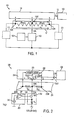
- a calibration current circuit block 102 provides current (e.g., in the form of pulses) to resistive structure 101 (Rx). Accordingly, calibration current generating circuit block 102 is used to measure the resistance of resistive structure 101 (Rx).
- the calibration current generating circuit 102 is coupled to at least the third node 130C in at least one state of operation. "Coupled" in this context means that the calibration current need not be injected exactly into the third node; rather, any appropriate location in the vicinity of the third node may also be used to inject the calibration current. However, the closer to the third node the better the accuracy.
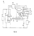
- FIG. 2 is a more detailed representation of a system 200 having a resistive structure 201, consistent with an embodiment of the present invention.
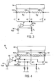
- the resistive structure 201 may be a piece of resistive material having at least a first connection node 230A, a second connection node 230B, and a third connection node 230C.
- Connection node 230C is between node 230A and node 230B.
- the desired response signal at node 230C is maximized, which decreases in amplitude the further node 230C is moved away from the center of the resistive structure 201.
- node 230C (from which the signal is taken) is positioned away from the center (e.g., at a distance where the resistance is 1/3 of the total resistance). It should be noted that when node 230C is too close to one of the nodes 230A or 230B, then the response signal may degrade.
- accuracy of the calibration for a given calibration current level is best when the signal Vavg has the largest amplitude, which occurs when interpolation parameter "a" is zero or close to zero.
- High accuracy can be accomplished by reducing the mechanical, thermal and electrical tolerances of the resistive structure to a reasonable level and by bringing the third node 230C as close to the electrical center equipotential line between the first and second nodes as reasonably possible (e.g., by proper exploitation of the given capabilities of the manufacturing process used to make the resistive structure).
- reference voltage source V REF 242 is set to a positive voltage (e.g., to 1.23V, which may be provided by a band-gap reference, but also can be from a reference that is much less precise than a band-gap reference).
- an idle phase is included.
- reference voltage source V REF 242 is again set to zero volts.
- all the functional blocks discussed above may be set to a power down state.
- the optional idle phase also helps to cool down the electronic components that generated the calibration current pulse.
- the idle phase is optional since the same cool down effect can be achieved in one embodiment by making the first phase of operation significantly longer than the second phase of operation.
- the absolute value of the difference between the signal samples taken in the first phase and the second phase is proportional to the product of the total resistance Rx * I CAL , even in the presence of offset voltages in the amplifiers or in the ADC.
- the proportionality factor itself may depend on the total system 200 gain.
Applications Claiming Priority (1)
| Application Number | Priority Date | Filing Date | Title |
|---|---|---|---|
| US13/734,581 US8947101B2 (en) | 2013-01-04 | 2013-01-04 | Method and system for measuring the resistance of a resistive structure |
Publications (2)
| Publication Number | Publication Date |
|---|---|
| EP2752672A1 true EP2752672A1 (de) | 2014-07-09 |
| EP2752672B1 EP2752672B1 (de) | 2019-11-13 |
Family
ID=49949479
Family Applications (1)
| Application Number | Title | Priority Date | Filing Date |
|---|---|---|---|
| EP14000004.3A Active EP2752672B1 (de) | 2013-01-04 | 2014-01-02 | Verfahren und System zum Messen des Widerstandes einer resistiven Struktur |
Country Status (4)
| Country | Link |
|---|---|
| US (1) | US8947101B2 (de) |
| EP (1) | EP2752672B1 (de) |
| CN (1) | CN103913639B (de) |
| TW (1) | TWI503646B (de) |
Cited By (3)
| Publication number | Priority date | Publication date | Assignee | Title |
|---|---|---|---|---|
| EP3159704A1 (de) * | 2015-10-23 | 2017-04-26 | ALSTOM Transport Technologies | Messkette für eine elektronische signalschaltung |
| CN108427017A (zh) * | 2018-01-31 | 2018-08-21 | 上海思愚智能科技有限公司 | 一种测试系统及终端 |
| WO2018158330A1 (de) * | 2017-03-03 | 2018-09-07 | Continental Automotive Gmbh | Stromsensor mit optimierter stromdichteverteilung, verfahren zum bestimmen eines laststroms |
Families Citing this family (19)
| Publication number | Priority date | Publication date | Assignee | Title |
|---|---|---|---|---|
| JP5930252B2 (ja) * | 2013-04-02 | 2016-06-08 | 株式会社村田製作所 | 擬似抵抗回路及び電荷検出回路 |
| EP3015877B1 (de) * | 2014-10-31 | 2016-10-26 | Samsung SDI Co., Ltd. | Verfahren zum Kalibrieren einer Strommesseinrichtung |
| DE102015216712A1 (de) * | 2015-09-01 | 2017-03-02 | Continental Automotive Gmbh | Vorrichtung zum Erfassen eines Widerstandswertes eines Messwiderstandes eines Messsensors |
| DE102016202501B4 (de) * | 2016-02-18 | 2022-03-17 | Continental Automotive Gmbh | Verfahren zum Bestimmen eines Kalibrierstrompulses |
| DE102016206958A1 (de) * | 2016-04-25 | 2017-10-26 | Continental Automotive Gmbh | Verfahren zum Bestimmen eines Laststroms und Batteriesensor |
| US10709616B2 (en) * | 2016-05-10 | 2020-07-14 | Xtrava Inc. | Contactless magnetic probe sensing and impedance imaging of liquid and solid excrement in diapers and other underclothing |
| CN106199426B (zh) * | 2016-07-01 | 2019-06-21 | 贵阳华旭科技开发有限公司 | 直流电机纹波模拟负载 |
| EP3546956B1 (de) * | 2018-03-29 | 2020-10-14 | AMS Sensors UK Limited | Schaltung zur messung eines widerstands |
| CN109270429B (zh) * | 2018-08-31 | 2021-02-05 | 中国船舶重工集团公司第七0九研究所 | 一种多通道高低温接口电路板噪声测量方法 |
| CN109596871A (zh) * | 2018-11-12 | 2019-04-09 | 中国计量科学研究院 | 量子电阻标准器 |
| CN109752597B (zh) * | 2019-01-11 | 2021-07-02 | 北京东方计量测试研究所 | 一种电感引线补偿装置及方法 |
| US11391805B2 (en) | 2019-05-10 | 2022-07-19 | Hamilton Sundstrand Corporation | Systems and methods for current sense resistor built-in-test |
| WO2021262457A2 (en) | 2020-06-12 | 2021-12-30 | Analog Devices International Unlimited Company | Self-calibrating polymer nano composite (pnc) sensing element |
| KR102478075B1 (ko) * | 2021-03-04 | 2022-12-15 | 현대모비스 주식회사 | 기생 인덕턴스 기반 스위칭전류 측정에서의 온도 영향 저감 장치 및 방법 |
| JP2023027568A (ja) | 2021-08-17 | 2023-03-02 | 株式会社デンソー | 電流センサ |
| JP2023027567A (ja) | 2021-08-17 | 2023-03-02 | 株式会社デンソー | 電流センサ |
| JP2023027569A (ja) * | 2021-08-17 | 2023-03-02 | 株式会社デンソー | 電流センサ |
| CN115290945B (zh) * | 2022-09-29 | 2022-12-23 | 山东阅芯电子科技有限公司 | 功率循环测试用高精度测试电流源及方法 |
| CN115840181A (zh) * | 2023-02-16 | 2023-03-24 | 南方电网产业投资集团有限责任公司 | 充电桩高压采样校准电路、方法及电子设备 |
Citations (11)
| Publication number | Priority date | Publication date | Assignee | Title |
|---|---|---|---|---|
| JPS60192270A (ja) * | 1984-03-13 | 1985-09-30 | Fuji Electric Co Ltd | 多点抵抗測定装置 |
| US4591743A (en) | 1983-12-19 | 1986-05-27 | National Semiconductor Corporation | Temperature compensated current sensing circuit |
| JPS62168067A (ja) * | 1986-01-21 | 1987-07-24 | Yamatake Honeywell Co Ltd | 抵抗値測定方法 |
| US5804979A (en) * | 1997-05-13 | 1998-09-08 | Fluke Corporation | Circuit for measuring in-circuit resistance and current |
| US6469481B1 (en) | 1998-12-25 | 2002-10-22 | Kabushiki Kaisha Toyoda Jidoshokki Seisakusho | Parallel RC current detection circuit and DC/DC converter with a parallel RC current detection circuit |
| DE10133525A1 (de) * | 2001-07-11 | 2003-01-30 | Bosch Gmbh Robert | Sensor mit Selbst-Test-Funktion |
| EP1607753A1 (de) * | 2004-06-17 | 2005-12-21 | Micrel Incorporated | Stromsensorschaltung mit Kelvinanschluss |
| WO2006002446A1 (de) * | 2004-07-06 | 2006-01-12 | Lem Norma Gmbh | Verfahren und einrichtung zur unterbrechungsfreien strommessung |
| US7358710B2 (en) | 2006-04-18 | 2008-04-15 | Dell Products L.P. | Temperature-compensated inductor DCR dynamic current sensing |
| US7536577B2 (en) | 2005-01-11 | 2009-05-19 | International Business Machines Corporation | Calibration technique for power measurement and management over multiple time frames |
| DE102011078334A1 (de) * | 2011-06-29 | 2013-01-03 | Robert Bosch Gmbh | Verfahren und System zum Kalibrieren eines Shunt-Widerstands |
Family Cites Families (14)
| Publication number | Priority date | Publication date | Assignee | Title |
|---|---|---|---|---|
| US5121064A (en) * | 1990-08-31 | 1992-06-09 | Allied-Signal, Inc. | Method and apparatus for calibrating resistance bridge-type transducers |
| US6618684B1 (en) * | 2000-01-26 | 2003-09-09 | Elster Electricity, Llc | System and method for digitally compensating frequency and temperature induced errors in amplitude and phase shift in current sensing of electronic energy meters |
| EP1450167A1 (de) * | 2003-02-24 | 2004-08-25 | ELMOS Semiconductor AG | Verfahren und Vorrichtung zum Messen des Widerstandswertes eines elektronischen Bauelements |
| US7042242B2 (en) * | 2004-05-25 | 2006-05-09 | Lsi Logic Corporation | Built-in self test technique for programmable impedance drivers for RapidChip and ASIC drivers |
| US7733163B1 (en) * | 2006-11-02 | 2010-06-08 | Marvell International Ltd. | Bias current compensation device and method |
| CN101021558B (zh) * | 2007-03-23 | 2011-05-11 | 中国科学院光电技术研究所 | 采用三环法测量导电环接触电阻的方法 |
| KR100867536B1 (ko) * | 2007-09-03 | 2008-11-06 | 삼성전기주식회사 | 리미터의 자가 이득 보정이 가능한 수신 신호 강도 검출기 |
| US8106669B2 (en) * | 2007-09-27 | 2012-01-31 | Guildline Instruments Limited | High current precision resistance measurement system |
| US8779777B2 (en) * | 2010-06-04 | 2014-07-15 | Linear Technology Corporation | Dynamic compensation of aging drift in current sense resistor |
| TWI491889B (zh) * | 2011-02-28 | 2015-07-11 | Hon Hai Prec Ind Co Ltd | 電阻測量電路及具有該電阻測量電路的電子裝置 |
| CN102262184B (zh) * | 2011-04-19 | 2013-02-27 | 哈尔滨工业大学 | 蓄电池内阻在线检测仪及内阻检测方法 |
| FR2975497B1 (fr) * | 2011-05-16 | 2013-06-28 | Centre Nat Rech Scient | Convertisseur electronique de puissance |
| CN102818934A (zh) * | 2011-06-08 | 2012-12-12 | 鸿富锦精密工业(深圳)有限公司 | 电感直流电阻测量电路 |
| US8604777B2 (en) * | 2011-07-13 | 2013-12-10 | Allegro Microsystems, Llc | Current sensor with calibration for a current divider configuration |
-
2013
- 2013-01-04 US US13/734,581 patent/US8947101B2/en active Active
-
2014
- 2014-01-02 EP EP14000004.3A patent/EP2752672B1/de active Active
- 2014-01-03 TW TW103100261A patent/TWI503646B/zh active
- 2014-01-06 CN CN201410005414.3A patent/CN103913639B/zh active Active
Patent Citations (11)
| Publication number | Priority date | Publication date | Assignee | Title |
|---|---|---|---|---|
| US4591743A (en) | 1983-12-19 | 1986-05-27 | National Semiconductor Corporation | Temperature compensated current sensing circuit |
| JPS60192270A (ja) * | 1984-03-13 | 1985-09-30 | Fuji Electric Co Ltd | 多点抵抗測定装置 |
| JPS62168067A (ja) * | 1986-01-21 | 1987-07-24 | Yamatake Honeywell Co Ltd | 抵抗値測定方法 |
| US5804979A (en) * | 1997-05-13 | 1998-09-08 | Fluke Corporation | Circuit for measuring in-circuit resistance and current |
| US6469481B1 (en) | 1998-12-25 | 2002-10-22 | Kabushiki Kaisha Toyoda Jidoshokki Seisakusho | Parallel RC current detection circuit and DC/DC converter with a parallel RC current detection circuit |
| DE10133525A1 (de) * | 2001-07-11 | 2003-01-30 | Bosch Gmbh Robert | Sensor mit Selbst-Test-Funktion |
| EP1607753A1 (de) * | 2004-06-17 | 2005-12-21 | Micrel Incorporated | Stromsensorschaltung mit Kelvinanschluss |
| WO2006002446A1 (de) * | 2004-07-06 | 2006-01-12 | Lem Norma Gmbh | Verfahren und einrichtung zur unterbrechungsfreien strommessung |
| US7536577B2 (en) | 2005-01-11 | 2009-05-19 | International Business Machines Corporation | Calibration technique for power measurement and management over multiple time frames |
| US7358710B2 (en) | 2006-04-18 | 2008-04-15 | Dell Products L.P. | Temperature-compensated inductor DCR dynamic current sensing |
| DE102011078334A1 (de) * | 2011-06-29 | 2013-01-03 | Robert Bosch Gmbh | Verfahren und System zum Kalibrieren eines Shunt-Widerstands |
Non-Patent Citations (2)
| Title |
|---|
| G. EIREA; S.R. SANDERS: "High Precision Load Current Sensing Using On-Line Calibration of Trace Resistance", IEEE TRANSACTIONS ON POWER ELECTRONICS, vol. 23, no. 2, March 2008 (2008-03-01), pages 907 - 914, XP011205436 |
| U. TIETZE, CH. SCHENK: "Halbleiter-Schaltungstechnik", vol. 10, 1993, SPRINGER VERLAG, Berlin, ISBN: 3-540-56184-6, pages: 371 - 373, XP002723495 * |
Cited By (6)
| Publication number | Priority date | Publication date | Assignee | Title |
|---|---|---|---|---|
| EP3159704A1 (de) * | 2015-10-23 | 2017-04-26 | ALSTOM Transport Technologies | Messkette für eine elektronische signalschaltung |
| FR3042878A1 (fr) * | 2015-10-23 | 2017-04-28 | Alstom Transp Tech | Chaine de mesure pour un circuit electronique de signalisation |
| WO2018158330A1 (de) * | 2017-03-03 | 2018-09-07 | Continental Automotive Gmbh | Stromsensor mit optimierter stromdichteverteilung, verfahren zum bestimmen eines laststroms |
| US11156643B2 (en) | 2017-03-03 | 2021-10-26 | Continental Automotive Gmbh | Current sensor with optimized current density distribution, method for determining a load current |
| CN108427017A (zh) * | 2018-01-31 | 2018-08-21 | 上海思愚智能科技有限公司 | 一种测试系统及终端 |
| CN108427017B (zh) * | 2018-01-31 | 2020-07-28 | 浙江万物工场智能科技有限公司 | 一种测试系统及终端 |
Also Published As
| Publication number | Publication date |
|---|---|
| TWI503646B (zh) | 2015-10-11 |
| TW201432409A (zh) | 2014-08-16 |
| US20140191768A1 (en) | 2014-07-10 |
| CN103913639A (zh) | 2014-07-09 |
| CN103913639B (zh) | 2018-05-18 |
| EP2752672B1 (de) | 2019-11-13 |
| US8947101B2 (en) | 2015-02-03 |
Similar Documents
| Publication | Publication Date | Title |
|---|---|---|
| EP2752672B1 (de) | Verfahren und System zum Messen des Widerstandes einer resistiven Struktur | |
| US8085024B2 (en) | Self-tuning digital current estimator for low-power switching converters | |
| US9588144B2 (en) | Current sensor | |
| Xue et al. | A compact planar Rogowski coil current sensor for active current balancing of parallel-connected silicon carbide MOSFETs | |
| JP7004585B2 (ja) | 半導体装置、負荷駆動システムおよびインダクタ電流の電流検出方法 | |
| EP3471255A1 (de) | Abtastende netzwerk-fehlanpassungskompensation für schaltspannungsregler mit eingangsspannungs- und strommessung | |
| TWI404316B (zh) | 具有改良的電流感測之直流至直流轉換器及相關之方法 | |
| US8264216B2 (en) | High-accuracy low-power current sensor with large dynamic range | |
| US5128611A (en) | Electronic electricity meter | |
| US8344722B2 (en) | Electric current measurement | |
| JPH0460555B2 (de) | ||
| CN108474811B (zh) | 用于感测电流的方法和装置 | |
| EP2400309B1 (de) | Stromsensor | |
| Ponjavic et al. | Nonlinear modeling of the self-oscillating fluxgate current sensor | |
| EP3152634B1 (de) | Spannungsregler mit geringer abfallspannung | |
| US9645193B2 (en) | Impedance source ranging apparatus and method | |
| Forghani-zadeh et al. | A lossless, accurate, self-calibrating current-sensing technique for DC-DC converters | |
| US10650946B1 (en) | Trimming method of DCR sensing circuits | |
| Garcea et al. | Digital auto-tuning system for inductor current sensing in VRM applications | |
| US9372212B2 (en) | Circuits and methods for measuring a current | |
| CN210377196U (zh) | 一种用模拟电路来提高电流采用精度的电路结构 | |
| JP2003035730A (ja) | 電流検出器 | |
| US10014810B1 (en) | Reduced-impedance active current measurement | |
| JP2013088146A (ja) | 試験装置 | |
| Ziegler et al. | Lossless inductor current sensing method with improved frequency response |
Legal Events
| Date | Code | Title | Description |
|---|---|---|---|
| 17P | Request for examination filed |
Effective date: 20140102 |
|
| AK | Designated contracting states |
Kind code of ref document: A1 Designated state(s): AL AT BE BG CH CY CZ DE DK EE ES FI FR GB GR HR HU IE IS IT LI LT LU LV MC MK MT NL NO PL PT RO RS SE SI SK SM TR |
|
| AX | Request for extension of the european patent |
Extension state: BA ME |
|
| PUAI | Public reference made under article 153(3) epc to a published international application that has entered the european phase |
Free format text: ORIGINAL CODE: 0009012 |
|
| R17P | Request for examination filed (corrected) |
Effective date: 20150108 |
|
| RBV | Designated contracting states (corrected) |
Designated state(s): AL AT BE BG CH CY CZ DE DK EE ES FI FR GB GR HR HU IE IS IT LI LT LU LV MC MK MT NL NO PL PT RO RS SE SI SK SM TR |
|
| 17Q | First examination report despatched |
Effective date: 20160919 |
|
| STAA | Information on the status of an ep patent application or granted ep patent |
Free format text: STATUS: EXAMINATION IS IN PROGRESS |
|
| GRAP | Despatch of communication of intention to grant a patent |
Free format text: ORIGINAL CODE: EPIDOSNIGR1 |
|
| STAA | Information on the status of an ep patent application or granted ep patent |
Free format text: STATUS: GRANT OF PATENT IS INTENDED |
|
| INTG | Intention to grant announced |
Effective date: 20190621 |
|
| GRAS | Grant fee paid |
Free format text: ORIGINAL CODE: EPIDOSNIGR3 |
|
| GRAA | (expected) grant |
Free format text: ORIGINAL CODE: 0009210 |
|
| STAA | Information on the status of an ep patent application or granted ep patent |
Free format text: STATUS: THE PATENT HAS BEEN GRANTED |
|
| AK | Designated contracting states |
Kind code of ref document: B1 Designated state(s): AL AT BE BG CH CY CZ DE DK EE ES FI FR GB GR HR HU IE IS IT LI LT LU LV MC MK MT NL NO PL PT RO RS SE SI SK SM TR |
|
| REG | Reference to a national code |
Ref country code: AT Ref legal event code: REF Ref document number: 1202239 Country of ref document: AT Kind code of ref document: T Effective date: 20191115 Ref country code: CH Ref legal event code: EP |
|
| REG | Reference to a national code |
Ref country code: DE Ref legal event code: R096 Ref document number: 602014056633 Country of ref document: DE |
|
| REG | Reference to a national code |
Ref country code: IE Ref legal event code: FG4D |
|
| REG | Reference to a national code |
Ref country code: NL Ref legal event code: MP Effective date: 20191113 |
|
| REG | Reference to a national code |
Ref country code: LT Ref legal event code: MG4D |
|
| PG25 | Lapsed in a contracting state [announced via postgrant information from national office to epo] |
Ref country code: NL Free format text: LAPSE BECAUSE OF FAILURE TO SUBMIT A TRANSLATION OF THE DESCRIPTION OR TO PAY THE FEE WITHIN THE PRESCRIBED TIME-LIMIT Effective date: 20191113 Ref country code: ES Free format text: LAPSE BECAUSE OF FAILURE TO SUBMIT A TRANSLATION OF THE DESCRIPTION OR TO PAY THE FEE WITHIN THE PRESCRIBED TIME-LIMIT Effective date: 20191113 Ref country code: GR Free format text: LAPSE BECAUSE OF FAILURE TO SUBMIT A TRANSLATION OF THE DESCRIPTION OR TO PAY THE FEE WITHIN THE PRESCRIBED TIME-LIMIT Effective date: 20200214 Ref country code: NO Free format text: LAPSE BECAUSE OF FAILURE TO SUBMIT A TRANSLATION OF THE DESCRIPTION OR TO PAY THE FEE WITHIN THE PRESCRIBED TIME-LIMIT Effective date: 20200213 Ref country code: LT Free format text: LAPSE BECAUSE OF FAILURE TO SUBMIT A TRANSLATION OF THE DESCRIPTION OR TO PAY THE FEE WITHIN THE PRESCRIBED TIME-LIMIT Effective date: 20191113 Ref country code: PL Free format text: LAPSE BECAUSE OF FAILURE TO SUBMIT A TRANSLATION OF THE DESCRIPTION OR TO PAY THE FEE WITHIN THE PRESCRIBED TIME-LIMIT Effective date: 20191113 Ref country code: SE Free format text: LAPSE BECAUSE OF FAILURE TO SUBMIT A TRANSLATION OF THE DESCRIPTION OR TO PAY THE FEE WITHIN THE PRESCRIBED TIME-LIMIT Effective date: 20191113 Ref country code: LV Free format text: LAPSE BECAUSE OF FAILURE TO SUBMIT A TRANSLATION OF THE DESCRIPTION OR TO PAY THE FEE WITHIN THE PRESCRIBED TIME-LIMIT Effective date: 20191113 Ref country code: FI Free format text: LAPSE BECAUSE OF FAILURE TO SUBMIT A TRANSLATION OF THE DESCRIPTION OR TO PAY THE FEE WITHIN THE PRESCRIBED TIME-LIMIT Effective date: 20191113 Ref country code: BG Free format text: LAPSE BECAUSE OF FAILURE TO SUBMIT A TRANSLATION OF THE DESCRIPTION OR TO PAY THE FEE WITHIN THE PRESCRIBED TIME-LIMIT Effective date: 20200213 Ref country code: PT Free format text: LAPSE BECAUSE OF FAILURE TO SUBMIT A TRANSLATION OF THE DESCRIPTION OR TO PAY THE FEE WITHIN THE PRESCRIBED TIME-LIMIT Effective date: 20200313 |
|
| PG25 | Lapsed in a contracting state [announced via postgrant information from national office to epo] |
Ref country code: RS Free format text: LAPSE BECAUSE OF FAILURE TO SUBMIT A TRANSLATION OF THE DESCRIPTION OR TO PAY THE FEE WITHIN THE PRESCRIBED TIME-LIMIT Effective date: 20191113 Ref country code: IS Free format text: LAPSE BECAUSE OF FAILURE TO SUBMIT A TRANSLATION OF THE DESCRIPTION OR TO PAY THE FEE WITHIN THE PRESCRIBED TIME-LIMIT Effective date: 20200313 Ref country code: HR Free format text: LAPSE BECAUSE OF FAILURE TO SUBMIT A TRANSLATION OF THE DESCRIPTION OR TO PAY THE FEE WITHIN THE PRESCRIBED TIME-LIMIT Effective date: 20191113 |
|
| PG25 | Lapsed in a contracting state [announced via postgrant information from national office to epo] |
Ref country code: AL Free format text: LAPSE BECAUSE OF FAILURE TO SUBMIT A TRANSLATION OF THE DESCRIPTION OR TO PAY THE FEE WITHIN THE PRESCRIBED TIME-LIMIT Effective date: 20191113 |
|
| PG25 | Lapsed in a contracting state [announced via postgrant information from national office to epo] |
Ref country code: CZ Free format text: LAPSE BECAUSE OF FAILURE TO SUBMIT A TRANSLATION OF THE DESCRIPTION OR TO PAY THE FEE WITHIN THE PRESCRIBED TIME-LIMIT Effective date: 20191113 Ref country code: RO Free format text: LAPSE BECAUSE OF FAILURE TO SUBMIT A TRANSLATION OF THE DESCRIPTION OR TO PAY THE FEE WITHIN THE PRESCRIBED TIME-LIMIT Effective date: 20191113 Ref country code: DK Free format text: LAPSE BECAUSE OF FAILURE TO SUBMIT A TRANSLATION OF THE DESCRIPTION OR TO PAY THE FEE WITHIN THE PRESCRIBED TIME-LIMIT Effective date: 20191113 Ref country code: EE Free format text: LAPSE BECAUSE OF FAILURE TO SUBMIT A TRANSLATION OF THE DESCRIPTION OR TO PAY THE FEE WITHIN THE PRESCRIBED TIME-LIMIT Effective date: 20191113 |
|
| REG | Reference to a national code |
Ref country code: DE Ref legal event code: R097 Ref document number: 602014056633 Country of ref document: DE |
|
| REG | Reference to a national code |
Ref country code: AT Ref legal event code: MK05 Ref document number: 1202239 Country of ref document: AT Kind code of ref document: T Effective date: 20191113 |
|
| PG25 | Lapsed in a contracting state [announced via postgrant information from national office to epo] |
Ref country code: SK Free format text: LAPSE BECAUSE OF FAILURE TO SUBMIT A TRANSLATION OF THE DESCRIPTION OR TO PAY THE FEE WITHIN THE PRESCRIBED TIME-LIMIT Effective date: 20191113 Ref country code: MC Free format text: LAPSE BECAUSE OF FAILURE TO SUBMIT A TRANSLATION OF THE DESCRIPTION OR TO PAY THE FEE WITHIN THE PRESCRIBED TIME-LIMIT Effective date: 20191113 Ref country code: SM Free format text: LAPSE BECAUSE OF FAILURE TO SUBMIT A TRANSLATION OF THE DESCRIPTION OR TO PAY THE FEE WITHIN THE PRESCRIBED TIME-LIMIT Effective date: 20191113 |
|
| REG | Reference to a national code |
Ref country code: CH Ref legal event code: PL |
|
| PLBE | No opposition filed within time limit |
Free format text: ORIGINAL CODE: 0009261 |
|
| STAA | Information on the status of an ep patent application or granted ep patent |
Free format text: STATUS: NO OPPOSITION FILED WITHIN TIME LIMIT |
|
| REG | Reference to a national code |
Ref country code: BE Ref legal event code: MM Effective date: 20200131 |
|
| 26N | No opposition filed |
Effective date: 20200814 |
|
| PG25 | Lapsed in a contracting state [announced via postgrant information from national office to epo] |
Ref country code: LU Free format text: LAPSE BECAUSE OF NON-PAYMENT OF DUE FEES Effective date: 20200102 |
|
| PG25 | Lapsed in a contracting state [announced via postgrant information from national office to epo] |
Ref country code: CH Free format text: LAPSE BECAUSE OF NON-PAYMENT OF DUE FEES Effective date: 20200131 Ref country code: SI Free format text: LAPSE BECAUSE OF FAILURE TO SUBMIT A TRANSLATION OF THE DESCRIPTION OR TO PAY THE FEE WITHIN THE PRESCRIBED TIME-LIMIT Effective date: 20191113 Ref country code: AT Free format text: LAPSE BECAUSE OF FAILURE TO SUBMIT A TRANSLATION OF THE DESCRIPTION OR TO PAY THE FEE WITHIN THE PRESCRIBED TIME-LIMIT Effective date: 20191113 Ref country code: BE Free format text: LAPSE BECAUSE OF NON-PAYMENT OF DUE FEES Effective date: 20200131 Ref country code: LI Free format text: LAPSE BECAUSE OF NON-PAYMENT OF DUE FEES Effective date: 20200131 |
|
| PG25 | Lapsed in a contracting state [announced via postgrant information from national office to epo] |
Ref country code: IT Free format text: LAPSE BECAUSE OF FAILURE TO SUBMIT A TRANSLATION OF THE DESCRIPTION OR TO PAY THE FEE WITHIN THE PRESCRIBED TIME-LIMIT Effective date: 20191113 Ref country code: IE Free format text: LAPSE BECAUSE OF NON-PAYMENT OF DUE FEES Effective date: 20200102 |
|
| REG | Reference to a national code |
Ref country code: DE Ref legal event code: R082 Ref document number: 602014056633 Country of ref document: DE Representative=s name: WITHERS & ROGERS LLP, DE Ref country code: DE Ref legal event code: R082 Ref document number: 602014056633 Country of ref document: DE Representative=s name: MUELLER-BORE & PARTNER PATENTANWAELTE PARTG MB, DE Ref country code: DE Ref legal event code: R081 Ref document number: 602014056633 Country of ref document: DE Owner name: ANALOG DEVICES INTERNATIONAL UNLIMITED COMPANY, IE Free format text: FORMER OWNER: LINEAR TECHNOLOGY CORPORATION, MILPITAS, CALIF., US |
|
| REG | Reference to a national code |
Ref country code: DE Ref legal event code: R082 Ref document number: 602014056633 Country of ref document: DE Representative=s name: WITHERS & ROGERS LLP, DE |
|
| REG | Reference to a national code |
Ref country code: GB Ref legal event code: 732E Free format text: REGISTERED BETWEEN 20211125 AND 20211201 |
|
| PG25 | Lapsed in a contracting state [announced via postgrant information from national office to epo] |
Ref country code: TR Free format text: LAPSE BECAUSE OF FAILURE TO SUBMIT A TRANSLATION OF THE DESCRIPTION OR TO PAY THE FEE WITHIN THE PRESCRIBED TIME-LIMIT Effective date: 20191113 Ref country code: MT Free format text: LAPSE BECAUSE OF FAILURE TO SUBMIT A TRANSLATION OF THE DESCRIPTION OR TO PAY THE FEE WITHIN THE PRESCRIBED TIME-LIMIT Effective date: 20191113 Ref country code: CY Free format text: LAPSE BECAUSE OF FAILURE TO SUBMIT A TRANSLATION OF THE DESCRIPTION OR TO PAY THE FEE WITHIN THE PRESCRIBED TIME-LIMIT Effective date: 20191113 |
|
| PG25 | Lapsed in a contracting state [announced via postgrant information from national office to epo] |
Ref country code: MK Free format text: LAPSE BECAUSE OF FAILURE TO SUBMIT A TRANSLATION OF THE DESCRIPTION OR TO PAY THE FEE WITHIN THE PRESCRIBED TIME-LIMIT Effective date: 20191113 |
|
| PGFP | Annual fee paid to national office [announced via postgrant information from national office to epo] |
Ref country code: DE Payment date: 20221220 Year of fee payment: 10 |
|
| PGFP | Annual fee paid to national office [announced via postgrant information from national office to epo] |
Ref country code: GB Payment date: 20231219 Year of fee payment: 11 |
|
| PGFP | Annual fee paid to national office [announced via postgrant information from national office to epo] |
Ref country code: FR Payment date: 20231219 Year of fee payment: 11 |