EP3159239B1 - Faltbarer rahmen für kinderwägen - Google Patents
Faltbarer rahmen für kinderwägen Download PDFInfo
- Publication number
- EP3159239B1 EP3159239B1 EP16194539.9A EP16194539A EP3159239B1 EP 3159239 B1 EP3159239 B1 EP 3159239B1 EP 16194539 A EP16194539 A EP 16194539A EP 3159239 B1 EP3159239 B1 EP 3159239B1
- Authority
- EP
- European Patent Office
- Prior art keywords
- pair
- legs
- carriage
- hinge axis
- front legs
- Prior art date
- Legal status (The legal status is an assumption and is not a legal conclusion. Google has not performed a legal analysis and makes no representation as to the accuracy of the status listed.)
- Not-in-force
Links
- 210000001364 upper extremity Anatomy 0.000 claims description 85
- 230000008878 coupling Effects 0.000 claims description 22
- 238000010168 coupling process Methods 0.000 claims description 22
- 238000005859 coupling reaction Methods 0.000 claims description 22
- 230000000284 resting effect Effects 0.000 claims description 10
- 230000000295 complement effect Effects 0.000 claims description 2
- 238000006073 displacement reaction Methods 0.000 claims 1
- 239000000463 material Substances 0.000 description 2
- 230000005540 biological transmission Effects 0.000 description 1
- 230000001419 dependent effect Effects 0.000 description 1
- 239000004744 fabric Substances 0.000 description 1
- NJPPVKZQTLUDBO-UHFFFAOYSA-N novaluron Chemical compound C1=C(Cl)C(OC(F)(F)C(OC(F)(F)F)F)=CC=C1NC(=O)NC(=O)C1=C(F)C=CC=C1F NJPPVKZQTLUDBO-UHFFFAOYSA-N 0.000 description 1
- GOLXNESZZPUPJE-UHFFFAOYSA-N spiromesifen Chemical compound CC1=CC(C)=CC(C)=C1C(C(O1)=O)=C(OC(=O)CC(C)(C)C)C11CCCC1 GOLXNESZZPUPJE-UHFFFAOYSA-N 0.000 description 1
- 230000003019 stabilising effect Effects 0.000 description 1
Images


Classifications
-
- B—PERFORMING OPERATIONS; TRANSPORTING
- B62—LAND VEHICLES FOR TRAVELLING OTHERWISE THAN ON RAILS
- B62B—HAND-PROPELLED VEHICLES, e.g. HAND CARTS OR PERAMBULATORS; SLEDGES
- B62B9/00—Accessories or details specially adapted for children's carriages or perambulators
- B62B9/26—Securing devices for bags or toys ; Arrangements of racks, bins, trays or other devices for transporting articles
-
- B—PERFORMING OPERATIONS; TRANSPORTING
- B62—LAND VEHICLES FOR TRAVELLING OTHERWISE THAN ON RAILS
- B62B—HAND-PROPELLED VEHICLES, e.g. HAND CARTS OR PERAMBULATORS; SLEDGES
- B62B7/00—Carriages for children; Perambulators, e.g. dolls' perambulators
- B62B7/04—Carriages for children; Perambulators, e.g. dolls' perambulators having more than one wheel axis; Steering devices therefor
- B62B7/06—Carriages for children; Perambulators, e.g. dolls' perambulators having more than one wheel axis; Steering devices therefor collapsible or foldable
- B62B7/062—Coupling unit between front wheels, rear wheels and handle
-
- B—PERFORMING OPERATIONS; TRANSPORTING
- B62—LAND VEHICLES FOR TRAVELLING OTHERWISE THAN ON RAILS
- B62B—HAND-PROPELLED VEHICLES, e.g. HAND CARTS OR PERAMBULATORS; SLEDGES
- B62B7/00—Carriages for children; Perambulators, e.g. dolls' perambulators
- B62B7/04—Carriages for children; Perambulators, e.g. dolls' perambulators having more than one wheel axis; Steering devices therefor
- B62B7/06—Carriages for children; Perambulators, e.g. dolls' perambulators having more than one wheel axis; Steering devices therefor collapsible or foldable
- B62B7/064—Carriages for children; Perambulators, e.g. dolls' perambulators having more than one wheel axis; Steering devices therefor collapsible or foldable the handle bar being parallel to the front leg
- B62B7/066—Carriages for children; Perambulators, e.g. dolls' perambulators having more than one wheel axis; Steering devices therefor collapsible or foldable the handle bar being parallel to the front leg the handle bar moves in parallel relation during folding
-
- B—PERFORMING OPERATIONS; TRANSPORTING
- B62—LAND VEHICLES FOR TRAVELLING OTHERWISE THAN ON RAILS
- B62B—HAND-PROPELLED VEHICLES, e.g. HAND CARTS OR PERAMBULATORS; SLEDGES
- B62B7/00—Carriages for children; Perambulators, e.g. dolls' perambulators
- B62B7/04—Carriages for children; Perambulators, e.g. dolls' perambulators having more than one wheel axis; Steering devices therefor
- B62B7/14—Carriages for children; Perambulators, e.g. dolls' perambulators having more than one wheel axis; Steering devices therefor with detachable or rotatably-mounted body
- B62B7/145—Carriages for children; Perambulators, e.g. dolls' perambulators having more than one wheel axis; Steering devices therefor with detachable or rotatably-mounted body the body being a rigid seat, e.g. a shell
-
- B—PERFORMING OPERATIONS; TRANSPORTING
- B62—LAND VEHICLES FOR TRAVELLING OTHERWISE THAN ON RAILS
- B62B—HAND-PROPELLED VEHICLES, e.g. HAND CARTS OR PERAMBULATORS; SLEDGES
- B62B2205/00—Hand-propelled vehicles or sledges being foldable or dismountable when not in use
- B62B2205/26—Arrangements for standing up in folded position
Definitions
- This invention relates to a convertible carriage that is book-like foldable and usable as a push frame for baby strollers.
- Baby strollers wherein the push frame is of the "book-like" foldable type by rotation of the front legs and the rear legs relative to one another about a same or different axes parallel to the ground and orthogonal to the longitudinal development of the frame, the handle folding onto the front and rear legs by sliding or by rotation.
- Each of the two front legs of these known frames is connected to the respective rear leg by means of one or more transmission bars, which favour the relative movement, without, however, stiffening or stabilising the structure in a substantial manner.
- baskets are not suitable for carrying bulky or heavy objects such as, for example, shopping packets.
- the aim of the present invention is to overcome the drawbacks of the prior art.
- a particular aim is to provide a convertible carriage that is book-like foldable and usable as a push frame for baby strollers, the structure of which is particularly stable in particular in the open position.
- Another aim of this invention is to make a convertible carriage that is book-like foldable and usable as a push frame for baby strollers, which is provided with a spacious and resistant basket and which has limited dimensions.
- Another aim of this invention is to make a convertible carriage that is book-like foldable and usable as a push frame for baby strollers, which is very practical to use and easy to manoeuvre and, when used as a push frame for baby strollers, guarantees a high degree of safety for the child in any condition.
- a further aim of this invention is to make a convertible carriage that is book-like foldable and usable as a push frame for baby strollers, which is particularly simple and functional and cost effective.
- the numeral 10 indicates a convertible carriage that is book-like foldable and usable as a push frame for baby strollers.
- Adjectives such as upper, lower, front or rear are to be intended as referring to a carriage 10 with respect to this system of Cartesian axes and in its usual configuration of use.
- the carriage 10 is of the convertible type, in the sense that it may adopt different use configurations both as a carriage in itself and as a push frame for baby strollers.
- the carriage 10 is of the foldable type; in particular it is of the book-like foldable type and takes up an open configuration for use and a closed configuration when not in use.
- the carriage 10 comprises:
- the front legs 11 are coupled with one another close to their lower end 11a, that is, the end to which a respective front wheel 12 is coupled, by means of a crosspiece 17.
- Each of the two front legs 11 preferably has the shape substantially of an upturned "L", the two sections of which form together an angle greater than 90° and of which the section of greater length forms the actual front leg and the section of shorter length extends towards the rear legs 13 and, when the carriage 10 is in its open configuration, is parallel to the ground on which the carriage rests.
- the rear legs 13 are coupled with one another close to their lower end 13a, that is, the end to which a respective rear wheel 14 is coupled, by means of a crosspiece 18.
- Each of the two front legs 11 and the two rear legs 13 can be made as a unique body or be formed by several members assembled together to form a unique body.
- the rear legs 13 and the front legs 11 are articulated in a rotatable manner about a common first hinge axis or about two different first hinge axes defined in an articulation joint (not shown) and parallel to the ground and orthogonal to the movement direction of the carriage 10, so as to be able to rotate one relative to the other between an open configuration, wherein they are spaced from one other, and a closed configuration, wherein they are side by side.
- the rear legs 13 and the front legs 11 are articulated together in a rotatable manner about a common first hinge axis A parallel to the ground on which the carriage 10 rests and orthogonal to the movement direction B of the carriage 10, where the expression "movement direction B" means the direction parallel to the longitudinal axis of development of the carriage 10 as indicated in the enclosed drawings.
- the pair of rear legs 13 and the pair of front legs 11 rotate relative to one another about the first hinge axis A as unique bodies.
- the first hinge axis A is defined at the upper ends 11b and 13b of the front legs 11 and of the rear legs 13.
- the first hinge axis A is defined at the upper end 13b of the rear legs and at the upper end 11b of the front legs 11 that is defined by the end of the shortest section of their L-shape.
- the operating shafts 15 can, advantageously, be of the telescopic type.
- the operating shafts 15 each have a lower end 15a and an upper end 15b; they are connected together at their upper end 15b by a crosspiece 19, at which the handle 16 is defined.
- the operating shafts 15 can be coupled to the front legs 11 and to the rear legs 13 in a rotatable manner about a hinge axis parallel or coincident with the first hinge axis A so as to fold either on the front legs 11 or on the rear legs 13, with a forward and backward rotation, respectively, for the carriage 10 to pass from an open configuration to a closed configuration, the inverse passage taking place with a rotation of the operating shafts 15 in the opposite direction.
- the operating shafts 15 are coupled to the front legs 11 in a movable manner with a sliding movement component in a direction parallel to the longitudinal development direction of the front legs 11, so as to pass from a position of use, wherein they extend upwards and rearwards with respect to front legs 11, to a rest position, wherein they are retracted towards the front legs 11 and placed side by side with the latter, and vice versa.
- the operating shafts 15 are parallel to the front legs 11 and are coupled to the front legs 11 in an axially slidable manner along a direction parallel to the longitudinal development of the front legs 11.
- the operating shafts 15 are coupled to the shortest section of the "L" shape of the front legs 11.
- the two operating shafts 15 comprise an end section which terminates at their lower end 15a and which, when they are in their position of use, is positioned side by side the respective front leg 11 and, with reference to the embodiment shown in the enclosed drawings, rearly with respect to the front leg 11 and below the shortest section of the "L" shape of the front legs 11.
- locking means of the removable type are provided for locking the operating shafts 15 in their position of use; these locking means, which, for example, can be of the locking bolt type, are advantageously controlled by pushbuttons or levers 20 located at the handle 16.
- the carriage 10 comprises a pair of plate-like bodies, respectively a first plate-like body 22 and a second plate-like body 23, which are interposed between the pair of front legs 11 and the pair of rear legs 13 to form a compass.
- the first plate-like body 22 and the second plate-like body 23 are articulated to one another, at one end thereof, about a second hinge axis E and they are articulated, at their opposite ends, respectively to the pair of front legs 11 and to the pair of rear legs 13 respectively about a third hinge axis F and a fourth hinge axis G.
- the first plate-like body 22 has the front end articulated in a hinge-like manner to a portion of the front legs 11 close to lower end 11a thereof.
- the first plate-like body 22 has the front end articulated in a hinge-like manner to the crosspiece 17 that connects the two front legs 11; therefore, the crosspiece 17 defines the third hinge axis F.
- the second plate-like body 23 has the rear end articulated in a hinge-like manner to a portion of the rear legs 13 close to lower end 13a thereof.
- the second plate-like body 23 has the rear end articulated in a hinge-like manner to the crosspiece 18 that connects the two rear legs 13; therefore, the crosspiece 18 defines the fourth hinge axis G.
- the rear end of the first plate-like body 22 and the front end of the second plate-like body 23 are articulated to one another about a pin that defines the second hinge axis E.
- the first plate-like body 22 and the second plate-like body 23 act as a supporting plan for supporting thereon the bottom 29a of a basket 29 foldable in a bellows manner, said basket being interposed between the front legs 11 and the rear legs 13 and having the upper edge associated with the front legs 11 and the rear legs 13.
- the distance between the second hinge axis E and the third hinge axis F is different from, preferably greater than, the distance between the second hinge axis E and the fourth hinge axis G.
- the length of the first plate-like body 22 considered along the longitudinal development of the carriage 10 is greater than the length of the second plate-like body 23.
- the first plate-like body 22 and the second plate-like body 23 can advantageously have lightened portions and/or reinforced portions, for example, by ribs.
- the first plate-like body 22 and the second plate-like body 23 are substantially coplanar to one another and parallel to the ground.
- plate-like body means a body having a substantially planar extension and the width of which is, at least at one of its portions, almost equal to the distance between the front legs 11 or rear legs 13.
- the second hinge axis E, the third hinge axis F and the fourth hinge axis G are parallel to the ground and orthogonal to the movement direction B of the carriage 10; moreover, they are different from one another and also different from the first hinge axis A.
- the carriage 10 also comprises a pair of shaft-like bodies, respectively a first shaft-like body 24 and a second shaft-like body 25, which form a quadrilateral articulated with the pair formed by the first plate-like body 22 and the second plate-like body 23.
- the first shaft-like body 24 and the second shaft-like body 25 are interposed between the pair of front legs 11 and the pair of rear legs 13, are articulated to one another, at an end, about a fifth hinge axis H and are articulated, at the opposite end, respectively to the pair of front legs 11 (or to the first plate-like body 22 that is articulated to the front legs 11) and to the pair of rear legs 13 (or to the second plate-like body 23 that is articulated to the rear legs 13) respectively about a sixth hinge axis I and a seventh hinge axis L, which are coincident or parallel respectively with the third hinge axis F and the fourth hinge axis G.
- the first shaft-like body 24 and the second shaft-like body 25 are substantially coplanar to one another and they extend below the first plate-like body 22 and the second plate-like body 23.
- the first shaft-like body 24 has the front end articulated in a hinge-like manner to the pair of front legs 11 in a rotatable manner about the sixth hinge axis I that, advantageously, coincides with the third hinge axis F; the front end of the first plate-like body 22 and of the first shaft-like body 24 are therefore both articulated about the crosspiece 17.
- the second shaft-like body 25 has the rear end articulated in a hinge-like manner to the second plate-like body 23 about a pin that defines the seventh hinge axis L.
- the rear end of the first shaft-like body 24 and the front end of the second shaft-like body 25 are articulated to one another about a pin that defines the fifth hinge axis H.
- one of the two plate-like bodies or one of the two shaft-like bodies comprises at one of its ends an appendage that, when the carriage 10 is in the closed configuration, acts as a strut or pedestal for resting on the ground.
- the first shaft-like body 24 comprises such an appendage 26 that is defined at the end of the first shaft-like body 24 articulated to the second shaft-like body 25.
- the first shaft-like body 24 and the second shaft-like body 25 can have various shapes advantageously lightened and/or reinforced for instance by ribs.
- the pair of plate-like bodies and, if present, the pair of shaft-like bodies stiffen and stabilise the structure of the carriage 10 when it is in its open configuration and favour the relative movement of the front legs 11 and of the rear legs 13 in the passage of the carriage 10 from its open to its closed configurations and vice versa.
- the carriage 10 also comprises a pair of levers 21, respectively a right lever and a left lever, each of which has a front end 21a and a rear end 21b.
- the front end 21a of the two levers 21, right and left, is hinged to the respective operating shaft 15, right and left, about a common eighth hinge axis C.
- the rear end 21b of the two levers 21, right and left is hinged to the respective rear leg 13, right and left, about a common ninth hinge axis D.
- the eighth hinge axis C and the ninth hinge axis D are parallel to one another and different; moreover, they are parallel different from the first hinge axis A and from the remaining hinge axes mentioned above.
- the eighth hinge axis C is defined at the lower ends 15a of the operating shafts 15 and the ninth hinge axis D is defined at a substantially median point of the longitudinal development of the rear legs 13.
- the shafts 21 favour the relative movement of the front legs 11 and the rear legs 13 in the passage of the carriage 10 from its open to its closed configurations and vice versa.
- At least one of a front portion of the upper edge and a rear portion of the upper edge of the basket 29 is constrained to a respective supporting body that is articulated respectively to the pair of front legs 11 or to the pair of rear legs 13 in a movable manner between a raised position, wherein it projects respectively from the pair of front legs 11 or from the pair of rear legs 13, and a lowered position, wherein it is side by side and substantially coplanar respectively with the pair of front legs 11 or the pair of rear legs 13.
- the carriage 10 comprises a pair of such supporting bodies that are advantageously constituted by arch tubular bodies, respectively a front arch tubular body 27 and a rear arch tubular body 28 which have the respective ends articulated in a hinge-like manner respectively to the pair of front legs 11 and to the pair of rear legs 13 respectively about a tenth hinge axis M and an eleventh hinge axis N, said axes being parallel to and different from all of the hinge axes, starting from the first hinge axis A to the ninth hinge axis L, as defined above.
- arch tubular bodies respectively a front arch tubular body 27 and a rear arch tubular body 28 which have the respective ends articulated in a hinge-like manner respectively to the pair of front legs 11 and to the pair of rear legs 13 respectively about a tenth hinge axis M and an eleventh hinge axis N, said axes being parallel to and different from all of the hinge axes, starting from the first hinge axis A to the ninth hinge axis L, as defined above.
- the first arch tubular body 27 and the second arch tubular body 28 advantageously have the shape of a "U", a "C” or the like and each define a portion of the upper edge of a basket 29 foldable in a bellows manner, which is only schematically shown in the enclosed drawings by the dashed line.
- the first arch tubular body 27 is movable between a raised position, wherein it projects from and in front of the pair of front legs 11 to support a front end of the basket 29, and a lowered position, wherein it is side by side and substantially coplanar with the pair of front legs 11.
- the second arch tubular body 28 is movable between a raised position, wherein it projects from and rearwards the pair of rear legs 13 to support a rear end of the basket 29, and a lowered position, wherein it is side by side and substantially coplanar with the pair of rear legs 13.
- the expression "substantially coplanar" referred to the front tubular body 27 and to the rear tubular body 28 in their lowered position respectively on the front legs 11 and on the rear legs 13 means coplanar with the exception of shifts of a few degrees due to dimensions and articulations.
- the rotation of the first arch tubular body 27 about the respective tenth hinge axis M is advantageously independent of the rotation of the second arch body 28 about the respective eleventh hinge axis N, so that the front and rear ends of the basket 29 can be folded independently of one another.
- Locking means are also present for the removable locking of the first arch tubular body 27 and the second arch tubular body 28 in their raised and lowered positions, which are not described in detail being of a type immediately comprehensible to the skilled person and which, for example, can be of the interlocking or snap type or the like.
- the first plate-like body 22 and the second plate-like body 23 form an element for supporting the bottom 29a of the basket 29.
- the basket 29 comprises in particular a flexible cover that defines its walls and the bottom.
- This cover has an upper perimetral edge coupled, advantageously in a removable manner, to the first arch tubular body 27 and to the second arch tubular body 28.
- Said cover has bottom portions that are coupled, advantageously in a removable manner, to the pair of front legs 11 and to the pair of rear legs 13 and preferably to the respective crosspiece 17 and 18.
- the carriage 10 also comprises coupling members 30 for the removable coupling with a baby containment compartment 100 that is equipped with complementary coupling members.
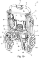
- the compartment 100 consists of a shuttle, a baby seat or, preferably, a car baby seat as shown in Figures 11 and 12 .
- the coupling members 30 can have various configurations and the carriage 10 that can comprise coupling members of different types.
- the coupling members 30 can, for example, comprise a transversal shaft or bar 31, which connects the front legs 11 or rear legs 13 and with which bracket or hooking elements can be coupled, said elements being provided on the compartment; it is noted that such a bar 31 is defined close to the first hinge axis A and, advantageously, coincident with it and also acts as a stiffening element for the carriage 10.
- the coupling members 30 can comprise male or female elements 32 defined at the front legs 11 or rear legs 13 and advantageously at the upper end 11b and 13b of them for the snap or interlocking coupling with corresponding male of female elements provided on the compartment.
- the coupling members 30 can comprise a support plate 33 that extends between the front legs 11 or rear legs 13 and that is equipped with coupling elements for the mutual coupling with matching coupling elements provided on the compartment.
- the plate 33 can be advantageously coupled to the carriage 10 in a removable manner by means of male elements 34 that are integral with it and insertable into female elements 32 and by means of a bracket 35 that can be coupled on the bar 31.
- Another object of the present invention is a baby stroller comprising a push frame to which a baby compartment 100 is coupled in a removable manner, wherein the push frame comprises a carriage 10 as shown in Figures 11 and 12 .
- the carriage 10 takes up an open configuration ( Figures 1 to 6 ), wherein the pair of front legs 11 and the pair of rear legs 13 are spaced apart from one another, the plate-like bodies 22 and 23 extend between them and are substantially coplanar to one another and the operating shafts 15 are in their position of use wherein they extend upwards and rearly with respect to the pair of front legs 11.
- the basket 29 can take up various configurations as shown in Figures 3 to 6 depending on the position taken up by the first arch tubular body 27 and by the second arch tubular body 28.
- both the arch tubular bodies 27 and 28 are locked in their raised position and the basket 29 is in its configuration of maximum containment capacity.
- the first arch tubular body 27 is locked in its lowered position thereby making the inside of the basket 29 accessible from the front as well as, as usual, from above.
- both the first arch tubular body 27 and the second arch tubular body 28 are locked in their lowered position, the basket 29 being open at the front and at the rear.
- Figure 6 shows the carriage 10 in an open configuration like that of Figure 4 with the operating shafts 15 telescopically retracted.
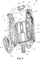
- Figures 7 to 10 show the closing steps of the carriage 10 advantageously carried out by a user by a single hand.
- the appendage 26 advantageously acts as a support on the ground.
- the carriage according to the present invention has the advantage of being foldable in a simple and quick manner with few manoeuvres and with the use of a single hand.
- the carriage according to the present invention has the advantage of having a particularly simple and light structure and of having extremely limited dimensions especially when it is in the closed configuration, so as to be easily transported and handled.
- the carriage according to the present invention has the advantage of comprising a spacious basket adapted to contain and support even heavy loads; the bottom of the basket is in fact supported by the two plate-like bodies which are articulated in a compass-like manner between the front and rear legs and which act as elements for resting and supporting the basket.
- the carriage according to the present invention has the advantage of comprising a basket that can take up various configurations depending on the transport or containment needs.
- the carriage according to the present invention has the advantage of being adapted to be used as a push frame for baby strollers and, in particular, for the strollers the seat of which consists of a car baby seat.
- the pair of plate-like bodies articulated between the front legs and the rear legs close to their lower ends and in particular at their connecting crosspiece - as well as any pair of the shaft-like bodies that form with them an articulated quadrilateral - can be adopted in itself (i.e. even regardless of the presence of the basket) on push frames of baby strollers of the book-like foldable type of the known type, the handle shafts of which can be articulated to the front or rear legs by means of a cylindrical hinge or by means of a slidable coupling.
- the convertible carriage that is book-like foldable and usable as a push frame for baby strollers as described can be modified and adapted in several manner all falling into the scope of the present invention. Moreover, all of the details can be replaced by technically equivalent elements. In practice, the material used, as well as the dimensions, can be any depending on the technical needs.
Landscapes
- Engineering & Computer Science (AREA)
- Chemical & Material Sciences (AREA)
- Combustion & Propulsion (AREA)
- Transportation (AREA)
- Mechanical Engineering (AREA)
- Health & Medical Sciences (AREA)
- Public Health (AREA)
- Carriages For Children, Sleds, And Other Hand-Operated Vehicles (AREA)
- Toys (AREA)
Claims (15)
- Umwandelbarer, buchartig faltbarer, als Schubrahmen für Kinderwägen verwendbarer Rahmen (10), umfassend:- ein Paar Vorderbeine (11), jeweils ein rechtes Vorderbein und ein linkes Vorderbein, die zueinander parallel, seitlich beabstandet und miteinander verbunden sind, um einen einzigen Körper zu bilden, und mit wenigstens einem Vorderrad (12) zum Abstützen auf dem Boden versehen sind,- ein Paar Hinterbeine (13), jeweils ein rechtes Hinterbein und ein linkes Hinterbein, die zueinander parallel, seitlich beabstandet und miteinander verbunden sind, um einen einzigen Körper zu bilden, und mit wenigstens einem Hinterrad (14) zum Abstützen auf dem Boden versehen sind, und- ein Paar Bewegungsachsen (15), jeweils eine rechte Bewegungsachse und eine linke Bewegungsachse, die zueinander parallel, seitlich beabstandet und miteinander verbunden sind, um einen einzigen Körper zu bilden, und mit wenigstens einem Griff (16) versehen sind,- wobei das Paar Hinterbeine (13) und das Paar Vorderbeine (11) um eine erste gemeinsame Scharnierachse (A) oder eine eigene, erste, getrennte Scharnierachse (A) drehbar angelenkt sind, die in einer Gelenkverbindung definiert ist, wobei die erste Scharnierachse (A) sich parallel zum Stützboden des Rahmens und rechtwinklig zur Verschiebungsrichtung (B) des Kinderwagens befindet,dadurch gekennzeichnet, dass er Folgendes umfasst:- ein Paar plattenartige Körper (22, 23), die zwischen dem Paar Vorderbeinen (11) und dem Paar Hinterbeinen (13) eingefügt, an einem Ende um eine zweite Scharnierachse (E) aneinander angelenkt und am gegenüberliegenden Ende an dem Paar Vorderbeine (11) und an dem Paar Hinterbeinen (13) jeweils um eine dritte Scharnierachse (F) und eine vierte Scharnierachse (G) angelenkt sind, wobei die Scharnierachsen zueinander parallel und getrennt sind und wobei der Rahmen einen offenen Zustand annimmt, in dem das Paar Vorderbeine (11) und das Paar Hinterbeine (13) voneinander beabstandet sind, wobei die plattenartigen Körper (22, 23) sich zwischen ihnen erstrecken und im Wesentlichen zueinander koplanar sind und die Bewegungsachsen (15) sich aufwärts und rückwärts des Paares von Vorderbeinen (11) erstrecken, und einen geschlossenen Zustand, in dem das Paar Vorderbeine (11), das Paar Hinterbeine (13) und das Paar Bewegungsachsen (15) nahe beieinander sind und sich wenigstens teilweise überlappen und die plattenartigen Körper (22, 23) nebeneinander angeordnet sind und sich wenigstens teilweise überlappen und zwischen dem Paar Vorderbeinen und dem Paar Hinterbeinen angeordnet sind, wobei, wenn der Rahmen (10) sich im offenen Zustand befindet, das Paar plattenartiger Körper (22, 23) als Stützebene zum Abstützen des Bodens (29a) eines faltenbalgartig zusammenklappbaren Korbes (29) fungiert, der zwischen dem Paar Vorderbeinen (11) und dem Paar Hinterbeinen (13) eingefügt ist und dessen oberer Rand mit dem Paar Vorderbeinen und dem Paar Hinterbeinen verbunden ist.
- Rahmen (10) nach Anspruch 1, dadurch gekennzeichnet, dass wenigstens entweder der vordere Abschnitt des oberen Randes oder ein hinterer Abschnitt des oberen Randes an einem jeweiligen Stützkörper festgelegt ist, der jeweils an dem Paar Vorderbeinen (11) oder an dem Paar Hinterbeinen (13) zwischen einer angehobenen Position, in der er jeweils aus dem Paar Vorderbeinen (11) oder aus dem Paar Hinterbeinen (13) auskragt, und einer abgesenkten Position, in der er nahe bei und im Wesentlichen koplanar jeweils zu dem Paar Vorderbeinen (11) oder zu dem Paar Hinterbeinen (13) beweglich ist.
- Rahmen (10) nach Anspruch 1 oder 2, dadurch gekennzeichnet, dass der Abstand zwischen der zweiten Scharnierachse (E) und der dritten Scharnierachse (F) verschieden von dem Abstand zwischen der zweiten Scharnierachse (E) und der vierten Scharnierachse (G) ist.
- Rahmen (10) nach Anspruch 3, dadurch gekennzeichnet, dass der Abstand zwischen der zweiten Scharnierachse (E) und der dritten Scharnierachse (F) größer als der Abstand zwischen der zweiten Scharnierachse (E) und der vierten Scharnierachse (G) ist.
- Rahmen (10) nach einem oder mehreren der vorstehenden Ansprüche, dadurch gekennzeichnet, dass die gegenüberliegenden Enden der plattenartigen Körper (22, 23) an dem Paar Vorderbeinen (11) und an dem Paar Hinterbeinen (13) jeweils in der Nähe ihrer Enden angelenkt sind, die jeweils an dem wenigstens einen Vorderrad (12) und an dem wenigstens einen Hinterrad (13) angekoppelt sind.
- Rahmen (10) nach einem oder mehreren der vorstehenden Ansprüche, dadurch gekennzeichnet, dass die gegenüberliegenden Enden der plattenartigen Körper (22, 23) an dem Paar Vorderbeinen (11) und an dem Paar Hinterbeinen (13) jeweils an einem jeweiligen Verbindungskreuzstück (17, 18) der beiden Vorderbeine (11) und der beiden Hinterbeine (13) angelenkt sind.
- Rahmen (10) nach einem oder mehreren der vorstehenden Ansprüche, dadurch gekennzeichnet, dass er ein Paar wellenartige Körper (24, 25) umfasst, die zwischen dem Paar Vorderbeinen (11) und dem Paar Hinterbeinen (13) eingefügt sind, an einem Ende um eine fünfte Scharnierachse (H) aneinander angelenkt sind und an dem gegenüberliegenden Ende jeweils an dem Paar Vorderbeinen (11) oder an dem plattenartigen Körper (22) angelenkt sind, der an dem Paar Vorderbeinen und dem Paar Hinterbeinen (13) angelenkt ist, oder an dem plattenartigen Körper (23), der an dem Paar Hinterbeinen jeweils um eine sechste Scharnierachse (I) und eine siebte Scharnierachse (L) angelenkt ist, die jeweils koinzident oder parallel zu der dritten Scharnierachse (F) zu der vierten Scharnierachse (G) ist, wobei das Paar plattenartiger Körper (22, 23) und das Paar wellenartiger Körper (24, 25) ein Gelenkviereck bilden.
- Rahmen (10) nach Anspruch 7, dadurch gekennzeichnet, dass einer der plattenartigen Körper (22, 23) oder der wellenartigen Körper (24, 25) an einem seiner Enden einen Fortsatz (26) aufweist, der, wenn der Rahmen sich in einem geschlossenen Zustand befindet, als Strebe zum Abstützen auf dem Boden dient.
- Rahmen (10) nach einem oder mehreren der Ansprüche 2 bis 8, dadurch gekennzeichnet, dass er ein Paar rohrbogenförmiger Körper (27, 28) umfasst, jeweils einen vorderen rohrbogenförmigen Körper (27) und einen hinteren rohrbogenförmigen Körper (28), die die Stützkörper bilden und deren jeweilige Scharnierenden an dem Paar Vorderbeinen (11) und dem Paar Hinterbeinen (13) jeweils um eine zehnte Scharnierachse (M) und eine elfte Scharnierachse (N) parallel zu und getrennt von den jeweiligen Scharnierachsen angelenkt sind, wobei jeder der rohrbogenförmigen Körper (27, 28) einen oberen Rand eines jeweiligen Endes des faltenbalgartig zusammenklappbaren Korbes (29) definiert und zwischen einer angehobenen Position, in der er jeweils aus dem Paar Vorderbeinen (11) und aus dem Paar Hinterbeinen (13) auskragt, und einer abgesenkten Position beweglich ist, in der er jeweils nahe bei und im Wesentlichen koplanar zu dem Paar Vorderbeinen (11) oder dem Paar Hinterbeinen (13) ist, wobei der Boden (29a) des Korbes (29) auf dem Paar plattenartiger Körper (22, 23) aufliegt, wenn der Rahmen sich in seinem offenen Zustand befindet.
- Rahmen (10) nach Anspruch 9, dadurch gekennzeichnet, dass der Korb (29) eine flexible Abdeckung umfasst, die die Wand und den Boden desselben definiert, und einen oberen umlaufenden Rand aufweist, der mit den rohrbogenförmigen Körpern (27, 28) gekoppelt ist.
- Rahmen (10) nach Anspruch 10, dadurch gekennzeichnet, dass die Abdeckung Bodenabschnitte (29a) aufweist, die an dem Paar Vorderbeinen (11) und an dem Paar Hinterbeinen (13) nahe ihrem unteren Ende (11a, 13a) gekoppelt sind.
- Rahmen (10) nach einem oder mehreren der vorstehenden Ansprüche, dadurch gekennzeichnet, dass das Paar Bewegungsachsen (15) mit dem Paar Vorderbeinen (11) mit einer Gleitbewegungskomponente in eine Richtung parallel zur Längsabwicklungsrichtung der Vorderbeine (11) beweglich gekoppelt ist und Folgendes umfasst:- ein Paar Hebel (21), jeweils einen rechten und einen linken Hebel, die ein Ende (21a) aufweisen, das jeweils an der rechten Bewegungsachse (15) und der linken Bewegungsachse (15) um eine gemeinsame achte Scharnierachse (C) angelenkt ist, und das gegenüberliegende Ende (21b) jeweils an dem rechten Hinterbein (13) und dem linken Hinterbein (13) um eine gemeinsame neunte Scharnierachse (D) angelenkt ist.
- Rahmen (10) nach einem oder mehreren der vorstehenden Ansprüche, dadurch gekennzeichnet, dass er Koppelglieder (30) zum abnehmbaren Koppeln mit einem Babyaufnahmeraum umfasst.
- Rahmen (10) nach Anspruch 13, dadurch gekennzeichnet, dass die Koppelglieder wenigstens eines der Folgenden umfassen: eine Querstange (31), die sich zwischen den Hinterbeinen oder zwischen den Vorderbeinen nahe der ersten Scharnierachse (A) zum Koppeln mit Haken- oder Kupplungselementen erstreckt, die an dem Babyaufnahmeraum vorgesehen sind, an den Vorder- oder Hinterbeinen definierte Zapfen- oder Schlitzelemente (32) oder an dem Aufnahmeraum vorgesehene, ineinandergreifende Kupplungselemente, eine sich zwischen den Vorder- oder Hinterbeinen erstreckende und mit Kupplungselementen zur gegenseitigen Kopplung mit in dem Aufnahmeraum vorgesehenen komplementären Kupplungselementen versehene Stützplatte (33).
- Kinderwagen umfassend einen Schubrahmen, mit dem ein Babyaufnahmeraum abnehmbar gekoppelt ist, dadurch gekennzeichnet, dass der Schubrahmen aus einem Rahmen (10) nach einem oder mehreren der vorstehenden Ansprüche besteht.
Applications Claiming Priority (1)
| Application Number | Priority Date | Filing Date | Title |
|---|---|---|---|
| ITUB2015A005203A ITUB20155203A1 (it) | 2015-10-19 | 2015-10-19 | Carrello convertibile, ripiegabile a libro e utilizzabile come telaio di spinta di passeggini per bambini |
Publications (2)
| Publication Number | Publication Date |
|---|---|
| EP3159239A1 EP3159239A1 (de) | 2017-04-26 |
| EP3159239B1 true EP3159239B1 (de) | 2019-01-23 |
Family
ID=55237865
Family Applications (1)
| Application Number | Title | Priority Date | Filing Date |
|---|---|---|---|
| EP16194539.9A Not-in-force EP3159239B1 (de) | 2015-10-19 | 2016-10-19 | Faltbarer rahmen für kinderwägen |
Country Status (3)
| Country | Link |
|---|---|
| EP (1) | EP3159239B1 (de) |
| CN (1) | CN206456417U (de) |
| IT (1) | ITUB20155203A1 (de) |
Families Citing this family (9)
| Publication number | Priority date | Publication date | Assignee | Title |
|---|---|---|---|---|
| NL2019268B1 (en) * | 2017-07-18 | 2019-01-30 | De Vrede Camille | Push chair carriage and push chair comprising such push chair carriage |
| US10940880B2 (en) | 2018-09-10 | 2021-03-09 | Wonderland Switzerland Ag | Stroller and basket thereof |
| CN110001737B (zh) * | 2019-04-10 | 2024-02-13 | 东莞金旺儿童用品有限公司 | 婴儿推车架 |
| CN110329337A (zh) * | 2019-08-13 | 2019-10-15 | 佘娟 | 一种基于重力平衡的防摔婴儿推车 |
| KR102176728B1 (ko) * | 2020-05-06 | 2020-11-09 | 주식회사 세이프웨이 | 폴딩형 유모차 |
| US11897534B2 (en) * | 2020-10-14 | 2024-02-13 | Graco Children's Products, Inc. | Wagon stroller, systems, and methods |
| CN112353580A (zh) * | 2020-11-06 | 2021-02-12 | 常州中进医疗器材股份有限公司 | 一种折叠拖行的轮椅 |
| NL2032195B1 (en) * | 2020-12-18 | 2023-07-17 | Royalty Bugaboo Gmbh | Foldable stroller, foldable bassinet, foldable seat, stroller and stroller and luggage system |
| CN114604308A (zh) * | 2022-02-18 | 2022-06-10 | 好孩子儿童用品有限公司 | 儿童推车 |
Family Cites Families (4)
| Publication number | Priority date | Publication date | Assignee | Title |
|---|---|---|---|---|
| US4239259A (en) * | 1979-04-06 | 1980-12-16 | Martinez Virginia R | Height adjustable infant stroller-high chair |
| DE3709712A1 (de) * | 1986-04-23 | 1987-10-29 | Perego Pines Gmbh | Verbesserter, klappbarer kinderwagen |
| NL1030332C2 (nl) * | 2005-11-01 | 2007-05-03 | Royalty Bugaboo Gmbh | Opvouwbare wagen, zoals een buggy, met losneembaar en opklapbaar zitje. |
| DE102007047702A1 (de) * | 2007-04-02 | 2008-10-30 | Victor Lang | Kinderwagen mit einem zusammenklappbaren Fahrgestell |
-
2015
- 2015-10-19 IT ITUB2015A005203A patent/ITUB20155203A1/it unknown
-
2016
- 2016-10-19 EP EP16194539.9A patent/EP3159239B1/de not_active Not-in-force
- 2016-10-19 CN CN201621272303.XU patent/CN206456417U/zh not_active Expired - Fee Related
Non-Patent Citations (1)
| Title |
|---|
| None * |
Also Published As
| Publication number | Publication date |
|---|---|
| CN206456417U (zh) | 2017-09-01 |
| EP3159239A1 (de) | 2017-04-26 |
| ITUB20155203A1 (it) | 2017-04-19 |
Similar Documents
| Publication | Publication Date | Title |
|---|---|---|
| EP3159239B1 (de) | Faltbarer rahmen für kinderwägen | |
| CN106627690B (zh) | 一种可在折叠状态和展开状态之间转换的手推车 | |
| US9821827B2 (en) | Collapsible wheeled support or carrier | |
| US8366139B2 (en) | Foldable full-featured stroller capable of minimizing the folded size of the stroller | |
| CN101870301B (zh) | 折叠式手推车 | |
| US9561816B2 (en) | Compact foldable stroller with one-handed fold control | |
| NL2011101C2 (en) | Stroller. | |
| US4681340A (en) | Child's folding pushchair | |
| US3330575A (en) | Convertible and foldable baby vehicles | |
| US7226059B1 (en) | Adaptable transport cart for use with strollers and the like | |
| US8459665B2 (en) | Foldable stroller frame | |
| NO750170L (de) | ||
| EP1967440A2 (de) | Klappbarer Kinderwagen | |
| US9266549B2 (en) | Chassis for baby pushchairs | |
| EP2700559B1 (de) | Zusammenklappbarer Kinderwagenrahmen | |
| EP3927608B1 (de) | Umwandelbares dreirad | |
| CN110723191B (zh) | 折叠儿童推车 | |
| CN110914136A (zh) | 婴儿车支架和包括这种婴儿车支架的婴儿车 | |
| CN208646946U (zh) | 一种推车 | |
| CN105346585A (zh) | 儿童推车 | |
| CN109789887B (zh) | 童车 | |
| EP1488981A1 (de) | Zusammenklappbarer Rahmen mit Rollen, insbesondere für Kinderwagen, Rollstühle oder dergleichen | |
| EP2151365A1 (de) | Fahrzeug | |
| EP2228281B1 (de) | Faltbares Gestell für Kinderwagen | |
| WO2014097217A1 (en) | Umbrella-like foldable frame for baby strollers and the like |
Legal Events
| Date | Code | Title | Description |
|---|---|---|---|
| PUAI | Public reference made under article 153(3) epc to a published international application that has entered the european phase |
Free format text: ORIGINAL CODE: 0009012 |
|
| STAA | Information on the status of an ep patent application or granted ep patent |
Free format text: STATUS: THE APPLICATION HAS BEEN PUBLISHED |
|
| AK | Designated contracting states |
Kind code of ref document: A1 Designated state(s): AL AT BE BG CH CY CZ DE DK EE ES FI FR GB GR HR HU IE IS IT LI LT LU LV MC MK MT NL NO PL PT RO RS SE SI SK SM TR |
|
| AX | Request for extension of the european patent |
Extension state: BA ME |
|
| STAA | Information on the status of an ep patent application or granted ep patent |
Free format text: STATUS: REQUEST FOR EXAMINATION WAS MADE |
|
| 17P | Request for examination filed |
Effective date: 20171024 |
|
| RBV | Designated contracting states (corrected) |
Designated state(s): AL AT BE BG CH CY CZ DE DK EE ES FI FR GB GR HR HU IE IS IT LI LT LU LV MC MK MT NL NO PL PT RO RS SE SI SK SM TR |
|
| GRAP | Despatch of communication of intention to grant a patent |
Free format text: ORIGINAL CODE: EPIDOSNIGR1 |
|
| STAA | Information on the status of an ep patent application or granted ep patent |
Free format text: STATUS: GRANT OF PATENT IS INTENDED |
|
| RIC1 | Information provided on ipc code assigned before grant |
Ipc: B62B 7/06 20060101AFI20180705BHEP Ipc: B62B 9/26 20060101ALI20180705BHEP Ipc: B62B 7/14 20060101ALI20180705BHEP |
|
| INTG | Intention to grant announced |
Effective date: 20180802 |
|
| GRAS | Grant fee paid |
Free format text: ORIGINAL CODE: EPIDOSNIGR3 |
|
| GRAA | (expected) grant |
Free format text: ORIGINAL CODE: 0009210 |
|
| STAA | Information on the status of an ep patent application or granted ep patent |
Free format text: STATUS: THE PATENT HAS BEEN GRANTED |
|
| AK | Designated contracting states |
Kind code of ref document: B1 Designated state(s): AL AT BE BG CH CY CZ DE DK EE ES FI FR GB GR HR HU IE IS IT LI LT LU LV MC MK MT NL NO PL PT RO RS SE SI SK SM TR |
|
| REG | Reference to a national code |
Ref country code: GB Ref legal event code: FG4D |
|
| REG | Reference to a national code |
Ref country code: CH Ref legal event code: EP |
|
| REG | Reference to a national code |
Ref country code: AT Ref legal event code: REF Ref document number: 1091230 Country of ref document: AT Kind code of ref document: T Effective date: 20190215 |
|
| REG | Reference to a national code |
Ref country code: IE Ref legal event code: FG4D |
|
| REG | Reference to a national code |
Ref country code: DE Ref legal event code: R096 Ref document number: 602016009415 Country of ref document: DE |
|
| REG | Reference to a national code |
Ref country code: NL Ref legal event code: MP Effective date: 20190123 |
|
| PG25 | Lapsed in a contracting state [announced via postgrant information from national office to epo] |
Ref country code: NL Free format text: LAPSE BECAUSE OF FAILURE TO SUBMIT A TRANSLATION OF THE DESCRIPTION OR TO PAY THE FEE WITHIN THE PRESCRIBED TIME-LIMIT Effective date: 20190123 |
|
| PG25 | Lapsed in a contracting state [announced via postgrant information from national office to epo] |
Ref country code: ES Free format text: LAPSE BECAUSE OF FAILURE TO SUBMIT A TRANSLATION OF THE DESCRIPTION OR TO PAY THE FEE WITHIN THE PRESCRIBED TIME-LIMIT Effective date: 20190123 Ref country code: PT Free format text: LAPSE BECAUSE OF FAILURE TO SUBMIT A TRANSLATION OF THE DESCRIPTION OR TO PAY THE FEE WITHIN THE PRESCRIBED TIME-LIMIT Effective date: 20190523 Ref country code: LT Free format text: LAPSE BECAUSE OF FAILURE TO SUBMIT A TRANSLATION OF THE DESCRIPTION OR TO PAY THE FEE WITHIN THE PRESCRIBED TIME-LIMIT Effective date: 20190123 Ref country code: FI Free format text: LAPSE BECAUSE OF FAILURE TO SUBMIT A TRANSLATION OF THE DESCRIPTION OR TO PAY THE FEE WITHIN THE PRESCRIBED TIME-LIMIT Effective date: 20190123 Ref country code: NO Free format text: LAPSE BECAUSE OF FAILURE TO SUBMIT A TRANSLATION OF THE DESCRIPTION OR TO PAY THE FEE WITHIN THE PRESCRIBED TIME-LIMIT Effective date: 20190423 Ref country code: PL Free format text: LAPSE BECAUSE OF FAILURE TO SUBMIT A TRANSLATION OF THE DESCRIPTION OR TO PAY THE FEE WITHIN THE PRESCRIBED TIME-LIMIT Effective date: 20190123 Ref country code: SE Free format text: LAPSE BECAUSE OF FAILURE TO SUBMIT A TRANSLATION OF THE DESCRIPTION OR TO PAY THE FEE WITHIN THE PRESCRIBED TIME-LIMIT Effective date: 20190123 |
|
| REG | Reference to a national code |
Ref country code: AT Ref legal event code: MK05 Ref document number: 1091230 Country of ref document: AT Kind code of ref document: T Effective date: 20190123 |
|
| PG25 | Lapsed in a contracting state [announced via postgrant information from national office to epo] |
Ref country code: BG Free format text: LAPSE BECAUSE OF FAILURE TO SUBMIT A TRANSLATION OF THE DESCRIPTION OR TO PAY THE FEE WITHIN THE PRESCRIBED TIME-LIMIT Effective date: 20190423 Ref country code: GR Free format text: LAPSE BECAUSE OF FAILURE TO SUBMIT A TRANSLATION OF THE DESCRIPTION OR TO PAY THE FEE WITHIN THE PRESCRIBED TIME-LIMIT Effective date: 20190424 Ref country code: RS Free format text: LAPSE BECAUSE OF FAILURE TO SUBMIT A TRANSLATION OF THE DESCRIPTION OR TO PAY THE FEE WITHIN THE PRESCRIBED TIME-LIMIT Effective date: 20190123 Ref country code: IS Free format text: LAPSE BECAUSE OF FAILURE TO SUBMIT A TRANSLATION OF THE DESCRIPTION OR TO PAY THE FEE WITHIN THE PRESCRIBED TIME-LIMIT Effective date: 20190523 Ref country code: LV Free format text: LAPSE BECAUSE OF FAILURE TO SUBMIT A TRANSLATION OF THE DESCRIPTION OR TO PAY THE FEE WITHIN THE PRESCRIBED TIME-LIMIT Effective date: 20190123 Ref country code: HR Free format text: LAPSE BECAUSE OF FAILURE TO SUBMIT A TRANSLATION OF THE DESCRIPTION OR TO PAY THE FEE WITHIN THE PRESCRIBED TIME-LIMIT Effective date: 20190123 |
|
| REG | Reference to a national code |
Ref country code: DE Ref legal event code: R097 Ref document number: 602016009415 Country of ref document: DE |
|
| PG25 | Lapsed in a contracting state [announced via postgrant information from national office to epo] |
Ref country code: SK Free format text: LAPSE BECAUSE OF FAILURE TO SUBMIT A TRANSLATION OF THE DESCRIPTION OR TO PAY THE FEE WITHIN THE PRESCRIBED TIME-LIMIT Effective date: 20190123 Ref country code: CZ Free format text: LAPSE BECAUSE OF FAILURE TO SUBMIT A TRANSLATION OF THE DESCRIPTION OR TO PAY THE FEE WITHIN THE PRESCRIBED TIME-LIMIT Effective date: 20190123 Ref country code: RO Free format text: LAPSE BECAUSE OF FAILURE TO SUBMIT A TRANSLATION OF THE DESCRIPTION OR TO PAY THE FEE WITHIN THE PRESCRIBED TIME-LIMIT Effective date: 20190123 Ref country code: AL Free format text: LAPSE BECAUSE OF FAILURE TO SUBMIT A TRANSLATION OF THE DESCRIPTION OR TO PAY THE FEE WITHIN THE PRESCRIBED TIME-LIMIT Effective date: 20190123 Ref country code: DK Free format text: LAPSE BECAUSE OF FAILURE TO SUBMIT A TRANSLATION OF THE DESCRIPTION OR TO PAY THE FEE WITHIN THE PRESCRIBED TIME-LIMIT Effective date: 20190123 Ref country code: EE Free format text: LAPSE BECAUSE OF FAILURE TO SUBMIT A TRANSLATION OF THE DESCRIPTION OR TO PAY THE FEE WITHIN THE PRESCRIBED TIME-LIMIT Effective date: 20190123 Ref country code: IT Free format text: LAPSE BECAUSE OF FAILURE TO SUBMIT A TRANSLATION OF THE DESCRIPTION OR TO PAY THE FEE WITHIN THE PRESCRIBED TIME-LIMIT Effective date: 20190123 |
|
| PG25 | Lapsed in a contracting state [announced via postgrant information from national office to epo] |
Ref country code: SM Free format text: LAPSE BECAUSE OF FAILURE TO SUBMIT A TRANSLATION OF THE DESCRIPTION OR TO PAY THE FEE WITHIN THE PRESCRIBED TIME-LIMIT Effective date: 20190123 |
|
| PLBE | No opposition filed within time limit |
Free format text: ORIGINAL CODE: 0009261 |
|
| STAA | Information on the status of an ep patent application or granted ep patent |
Free format text: STATUS: NO OPPOSITION FILED WITHIN TIME LIMIT |
|
| PG25 | Lapsed in a contracting state [announced via postgrant information from national office to epo] |
Ref country code: AT Free format text: LAPSE BECAUSE OF FAILURE TO SUBMIT A TRANSLATION OF THE DESCRIPTION OR TO PAY THE FEE WITHIN THE PRESCRIBED TIME-LIMIT Effective date: 20190123 |
|
| 26N | No opposition filed |
Effective date: 20191024 |
|
| PG25 | Lapsed in a contracting state [announced via postgrant information from national office to epo] |
Ref country code: SI Free format text: LAPSE BECAUSE OF FAILURE TO SUBMIT A TRANSLATION OF THE DESCRIPTION OR TO PAY THE FEE WITHIN THE PRESCRIBED TIME-LIMIT Effective date: 20190123 |
|
| PG25 | Lapsed in a contracting state [announced via postgrant information from national office to epo] |
Ref country code: TR Free format text: LAPSE BECAUSE OF FAILURE TO SUBMIT A TRANSLATION OF THE DESCRIPTION OR TO PAY THE FEE WITHIN THE PRESCRIBED TIME-LIMIT Effective date: 20190123 |
|
| REG | Reference to a national code |
Ref country code: DE Ref legal event code: R119 Ref document number: 602016009415 Country of ref document: DE |
|
| PG25 | Lapsed in a contracting state [announced via postgrant information from national office to epo] |
Ref country code: MC Free format text: LAPSE BECAUSE OF FAILURE TO SUBMIT A TRANSLATION OF THE DESCRIPTION OR TO PAY THE FEE WITHIN THE PRESCRIBED TIME-LIMIT Effective date: 20190123 |
|
| REG | Reference to a national code |
Ref country code: CH Ref legal event code: PL |
|
| PG25 | Lapsed in a contracting state [announced via postgrant information from national office to epo] |
Ref country code: LU Free format text: LAPSE BECAUSE OF NON-PAYMENT OF DUE FEES Effective date: 20191019 Ref country code: DE Free format text: LAPSE BECAUSE OF NON-PAYMENT OF DUE FEES Effective date: 20200501 Ref country code: LI Free format text: LAPSE BECAUSE OF NON-PAYMENT OF DUE FEES Effective date: 20191031 Ref country code: CH Free format text: LAPSE BECAUSE OF NON-PAYMENT OF DUE FEES Effective date: 20191031 |
|
| REG | Reference to a national code |
Ref country code: BE Ref legal event code: MM Effective date: 20191031 |
|
| PG25 | Lapsed in a contracting state [announced via postgrant information from national office to epo] |
Ref country code: BE Free format text: LAPSE BECAUSE OF NON-PAYMENT OF DUE FEES Effective date: 20191031 |
|
| PG25 | Lapsed in a contracting state [announced via postgrant information from national office to epo] |
Ref country code: IE Free format text: LAPSE BECAUSE OF NON-PAYMENT OF DUE FEES Effective date: 20191019 Ref country code: FR Free format text: LAPSE BECAUSE OF NON-PAYMENT OF DUE FEES Effective date: 20191031 |
|
| PG25 | Lapsed in a contracting state [announced via postgrant information from national office to epo] |
Ref country code: CY Free format text: LAPSE BECAUSE OF FAILURE TO SUBMIT A TRANSLATION OF THE DESCRIPTION OR TO PAY THE FEE WITHIN THE PRESCRIBED TIME-LIMIT Effective date: 20190123 |
|
| GBPC | Gb: european patent ceased through non-payment of renewal fee |
Effective date: 20201019 |
|
| PG25 | Lapsed in a contracting state [announced via postgrant information from national office to epo] |
Ref country code: HU Free format text: LAPSE BECAUSE OF FAILURE TO SUBMIT A TRANSLATION OF THE DESCRIPTION OR TO PAY THE FEE WITHIN THE PRESCRIBED TIME-LIMIT; INVALID AB INITIO Effective date: 20161019 Ref country code: MT Free format text: LAPSE BECAUSE OF FAILURE TO SUBMIT A TRANSLATION OF THE DESCRIPTION OR TO PAY THE FEE WITHIN THE PRESCRIBED TIME-LIMIT Effective date: 20190123 |
|
| PG25 | Lapsed in a contracting state [announced via postgrant information from national office to epo] |
Ref country code: GB Free format text: LAPSE BECAUSE OF NON-PAYMENT OF DUE FEES Effective date: 20201019 |
|
| PG25 | Lapsed in a contracting state [announced via postgrant information from national office to epo] |
Ref country code: MK Free format text: LAPSE BECAUSE OF FAILURE TO SUBMIT A TRANSLATION OF THE DESCRIPTION OR TO PAY THE FEE WITHIN THE PRESCRIBED TIME-LIMIT Effective date: 20190123 |