EP3156555B2 - Aufhängung für dämmmaterial mit umkehrbarer verriegelung - Google Patents
Aufhängung für dämmmaterial mit umkehrbarer verriegelung Download PDFInfo
- Publication number
- EP3156555B2 EP3156555B2 EP16190455.2A EP16190455A EP3156555B2 EP 3156555 B2 EP3156555 B2 EP 3156555B2 EP 16190455 A EP16190455 A EP 16190455A EP 3156555 B2 EP3156555 B2 EP 3156555B2
- Authority
- EP
- European Patent Office
- Prior art keywords
- shaft
- latch
- hanger
- mount
- lock
- Prior art date
- Legal status (The legal status is an assumption and is not a legal conclusion. Google has not performed a legal analysis and makes no representation as to the accuracy of the status listed.)
- Active
Links
Images


Classifications
-
- E—FIXED CONSTRUCTIONS
- E04—BUILDING
- E04D—ROOF COVERINGS; SKY-LIGHTS; GUTTERS; ROOF-WORKING TOOLS
- E04D13/00—Special arrangements or devices in connection with roof coverings; Protection against birds; Roof drainage ; Sky-lights
- E04D13/16—Insulating devices or arrangements in so far as the roof covering is concerned, e.g. characterised by the material or composition of the roof insulating material or its integration in the roof structure
- E04D13/1606—Insulation of the roof covering characterised by its integration in the roof structure
- E04D13/1612—Insulation of the roof covering characterised by its integration in the roof structure the roof structure comprising a supporting framework of roof purlins or rafters
- E04D13/1637—Insulation of the roof covering characterised by its integration in the roof structure the roof structure comprising a supporting framework of roof purlins or rafters the roof purlins or rafters being mainly insulated from the interior, e.g. the insulating material being fixed under or suspended from the supporting framework
-
- E—FIXED CONSTRUCTIONS
- E04—BUILDING
- E04F—FINISHING WORK ON BUILDINGS, e.g. STAIRS, FLOORS
- E04F13/00—Coverings or linings, e.g. for walls or ceilings
- E04F13/07—Coverings or linings, e.g. for walls or ceilings composed of covering or lining elements; Sub-structures therefor; Fastening means therefor
- E04F13/08—Coverings or linings, e.g. for walls or ceilings composed of covering or lining elements; Sub-structures therefor; Fastening means therefor composed of a plurality of similar covering or lining elements
- E04F13/0801—Separate fastening elements
- E04F13/0803—Separate fastening elements with load-supporting elongated furring elements between wall and covering elements
- E04F13/0805—Separate fastening elements with load-supporting elongated furring elements between wall and covering elements with additional fastening elements between furring elements and the wall
-
- F—MECHANICAL ENGINEERING; LIGHTING; HEATING; WEAPONS; BLASTING
- F16—ENGINEERING ELEMENTS AND UNITS; GENERAL MEASURES FOR PRODUCING AND MAINTAINING EFFECTIVE FUNCTIONING OF MACHINES OR INSTALLATIONS; THERMAL INSULATION IN GENERAL
- F16B—DEVICES FOR FASTENING OR SECURING CONSTRUCTIONAL ELEMENTS OR MACHINE PARTS TOGETHER, e.g. NAILS, BOLTS, CIRCLIPS, CLAMPS, CLIPS OR WEDGES; JOINTS OR JOINTING
- F16B5/00—Joining sheets or plates, e.g. panels, to one another or to strips or bars parallel to them
- F16B5/06—Joining sheets or plates, e.g. panels, to one another or to strips or bars parallel to them by means of clamps or clips
- F16B5/0607—Joining sheets or plates, e.g. panels, to one another or to strips or bars parallel to them by means of clamps or clips joining sheets or plates to each other
- F16B5/0621—Joining sheets or plates, e.g. panels, to one another or to strips or bars parallel to them by means of clamps or clips joining sheets or plates to each other in parallel relationship
- F16B5/065—Joining sheets or plates, e.g. panels, to one another or to strips or bars parallel to them by means of clamps or clips joining sheets or plates to each other in parallel relationship the plates being one on top of the other and distanced from each other, e.g. by using protrusions to keep contact and distance
-
- F—MECHANICAL ENGINEERING; LIGHTING; HEATING; WEAPONS; BLASTING
- F16—ENGINEERING ELEMENTS AND UNITS; GENERAL MEASURES FOR PRODUCING AND MAINTAINING EFFECTIVE FUNCTIONING OF MACHINES OR INSTALLATIONS; THERMAL INSULATION IN GENERAL
- F16B—DEVICES FOR FASTENING OR SECURING CONSTRUCTIONAL ELEMENTS OR MACHINE PARTS TOGETHER, e.g. NAILS, BOLTS, CIRCLIPS, CLAMPS, CLIPS OR WEDGES; JOINTS OR JOINTING
- F16B7/00—Connections of rods or tubes, e.g. of non-circular section, mutually, including resilient connections
- F16B7/20—Connections of rods or tubes, e.g. of non-circular section, mutually, including resilient connections using bayonet connections
-
- F—MECHANICAL ENGINEERING; LIGHTING; HEATING; WEAPONS; BLASTING
- F16—ENGINEERING ELEMENTS AND UNITS; GENERAL MEASURES FOR PRODUCING AND MAINTAINING EFFECTIVE FUNCTIONING OF MACHINES OR INSTALLATIONS; THERMAL INSULATION IN GENERAL
- F16B—DEVICES FOR FASTENING OR SECURING CONSTRUCTIONAL ELEMENTS OR MACHINE PARTS TOGETHER, e.g. NAILS, BOLTS, CIRCLIPS, CLAMPS, CLIPS OR WEDGES; JOINTS OR JOINTING
- F16B11/00—Connecting constructional elements or machine parts by sticking or pressing them together, e.g. cold pressure welding
- F16B11/006—Connecting constructional elements or machine parts by sticking or pressing them together, e.g. cold pressure welding by gluing
-
- F—MECHANICAL ENGINEERING; LIGHTING; HEATING; WEAPONS; BLASTING
- F16—ENGINEERING ELEMENTS AND UNITS; GENERAL MEASURES FOR PRODUCING AND MAINTAINING EFFECTIVE FUNCTIONING OF MACHINES OR INSTALLATIONS; THERMAL INSULATION IN GENERAL
- F16B—DEVICES FOR FASTENING OR SECURING CONSTRUCTIONAL ELEMENTS OR MACHINE PARTS TOGETHER, e.g. NAILS, BOLTS, CIRCLIPS, CLAMPS, CLIPS OR WEDGES; JOINTS OR JOINTING
- F16B5/00—Joining sheets or plates, e.g. panels, to one another or to strips or bars parallel to them
- F16B5/06—Joining sheets or plates, e.g. panels, to one another or to strips or bars parallel to them by means of clamps or clips
- F16B5/0607—Joining sheets or plates, e.g. panels, to one another or to strips or bars parallel to them by means of clamps or clips joining sheets or plates to each other
- F16B5/0614—Joining sheets or plates, e.g. panels, to one another or to strips or bars parallel to them by means of clamps or clips joining sheets or plates to each other in angled relationship
-
- F—MECHANICAL ENGINEERING; LIGHTING; HEATING; WEAPONS; BLASTING
- F16—ENGINEERING ELEMENTS AND UNITS; GENERAL MEASURES FOR PRODUCING AND MAINTAINING EFFECTIVE FUNCTIONING OF MACHINES OR INSTALLATIONS; THERMAL INSULATION IN GENERAL
- F16B—DEVICES FOR FASTENING OR SECURING CONSTRUCTIONAL ELEMENTS OR MACHINE PARTS TOGETHER, e.g. NAILS, BOLTS, CIRCLIPS, CLAMPS, CLIPS OR WEDGES; JOINTS OR JOINTING
- F16B5/00—Joining sheets or plates, e.g. panels, to one another or to strips or bars parallel to them
- F16B5/10—Joining sheets or plates, e.g. panels, to one another or to strips or bars parallel to them by means of bayonet connections
Definitions
- the present invention also relates to a member for holding at least one panel of thermally insulating material comprising at least one such hanger associated with a furring covering its end not fixed to the frame as well as a frame carrying an insulation assembly comprising at least two panels of insulating material held by such hangers.
- the lock performs a locking action of the cup on the rod, the lock and the cup having a respective central recess for the passage of the rod inside them.
- the lock ensures that the cup is blocked on the rod in the position holding the insulation panel plugged onto this rod.
- the document FR-2 925 929 describes a hanger according to the preamble of claim 1.
- the problem underlying the present invention for a hanger for an insulating material panel comprising a rod, a cup and a lock is to guarantee reversibility of the locking configuration, and to propose a locking mode which better and simply meets the assembly/disassembly constraints which arise for the installer.
- a hanger is provided as defined in claim 1 (so that in this locking configuration, the respective positions of the cup and the lock are fixed relative to the rod).
- the lock has, at least partially at its periphery, a groove for insertion into a furring, whereby the hanger, which has only three parts, is suitable for mounting an internal facing which can be removed.
- Locking is done by pivoting the lock relative to the longitudinal axis of the rod, advantageously by a quarter turn and unlocking is done in the other direction.
- the clipping means inside the cup are three in number, symmetrically distributed at 120° all around the central recess of the cup. The clipping force is then equally distributed all around the central recess passing through the cup.
- the three clips arranged at 120° center the cup at the time of assembly and ensure the maintenance of the insulation panel mounted on the rod.
- the rod is made of injected polyamide with 50% fiberglass
- the cup is made of injected copolymer polypropylene
- the lock is made of polyamide 66 with 30% fiberglass.
- At least one substantially planar annular face, defined by the cup and/or by the lock has an adhesive layer and is adapted to be stuck against a corresponding annular face of a film skewered by the rod.
- a film for example a vapor barrier
- Such an arrangement makes it possible to place a film, for example a vapor barrier, between the cup and the lock, by piercing this film with the rod then surrounding the perforation with an annular contact zone which can be impermeable at least to liquid water.
- a film separated from the insulation material by the cup, can thus be held parallel to a layer of thermal insulation.
- the substantially flat annular face defined by the cup and/or by the lock, is adapted to be placed with a bearing pressure against a corresponding annular face of the film.
- the lock when the lock has an elongated shape serving as an extension to the lock, a space is cleared between the cup and the furring all around the elongated shape, this space serving as a passage for various elements such as electrical ducts, VMC or others.
- a framework carrying an insulation assembly comprising at least two panels of insulation material, characterized in that it comprises at least one such member comprising at least two hangers, the second ends of said at least two hangers being arranged spaced apart along the length of the furring while the first ends of said at least two hangers are fixed to a respective element forming part of or being secured to the framework, the rods said at least two hangers extending parallel to each other, a respective panel of said at least two panels of material being skewered by each hanger by being interposed between the first end of the hanger and its cup, the cup pressing on the panel, said at least two panels of material being adjacent to each other.
- each hooked panel resting at least partially on two support panels. This allows double insulation with two layers of insulation material panels at the same time as support of the hooked panels on support panels.
- a plastic film covers said at least two panels inserted between the cup and the lock of each hanger, the plastic film being pierced by each rod of the hangers. This reinforces the sealing of the assembly and its insulation.
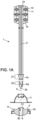
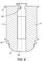
- the present invention relates to a hanger 1 intended for holding insulation material 20 on a frame.
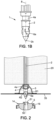
- the insulation material 20 ( Figure 2 ) is advantageously wound in the form of a coiled strip and previously cut into rectangular panels. It is such rectangular panels which are skewered in a respective hanger 1 according to the present invention, this hanger 1 essentially comprising a rod 2, a cup 3 and a lock 5, as will now be detailed.
- the hanger 1 comprises a rod 2 of which a first end 2a is intended to be fixed to the frame, advantageously by a plate 10. It is possible to have several types of hangers 1 with different rods 2 depending on the thickness of the insulation material 20 used.
- a rod 2 may have a length of 200, 280, 360 and 440 mm taking into account a 40 mm plate 10 arranged at the first end 2a of the rod 2.
- Rod 2 can be made of 50% fiberglass injected polyamide. A possible cross section of rod 2 can ensure excellent rigidity and good shock resistance, including for the longest version of rod 2, i.e. 440 mm.
- the hanger 1 also comprises a cup 3 fitted around the rod 2 and secured to the rod 2 in the vicinity of a second end 2b by first securing means 4 cooperating with complementary securing means 4a carried by the rod 2.
- the cup 3 can be made of injected copolymer polypropylene.
- the cup 3 can optionally be flared, here in the shape of a bell with an annular bell top.
- the cup 3 has a central recess 3a for the passage of the rod 2 on its side facing the first end 2a of the rod 2 and a collar 3b on its side facing the second end 2b of the rod 2.
- the bell top of the cup 3 crossed by the central recess 3a has teeth 13 around this central recess 3a.
- a lock 5 is fitted around the rod 2 while being closer to the second end 2b than the cup 3.
- the lock 5 comprises second securing means 6 with the rod 2 cooperating with second complementary securing means 6a carried by the rod 2.
- the cup 3 is held in a first receiving zone Z1 ( Figure 1 ) predefined area of the rod 2, which includes for example a circumferential groove 4a, while the lock 5 is blocked in a second predefined receiving zone Z2 of the rod 2, here axially spaced from the first receiving zone Z1.
- the cup 3 can be held in position by simply clipping into the groove 4a, as clearly visible on the Figure 2 .
- the lock 5 performs a locking action of the cup 3 on the rod 2, by pressing axially against an external face of the cup 3.
- the lock 5 may be made of rigid material (without any flexible part), for example polyamide 66 with 30% glass fiber.
- the lock 5 is here of the non-threaded type to engage on the rod 2.
- the second securing means 6 are formed on the lock 5 on the side of a base 14 of this lock 5 and are inserted into the second receiving zone Z2 without it being necessary to exert a rotation of more than half a turn.
- the cup 3 and the lock 5 have a respective central recess 3a, 5a for the passage of the rod 2 inside them and are therefore carried around the rod 2 of the hanger 1 along a longitudinal axis 8 of the rod 2.
- the collar 3b of the cup 3 is opposite and rests against the base 14 of the lock 5, where appropriate with the incorporation of a plastic film 35 between them.
- the film 35 can be stretched and fixed between the thermal insulation material 20 and the lock 5 typically serving as support for an interior facing. In this case, the film 35 can be pinched in an annular zone.
- At least one cam surface 50 is provided, here on the lock 5, to provide guidance in a bayonet-type connection, so that, during a relative rotation between the lock 5 and the rod 2 to achieve the locking configuration, a tightening in the direction of the longitudinal axis 8 is created and/or accentuated between an annular portion of the lock 5, preferably the base 14, and a facing annular portion which belongs to the cup 3. In the non-limiting example of the Figure 2 , this clamping allows a pinching of the film 35.
- the cam surface can alternatively be provided on the rod 2 in order to obtain the same effect.
- the second receiving zone Z2 there is a first face and a second face, opposite the first face, which are separated from each other along the circumference of the rod 2 by two reliefs R1, R2 which project radially outwards on the rod 2.
- These two reliefs R1, R2 form stop stops to limit to a quarter turn the relative rotation of the lock 5 with respect to the rod 2 when the second securing means 6 have been inserted into the second receiving zone Z2.
- the first and second faces are further delimited by front and rear stops. It is understood that the second securing means 6 can be both blocked in sliding by the front and rear stops and blocked in a direction of rotation due to the engagement against the reliefs R1, R2.
- the second securing means 6 are removable securing means allowing subsequent disassembly of the lock 5 from the rod 2, which allows the hanger 1 to be completely recovered for reuse.
- connection of the lock 5 with the rod 2 is carried out by pivoting the lock 5 relative to to the longitudinal axis 8 of the rod 2 extending between the two ends 2a, 2b of the rod 2.
- a clamping between the lock 5 and the cup 3 may be preferred.
- the cup 3 thus locked on the rod 2 by the lock 5 holds the insulation panel 20 hooked onto the rod 2 against falling under the action of gravity, the hanger 1 frequently being in a vertical or close to vertical position.
- the cup 3 is clipped or fixed in a robust manner to the rod 2 (here in a groove 4a having a significant depth, greater than 1 mm).
- the second removable securing means 6 comprise at least one groove 6 into which at least two lugs 6a (lugs of a bayonet connection) formed on the rod 2 penetrate as second complementary removable securing means or vice versa.
- the lugs 6a carried by the rod 2 penetrate into the groove(s) 6 by pivoting the lock 5 relative to the longitudinal axis 8 of the rod 2.
- the groove(s) 6 may be associated with an introduction ramp 9 for guiding said at least two bayonet lugs 6a towards the groove 6.
- the locking of the lock 5 on the rod 2 is thus improved.
- Each groove 6 is delimited at the top by the edge of an internal relief 51 which projects inwards from a cylindrical face 52 delimiting the central recess 5a.
- the upwardly tapered shape of each internal relief 51 allows to define at least one introduction ramp 9.
- Two adjacent tooth edges 13 can form a 90° angle with each other.
- a high number of deep teeth 13 also increases the hold.
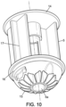
- the elongated shape 17 may be a cylindrical shape or include vertical ribs, advantageously two peripheral ribs facing each other on the lock 5 in the form of plates, therefore not producing a closed part. It is this latter embodiment which is shown in the Figure 10 .
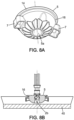
- Such a holding member may however contain several hangers 1 whose respective locks 5 are housed in a furring.
- the lock 5 of each hanger 1 may be introduced into a substantially rectilinear and elongated furring having, over its entire length, two longitudinal edges curved at 90° defining between them a furring width and having their free ends curved towards each other.
- This width of the furring 40 is equivalent to the diameter of the base 14 of the lock 5 with in addition sufficient play for the introduction of the lock 5, the base 14 of the lock 5 being the part of the lock 5 oriented towards the cup 3.
- the lock 5 may have at least partially at its periphery a groove 16 for the introduction into its interior of the free ends curved towards each other of the two longitudinal edges curved at 90° of the furring.
- the lock 5 being provided with ears 7, the introduction of the lock 5 into the furring 40 is only possible when the ears 7, as means 7 for preventing further assembly of the hanger 1, are oriented along the length of the furring.
- ears 7 of the lock(s) 5 protruding laterally relative to the furring 40 prevent further assembly of the hanger 1 by preventing the introduction of the lock(s) 5 into the furring, which corresponds to a lock 5 not pivoted relative to the longitudinal axis 8 of the rod 2, therefore not locked.
- a lock 5 pivoted to be locked for example by a quarter turn or three-quarter turn, has, when the lock 5 is introduced into the furring, its ears 7 oriented in the length of the furring 40, therefore not preventing this introduction because, so to speak, in a retracted position relative to the furring.
- the lock 5 having an elongated shape 17 serving as an extension to the lock 5, a space is cleared between the cup 3 and the furring all around the elongated shape 17, this space serving as a passage for various elements such as electrical ducts, VMC or others.
- the present invention also relates to a frame or a construction element carrying an insulation assembly comprising at least two panels of insulation material with at least two hangers 1 and a furring receiving the respective locks 5 of the two hangers 1.
- the second ends 2b of said at least two hangers 1 are arranged spaced apart along the length of the furring, for example with a spacing of the width of an insulation panel.
- the first ends of the two hangers 1 are fixed to a respective element forming part of or being secured to the frame, for example a roof rafter.
- the rods 2 of the two hangers 1 extend parallel to each other.
- a thermal insulation panel of the two panels is respectively mounted by a hanger 1 while being inserted by its thickness between the portion extending the plate 10 after the first end 2a of the hanger 1 and its cup 3.
- the cup 3 is locked by the lock 5 and rests against the panel, and the two panels of material mounted by a respective hanger are adjacent to each other.
- each insulation panel is held by the cup 3 of its hanger 1 under the action of the means for securing the cup 3 with the rod 2.
- Such an assembly can comprise more than two panels, advantageously as many panels as are needed to cover the entire roof.
- empty spaces may remain.
- one or more insulation panels known as support panels may be introduced into the empty space or spaces, each panel resting at least partially on two support panels. There are then two layers of insulation panels, which reinforces the insulation.
- the hangers 1 can be spaced the width of a panel.
- the junction of two hooked insulation panels is then made above the middle of a support panel, which is very favorable for maintaining good insulation.
- a film 35 can cover the skewered panels, the film 35 being arranged between the cup 3 and the lock 5 of each hanger 1, the film 35 being pierced by each rod 2 of the hangers 1, thus ensuring overall sealing of the assembly.
- a mechanical blocking solution can be provided between two surfaces, as illustrated for example on the figures 2 And 5B .
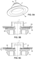
- the pinching between two substantially flat surfaces is replaced by an arrangement of reliefs, here annular, which can make it possible to fold or pinch a film 35 in several concentric zones.
- annular reliefs R3 of the cup 3 and annular reliefs R5 of the lock 5, in the locking configuration makes it possible to obtain close folds which have the effect of stretching the film 35 and obtaining a seal around the perforated zone.
- the film 35 is laid by sticking to each cup 3 by a simple adhesive strip or layer 33.
- the adhesive strip or layer 33 is typically coated with a protective cover to be removed in the case of laying a plastic film 35 such as a vapor barrier or similar film (laying which is typically carried out after the installation of the insulation material 20 and the cup 3).
- the adhesive layer 33 is here defined by a layer of adhesive material deposited on at least one substantially flat annular face of this cup 3, here on the collar 3b.
- the continuous annular arrangement of the adhesive layer 33 makes it possible to produce, near the rod 2, an annular sealing contact between the film 35 and the cup 3.
- the size of the opening around the rod 2 is thus limited. Controlling the width of the opening made by perforation makes it possible to limit, or even eliminate, the circulation of air or vapor through the skewering opening of the film 35.
- an axial spacing e of less than 5 or 10 mm is provided for example between the base 14 of the lock 5 and the cup 3 provided with the adhesive layer 33.
- This axial spacing e can be much less than the thickness of the insulating material 20 and makes it possible to avoid pinching the film 35 or causing a tear in or near the glued annular portion of the film 35.
- the lock 5 may include this type of adhesive layer and/or be attached with a bearing pressure against a corresponding annular face of the film 35.
- the present invention relates to a method of mounting an insulation assembly comprising at least two panels of insulation material on a frame as previously described.
- This method comprises the step of fixing the hangers 1 at various points of the frame, the rods 2 of said at least two hangers 1 extending parallel. Said at least two hangers 1 are then aligned so that the rods 2 protrude from the frame by the same length, given that they must receive the same thickness of thermal insulation panels.
- the lock 5 is put in place, if necessary, after inserting a protective film 35 common to all the rods 2 between each cup 3 and each lock 5. Then, the lock 5 is secured to each rod 2 by pivoting, for example a quarter turn, the lock 5 relative to the longitudinal axis 8 of the rod 2 to lock each lock 5 on its hanger 1.
- This pivoting causes the engagement of second securing means 6 carried by the lock 5 with second removable securing means 6 carried by the rod 2 of each hanger 1, allowing subsequent disassembly of the lock 5 from the rod 2 by reverse pivoting.
- Unlocking can be easily carried out by pivoting the lock 5 in the opposite direction to return to the initial position of the lock 5.
- the means of securing the lock 5 are in no way damaged by such unlocking which is carried out without effort.
- a hanger 1 according to the present invention is designed to provide under-roof insulation with the guarantee of perfect airtightness.
- the rod 2 of the hanger 1 is made exclusively by injection of a high-performance technical polymer, which increases its rigidity and makes it possible not to use a metallic element for its manufacture, which could have created thermal conduction.
- the lock 5 is assembled to the rod 2 by a bayonet system, which gives it high mechanical resistance and the possibility of easy and non-destructive disassembly of the means of securing between the lock 5 and the rod 2 of the hanger 1.
- This bayonet lug system 6a is more resistant than a clipping system as proposed by the state of the art.
- the cup 3 can have the widest possible bearing surface against the insulating panel, which can be double that of a cup of a hanger according to the state of the art.
- a particularly advantageous characteristic of the present invention is that means for preventing further assembly such as ears 7 can prevent the use of the hanger 1. For example, due to the ears 7 in the prohibiting position when the hanger 1 is not locked, the furring 40 cannot receive such an unlocked hanger 1 inside it.
- the holding collars 12 surrounding the bores 11 of the plate 10 of the hanger 1 allow the screws to be pre-positioned and free at least the fingers of the fitter who no longer needs to hold the screws.
Landscapes
- Engineering & Computer Science (AREA)
- General Engineering & Computer Science (AREA)
- Architecture (AREA)
- Mechanical Engineering (AREA)
- Civil Engineering (AREA)
- Structural Engineering (AREA)
- Clamps And Clips (AREA)
Claims (13)
- Aufhängung (1), welche dazu vorgesehen ist, Isoliermaterial an einem Gebälk zu halten, umfassend:- eine Stange (2), deren erstes Ende (2a) dazu vorgesehen ist, an dem Gebälk befestigt zu sein,- eine Manschette (3), welche um die Stange (2) herum angebracht und mit der Stange (2) benachbart zu einem zweiten Ende (2b) der Stange (2) durch erste Verbindungsmittel (4) verbunden ist, welche an der Manschette (3) gebildet sind, indem sie mit komplementären Befestigungsmitteln (4a) zusammenwirken, welche an der Stange (2) gebildet sind,- einen Riegel (5), welcher um die Stange (2) herum angebracht ist, wobei er näher an dem zweiten Ende (2b) ist als die Manschette (3), wobei der Riegel (5) zweite Verbindungsmittel (6) mit der Stange (2) umfasst, welche in einer Verriegelungskonfiguration mit zweiten komplementären Befestigungsmitteln (6a) eingreifen, welche an der Stange (2) gebildet sind, wobei die Verbindung des Riegels (5) mit der Stange (2) durch ein Schwenken des Riegels (5) gegenüber einer longitudinalen Achse (8) der Stange (2) bewirkt wird, welche sich zwischen den beiden Enden (2a, 2b) der Stange (2) erstreckt,wobei der Riegel (5) und die Manschette (3) eine jeweilige zentrale Aussparung (3a 5a) für einen Durchgang der Stange in ihrem Inneren aufweisen, wobei der Riegel (5) wenigstens teilweise in seinem Umfang eine Nut (16) für das Einführen in sein Inneres von freien Enden aufweist, welche zueinander von den beiden gebogenen longitudinalen Rändern einer Polsterung (40) um 90° gebogen sind,dadurch gekennzeichnet, dass in der Verriegelungskonfiguration der Aufhängung (1) die Manschette (3) in einer ersten vordefinierten Aufnahmezone (Z1) der Stange (2) gehalten ist, während der Riegel (5) in einer vordefinierten zweiten Aufnahmezone (Z2) der Stange (2) zum Blockieren kommt, und dass die zweiten Verbindungsmittel (6):und wobei die ersten Verbindungsmittel (4), die in der Form von Schnappmitteln innerhalb der Manschette (3) als komplementäre erste Verbindungsmittel mit einer an der Stange (2) gebildeten Nut (4a) zusammenwirken, wobei drei Schnappmittel innerhalb der Manschette vorliegen, welche symmetrisch um 120° beabstandet um die zentrale Öffnung (3a) der Manschette (3) verteilt sind.- dazu eingerichtet sind, in der vordefinierten zweiten Aufnahmezone (Z2) einzugreifen, welche von der ersten Aufnahmezone (Z1) getrennt und axial beabstandet ist, wobei sie näher zu dem zweiten Ende (2b) der Stange (2) sind, und- lösbare Verbindungsmittel sind, welche ein späteres Demontieren des Riegels (5) von der Stange (2) erlauben, und welche wenigstens einen Hals (6) umfassen, in den während des Schwenkens des Riegels (5) wenigstens zwei Zapfen (6a) einer an der Stange (2) gebildeten Verbindung vom Bajonett-Typ als zweite lösbare komplementäre Verbindungsmittel eindringen oder umgekehrt,
- Aufhängung (1) nach Anspruch 1, wobei der wenigstens eine Hals (6) einer Einführungsrampe (9) für das Führen der wenigstens zwei Bajonette (6a) in Richtung des wenigstens einen Halses (6) zugeordnet ist.
- Aufhängung (1) nach Anspruch 1 oder 2, wobei wenigstens eine Nockenfläche (50) an der Stange (2) oder an dem Riegel (5) vorgesehen ist, um eine Führung in der Verbindung vom Bajonett-Typ derart auszuführen, dass während einer relativen Rotation zwischen dem Riegel (5) und der Stange (2) zum Erreichen der Verriegelungskonfiguration eine Spannung erzeugt und/oder verstärkt wird, welche der Richtung der longitudinalen Achse folgt, zwischen:- einem ringförmigen Abschnitt des Riegels (5), vorzugsweise einer Basis (14) des Riegels (5), und- einem gegenüberliegenden ringförmigen Abschnitt (3b), welcher der Manschette (3) zugehörig ist.
- Aufhängung (1) nach einem der vorhergehenden Ansprüche, wobei das erste Ende (2a) der Stange (2) eine im Wesentlichen ebene Platte (10) aufweist, welche dazu vorgesehen ist, in Anlage gegen einen Abschnitt des Gebälks zu sein, wobei die Platte (10) Bohrungen (11) für den Durchgang von Elementen zur Befestigung an dem Gebälk aufweist, wobei jede Bohrung (11) einen Haltekragen (12) aufweist, welcher dazu vorgesehen ist, das zugeordnete Element zur Befestigung zu umgeben.
- Aufhängung (1) nach einem der vorhergehenden Ansprüche, wobei der Abschnitt der Manschette (3), welcher am innersten zu der Stange (2) ist, eine Reihe von Zähnen (13) trägt, welche in Richtung des ersten Endes (2a) der Stange (2) weisen, wenn die Manschette (3) mit der Stange (2) verbunden ist.
- Aufhängung nach einem der vorhergehenden Ansprüche, wobei wenigstens eine im Wesentlichen ebene ringförmige Fläche, welche durch die Manschette (3) und/oder durch den Riegel (5) definiert ist, eine haftfähige Schicht (33) aufweist und dazu eingerichtet ist, gegen eine entsprechende ringförmige Fläche eines Films (35) geklebt zu werden, welcher durch die Stange (2) durchbohrt ist.
- Aufhängung (1) nach einem der Ansprüche 1 bis 6, wobei der Riegel (5) eine gewölbte Form von abnehmendem kreisförmigem Querschnitt aufweist, wobei eine Basis (14) des Riegels (5), welche in Richtung der Manschette (3) orientiert ist, größer als eine Spitze (15) des Riegels (5) gegenüber der Basis (14) ist, wobei der Umfang des Riegels (5) zwei Ohren (7) trägt, welche diametral entgegengesetzt vorspringen und einerseits als Mittel zum Greifen des Riegels (5) durch die Finger eines Monteurs während seiner Positionierung an der Stange (2) und während eines Schwenkens um die longitudinale Achse (8) der Stange (2) zur Verriegelung und andererseits als Mittel zum visuellen Erkennen (7) einer Positionierung in Verriegelungsposition des Riegels (5) an der Stange mittels der Position der Ohren (7) bezüglich der longitudinalen Achse (8) der Stange (2) dienen.
- Aufhängung (1) nach einem der Ansprüche 1 bis 6, wobei der Riegel (5) an seinem Ende gegenüber der Manschette (3) eine Spitze (15) von gewölbter Form mit abnehmendem kreisförmigem Querschnitt in Richtung des entgegengesetzten Endes aufweist, sowie an seinem Ende gegenüber der Manschette (3) eine Basis (14) des Riegels (5), welche in Richtung der Manschette (3) orientiert ist, wobei eine längliche Form (17) zur Verlängerung des Riegels (5) dient, indem die Basis (14) und die Spitze (15) verbunden sind, wobei die Basis (14), die Spitze (15) und die längliche Form (17) einstückig sind.
- Einrichtung zum Halten wenigstens eines Paneels aus isolierendem Material, dadurch gekennzeichnet, dass sie eine Polsterung (40) und wenigstens eine Aufhängung (1) nach einem der beiden vorhergehenden Ansprüche umfasst, wobei in der Einrichtung der Riegel (5) von jeder Aufhängung (1) in eine im Wesentlichen geradlinige Polsterung eingeführt ist, indem sie über ihre gesamte Länge zwei um 90° gebogene longitudinale Ränder aufweist, welche zwischen einander eine Größe der Polsterung definieren und ihre freien Enden zueinander gebogen aufweisen, wobei die Größe der Polsterung äquivalent zu dem Durchmesser der Basis (14) des Riegels (5) ist, wodurch zusätzlich ein Spiel für das Einführen des Riegels (5) geschaffen ist, wobei der Riegel (5) wenigstens teilweise an seinem Umfang eine Nut (16) für das Einführen der freien zueinander gebogenen Enden der Polsterung (40) in seinem Inneren aufweist.
- Gebälk, welches eine Isolierungsanordnung trägt, welche wenigstens zwei Paneele aus isolierendem Material umfasst, dadurch gekennzeichnet, dass es wenigstens eine Einrichtung zum Halten nach dem vorhergehenden Anspruch umfasst, welche wenigstens zwei Aufhängungen (1) umfasst, wobei die zweiten Enden der wenigstens zwei Aufhängungen (1) beabstandet in der Länge der Polsterung angeordnet sind, wenn die ersten Enden der wenigstens zwei Aufhängungen (1) an einem jeweiligen Element befestigt sind, welches einen Teil des Gebälks bildet oder mit ihm verbunden ist, wobei die Stangen (2) der wenigstens zwei Aufhängungen (1) sich parallel zueinander erstrecken, wobei ein entsprechendes Paneel der wenigstens zwei Paneele aus Material durch jede Aufhängung (1) durchbohrt ist, indem sie zwischen dem ersten Ende (2a) der Aufhängung (1) und ihrer Manschette (3) eingefügt ist, wobei die Manschette (3) gegen das Paneel drückt, wobei die wenigstens zwei Paneele aus Material benachbart zueinander sind.
- Gebälk nach dem vorhergehenden Anspruch, wobei zwischen den wenigstens zwei Aufhängungen (1) ein Anlage-Isolierungspaneel eingefügt ist, wobei jedes durchbohrte Paneel wenigstens teilweise an zwei Anlagepaneelen ruht.
- Gebälk nach einem der beiden vorhergehenden Ansprüche, wobei ein Kunststofffilm die wenigstens zwei durchbohrten Paneele zwischen der Manschette (3) und dem Riegel (5) von jeder Aufhängung (1) bedeckt, wobei der Kunststofffilm durch jede Stange (2) der Aufhängungen (1) durchbrochen ist.
- Verfahren zum Montieren einer Anordnung zum Isolieren, umfassend wenigstens zwei Paneele aus isolierendem Material an einem Gebälk nach einem der Ansprüche 10 bis 12, gekennzeichnet durch die folgenden Schritte:- Befestigen der wenigstens zwei Aufhängungen (1) an unterschiedlichen Punkten des Gebälks, wobei sich die Stangen (2) der wenigstens zwei Aufhängungen (1) parallel erstrecken, mit Ausrichtung der wenigstens zwei Aufhängungen (1), so dass die Stangen (2) aus dem Gebälk mit derselben Länge herausragen,- Durchbohren eines Paneels aus Material mit der Stange (2) der Aufhängung (1),- Platzieren der Manschette (3) an der Stange (2) und Verbinden der Manschette (3) mit jeder Stange (2) durch Einschnappen, für das Halten von jedem Paneel aus Material,- Platzieren des Riegels (5) auf jeder Stange, gegebenenfalls nach dem Einführen eines gemeinsamen Schutzfilms für alle Stangen (2) zwischen jeder Manschette (3) und jedem Riegel (5),- Verbinden des Riegels (5) mit jeder Stange (2) durch Schwenken des Riegels (5) bezüglich der longitudinalen Achse (8) der Stange (2) für das Verriegeln von jedem Riegel (5) an seiner Aufhängung (1), wobei dieses Schwenken den Eingriff von lösbaren zweiten Verbindungsmitteln (6), welche durch den Riegel (5) getragen sind, mit komplementären lösbaren zweiten Verbindungsmitteln (6a) auslöst, welche von der Stange (2) von jeder Aufhängung (1) getragen sind, wobei ein späteres Demontieren des Riegels (5) der Stange (2) durch inverses Schwenken ermöglicht ist, und- Einführen der Riegel (5) der wenigstens zwei Aufhängungen (1) in wenigstens eine Polsterung, wobei das Einführen nur möglich ist, wenn die Verriegelung von jedem Riegel (5) wirksam geworden ist.
Priority Applications (1)
| Application Number | Priority Date | Filing Date | Title |
|---|---|---|---|
| PL16190455T PL3156555T3 (pl) | 2015-10-14 | 2016-09-23 | Wieszak na materiał z odwracalnym zatrzaskiem |
Applications Claiming Priority (1)
| Application Number | Priority Date | Filing Date | Title |
|---|---|---|---|
| FR1502171A FR3042520B1 (fr) | 2015-10-14 | 2015-10-14 | Suspente pour materiau d'isolation a verrou reversible |
Publications (3)
| Publication Number | Publication Date |
|---|---|
| EP3156555A1 EP3156555A1 (de) | 2017-04-19 |
| EP3156555B1 EP3156555B1 (de) | 2019-03-13 |
| EP3156555B2 true EP3156555B2 (de) | 2025-07-02 |
Family
ID=55299518
Family Applications (1)
| Application Number | Title | Priority Date | Filing Date |
|---|---|---|---|
| EP16190455.2A Active EP3156555B2 (de) | 2015-10-14 | 2016-09-23 | Aufhängung für dämmmaterial mit umkehrbarer verriegelung |
Country Status (4)
| Country | Link |
|---|---|
| EP (1) | EP3156555B2 (de) |
| ES (1) | ES2727998T5 (de) |
| FR (1) | FR3042520B1 (de) |
| PL (1) | PL3156555T3 (de) |
Families Citing this family (1)
| Publication number | Priority date | Publication date | Assignee | Title |
|---|---|---|---|---|
| FR3104184B1 (fr) * | 2019-12-09 | 2023-08-04 | Knauf Insulation | Dispositif de fixation pour une isolation sous toiture. |
Citations (1)
| Publication number | Priority date | Publication date | Assignee | Title |
|---|---|---|---|---|
| EP3296484A1 (de) † | 2016-09-14 | 2018-03-21 | Saint-Gobain Isover | Längenregulierbare verstrebungsvorrichtung |
Family Cites Families (13)
| Publication number | Priority date | Publication date | Assignee | Title |
|---|---|---|---|---|
| US2376279A (en) * | 1943-09-27 | 1945-05-15 | Schlenkert John Erwin | Ceiling hanger |
| US3523395A (en) * | 1969-03-03 | 1970-08-11 | Johns Manville | Furnace construction system |
| US3673913A (en) * | 1970-09-04 | 1972-07-04 | Southco | Panel fastener with expandable sleeve |
| US4018023A (en) * | 1974-03-06 | 1977-04-19 | The Carborundum Company | Ceramic elements and insulation assembly including such elements |
| US4842465A (en) * | 1982-04-16 | 1989-06-27 | Ksm Fastening Systems Inc. | Insulation hanger with locking device |
| FR2553836B1 (fr) * | 1983-10-24 | 1987-03-06 | Lebraut Raymond | Goujon de fixation et d'ancrage pour feuilles ou plaques de couverture de plancher et applications analogues |
| DE8701626U1 (de) * | 1987-02-04 | 1987-03-26 | Fritz Schäfer GmbH, 5908 Neunkirchen | Verbindungsvorrichtung zur Kupplung von lösbaren Konstruktionsteilen, insbesondere Schichtkörper-Bauteilen |
| FR2661207B1 (fr) * | 1990-04-18 | 1992-08-07 | Lebraut Richard | Dispositif de fixation de revetements divers sur des murs et des combles. |
| US6138981A (en) * | 1998-08-03 | 2000-10-31 | H.K. Composites, Inc. | Insulating connectors used to retain forms during the manufacture of composite wall structures |
| FR2925929B1 (fr) * | 2007-12-28 | 2017-01-27 | Saint Gobain Isover | Accessoire d'entretoisement pour le doublage d'une paroi, comportant des machoires de pincement d'une membrane isolante et dispositif de doublage de paroi comportant un tel accessoire |
| CA2667858A1 (en) * | 2008-08-13 | 2010-02-13 | Joseph Bronner | Side mounted drill bolt and threaded anchor system for veneer wall tie connection |
| FR2930006B1 (fr) * | 2008-12-16 | 2010-03-19 | Thierry Azerad | Dispositif de fixation et de reglage rapide d'ossatures metalliques recevant un isolant |
| FR2970532B1 (fr) | 2011-01-13 | 2014-05-02 | Lr Etanco Atel | Dispositif de fixation pour un revetement isolant de batiment. |
-
2015
- 2015-10-14 FR FR1502171A patent/FR3042520B1/fr active Active
-
2016
- 2016-09-23 ES ES16190455T patent/ES2727998T5/es active Active
- 2016-09-23 PL PL16190455T patent/PL3156555T3/pl unknown
- 2016-09-23 EP EP16190455.2A patent/EP3156555B2/de active Active
Patent Citations (1)
| Publication number | Priority date | Publication date | Assignee | Title |
|---|---|---|---|---|
| EP3296484A1 (de) † | 2016-09-14 | 2018-03-21 | Saint-Gobain Isover | Längenregulierbare verstrebungsvorrichtung |
Also Published As
| Publication number | Publication date |
|---|---|
| ES2727998T5 (en) | 2025-11-18 |
| EP3156555A1 (de) | 2017-04-19 |
| FR3042520A1 (fr) | 2017-04-21 |
| EP3156555B1 (de) | 2019-03-13 |
| FR3042520B1 (fr) | 2019-08-09 |
| ES2727998T3 (es) | 2019-10-21 |
| PL3156555T3 (pl) | 2019-08-30 |
Similar Documents
| Publication | Publication Date | Title |
|---|---|---|
| EP1151204B1 (de) | Aus zwei zusammenwirkenden teilen zusammengesetzte vorrichtung zur befestigung von zwei paneelen oder ähnlichen | |
| FR2591292A1 (fr) | Attache de matiere plastique pour fixer de maniere demontable un panneau sur un element de support. | |
| FR2918722A1 (fr) | Systeme de serrage a declenchement automatique pour un collier de serrage elastique. | |
| WO2018024951A1 (fr) | Agrafe de maintien de deux elements plans | |
| EP2422096A1 (de) | Befestigungselement mit geripptem flansch | |
| EP2816241A1 (de) | Verbindungsvorrichtung zum Zusammenbau von zwei Profilen | |
| EP3296484B1 (de) | Längenregulierbare verstrebungsvorrichtung | |
| EP3156555B2 (de) | Aufhängung für dämmmaterial mit umkehrbarer verriegelung | |
| FR3068998B1 (fr) | Systeme simplifie d'etancheite a l'air pour un mur double d'un isolant. | |
| EP2185825B1 (de) | Befestigungselement mit rippen und kegelförmiger spitze | |
| FR2618862A1 (fr) | Dispositif d'assemblage de tubes ou analogues comportant un logement en creux de forme cylindrique ou analogue | |
| WO2015155477A1 (fr) | Agencement de fixation pour panneau de protection thermique | |
| WO2015158983A1 (fr) | Assemblage riveté et procédé de fabrication associé | |
| EP3347545B1 (de) | Vorrichtung zum halten eines verkleidungselements in einer beabstandung von einer dampfbarrieremembran, bausystem mit doppelverstärkung mit solch einer vorrichtung, und einrichtungsprozess | |
| FR2982338A1 (fr) | Dispositif de fixation d'une conduite sur une cloison | |
| FR2514057A1 (fr) | Nouveau panneau vitre, elements pour ce panneau, et procede de pose de ce panneau | |
| FR2708300A1 (fr) | Ensemble à panneaux sandwich destiné principalement au bardage de bâtiments. | |
| EP1857856A1 (de) | Brille mit abnehmbaren Fassungen | |
| FR2697556A1 (fr) | Dispositif de fixation pour toiture ou analogue. | |
| EP2570566A2 (de) | Fugenabdeckungsvorrichtung für Bodenbelag | |
| EP2357368B1 (de) | Befestigungsteil und dieses Teil verwendendes Befestigungssystem | |
| EP3928656A1 (de) | Schutzabdeckung | |
| FR2883937A1 (fr) | Systeme d'encastrement du bord d'un panneau ou analogue dans un montant | |
| FR3138278A1 (fr) | Dispositif annulaire pour œillet ou anneau de rideau | |
| EP3002746B1 (de) | Signalisierungsvorrichtung, die eine tafel umfasst, die mit einem profil zur befestigung an einer halterung ausgestattet ist |
Legal Events
| Date | Code | Title | Description |
|---|---|---|---|
| PUAI | Public reference made under article 153(3) epc to a published international application that has entered the european phase |
Free format text: ORIGINAL CODE: 0009012 |
|
| STAA | Information on the status of an ep patent application or granted ep patent |
Free format text: STATUS: THE APPLICATION HAS BEEN PUBLISHED |
|
| AK | Designated contracting states |
Kind code of ref document: A1 Designated state(s): AL AT BE BG CH CY CZ DE DK EE ES FI FR GB GR HR HU IE IS IT LI LT LU LV MC MK MT NL NO PL PT RO RS SE SI SK SM TR |
|
| AX | Request for extension of the european patent |
Extension state: BA ME |
|
| STAA | Information on the status of an ep patent application or granted ep patent |
Free format text: STATUS: REQUEST FOR EXAMINATION WAS MADE |
|
| 17P | Request for examination filed |
Effective date: 20171011 |
|
| RBV | Designated contracting states (corrected) |
Designated state(s): AL AT BE BG CH CY CZ DE DK EE ES FI FR GB GR HR HU IE IS IT LI LT LU LV MC MK MT NL NO PL PT RO RS SE SI SK SM TR |
|
| RAP1 | Party data changed (applicant data changed or rights of an application transferred) |
Owner name: AZERAD, THIERRY |
|
| RIN1 | Information on inventor provided before grant (corrected) |
Inventor name: AZERAD, THIERRY |
|
| GRAP | Despatch of communication of intention to grant a patent |
Free format text: ORIGINAL CODE: EPIDOSNIGR1 |
|
| STAA | Information on the status of an ep patent application or granted ep patent |
Free format text: STATUS: GRANT OF PATENT IS INTENDED |
|
| RIC1 | Information provided on ipc code assigned before grant |
Ipc: F16B 7/20 20060101ALN20181220BHEP Ipc: E04F 13/08 20060101ALN20181220BHEP Ipc: F16B 11/00 20060101ALN20181220BHEP Ipc: F16B 5/10 20060101ALI20181220BHEP Ipc: E04D 13/16 20060101AFI20181220BHEP Ipc: F16B 5/06 20060101ALI20181220BHEP Ipc: F16B 21/07 20060101ALI20181220BHEP |
|
| GRAS | Grant fee paid |
Free format text: ORIGINAL CODE: EPIDOSNIGR3 |
|
| GRAA | (expected) grant |
Free format text: ORIGINAL CODE: 0009210 |
|
| STAA | Information on the status of an ep patent application or granted ep patent |
Free format text: STATUS: THE PATENT HAS BEEN GRANTED |
|
| INTG | Intention to grant announced |
Effective date: 20190121 |
|
| AK | Designated contracting states |
Kind code of ref document: B1 Designated state(s): AL AT BE BG CH CY CZ DE DK EE ES FI FR GB GR HR HU IE IS IT LI LT LU LV MC MK MT NL NO PL PT RO RS SE SI SK SM TR |
|
| REG | Reference to a national code |
Ref country code: GB Ref legal event code: FG4D Free format text: NOT ENGLISH |
|
| REG | Reference to a national code |
Ref country code: CH Ref legal event code: EP Ref country code: AT Ref legal event code: REF Ref document number: 1107854 Country of ref document: AT Kind code of ref document: T Effective date: 20190315 |
|
| REG | Reference to a national code |
Ref country code: IE Ref legal event code: FG4D Free format text: LANGUAGE OF EP DOCUMENT: FRENCH |
|
| REG | Reference to a national code |
Ref country code: DE Ref legal event code: R096 Ref document number: 602016010948 Country of ref document: DE |
|
| REG | Reference to a national code |
Ref country code: NL Ref legal event code: MP Effective date: 20190313 |
|
| REG | Reference to a national code |
Ref country code: LT Ref legal event code: MG4D |
|
| PG25 | Lapsed in a contracting state [announced via postgrant information from national office to epo] |
Ref country code: SE Free format text: LAPSE BECAUSE OF FAILURE TO SUBMIT A TRANSLATION OF THE DESCRIPTION OR TO PAY THE FEE WITHIN THE PRESCRIBED TIME-LIMIT Effective date: 20190313 Ref country code: NO Free format text: LAPSE BECAUSE OF FAILURE TO SUBMIT A TRANSLATION OF THE DESCRIPTION OR TO PAY THE FEE WITHIN THE PRESCRIBED TIME-LIMIT Effective date: 20190613 Ref country code: FI Free format text: LAPSE BECAUSE OF FAILURE TO SUBMIT A TRANSLATION OF THE DESCRIPTION OR TO PAY THE FEE WITHIN THE PRESCRIBED TIME-LIMIT Effective date: 20190313 Ref country code: LT Free format text: LAPSE BECAUSE OF FAILURE TO SUBMIT A TRANSLATION OF THE DESCRIPTION OR TO PAY THE FEE WITHIN THE PRESCRIBED TIME-LIMIT Effective date: 20190313 |
|
| PG25 | Lapsed in a contracting state [announced via postgrant information from national office to epo] |
Ref country code: GR Free format text: LAPSE BECAUSE OF FAILURE TO SUBMIT A TRANSLATION OF THE DESCRIPTION OR TO PAY THE FEE WITHIN THE PRESCRIBED TIME-LIMIT Effective date: 20190614 Ref country code: HR Free format text: LAPSE BECAUSE OF FAILURE TO SUBMIT A TRANSLATION OF THE DESCRIPTION OR TO PAY THE FEE WITHIN THE PRESCRIBED TIME-LIMIT Effective date: 20190313 Ref country code: NL Free format text: LAPSE BECAUSE OF FAILURE TO SUBMIT A TRANSLATION OF THE DESCRIPTION OR TO PAY THE FEE WITHIN THE PRESCRIBED TIME-LIMIT Effective date: 20190313 Ref country code: RS Free format text: LAPSE BECAUSE OF FAILURE TO SUBMIT A TRANSLATION OF THE DESCRIPTION OR TO PAY THE FEE WITHIN THE PRESCRIBED TIME-LIMIT Effective date: 20190313 Ref country code: LV Free format text: LAPSE BECAUSE OF FAILURE TO SUBMIT A TRANSLATION OF THE DESCRIPTION OR TO PAY THE FEE WITHIN THE PRESCRIBED TIME-LIMIT Effective date: 20190313 Ref country code: BG Free format text: LAPSE BECAUSE OF FAILURE TO SUBMIT A TRANSLATION OF THE DESCRIPTION OR TO PAY THE FEE WITHIN THE PRESCRIBED TIME-LIMIT Effective date: 20190613 |
|
| REG | Reference to a national code |
Ref country code: RO Ref legal event code: EPE |
|
| REG | Reference to a national code |
Ref country code: AT Ref legal event code: MK05 Ref document number: 1107854 Country of ref document: AT Kind code of ref document: T Effective date: 20190313 |
|
| REG | Reference to a national code |
Ref country code: ES Ref legal event code: FG2A Ref document number: 2727998 Country of ref document: ES Kind code of ref document: T3 Effective date: 20191021 |
|
| PG25 | Lapsed in a contracting state [announced via postgrant information from national office to epo] |
Ref country code: SK Free format text: LAPSE BECAUSE OF FAILURE TO SUBMIT A TRANSLATION OF THE DESCRIPTION OR TO PAY THE FEE WITHIN THE PRESCRIBED TIME-LIMIT Effective date: 20190313 Ref country code: EE Free format text: LAPSE BECAUSE OF FAILURE TO SUBMIT A TRANSLATION OF THE DESCRIPTION OR TO PAY THE FEE WITHIN THE PRESCRIBED TIME-LIMIT Effective date: 20190313 Ref country code: PT Free format text: LAPSE BECAUSE OF FAILURE TO SUBMIT A TRANSLATION OF THE DESCRIPTION OR TO PAY THE FEE WITHIN THE PRESCRIBED TIME-LIMIT Effective date: 20190713 Ref country code: AL Free format text: LAPSE BECAUSE OF FAILURE TO SUBMIT A TRANSLATION OF THE DESCRIPTION OR TO PAY THE FEE WITHIN THE PRESCRIBED TIME-LIMIT Effective date: 20190313 |
|
| PG25 | Lapsed in a contracting state [announced via postgrant information from national office to epo] |
Ref country code: SM Free format text: LAPSE BECAUSE OF FAILURE TO SUBMIT A TRANSLATION OF THE DESCRIPTION OR TO PAY THE FEE WITHIN THE PRESCRIBED TIME-LIMIT Effective date: 20190313 |
|
| REG | Reference to a national code |
Ref country code: DE Ref legal event code: R026 Ref document number: 602016010948 Country of ref document: DE |
|
| PLBI | Opposition filed |
Free format text: ORIGINAL CODE: 0009260 |
|
| PG25 | Lapsed in a contracting state [announced via postgrant information from national office to epo] |
Ref country code: AT Free format text: LAPSE BECAUSE OF FAILURE TO SUBMIT A TRANSLATION OF THE DESCRIPTION OR TO PAY THE FEE WITHIN THE PRESCRIBED TIME-LIMIT Effective date: 20190313 Ref country code: IS Free format text: LAPSE BECAUSE OF FAILURE TO SUBMIT A TRANSLATION OF THE DESCRIPTION OR TO PAY THE FEE WITHIN THE PRESCRIBED TIME-LIMIT Effective date: 20190713 |
|
| PLAX | Notice of opposition and request to file observation + time limit sent |
Free format text: ORIGINAL CODE: EPIDOSNOBS2 |
|
| 26 | Opposition filed |
Opponent name: SAINT-GOBAIN ISOVER Effective date: 20191213 |
|
| PG25 | Lapsed in a contracting state [announced via postgrant information from national office to epo] |
Ref country code: DK Free format text: LAPSE BECAUSE OF FAILURE TO SUBMIT A TRANSLATION OF THE DESCRIPTION OR TO PAY THE FEE WITHIN THE PRESCRIBED TIME-LIMIT Effective date: 20190313 |
|
| PG25 | Lapsed in a contracting state [announced via postgrant information from national office to epo] |
Ref country code: SI Free format text: LAPSE BECAUSE OF FAILURE TO SUBMIT A TRANSLATION OF THE DESCRIPTION OR TO PAY THE FEE WITHIN THE PRESCRIBED TIME-LIMIT Effective date: 20190313 |
|
| PG25 | Lapsed in a contracting state [announced via postgrant information from national office to epo] |
Ref country code: TR Free format text: LAPSE BECAUSE OF FAILURE TO SUBMIT A TRANSLATION OF THE DESCRIPTION OR TO PAY THE FEE WITHIN THE PRESCRIBED TIME-LIMIT Effective date: 20190313 |
|
| PLBB | Reply of patent proprietor to notice(s) of opposition received |
Free format text: ORIGINAL CODE: EPIDOSNOBS3 |
|
| PG25 | Lapsed in a contracting state [announced via postgrant information from national office to epo] |
Ref country code: MC Free format text: LAPSE BECAUSE OF FAILURE TO SUBMIT A TRANSLATION OF THE DESCRIPTION OR TO PAY THE FEE WITHIN THE PRESCRIBED TIME-LIMIT Effective date: 20190313 |
|
| REG | Reference to a national code |
Ref country code: CH Ref legal event code: PL |
|
| PG25 | Lapsed in a contracting state [announced via postgrant information from national office to epo] |
Ref country code: IE Free format text: LAPSE BECAUSE OF NON-PAYMENT OF DUE FEES Effective date: 20190923 Ref country code: LI Free format text: LAPSE BECAUSE OF NON-PAYMENT OF DUE FEES Effective date: 20190930 Ref country code: CH Free format text: LAPSE BECAUSE OF NON-PAYMENT OF DUE FEES Effective date: 20190930 Ref country code: LU Free format text: LAPSE BECAUSE OF NON-PAYMENT OF DUE FEES Effective date: 20190923 |
|
| PG25 | Lapsed in a contracting state [announced via postgrant information from national office to epo] |
Ref country code: CY Free format text: LAPSE BECAUSE OF FAILURE TO SUBMIT A TRANSLATION OF THE DESCRIPTION OR TO PAY THE FEE WITHIN THE PRESCRIBED TIME-LIMIT Effective date: 20190313 |
|
| PG25 | Lapsed in a contracting state [announced via postgrant information from national office to epo] |
Ref country code: HU Free format text: LAPSE BECAUSE OF FAILURE TO SUBMIT A TRANSLATION OF THE DESCRIPTION OR TO PAY THE FEE WITHIN THE PRESCRIBED TIME-LIMIT; INVALID AB INITIO Effective date: 20160923 Ref country code: MT Free format text: LAPSE BECAUSE OF FAILURE TO SUBMIT A TRANSLATION OF THE DESCRIPTION OR TO PAY THE FEE WITHIN THE PRESCRIBED TIME-LIMIT Effective date: 20190313 |
|
| APBM | Appeal reference recorded |
Free format text: ORIGINAL CODE: EPIDOSNREFNO |
|
| APBP | Date of receipt of notice of appeal recorded |
Free format text: ORIGINAL CODE: EPIDOSNNOA2O |
|
| APAH | Appeal reference modified |
Free format text: ORIGINAL CODE: EPIDOSCREFNO |
|
| PG25 | Lapsed in a contracting state [announced via postgrant information from national office to epo] |
Ref country code: MK Free format text: LAPSE BECAUSE OF FAILURE TO SUBMIT A TRANSLATION OF THE DESCRIPTION OR TO PAY THE FEE WITHIN THE PRESCRIBED TIME-LIMIT Effective date: 20190313 |
|
| APBQ | Date of receipt of statement of grounds of appeal recorded |
Free format text: ORIGINAL CODE: EPIDOSNNOA3O |
|
| P01 | Opt-out of the competence of the unified patent court (upc) registered |
Effective date: 20230512 |
|
| PLAB | Opposition data, opponent's data or that of the opponent's representative modified |
Free format text: ORIGINAL CODE: 0009299OPPO |
|
| PGFP | Annual fee paid to national office [announced via postgrant information from national office to epo] |
Ref country code: PL Payment date: 20240822 Year of fee payment: 9 |
|
| APBU | Appeal procedure closed |
Free format text: ORIGINAL CODE: EPIDOSNNOA9O |
|
| R26 | Opposition filed (corrected) |
Opponent name: SAINT-GOBAIN ISOVER Effective date: 20191213 |
|
| PUAH | Patent maintained in amended form |
Free format text: ORIGINAL CODE: 0009272 |
|
| STAA | Information on the status of an ep patent application or granted ep patent |
Free format text: STATUS: PATENT MAINTAINED AS AMENDED |
|
| 27A | Patent maintained in amended form |
Effective date: 20250702 |
|
| AK | Designated contracting states |
Kind code of ref document: B2 Designated state(s): AL AT BE BG CH CY CZ DE DK EE ES FI FR GB GR HR HU IE IS IT LI LT LU LV MC MK MT NL NO PL PT RO RS SE SI SK SM TR |
|
| REG | Reference to a national code |
Ref country code: DE Ref legal event code: R102 Ref document number: 602016010948 Country of ref document: DE |
|
| PGFP | Annual fee paid to national office [announced via postgrant information from national office to epo] |
Ref country code: DE Payment date: 20250916 Year of fee payment: 10 |
|
| PGFP | Annual fee paid to national office [announced via postgrant information from national office to epo] |
Ref country code: IT Payment date: 20250909 Year of fee payment: 10 |
|
| PGFP | Annual fee paid to national office [announced via postgrant information from national office to epo] |
Ref country code: BE Payment date: 20250919 Year of fee payment: 10 Ref country code: GB Payment date: 20250919 Year of fee payment: 10 |
|
| PGFP | Annual fee paid to national office [announced via postgrant information from national office to epo] |
Ref country code: FR Payment date: 20250717 Year of fee payment: 10 |
|
| PGFP | Annual fee paid to national office [announced via postgrant information from national office to epo] |
Ref country code: CZ Payment date: 20250923 Year of fee payment: 10 |
|
| PGFP | Annual fee paid to national office [announced via postgrant information from national office to epo] |
Ref country code: RO Payment date: 20250901 Year of fee payment: 10 |
|
| REG | Reference to a national code |
Ref country code: ES Ref legal event code: DC2A Ref document number: 2727998 Country of ref document: ES Kind code of ref document: T5 Effective date: 20251118 |
|
| PG25 | Lapsed in a contracting state [announced via postgrant information from national office to epo] |
Ref country code: CZ Free format text: LAPSE BECAUSE OF FAILURE TO SUBMIT A TRANSLATION OF THE DESCRIPTION OR TO PAY THE FEE WITHIN THE PRESCRIBED TIME-LIMIT Effective date: 20190313 |
|
| PGFP | Annual fee paid to national office [announced via postgrant information from national office to epo] |
Ref country code: ES Payment date: 20251015 Year of fee payment: 10 |