EP3156146B1 - Zentrierungssystem für zuschnitten - Google Patents
Zentrierungssystem für zuschnitten Download PDFInfo
- Publication number
- EP3156146B1 EP3156146B1 EP15382493.3A EP15382493A EP3156146B1 EP 3156146 B1 EP3156146 B1 EP 3156146B1 EP 15382493 A EP15382493 A EP 15382493A EP 3156146 B1 EP3156146 B1 EP 3156146B1
- Authority
- EP
- European Patent Office
- Prior art keywords
- centering
- blanks
- axis
- along
- pins
- Prior art date
- Legal status (The legal status is an assumption and is not a legal conclusion. Google has not performed a legal analysis and makes no representation as to the accuracy of the status listed.)
- Active
Links
- 238000000034 method Methods 0.000 claims description 21
- 230000007935 neutral effect Effects 0.000 claims description 2
- 238000005096 rolling process Methods 0.000 claims 1
- 238000004519 manufacturing process Methods 0.000 description 8
- 229910000831 Steel Inorganic materials 0.000 description 3
- 239000010959 steel Substances 0.000 description 3
- 239000007795 chemical reaction product Substances 0.000 description 2
- 238000003825 pressing Methods 0.000 description 2
- 229910000712 Boron steel Inorganic materials 0.000 description 1
- 229910001209 Low-carbon steel Inorganic materials 0.000 description 1
- 229910000797 Ultra-high-strength steel Inorganic materials 0.000 description 1
- 230000000903 blocking effect Effects 0.000 description 1
- 238000001816 cooling Methods 0.000 description 1
- 238000005553 drilling Methods 0.000 description 1
- 238000005265 energy consumption Methods 0.000 description 1
- 239000000463 material Substances 0.000 description 1
- 239000002184 metal Substances 0.000 description 1
- 238000012986 modification Methods 0.000 description 1
- 230000004048 modification Effects 0.000 description 1
- 230000008520 organization Effects 0.000 description 1
- 238000011144 upstream manufacturing Methods 0.000 description 1
Images

Classifications
-
- B—PERFORMING OPERATIONS; TRANSPORTING
- B21—MECHANICAL METAL-WORKING WITHOUT ESSENTIALLY REMOVING MATERIAL; PUNCHING METAL
- B21D—WORKING OR PROCESSING OF SHEET METAL OR METAL TUBES, RODS OR PROFILES WITHOUT ESSENTIALLY REMOVING MATERIAL; PUNCHING METAL
- B21D43/00—Feeding, positioning or storing devices combined with, or arranged in, or specially adapted for use in connection with, apparatus for working or processing sheet metal, metal tubes or metal profiles; Associations therewith of cutting devices
- B21D43/02—Advancing work in relation to the stroke of the die or tool
- B21D43/021—Control or correction devices in association with moving strips
- B21D43/023—Centering devices, e.g. edge guiding
-
- B—PERFORMING OPERATIONS; TRANSPORTING
- B21—MECHANICAL METAL-WORKING WITHOUT ESSENTIALLY REMOVING MATERIAL; PUNCHING METAL
- B21D—WORKING OR PROCESSING OF SHEET METAL OR METAL TUBES, RODS OR PROFILES WITHOUT ESSENTIALLY REMOVING MATERIAL; PUNCHING METAL
- B21D22/00—Shaping without cutting, by stamping, spinning, or deep-drawing
- B21D22/02—Stamping using rigid devices or tools
- B21D22/022—Stamping using rigid devices or tools by heating the blank or stamping associated with heat treatment
-
- B—PERFORMING OPERATIONS; TRANSPORTING
- B21—MECHANICAL METAL-WORKING WITHOUT ESSENTIALLY REMOVING MATERIAL; PUNCHING METAL
- B21D—WORKING OR PROCESSING OF SHEET METAL OR METAL TUBES, RODS OR PROFILES WITHOUT ESSENTIALLY REMOVING MATERIAL; PUNCHING METAL
- B21D43/00—Feeding, positioning or storing devices combined with, or arranged in, or specially adapted for use in connection with, apparatus for working or processing sheet metal, metal tubes or metal profiles; Associations therewith of cutting devices
- B21D43/003—Positioning devices
-
- B—PERFORMING OPERATIONS; TRANSPORTING
- B21—MECHANICAL METAL-WORKING WITHOUT ESSENTIALLY REMOVING MATERIAL; PUNCHING METAL
- B21D—WORKING OR PROCESSING OF SHEET METAL OR METAL TUBES, RODS OR PROFILES WITHOUT ESSENTIALLY REMOVING MATERIAL; PUNCHING METAL
- B21D43/00—Feeding, positioning or storing devices combined with, or arranged in, or specially adapted for use in connection with, apparatus for working or processing sheet metal, metal tubes or metal profiles; Associations therewith of cutting devices
- B21D43/02—Advancing work in relation to the stroke of the die or tool
- B21D43/04—Advancing work in relation to the stroke of the die or tool by means in mechanical engagement with the work
- B21D43/10—Advancing work in relation to the stroke of the die or tool by means in mechanical engagement with the work by grippers
- B21D43/105—Manipulators, i.e. mechanical arms carrying a gripper element having several degrees of freedom
-
- B—PERFORMING OPERATIONS; TRANSPORTING
- B21—MECHANICAL METAL-WORKING WITHOUT ESSENTIALLY REMOVING MATERIAL; PUNCHING METAL
- B21D—WORKING OR PROCESSING OF SHEET METAL OR METAL TUBES, RODS OR PROFILES WITHOUT ESSENTIALLY REMOVING MATERIAL; PUNCHING METAL
- B21D43/00—Feeding, positioning or storing devices combined with, or arranged in, or specially adapted for use in connection with, apparatus for working or processing sheet metal, metal tubes or metal profiles; Associations therewith of cutting devices
- B21D43/26—Stops
-
- B—PERFORMING OPERATIONS; TRANSPORTING
- B65—CONVEYING; PACKING; STORING; HANDLING THIN OR FILAMENTARY MATERIAL
- B65G—TRANSPORT OR STORAGE DEVICES, e.g. CONVEYORS FOR LOADING OR TIPPING, SHOP CONVEYOR SYSTEMS OR PNEUMATIC TUBE CONVEYORS
- B65G13/00—Roller-ways
-
- B—PERFORMING OPERATIONS; TRANSPORTING
- B65—CONVEYING; PACKING; STORING; HANDLING THIN OR FILAMENTARY MATERIAL
- B65G—TRANSPORT OR STORAGE DEVICES, e.g. CONVEYORS FOR LOADING OR TIPPING, SHOP CONVEYOR SYSTEMS OR PNEUMATIC TUBE CONVEYORS
- B65G21/00—Supporting or protective framework or housings for endless load-carriers or traction elements of belt or chain conveyors
- B65G21/20—Means incorporated in, or attached to, framework or housings for guiding load-carriers, traction elements or loads supported on moving surfaces
- B65G21/2045—Mechanical means for guiding or retaining the load on the load-carrying surface
- B65G21/2063—Mechanical means for guiding or retaining the load on the load-carrying surface comprising elements not movable in the direction of load-transport
- B65G21/2072—Laterial guidance means
-
- B—PERFORMING OPERATIONS; TRANSPORTING
- B65—CONVEYING; PACKING; STORING; HANDLING THIN OR FILAMENTARY MATERIAL
- B65G—TRANSPORT OR STORAGE DEVICES, e.g. CONVEYORS FOR LOADING OR TIPPING, SHOP CONVEYOR SYSTEMS OR PNEUMATIC TUBE CONVEYORS
- B65G37/00—Combinations of mechanical conveyors of the same kind, or of different kinds, of interest apart from their application in particular machines or use in particular manufacturing processes
-
- B—PERFORMING OPERATIONS; TRANSPORTING
- B65—CONVEYING; PACKING; STORING; HANDLING THIN OR FILAMENTARY MATERIAL
- B65G—TRANSPORT OR STORAGE DEVICES, e.g. CONVEYORS FOR LOADING OR TIPPING, SHOP CONVEYOR SYSTEMS OR PNEUMATIC TUBE CONVEYORS
- B65G47/00—Article or material-handling devices associated with conveyors; Methods employing such devices
- B65G47/22—Devices influencing the relative position or the attitude of articles during transit by conveyors
- B65G47/24—Devices influencing the relative position or the attitude of articles during transit by conveyors orientating the articles
- B65G47/244—Devices influencing the relative position or the attitude of articles during transit by conveyors orientating the articles by turning them about an axis substantially perpendicular to the conveying plane
Definitions
- the present disclosure relates to a centering system for centering blanks outputted from a furnace and to conveying systems in hot forming production lines.
- the present disclosure further relates to methods for centering and conveying blanks in a hot forming production line.
- the blanks may be conveyed along a production line.
- Some of these production lines comprise a hot forming process, e.g. a hot stamping process.
- Hot stamping is a common process in e.g. the automotive industry which allows manufacturing hot formed structural components with specific properties which may include features such as a certain strength, thickness and lightness.
- a furnace system that heats and softens the blank to be hot formed is provided upstream from a press system.
- the press system then deforms the blank substantially to the shape of the end product.
- post operations such as calibrating, folding flanges, and drilling holes may be performed.
- high strength steel or ultra high strength steel blanks are used.
- the steel blanks obtain a suitable microstructure with high tensile strength by cooling the blanks in the press or after the press.
- the increase in a component's strength obtained by these processes may allow for a thinner gauge material to be used, which results in weight savings over conventionally cold stamped mild steel components for automotive applications.
- the press systems may comprise a plurality of dies configured to stamp several blanks simultaneously.
- a single press system comprising a plurality of pairs of upper and lower dies may be provided, in which each die pair (upper and lower die) is configured for stamping a blank.
- a plurality of press systems may be provided, wherein each of the press systems comprises a single upper and lower die. Combinations hereof are also possible.
- a conveyor system in such a production line is configured to convey a cold blank to a furnace and through a furnace.
- a furnace and a conveyor system are configured such that the blanks are heated to a desired temperature and for a desired time period (e.g. 3-5 minutes) before exiting the furnace.
- the transportation of the components through the furnace takes place on e.g. roller conveyors.
- several blanks are conveyed in parallel to each other and exit the furnace at the same time.
- the blanks need to be correctly positioned in order to transfer the blanks correctly to the hot forming dies. If multiple blanks exit the furnace at the same time, the blanks need to be correctly positioned with respect to each other so that the blanks may be transferred to the hot forming dies correctly.
- the transfer from the exit region of the furnace to the hot forming dies may be done using industrial robots for each individual blank, or may be done using a transportation fork that lifts all blanks at the same time and deposit the blanks in the dies.
- US 2014/0144198 A1 describes a system for forming a plurality of hot stamped steel parts for automotive applications having a blank feeder extending continuously from the furnace to a hot forming apparatus for conveying the heated blanks to the hot forming apparatus.
- the blank feeder comprises indexing fingers for aligning the heated blanks and a plurality of driven rollers.
- the dies of the press system(s) require a certain positioning and distance in between blanks in order for them to be simultaneously hot stamped. Such a restriction indirectly sets a limitation on the number of blanks that can be fed by the furnace, as well as on which position along the conveyor they have to be fed.
- the distances required between blanks in the dies mean that the same distances have to be provided along the conveyor and in the furnace.
- the width of the furnace may need to be increased in some cases in order to be able to press e.g. four or six blanks at the same time.
- the conveyors may become dirty along the parts of the conveyor(s) on which the blanks are placed. In order to avoid the blanks becoming dirty, it would be desirable to place the blanks on different portions of the conveyor(s).
- the present disclosure seeks to provide improvements in centering systems configured to centre blanks outputted from a furnace in a hot stamping line system and methods.
- the present disclosure provides a centering system for centering blanks outputted from a furnace in a hot stamping line.
- the centering system comprises a conveyor for receiving a plurality of blanks outputted from a furnace and displacing the blanks at least along a first horizontal axis.
- the centering system further comprises shifting units for each individual blank comprising two or more adjustable lifting bars, the shifting units configured to move along a second horizontal axis substantially perpendicular to the first direction, and the adjustable lifting bars being configured to lift the blanks along a vertical axis substantially perpendicular to both the first and second axes.
- each of the shifting units is independently movable along the second axis, and a plurality of centering pins for centering the blanks is provided, such that the blanks can be centered by moving the individual blanks along the second axis against the centering pins.
- each of the blanks may be positioned on an individual shifting unit.
- the shifting units can lift the blanks up from the conveyor(s).
- Each of the shifting unit can be driven individually along a direction perpendicular to the conveying direction at the exit of the furnace. Centering can take place by moving each of the blanks individually against centering pins.
- centering can take place by moving each of the blanks individually against centering pins.
- the distance between individual blanks can be increased and adapted resulting from a collaboration between shifting unit and centering pins.
- the distance between blanks can thus be increased in between the furnace and the press system(s).
- the same system also enables repositioning the blanks to the correct position if they are conveyed on different positions of the conveyor(s) if they have become dirty.
- the direction of the conveying path is called the first direction or x-axis.
- the direction in the conveying plane which is perpendicular to the first direction is called the second direction or y-axis.
- the vertical direction which is perpendicular to the conveying plane is called the third direction or z-axis.
- the conveying path at the exit of the furnace may be inclined in some implementations.
- the first direction (x-axis) is then to be understood as the horizontal component of the conveying direction.
- the second direction or y-axis is horizontal as well and perpendicular to the x-axis.
- the third direction (z-axis) is perpendicular to both the x-axis and y-axis and is thus substantially vertical.
- a method for centering blanks in a hot forming line is provided using such a centering system described.
- the method comprises receiving a plurality of blanks from a furnace and displacing the plurality of blanks at least along a first horizontal axis, lifting the blanks from a pre-centering plane defined by the first horizontal axis and a second horizontal axis perpendicular to the first horizontal axis, along a third axis perpendicular to the plane, and centering the blanks by individually moving the blanks along the second axis against centering pins.
- one or more of the centering pins are moveable along the y axis. This provides versatility to adapt the centering system to blanks of different shapes and dimensions without necessarily having to adapt the shifting units or shifting units movements. Additionally or alternatively, one or more of the centering pins are moveable along the vertical z-axis.
- the centering pins may be driven vertically in order to retract and provide an uninhibited passing of the blanks from the furnace to a (pre)-centering plane. Once the blanks have reached this plane, the centering planes may be driven so as to provide a blocking element against which the blanks can be driven.
- the method may comprise pre-centering the blanks in the pre-centering plane prior to lifting the blanks. As the blanks are conveyed through the furnace they may be moved slightly and it is possible that the blanks do not exit the furnace in a straight orientation.
- the pre-centering may be performed by centering pins moving in the second direction.
- dedicated "pre-centering pins" may be provided. Pre-centering pins as used herein are to be understood as pins exclusively used for pre-centering. Pins exclusively used or also used for centering are herein regarded as centering pins. In other examples, pre-centering may be carried out by the same pins that ensure centering.
- the centering system may comprise four shifting units, i.e. for four blanks.
- pairs of the shifting units are configured for moving from a neutral position to a centering position in opposite directions. The distance between the pairs of blanks may thus be increased. The distance between individual blanks of the pairs may be adjusted by the centering pins.
- a conveyor system including a centering system and a transfer robot for each individual blank to transfer the blanks individually to a hot forming press.
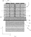
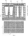
- Figure 1 schematically represents a centering system 1 for centering blanks outputted from a furnace 15 in a hot stamping line according to an example.
- Blanks may be transported by a conveyor system.
- a roller conveyor comprising a large number of conveyor rollers is shown.
- the conveyor rollers are distanced from each other in a conveying direction (x-axis in figure 1 ).
- the rollers may be driven by motors that can control the speed of the conveyor rollers.
- Conveyor rollers 14 convey the blanks through furnace 15.
- the blanks are heated to a desired temperature.
- a desired temperature may be around 900 °C.
- a door 12 is provided at the exit of the furnace. The door is configured or controlled to open when the blanks arrive and to close again when the blanks have left the furnace. This way the heat produced inside the furnace can be kept inside the furnace.
- the hot forming line is designed for four blanks being hot formed simultaneously.
- the hot forming line is designed for four blanks being hot formed simultaneously.
- four blanks may be conveyed side by side through the furnace and onto the centering table.
- Each of the stoppers 22 may be individually controllable and move in the conveying direction (along the x-axis). The position of the stoppers determines the end position of the blanks before centering takes place.
- the conveyor rollers 16 may be intermittently driven. As the blanks exit the furnace, these conveyor rollers 16 are rotated to convey the blanks until they reach the stoppers. Then the rollers may be stopped.
- the centering table 1 may be composed by four independent shifting units 20 having eight lifting bars 18. Each of the lifting bars is arranged in between two of the conveyor rollers 16. The lifting bars can thus move upwards (in the illustration of figure 1 , upward out of the paper; z-axis as indicated in figure 2 ) in between the conveyor rollers to lift the blanks out of the "pre-centering plane".
- the system may also comprise a plurality of centering pins 24 and pre-centering pins.
- a selection of the centering pins may be non-actuated pins and others may be actuated pins, which means respectively that they are either retracted with respect to the movement path of the blanks, and therefore they are not interacting with the blanks, or that they are non-retracted with respect to the movement path of the blanks, and therefore they are able to interact with the edges of the blanks (i.e. stop and/or centre the blanks).
- the selection of pins that are actuated and non-actuated may be adapted in accordance with the number of blanks, type of blanks and dimensions of blanks.
- a selection of the pins may be passive, i.e. they always maintain the same position, and the same height.
- a selection or all of the pins may be controlled to adapt their height.
- the pins may be underneath the plane of the conveying plane (i.e. the plane coinciding with the top of the conveyor rollers) as the blanks are conveyed towards the stoppers. Then, subsequently for centering the pins may be raised to reach a height at least above the conveying plane.
- a selection of the pins may be controlled to adapt their position in a horizontal direction perpendicular to the conveying direction, i.e. along the y-axis indicated in figure 1 .
- pre-centering may occur after the blanks have reached the stoppers. The position of the blanks along the x-axis is thereby determined. Then, in order to bring the blanks in the correct orientation, a number of (pre)-centering pins may be driven along the y-axis and slightly reposition of the blanks.
- each shifting unit 20 can move along the z-axis and raise the blanks. Then, the shifting units may be displaced along the y-axis against centering pins. The centering pins thereby determine the end positions of the blanks.
- the width of the centering table 1 is larger than the width of the furnace 15.
- the furnace may have a width of approximately 2,3 meters, whereas the width of the centering table 1 may be approximately 3 meters.
- the centering table according to this example makes it possible to increase the distance between the blanks in order for their further processing.
- the width of the furnace does not need to be increased accordingly, which can reduce the cost of the furnace as well as the energy consumption.
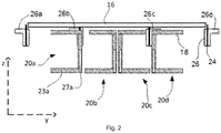
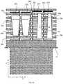
- Figure 2 schematically illustrates a cross-sectional side view of a centering system for centering blanks according to the example of figure 1 .
- the shifting units 20 and the lifting bars 18 are in a retracted position, below the conveying plane defined by the top surface of the conveyor rollers 16.
- pins 24 are as well retracted and thus, below the rollers 16 level.
- each of these shifting units may comprise base 23 and an actuator 27 to adapt the height of the lifting bars 18.
- the base 23a and actuator 27a are indicated for shifting unit 20a.
- the actuator shown may be e.g. a hydraulic or pneumatic or actuator.
- each of the lifting bars may have an individual actuator.
- pin bases 26a, 26b, 26c and 26d in which pins 24 are sunk (in the situation shown in figure 2 ).
- the pins may be driven out of their bases using suitable actuators (e.g. hydraulic, pneumatic or electric involving gears).
- the pin bases may be elongated guides along which the pins can slide. In the view of figure 1 , they may extend sideways and may be arranged in between the conveyor rollers. The bases and the lifting bars may be relatively thin so that they fit next to each other in between the conveyor rollers 16.
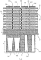
- Figures 3a - 3e schematically illustrate in top view a sequence of situations occurring during an example of a method for centering blanks.
- the centering system depicted in the sequence of figures 3a - 3e is generally very similar to the system of figures 1 and 2 .
- the same elements are indicated using the same reference signs.
- active centering pins are indicated with reference signs 24.
- Passive centering pins are indicated with reference signs 25.
- some of the pins which are herein shown to be active may then be passive and vice versa.
- FIG 3a four blanks are shown.
- a pair of blanks 10a and 10b is of a first type, whereas another pair of blanks 11a and 11b is of a different type.
- the blanks are shown to be in the furnace, whereas the door 12 of the furnace is closed.
- the conveyor rollers 14 are driven to convey the blank towards the exit and towards the centering table.
- conveyor rollers 16 are driven to forward the blanks in the x-direction ( figure 3c ).
- the conveyor rollers may be inactivated, so that when the stoppers 22a - 22d return to their original position, the blanks do not move.
- a pre-centering step may take place (not illustrated).
- a number of pre-centering pins may be moved along the y-direction to correctly orient the blanks.
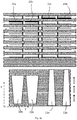
- FIG 3d the furnace door 12 is shown to be closed again and the stoppers 22a - 22d have moved partly towards their original position.
- the blanks may then be lifted out of the conveying plane using the lifting bars 18 that are raised along the z-axis.
- centering pins 24 are raised in the same direction. Some of the centering pins may have already been in a raised position. For example, centering pins 24a, 24b, 24g and 24h are relatively far removed from a normal conveying path of the blanks and there would be no need to withdraw them underneath the conveying plane.
- centering pins 24d, 24e and 24f may interfere with the movement of the blanks. These centering pins may thus be raised to their position for centering after the blanks have reached their respective stoppers.
- shifting units 22a and 22b with their corresponding lifting bars may be moved towards the left (in a "negative” direction along the y-axis), whereas the shifting units 22c and 22d may be moved towards the right (in a "positive” direction along the y-axis).
- this pin may be raised to its position used for centering only after the shifting units have started moving.
- Blank 10a is in contact with centering pins 24a and 24b.
- Blank 10b is in contact with centering pins 24c and 24d.
- Blank 11a is in contact with centering pins 24e and 24f.
- Blank 11b is in contact with centering pins 24g and 24h.
- the shifting units 20a and 20b as compared to previous figures have been moved along the y-axis in a negative direction.
- the shifting units 20c and 20d have moved along the y-axis in a position direction.
- the outer shifting units 20a and 20d may have moved more than the inner shifting units 20b and 20c.
- the shifting units will thus not interfere with each other Distance y2 is larger than distance y1.
- distance y4 may be larger than distance y3, or at least of substantially the same magnitude.
- the distance between the pairs of blanks has been increased.
- the distance between blanks 10a and 10b on the one hand, and the distance between blanks 11a and 11b may be increased.
- the outer positions of the blanks may thus be beyond the width of the furnace.
- the furnace may thus be narrower, whereas at the same time the blanks may have sufficient spacing in order to be able to be transferred to the hot press(es) correctly.
- each of the blanks may still be positioned in the same end position even if they exit the furnace in slightly different positions along the y-axis.
- a transfer robot (not shown), for example a suitable industrial robot, may pick up a blank 10 from the shifting unit and place it on the hot press (not shown).
- the transfer robot to this end may comprise a plurality of gripping units to grab and pick up the blanks.
- Gripping unit as used herein is to be understood as covering e.g. suction cups, clamps or similar.
- a single transfer robot may comprise several groups of gripping units, each group configured for picking up a blank, i.e. a single transfer robot can pick up more than one blanks at the same time.
- a plurality of transfer robots is provided, wherein each of the transfer robot is configured to pick up a single blank.
- industrial robot herein e.g. covers an automatically controlled, reprogrammable, and optionally multipurpose, manipulator programmable in three or more axes, which may be either fixed in place or mobile for use in industrial automation applications, as defined by the International Organization for Standardization in ISO 8373.
- the transfer robots may be (re) programmable, in accordance with their programming they will be able to pick up blanks only if they are positioned and centered correctly and consistently. This is what the centering table according to the examples and according to the methods disclosed herein ensures.
- each of the blanks may have an individual shifting unit and optionally an individual transfer robot for transferring the blanks from the centering table towards the hot press(es).
Landscapes
- Engineering & Computer Science (AREA)
- Mechanical Engineering (AREA)
- Physics & Mathematics (AREA)
- Thermal Sciences (AREA)
- Shaping Metal By Deep-Drawing, Or The Like (AREA)
- Press Drives And Press Lines (AREA)
- Blow-Moulding Or Thermoforming Of Plastics Or The Like (AREA)
Claims (15)
- Ein Zentrierungssystem (1) zur Zentrierung von Rohlinge (10a, 10b, 11a, 11b), die aus einem Ofen (15) in einer Heißprägungslinie ausgegeben werden, wobei das Zentrierungssystem (1) folgendes umfasst:eine Förderanlage zum Empfang von einer Vielzahl von Rohling (10a, 10b, 11a, 11b), die aus einem Ofen (15) ausgegeben werden und zur Verschiebung der Rohlinge (10a, 10b, 11a, 11b) mindestens entlang einer ersten horizontalen Achse;Verschiebeeinheiten (20) für jeden einzelnen Rohling (10a, 10b, 11a, 11b), wobei die Verschiebeeinheiten (20) zur Bewegung entlang einer zweiten im Wesentlichen senkrecht zur ersten Achse horizontalen Achse konfiguriert sind und jede Verschiebeeinheit (20) unabhängig entlang der zweiten Achse bewegbar ist;dadurch gekennzeichnet, dass:die Verschiebeeinheiten zwei oder mehr einstellbare Hebestangen (18) umfassen, und wobei die einstellbaren Hebestangen (18) konfiguriert sind, um die Rohlinge (10a, 10b, 11a, 11b) entlang einer im Wesentlichen senkrecht zu der ersten und der zweiten Achse vertikalen Achse zu heben; wobeidas Zentrierungssystem (1) weiterhin eine Vielzahl von Zentrierstiften (24) zur Zentrierung der Rohlinge (10a, 10b, 11a, 11b) umfasst, so dass die Rohlinge (10a, 10b, 11a, 11b) zentriert werden können, in dem die einzelnen Rohlinge (10a, 10b, 11a, 11b) entlang der zweiten Achse gegen die Zentrierstifte (24) bewogen werden.
- Ein Zentrierungssystem (1) nach Anspruch 1, wobei das Zentrierungssystem (1) weiterhin einen oder mehrere Anschläge (22) zum Stoppen der Rohlinge (10a, 10b, 11a, 11b) entlang der ersten Achse umfasst.
- Ein Zentrierungssystem (1) nach Anspruch 2, umfassend einen Anschlag (22) für jeden einzelnen Rohling (10a, 10b, 11a, 11b).
- Ein Zentrierungssystem (1) nach einem der Ansprüche 1 - 3, wobei die Förderanlage eine Rollenförderanlage ist, die eine Vielzahl von entlang der ersten Achse getrennten Förderwalzen (16) hat, wobei die Hebestangen (18) der Verschiebeeinheiten (20) zwischen den Förderwalzen (16) angeordnet sind.
- Ein Zentrierungssystem (1) nach einem der Ansprüche 1 - 4, wobei einer oder mehrere der Zentrierstifte (24, 25) entlang der zweiten Achse bewegbar sind.
- Ein Zentrierungssystem (1) nach einem der Ansprüche 1 - 5, wobei einer oder mehrere der Zentrierstifte (24) entlang der vertikalen Achse bewegbar sind.
- Ein Zentrierungssystem (1) nach einem der Ansprüche 1 - 6, weiterhin umfassend Vorzentrierstifte, die entlang der zweiten Achse zur Vorzentrierung der Rohlinge (10a, 10b, 11a, 11b) in einer durch die erste und die zweite Achse definierten Vorzentrierebene bewegbar sind.
- Ein Zentrierungssystem (1) nach einem der Ansprüche 1 - 7, wobei das Zentrierungssystem (1) vier Verschiebeeinheiten (20) umfasst.
- Ein Zentrierungssystem (1) nach Anspruch 8, wobei Paare der Verschiebeeinheiten (20) zur Bewegung von einer neutralen Position bis zu einer Zentrierungsposition in entgegengesetzten Richtungen konfiguriert sind.
- Ein Fördersystem einschließlich eines Zentrierungssystems (1) nach einem der Ansprüche 1 - 9, und eines oder mehrerer Übertragungsroboter zur Übertragung der einzelnen Rohlinge zu einer Warmformpresse.
- Ein Verfahren zur Zentrierung von Rohlingen in einer Heißprägungslinie durch Einsatz von einem Zentrierungssystem (1) nach einem der Ansprüche 1 - 9, wobei das Verfahren folgendes umfasst:empfangen von einer Vielzahl von Rohlingen (10a, 10b, 11a, 11b) aus einem Ofen (15) und Verschiebung der Vielzahl von Rohlingen (10a, 10b, 11a, 11b) mindestens entlang einer ersten horizontalen Achse;heben der Rohlinge (10a, 10b, 11a, 11b) aus einer durch die erste horizontale Achse und eine zweite zur ersten horizontalen Achse senkrechte horizontale Achse definierten Vorzentrierungsebene, entlang einer dritten zur Ebene senkrechten Achse;zentrieren der Rohlinge (10a, 10b, 11a, 11b), indem die einzelnen Rohlinge (10a, 10b, 11a, 11b) entlang der zweiten Achse gegen Zentrierstifte (24) bewogen werden.
- Ein Verfahren nach Anspruch 11, weiterhin umfassend das Vorzentrieren der Rohlinge in der Vorzentrierebene, bevor die Rohlinge (10a, 10b, 11a, 11b) gehoben werden.
- Ein Verfahren nach Anspruch 11 oder 12, wobei das Zentrieren der Rohlinge (10a, 10b, 11a, 11b) das Bewegen von mindestens zwei Rohlingen in entgegengesetzten Richtungen entlang der zweiten Achse umfasst.
- Ein Verfahren nach einem der Ansprüche 11 - 13, wobei das Zentrieren der Rohlinge (10a, 10b, 11a, 11b) das Bewegen von einem oder mehreren der Zentrierstifte (24) bis zu einer Zentrierposition umfasst, bevor die Rohlinge gegen die Zentrierstifte (24) bewogen werden.
- Ein Verfahren nach Anspruch 14, wobei die Zentrierpositionen der Zentrierstifte (24) verschiedene Höhen haben.
Priority Applications (5)
| Application Number | Priority Date | Filing Date | Title |
|---|---|---|---|
| ES15382493.3T ES2667769T3 (es) | 2015-10-13 | 2015-10-13 | Sistema de centrado para preformas |
| EP15382493.3A EP3156146B1 (de) | 2015-10-13 | 2015-10-13 | Zentrierungssystem für zuschnitten |
| US15/280,887 US10799929B2 (en) | 2015-10-13 | 2016-09-29 | Centering blanks |
| CN201610881027.5A CN106563738B (zh) | 2015-10-13 | 2016-10-09 | 定中心坯件 |
| US17/023,069 US11192164B2 (en) | 2015-10-13 | 2020-09-16 | Centering blanks |
Applications Claiming Priority (1)
| Application Number | Priority Date | Filing Date | Title |
|---|---|---|---|
| EP15382493.3A EP3156146B1 (de) | 2015-10-13 | 2015-10-13 | Zentrierungssystem für zuschnitten |
Publications (2)
| Publication Number | Publication Date |
|---|---|
| EP3156146A1 EP3156146A1 (de) | 2017-04-19 |
| EP3156146B1 true EP3156146B1 (de) | 2018-03-14 |
Family
ID=54337227
Family Applications (1)
| Application Number | Title | Priority Date | Filing Date |
|---|---|---|---|
| EP15382493.3A Active EP3156146B1 (de) | 2015-10-13 | 2015-10-13 | Zentrierungssystem für zuschnitten |
Country Status (4)
| Country | Link |
|---|---|
| US (2) | US10799929B2 (de) |
| EP (1) | EP3156146B1 (de) |
| CN (1) | CN106563738B (de) |
| ES (1) | ES2667769T3 (de) |
Families Citing this family (7)
| Publication number | Priority date | Publication date | Assignee | Title |
|---|---|---|---|---|
| JP2016205899A (ja) * | 2015-04-17 | 2016-12-08 | 株式会社ミツトヨ | 回転テーブルの制御方法及び装置 |
| EP3559283A1 (de) * | 2016-12-22 | 2019-10-30 | Autotech Engineering S.L. | Verfahren zum erwärmen eines rohlings und heizsystem |
| FR3082128B1 (fr) * | 2018-06-06 | 2022-01-21 | Psa Automobiles Sa | Dispositif de centrage de flans |
| CN109877239A (zh) * | 2019-03-15 | 2019-06-14 | 凌云吉恩斯科技有限公司 | 一种热成型产线自动匹配产品的伺服阻挡器 |
| DE102020103276A1 (de) * | 2020-02-10 | 2021-08-12 | Benteler Automobiltechnik Gmbh | Ofen zur partiellen Erwärmung von Metallbauteilen |
| US11318517B2 (en) * | 2020-09-30 | 2022-05-03 | Ford Global Technologies, Llc | System and method for heating metal blanks |
| DE102020129506A1 (de) * | 2020-11-09 | 2022-05-12 | Ebner Industrieofenbau Gmbh | Zentrierungsvorrichtung für Metallplatinen |
Citations (5)
| Publication number | Priority date | Publication date | Assignee | Title |
|---|---|---|---|---|
| US3344633A (en) | 1964-09-16 | 1967-10-03 | Walter W Wilson | Automatic bending brake |
| DE2534819A1 (de) | 1975-08-05 | 1977-02-24 | Schuler Gmbh L | Vorrichtung zum entstapeln und transportieren von platinen |
| DE3311116A1 (de) | 1983-03-26 | 1984-09-27 | SMS Schloemann-Siemag AG, 4000 Düsseldorf | Verfahren und vorrichtung zum ausrichten von blechen auf einem rollgang |
| JPS642741A (en) | 1987-06-25 | 1989-01-06 | Orii:Kk | Alignment of press working product |
| US20140144198A1 (en) | 2012-11-28 | 2014-05-29 | John Richard Potocki | Hot Stamping System And Method |
Family Cites Families (7)
| Publication number | Priority date | Publication date | Assignee | Title |
|---|---|---|---|---|
| DE19819965A1 (de) * | 1998-05-05 | 1999-11-11 | Schuler Pressen Gmbh & Co | Traversen-Dreiachstransfer |
| EP1990110A1 (de) * | 2007-05-08 | 2008-11-12 | Güdel Group Ag | Zentriervorrichtung für flächige Werkstücke in einer Presse und Verfahren zum Einrichten einer solchen Zentriervorrichtung |
| EP2734462B1 (de) * | 2011-07-21 | 2019-03-20 | ThyssenKrupp System Engineering GmbH | Vorrichtung und verfahren zum stoppen und/oder ausrichten von transportgütern auf einer fördereinrichtung und fördereinrichtung |
| CN203018628U (zh) | 2013-01-21 | 2013-06-26 | 长沙长泰机器人有限公司 | 一种基于视觉系统的机器人柔性冲压工件搬运系统 |
| CN103111536B (zh) | 2013-02-16 | 2015-02-04 | 王玉亮 | 热冲压成型生产线出炉板坯举升及水平方向定位装置 |
| CN103240350B (zh) | 2013-04-26 | 2015-08-12 | 长沙长泰机器人有限公司 | 一种高温板料输送定位台 |
| CN203470711U (zh) | 2013-09-02 | 2014-03-12 | 凌云工业股份有限公司 | 一种滚床对中系统 |
-
2015
- 2015-10-13 EP EP15382493.3A patent/EP3156146B1/de active Active
- 2015-10-13 ES ES15382493.3T patent/ES2667769T3/es active Active
-
2016
- 2016-09-29 US US15/280,887 patent/US10799929B2/en active Active
- 2016-10-09 CN CN201610881027.5A patent/CN106563738B/zh active Active
-
2020
- 2020-09-16 US US17/023,069 patent/US11192164B2/en active Active
Patent Citations (5)
| Publication number | Priority date | Publication date | Assignee | Title |
|---|---|---|---|---|
| US3344633A (en) | 1964-09-16 | 1967-10-03 | Walter W Wilson | Automatic bending brake |
| DE2534819A1 (de) | 1975-08-05 | 1977-02-24 | Schuler Gmbh L | Vorrichtung zum entstapeln und transportieren von platinen |
| DE3311116A1 (de) | 1983-03-26 | 1984-09-27 | SMS Schloemann-Siemag AG, 4000 Düsseldorf | Verfahren und vorrichtung zum ausrichten von blechen auf einem rollgang |
| JPS642741A (en) | 1987-06-25 | 1989-01-06 | Orii:Kk | Alignment of press working product |
| US20140144198A1 (en) | 2012-11-28 | 2014-05-29 | John Richard Potocki | Hot Stamping System And Method |
Non-Patent Citations (1)
| Title |
|---|
| SCHULER GROUP: "Hot Stamping Machines with PCH Flex Technology", 25 September 2015 (2015-09-25), XP054979001 |
Also Published As
| Publication number | Publication date |
|---|---|
| EP3156146A1 (de) | 2017-04-19 |
| ES2667769T3 (es) | 2018-05-14 |
| US20170100760A1 (en) | 2017-04-13 |
| US11192164B2 (en) | 2021-12-07 |
| CN106563738B (zh) | 2020-06-26 |
| US20200406328A1 (en) | 2020-12-31 |
| CN106563738A (zh) | 2017-04-19 |
| US10799929B2 (en) | 2020-10-13 |
Similar Documents
| Publication | Publication Date | Title |
|---|---|---|
| US11192164B2 (en) | Centering blanks | |
| JP6985683B2 (ja) | ロボットシステム、ロボットシステムの制御方法および処理システム | |
| EP2875878B1 (de) | Automatisches herstellungssystem für pressteile unter verwendung einer doppelroboterstrasse für eine tandempressenstrasse | |
| CN108349669B (zh) | 通用的自动化堆叠装置 | |
| US10954577B2 (en) | Hot-forming line for manufacturing hot-formed and press-hardened steel-sheet products, and method for operating said hot-forming line | |
| WO2017002404A1 (ja) | 焼結体の製造装置、及び焼結体の製造方法 | |
| CN108112241B (zh) | 辊锻机及辊锻方法 | |
| EP2991811B1 (de) | Bearbeitungszentrum | |
| CN114502295A (zh) | 用于运送和/或操纵部件的方法 | |
| KR100715422B1 (ko) | 다공정 프레스 시스템 | |
| US10058964B2 (en) | Transport device for transporting a work piece along consecutive processing stations of a production installation, a production installation, a multistage forming press, and a method for manufacturing products from work pieces by means of a production installation | |
| CN208179278U (zh) | 一种磨床上下料机械手 | |
| US9533337B2 (en) | Apparatus and method for producing at least partially closed hollow profiles with a short cycle time | |
| US10335848B2 (en) | Press-molded article manufacturing system and method for changing press molds and grippers | |
| CN206952068U (zh) | 一种步进梁精锻设备 | |
| US20220314298A1 (en) | Transfer method, manipulation system designed therefor, and bending installation | |
| CN214298045U (zh) | 粉末冶金自动排坯机 | |
| CN111225771A (zh) | 用于定向两个工件以用于构造接合连接的方法和操纵器 | |
| CN210435802U (zh) | 一种cnc自动上下料系统 | |
| RU2374024C2 (ru) | Способ ковки в штампах и кузнечное устройство для осуществления способа | |
| BG66732B1 (bg) | Автоматична линия за производство на детайли за изработване на стоманени врати | |
| BG1830U1 (bg) | Автоматична линия за производство на детайли за изработване на стоманени врати | |
| CN113458843A (zh) | 具有双入口和双出口的机床以及相关使用方法 | |
| KR101423931B1 (ko) | 싱글 또는 더블 로봇라인을 구비한 복수의 탠덤 프레스 라인에서 프레스 금형 및 그리퍼의 동시 교환방법 |
Legal Events
| Date | Code | Title | Description |
|---|---|---|---|
| PUAI | Public reference made under article 153(3) epc to a published international application that has entered the european phase |
Free format text: ORIGINAL CODE: 0009012 |
|
| STAA | Information on the status of an ep patent application or granted ep patent |
Free format text: STATUS: THE APPLICATION HAS BEEN PUBLISHED |
|
| AK | Designated contracting states |
Kind code of ref document: A1 Designated state(s): AL AT BE BG CH CY CZ DE DK EE ES FI FR GB GR HR HU IE IS IT LI LT LU LV MC MK MT NL NO PL PT RO RS SE SI SK SM TR |
|
| AX | Request for extension of the european patent |
Extension state: BA ME |
|
| STAA | Information on the status of an ep patent application or granted ep patent |
Free format text: STATUS: REQUEST FOR EXAMINATION WAS MADE |
|
| 17P | Request for examination filed |
Effective date: 20171019 |
|
| RBV | Designated contracting states (corrected) |
Designated state(s): AL AT BE BG CH CY CZ DE DK EE ES FI FR GB GR HR HU IE IS IT LI LT LU LV MC MK MT NL NO PL PT RO RS SE SI SK SM TR |
|
| GRAP | Despatch of communication of intention to grant a patent |
Free format text: ORIGINAL CODE: EPIDOSNIGR1 |
|
| STAA | Information on the status of an ep patent application or granted ep patent |
Free format text: STATUS: GRANT OF PATENT IS INTENDED |
|
| INTG | Intention to grant announced |
Effective date: 20171220 |
|
| GRAS | Grant fee paid |
Free format text: ORIGINAL CODE: EPIDOSNIGR3 |
|
| GRAA | (expected) grant |
Free format text: ORIGINAL CODE: 0009210 |
|
| STAA | Information on the status of an ep patent application or granted ep patent |
Free format text: STATUS: THE PATENT HAS BEEN GRANTED |
|
| AK | Designated contracting states |
Kind code of ref document: B1 Designated state(s): AL AT BE BG CH CY CZ DE DK EE ES FI FR GB GR HR HU IE IS IT LI LT LU LV MC MK MT NL NO PL PT RO RS SE SI SK SM TR |
|
| REG | Reference to a national code |
Ref country code: GB Ref legal event code: FG4D |
|
| REG | Reference to a national code |
Ref country code: CH Ref legal event code: EP Ref country code: AT Ref legal event code: REF Ref document number: 978355 Country of ref document: AT Kind code of ref document: T Effective date: 20180315 |
|
| REG | Reference to a national code |
Ref country code: IE Ref legal event code: FG4D |
|
| REG | Reference to a national code |
Ref country code: DE Ref legal event code: R096 Ref document number: 602015008759 Country of ref document: DE |
|
| REG | Reference to a national code |
Ref country code: ES Ref legal event code: FG2A Ref document number: 2667769 Country of ref document: ES Kind code of ref document: T3 Effective date: 20180514 |
|
| REG | Reference to a national code |
Ref country code: NL Ref legal event code: MP Effective date: 20180314 |
|
| REG | Reference to a national code |
Ref country code: LT Ref legal event code: MG4D |
|
| PG25 | Lapsed in a contracting state [announced via postgrant information from national office to epo] |
Ref country code: LT Free format text: LAPSE BECAUSE OF FAILURE TO SUBMIT A TRANSLATION OF THE DESCRIPTION OR TO PAY THE FEE WITHIN THE PRESCRIBED TIME-LIMIT Effective date: 20180314 Ref country code: CY Free format text: LAPSE BECAUSE OF FAILURE TO SUBMIT A TRANSLATION OF THE DESCRIPTION OR TO PAY THE FEE WITHIN THE PRESCRIBED TIME-LIMIT Effective date: 20180314 Ref country code: HR Free format text: LAPSE BECAUSE OF FAILURE TO SUBMIT A TRANSLATION OF THE DESCRIPTION OR TO PAY THE FEE WITHIN THE PRESCRIBED TIME-LIMIT Effective date: 20180314 Ref country code: FI Free format text: LAPSE BECAUSE OF FAILURE TO SUBMIT A TRANSLATION OF THE DESCRIPTION OR TO PAY THE FEE WITHIN THE PRESCRIBED TIME-LIMIT Effective date: 20180314 Ref country code: NO Free format text: LAPSE BECAUSE OF FAILURE TO SUBMIT A TRANSLATION OF THE DESCRIPTION OR TO PAY THE FEE WITHIN THE PRESCRIBED TIME-LIMIT Effective date: 20180614 |
|
| REG | Reference to a national code |
Ref country code: AT Ref legal event code: MK05 Ref document number: 978355 Country of ref document: AT Kind code of ref document: T Effective date: 20180314 |
|
| PG25 | Lapsed in a contracting state [announced via postgrant information from national office to epo] |
Ref country code: RS Free format text: LAPSE BECAUSE OF FAILURE TO SUBMIT A TRANSLATION OF THE DESCRIPTION OR TO PAY THE FEE WITHIN THE PRESCRIBED TIME-LIMIT Effective date: 20180314 Ref country code: BG Free format text: LAPSE BECAUSE OF FAILURE TO SUBMIT A TRANSLATION OF THE DESCRIPTION OR TO PAY THE FEE WITHIN THE PRESCRIBED TIME-LIMIT Effective date: 20180614 Ref country code: GR Free format text: LAPSE BECAUSE OF FAILURE TO SUBMIT A TRANSLATION OF THE DESCRIPTION OR TO PAY THE FEE WITHIN THE PRESCRIBED TIME-LIMIT Effective date: 20180615 Ref country code: LV Free format text: LAPSE BECAUSE OF FAILURE TO SUBMIT A TRANSLATION OF THE DESCRIPTION OR TO PAY THE FEE WITHIN THE PRESCRIBED TIME-LIMIT Effective date: 20180314 Ref country code: SE Free format text: LAPSE BECAUSE OF FAILURE TO SUBMIT A TRANSLATION OF THE DESCRIPTION OR TO PAY THE FEE WITHIN THE PRESCRIBED TIME-LIMIT Effective date: 20180314 |
|
| REG | Reference to a national code |
Ref country code: FR Ref legal event code: PLFP Year of fee payment: 4 |
|
| PG25 | Lapsed in a contracting state [announced via postgrant information from national office to epo] |
Ref country code: RO Free format text: LAPSE BECAUSE OF FAILURE TO SUBMIT A TRANSLATION OF THE DESCRIPTION OR TO PAY THE FEE WITHIN THE PRESCRIBED TIME-LIMIT Effective date: 20180314 Ref country code: PL Free format text: LAPSE BECAUSE OF FAILURE TO SUBMIT A TRANSLATION OF THE DESCRIPTION OR TO PAY THE FEE WITHIN THE PRESCRIBED TIME-LIMIT Effective date: 20180314 Ref country code: AL Free format text: LAPSE BECAUSE OF FAILURE TO SUBMIT A TRANSLATION OF THE DESCRIPTION OR TO PAY THE FEE WITHIN THE PRESCRIBED TIME-LIMIT Effective date: 20180314 Ref country code: NL Free format text: LAPSE BECAUSE OF FAILURE TO SUBMIT A TRANSLATION OF THE DESCRIPTION OR TO PAY THE FEE WITHIN THE PRESCRIBED TIME-LIMIT Effective date: 20180314 Ref country code: EE Free format text: LAPSE BECAUSE OF FAILURE TO SUBMIT A TRANSLATION OF THE DESCRIPTION OR TO PAY THE FEE WITHIN THE PRESCRIBED TIME-LIMIT Effective date: 20180314 Ref country code: IT Free format text: LAPSE BECAUSE OF FAILURE TO SUBMIT A TRANSLATION OF THE DESCRIPTION OR TO PAY THE FEE WITHIN THE PRESCRIBED TIME-LIMIT Effective date: 20180314 |
|
| PG25 | Lapsed in a contracting state [announced via postgrant information from national office to epo] |
Ref country code: SM Free format text: LAPSE BECAUSE OF FAILURE TO SUBMIT A TRANSLATION OF THE DESCRIPTION OR TO PAY THE FEE WITHIN THE PRESCRIBED TIME-LIMIT Effective date: 20180314 Ref country code: AT Free format text: LAPSE BECAUSE OF FAILURE TO SUBMIT A TRANSLATION OF THE DESCRIPTION OR TO PAY THE FEE WITHIN THE PRESCRIBED TIME-LIMIT Effective date: 20180314 Ref country code: SK Free format text: LAPSE BECAUSE OF FAILURE TO SUBMIT A TRANSLATION OF THE DESCRIPTION OR TO PAY THE FEE WITHIN THE PRESCRIBED TIME-LIMIT Effective date: 20180314 Ref country code: CZ Free format text: LAPSE BECAUSE OF FAILURE TO SUBMIT A TRANSLATION OF THE DESCRIPTION OR TO PAY THE FEE WITHIN THE PRESCRIBED TIME-LIMIT Effective date: 20180314 |
|
| REG | Reference to a national code |
Ref country code: DE Ref legal event code: R026 Ref document number: 602015008759 Country of ref document: DE |
|
| PLBI | Opposition filed |
Free format text: ORIGINAL CODE: 0009260 |
|
| PG25 | Lapsed in a contracting state [announced via postgrant information from national office to epo] |
Ref country code: PT Free format text: LAPSE BECAUSE OF FAILURE TO SUBMIT A TRANSLATION OF THE DESCRIPTION OR TO PAY THE FEE WITHIN THE PRESCRIBED TIME-LIMIT Effective date: 20180716 |
|
| PLAX | Notice of opposition and request to file observation + time limit sent |
Free format text: ORIGINAL CODE: EPIDOSNOBS2 |
|
| 26 | Opposition filed |
Opponent name: BENTELER AUTOMOBILTECHNIK GMBH Effective date: 20181214 |
|
| PG25 | Lapsed in a contracting state [announced via postgrant information from national office to epo] |
Ref country code: DK Free format text: LAPSE BECAUSE OF FAILURE TO SUBMIT A TRANSLATION OF THE DESCRIPTION OR TO PAY THE FEE WITHIN THE PRESCRIBED TIME-LIMIT Effective date: 20180314 |
|
| PLBB | Reply of patent proprietor to notice(s) of opposition received |
Free format text: ORIGINAL CODE: EPIDOSNOBS3 |
|
| REG | Reference to a national code |
Ref country code: CH Ref legal event code: PL |
|
| RAP2 | Party data changed (patent owner data changed or rights of a patent transferred) |
Owner name: AUTOTECH ENGINEERING S.L. |
|
| REG | Reference to a national code |
Ref country code: BE Ref legal event code: MM Effective date: 20181031 |
|
| PG25 | Lapsed in a contracting state [announced via postgrant information from national office to epo] |
Ref country code: MC Free format text: LAPSE BECAUSE OF FAILURE TO SUBMIT A TRANSLATION OF THE DESCRIPTION OR TO PAY THE FEE WITHIN THE PRESCRIBED TIME-LIMIT Effective date: 20180314 Ref country code: LU Free format text: LAPSE BECAUSE OF NON-PAYMENT OF DUE FEES Effective date: 20181013 |
|
| REG | Reference to a national code |
Ref country code: IE Ref legal event code: MM4A |
|
| PG25 | Lapsed in a contracting state [announced via postgrant information from national office to epo] |
Ref country code: LI Free format text: LAPSE BECAUSE OF NON-PAYMENT OF DUE FEES Effective date: 20181031 Ref country code: BE Free format text: LAPSE BECAUSE OF NON-PAYMENT OF DUE FEES Effective date: 20181031 Ref country code: CH Free format text: LAPSE BECAUSE OF NON-PAYMENT OF DUE FEES Effective date: 20181031 |
|
| PG25 | Lapsed in a contracting state [announced via postgrant information from national office to epo] |
Ref country code: IE Free format text: LAPSE BECAUSE OF NON-PAYMENT OF DUE FEES Effective date: 20181013 |
|
| PG25 | Lapsed in a contracting state [announced via postgrant information from national office to epo] |
Ref country code: MT Free format text: LAPSE BECAUSE OF NON-PAYMENT OF DUE FEES Effective date: 20181013 |
|
| PLCK | Communication despatched that opposition was rejected |
Free format text: ORIGINAL CODE: EPIDOSNREJ1 |
|
| PG25 | Lapsed in a contracting state [announced via postgrant information from national office to epo] |
Ref country code: TR Free format text: LAPSE BECAUSE OF FAILURE TO SUBMIT A TRANSLATION OF THE DESCRIPTION OR TO PAY THE FEE WITHIN THE PRESCRIBED TIME-LIMIT Effective date: 20180314 |
|
| APBM | Appeal reference recorded |
Free format text: ORIGINAL CODE: EPIDOSNREFNO |
|
| APBP | Date of receipt of notice of appeal recorded |
Free format text: ORIGINAL CODE: EPIDOSNNOA2O |
|
| APAH | Appeal reference modified |
Free format text: ORIGINAL CODE: EPIDOSCREFNO |
|
| PG25 | Lapsed in a contracting state [announced via postgrant information from national office to epo] |
Ref country code: MK Free format text: LAPSE BECAUSE OF NON-PAYMENT OF DUE FEES Effective date: 20180314 Ref country code: HU Free format text: LAPSE BECAUSE OF FAILURE TO SUBMIT A TRANSLATION OF THE DESCRIPTION OR TO PAY THE FEE WITHIN THE PRESCRIBED TIME-LIMIT; INVALID AB INITIO Effective date: 20151013 |
|
| APBQ | Date of receipt of statement of grounds of appeal recorded |
Free format text: ORIGINAL CODE: EPIDOSNNOA3O |
|
| PG25 | Lapsed in a contracting state [announced via postgrant information from national office to epo] |
Ref country code: IS Free format text: LAPSE BECAUSE OF FAILURE TO SUBMIT A TRANSLATION OF THE DESCRIPTION OR TO PAY THE FEE WITHIN THE PRESCRIBED TIME-LIMIT Effective date: 20180714 |
|
| PG25 | Lapsed in a contracting state [announced via postgrant information from national office to epo] |
Ref country code: SI Free format text: LAPSE BECAUSE OF NON-PAYMENT OF DUE FEES Effective date: 20181013 |
|
| PGFP | Annual fee paid to national office [announced via postgrant information from national office to epo] |
Ref country code: FR Payment date: 20221025 Year of fee payment: 8 |
|
| REG | Reference to a national code |
Ref country code: DE Ref legal event code: R100 Ref document number: 602015008759 Country of ref document: DE |
|
| APBU | Appeal procedure closed |
Free format text: ORIGINAL CODE: EPIDOSNNOA9O |
|
| PLBN | Opposition rejected |
Free format text: ORIGINAL CODE: 0009273 |
|
| STAA | Information on the status of an ep patent application or granted ep patent |
Free format text: STATUS: OPPOSITION REJECTED |
|
| 27O | Opposition rejected |
Effective date: 20230310 |
|
| PGFP | Annual fee paid to national office [announced via postgrant information from national office to epo] |
Ref country code: GB Payment date: 20231027 Year of fee payment: 9 |
|
| PGFP | Annual fee paid to national office [announced via postgrant information from national office to epo] |
Ref country code: ES Payment date: 20231102 Year of fee payment: 9 |
|
| PGFP | Annual fee paid to national office [announced via postgrant information from national office to epo] |
Ref country code: DE Payment date: 20231027 Year of fee payment: 9 |
|
| PG25 | Lapsed in a contracting state [announced via postgrant information from national office to epo] |
Ref country code: FR Free format text: LAPSE BECAUSE OF NON-PAYMENT OF DUE FEES Effective date: 20231031 |