EP3154434B1 - Systems and methods of automated dose control in x-ray imaging - Google Patents
Systems and methods of automated dose control in x-ray imaging Download PDFInfo
- Publication number
- EP3154434B1 EP3154434B1 EP15766932.6A EP15766932A EP3154434B1 EP 3154434 B1 EP3154434 B1 EP 3154434B1 EP 15766932 A EP15766932 A EP 15766932A EP 3154434 B1 EP3154434 B1 EP 3154434B1
- Authority
- EP
- European Patent Office
- Prior art keywords
- image
- ray
- exposure parameter
- computer processor
- projection images
- Prior art date
- Legal status (The legal status is an assumption and is not a legal conclusion. Google has not performed a legal analysis and makes no representation as to the accuracy of the status listed.)
- Active
Links
Images


Classifications
-
- A—HUMAN NECESSITIES
- A61—MEDICAL OR VETERINARY SCIENCE; HYGIENE
- A61B—DIAGNOSIS; SURGERY; IDENTIFICATION
- A61B6/00—Apparatus or devices for radiation diagnosis; Apparatus or devices for radiation diagnosis combined with radiation therapy equipment
- A61B6/02—Arrangements for diagnosis sequentially in different planes; Stereoscopic radiation diagnosis
- A61B6/03—Computed tomography [CT]
- A61B6/032—Transmission computed tomography [CT]
-
- A—HUMAN NECESSITIES
- A61—MEDICAL OR VETERINARY SCIENCE; HYGIENE
- A61B—DIAGNOSIS; SURGERY; IDENTIFICATION
- A61B6/00—Apparatus or devices for radiation diagnosis; Apparatus or devices for radiation diagnosis combined with radiation therapy equipment
- A61B6/40—Arrangements for generating radiation specially adapted for radiation diagnosis
- A61B6/4064—Arrangements for generating radiation specially adapted for radiation diagnosis specially adapted for producing a particular type of beam
- A61B6/4085—Cone-beams
-
- A—HUMAN NECESSITIES
- A61—MEDICAL OR VETERINARY SCIENCE; HYGIENE
- A61B—DIAGNOSIS; SURGERY; IDENTIFICATION
- A61B6/00—Apparatus or devices for radiation diagnosis; Apparatus or devices for radiation diagnosis combined with radiation therapy equipment
- A61B6/46—Arrangements for interfacing with the operator or the patient
- A61B6/461—Displaying means of special interest
- A61B6/466—Displaying means of special interest adapted to display 3D data
-
- A—HUMAN NECESSITIES
- A61—MEDICAL OR VETERINARY SCIENCE; HYGIENE
- A61B—DIAGNOSIS; SURGERY; IDENTIFICATION
- A61B6/00—Apparatus or devices for radiation diagnosis; Apparatus or devices for radiation diagnosis combined with radiation therapy equipment
- A61B6/48—Diagnostic techniques
- A61B6/488—Diagnostic techniques involving pre-scan acquisition
-
- A—HUMAN NECESSITIES
- A61—MEDICAL OR VETERINARY SCIENCE; HYGIENE
- A61B—DIAGNOSIS; SURGERY; IDENTIFICATION
- A61B6/00—Apparatus or devices for radiation diagnosis; Apparatus or devices for radiation diagnosis combined with radiation therapy equipment
- A61B6/50—Apparatus or devices for radiation diagnosis; Apparatus or devices for radiation diagnosis combined with radiation therapy equipment specially adapted for specific body parts; specially adapted for specific clinical applications
- A61B6/51—Apparatus or devices for radiation diagnosis; Apparatus or devices for radiation diagnosis combined with radiation therapy equipment specially adapted for specific body parts; specially adapted for specific clinical applications for dentistry
-
- A—HUMAN NECESSITIES
- A61—MEDICAL OR VETERINARY SCIENCE; HYGIENE
- A61B—DIAGNOSIS; SURGERY; IDENTIFICATION
- A61B6/00—Apparatus or devices for radiation diagnosis; Apparatus or devices for radiation diagnosis combined with radiation therapy equipment
- A61B6/52—Devices using data or image processing specially adapted for radiation diagnosis
- A61B6/5205—Devices using data or image processing specially adapted for radiation diagnosis involving processing of raw data to produce diagnostic data
-
- A—HUMAN NECESSITIES
- A61—MEDICAL OR VETERINARY SCIENCE; HYGIENE
- A61B—DIAGNOSIS; SURGERY; IDENTIFICATION
- A61B6/00—Apparatus or devices for radiation diagnosis; Apparatus or devices for radiation diagnosis combined with radiation therapy equipment
- A61B6/52—Devices using data or image processing specially adapted for radiation diagnosis
- A61B6/5211—Devices using data or image processing specially adapted for radiation diagnosis involving processing of medical diagnostic data
-
- A—HUMAN NECESSITIES
- A61—MEDICAL OR VETERINARY SCIENCE; HYGIENE
- A61B—DIAGNOSIS; SURGERY; IDENTIFICATION
- A61B6/00—Apparatus or devices for radiation diagnosis; Apparatus or devices for radiation diagnosis combined with radiation therapy equipment
- A61B6/52—Devices using data or image processing specially adapted for radiation diagnosis
- A61B6/5258—Devices using data or image processing specially adapted for radiation diagnosis involving detection or reduction of artifacts or noise
-
- A—HUMAN NECESSITIES
- A61—MEDICAL OR VETERINARY SCIENCE; HYGIENE
- A61B—DIAGNOSIS; SURGERY; IDENTIFICATION
- A61B6/00—Apparatus or devices for radiation diagnosis; Apparatus or devices for radiation diagnosis combined with radiation therapy equipment
- A61B6/54—Control of apparatus or devices for radiation diagnosis
- A61B6/542—Control of apparatus or devices for radiation diagnosis involving control of exposure
-
- G—PHYSICS
- G06—COMPUTING OR CALCULATING; COUNTING
- G06T—IMAGE DATA PROCESSING OR GENERATION, IN GENERAL
- G06T5/00—Image enhancement or restoration
-
- G—PHYSICS
- G16—INFORMATION AND COMMUNICATION TECHNOLOGY [ICT] SPECIALLY ADAPTED FOR SPECIFIC APPLICATION FIELDS
- G16H—HEALTHCARE INFORMATICS, i.e. INFORMATION AND COMMUNICATION TECHNOLOGY [ICT] SPECIALLY ADAPTED FOR THE HANDLING OR PROCESSING OF MEDICAL OR HEALTHCARE DATA
- G16H50/00—ICT specially adapted for medical diagnosis, medical simulation or medical data mining; ICT specially adapted for detecting, monitoring or modelling epidemics or pandemics
- G16H50/20—ICT specially adapted for medical diagnosis, medical simulation or medical data mining; ICT specially adapted for detecting, monitoring or modelling epidemics or pandemics for computer-aided diagnosis, e.g. based on medical expert systems
-
- A—HUMAN NECESSITIES
- A61—MEDICAL OR VETERINARY SCIENCE; HYGIENE
- A61B—DIAGNOSIS; SURGERY; IDENTIFICATION
- A61B6/00—Apparatus or devices for radiation diagnosis; Apparatus or devices for radiation diagnosis combined with radiation therapy equipment
- A61B6/08—Auxiliary means for directing the radiation beam to a particular spot, e.g. using light beams
-
- A—HUMAN NECESSITIES
- A61—MEDICAL OR VETERINARY SCIENCE; HYGIENE
- A61B—DIAGNOSIS; SURGERY; IDENTIFICATION
- A61B6/00—Apparatus or devices for radiation diagnosis; Apparatus or devices for radiation diagnosis combined with radiation therapy equipment
- A61B6/44—Constructional features of apparatus for radiation diagnosis
- A61B6/4429—Constructional features of apparatus for radiation diagnosis related to the mounting of source units and detector units
- A61B6/4435—Constructional features of apparatus for radiation diagnosis related to the mounting of source units and detector units the source unit and the detector unit being coupled by a rigid structure
- A61B6/4441—Constructional features of apparatus for radiation diagnosis related to the mounting of source units and detector units the source unit and the detector unit being coupled by a rigid structure the rigid structure being a C-arm or U-arm
-
- A—HUMAN NECESSITIES
- A61—MEDICAL OR VETERINARY SCIENCE; HYGIENE
- A61B—DIAGNOSIS; SURGERY; IDENTIFICATION
- A61B6/00—Apparatus or devices for radiation diagnosis; Apparatus or devices for radiation diagnosis combined with radiation therapy equipment
- A61B6/46—Arrangements for interfacing with the operator or the patient
- A61B6/461—Displaying means of special interest
- A61B6/463—Displaying means of special interest characterised by displaying multiple images or images and diagnostic data on one display
-
- A—HUMAN NECESSITIES
- A61—MEDICAL OR VETERINARY SCIENCE; HYGIENE
- A61B—DIAGNOSIS; SURGERY; IDENTIFICATION
- A61B6/00—Apparatus or devices for radiation diagnosis; Apparatus or devices for radiation diagnosis combined with radiation therapy equipment
- A61B6/46—Arrangements for interfacing with the operator or the patient
- A61B6/461—Displaying means of special interest
- A61B6/465—Displaying means of special interest adapted to display user selection data, e.g. graphical user interface, icons or menus
-
- A—HUMAN NECESSITIES
- A61—MEDICAL OR VETERINARY SCIENCE; HYGIENE
- A61B—DIAGNOSIS; SURGERY; IDENTIFICATION
- A61B6/00—Apparatus or devices for radiation diagnosis; Apparatus or devices for radiation diagnosis combined with radiation therapy equipment
- A61B6/46—Arrangements for interfacing with the operator or the patient
- A61B6/467—Arrangements for interfacing with the operator or the patient characterised by special input means
- A61B6/469—Arrangements for interfacing with the operator or the patient characterised by special input means for selecting a region of interest [ROI]
-
- A—HUMAN NECESSITIES
- A61—MEDICAL OR VETERINARY SCIENCE; HYGIENE
- A61B—DIAGNOSIS; SURGERY; IDENTIFICATION
- A61B6/00—Apparatus or devices for radiation diagnosis; Apparatus or devices for radiation diagnosis combined with radiation therapy equipment
- A61B6/54—Control of apparatus or devices for radiation diagnosis
- A61B6/542—Control of apparatus or devices for radiation diagnosis involving control of exposure
- A61B6/544—Control of apparatus or devices for radiation diagnosis involving control of exposure dependent on patient size
Definitions
- the present disclosure relates to X-ray imaging systems and methods.
- PCT Patent Application Publication No. WO2009156943 discloses an imaging generation device with optimized dose control that includes a noise determination unit for determining a distribution of noise in a projection domain of a region of interest and a dose control unit for determining a dose profile for a radiation source of the imaging generation device based on a determined distribution of noise by using a noise propagation algorithm.
- U.S. Patent Application No. 13/409,912 discloses a method to reduce radiation dose delivered by an imaging system.
- a virtual mask representation is selected based on a shape of an organ to be masked.
- the virtual mask representation is displayed on a scout image.
- a radiation dose to be delivered is manipulated so as to modify the virtual mask representation to obtain an optimum attenuation profile.
- PCT Application Publication No. WO2013049818 discloses a method of consistent and verifiable optimization of computed tomography (CT) radiation dose.
- CT computed tomography
- Mathematical models allow for estimation of patient size, image, size-specific radiation dose, and image quality targets based on digital image data and radiologist preferences.
- An automated system processes the image and dose data according to the mathematical models and stores and displays the information, enabling verification and ongoing monitoring of consistent dose optimization.
- An optimization model calculates specific scanner settings needed to attain target image quality at the minimum radiation dose possible.
- U.S. Patent No. 7,082,183 discloses computed tomography dose indexing phantom selection for dose reporting.
- a control mechanism in communication with an X-ray source and detector assembly includes logic that is adapted to execute at least one scout scan of the object to produce a first scout scan image.
- An elliptical patient model is generated based on the first scout scan image.
- the elliptical patient model is matched to a phantom diameter approximation.
- a dose report is generated based on the phantom diameter approximation. The dose report is displayed.
- 2007/0076842 represents the closest prior art and discloses a method of dose control in three-dimensional X-ray imaging and the corresponding X-ray imaging system, the method comprising: acquiring at least one image of an object with an X-ray emitter and an X-ray receiver; determining with at least one computer processor at least one physical characteristic of the object from the at least one image; determining with the at least one computer processor at least one exposure parameter value based upon the at least one physical characteristic of the object; acquiring with the X-ray emitter and X-ray receiver a plurality of projection images of the object using the at least one exposure parameter value; and reconstructing with the at least one computer processor a three-dimensional X-ray image from the plurality of projection images.
- the invention is defined by independent claims 1 and 12. Embodiments of the present disclosure not falling under the scope of the independent claims do not form part of the invention.
- the present disclosure results from the present inventors' research and development of improved X-ray imaging systems and methods.
- the inventors have realized that prior art X-ray systems and methods, including the systems and methods described herein above, often are not user friendly and can be inefficient and ineffective.
- the inventors have recognized that it is desirable to provide improved X-ray systems and methods that automatedly determine imaging exposure parameters.
- an operator may input a designated quality and exposure parameters are determined therefrom.
- the X-ray system and methods determine physical characteristics of the object and field of view to be imaged and exposure parameter are determined therefrom.
- the inventors have also recognized that it is desirable to provide improved X-ray systems and methods that limit excessive radiation to a patient being imaged.
- the inventors have realized that X-ray system operators may image patients at exposure parameters that produce X-ray images of a higher quality (e.g. less noise), resulting in greater exposure, than is necessary for intended purposes of the images. This can result in wasting time and applying excessive radiation to the patient.
- the present disclosure provides X-ray systems and methods that overcome disadvantages in the prior art.
- An exemplary embodiment of a method of exposure control in three-dimensional X-ray imaging includes acquiring at least one scout image with an X-ray emitter and an X-ray receiver.
- a computer processor determines at least one physical characteristic of the object to be imaged from the at least one scout image.
- the computer processor determines at least one exposure parameter value based upon the determined at least one physical characteristic of the object to be imaged.
- the X-ray emitter and X-ray receiver acquire a plurality of projection images about the object to be imaged using the at least one imaging parameter value.
- the computer processor reconstructs a three-dimensional X-ray image from the plurality of projection images.
- a method of exposure control in three-dimensional X-ray imaging includes acquiring at least one scout image with an X-ray emitter and an X-ray receiver.
- the X-ray emitter operates at an initial imaging parameter value.
- a computer processor determines at least one physical characteristic of the object to be imaged from the at least one scout image.
- a user input of image quality is received.
- the computer processor determines a new imaging parameter value based upon the determined at least one physical characteristic of the object to be imaged and the user input of image quality.
- the X-ray emitter and X-ray receiver acquire a plurality of projection images about the object to be imaged using the X-ray emitter operating at the new imaging parameter value.
- the computer processor reconstructs a three-dimensional X-ray image from the captured plurality of projection images.
- An exemplary embodiment of an X-ray imaging system includes an X-ray emitter configured to produce X-rays relative to an imaging parameter value and direct the X-rays towards an object to be imaged.
- An X-ray receiver is configured to receive X-rays from the X-ray emitter.
- the X-ray emitter and X-ray receiver are configured to acquire at least one scout image of the object to be imaged.
- An input device is configured to receive a user input of image quality.
- a computer processor is communicatively connected to the X-ray emitter, X-ray receiver, and the input device.
- the computer processor is configured to determine a physical characteristic of the object to be imaged from the at least one scout image.
- the computer processor is configured to determine a new imaging parameter value from the physical characteristic and the user input of image quality.
- the X-ray emitter and X-ray receiver are configured to acquire a plurality of projection images about the object to be imaged using the new imaging parameter value.
- the computer processor is configured to reconstruct a three-dimensional X-ray image from the captured plurality of projection images.
- Embodiments of the systems and methods as disclosed herein operate to automatically calculate exposure parameter values for use in a 3D imaging procedure of a patient.
- embodiments can determine optimal exposure parameter values which may include, but are not limited to kilovolts (kV) and milliamps (mA) provided to the X-ray emitter.
- kV kilovolts
- mA milliamps
- Embodiments may achieve this by determining physical characteristics of the patient, for example head size and/or density. Physical characteristics of size and/or density affect the total attenuation of X-rays by the object to be imaged.
- optimal noise filtering may also be automatedly determined.
- Some embodiments acquire scout images for patient positioning and field of view (FOV) identification purposes, and those scout images can also be used as inputs for automated determination of imaging parameter values. Thus, it may not be necessary to acquire additional scout images for the determination of the exposure parameters.
- FOV field of view
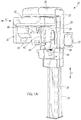
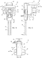
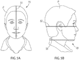
- Figures 1A-1D depict an exemplary X-ray imaging apparatus 20 for acquiring X-ray images of an object, including for example a dental or medical patient P (see e.g., FIGS. 5A and 5B ).
- the imaging apparatus 20 is configured for 3-D imaging of the dento-maxillofacial complex of the human skull; however other configurations of apparatuses for imaging of other portions of the object can instead be employed with the concepts of the present disclosure.
- the X-ray imaging apparatus 20 can optionally be configured to conduct different types of imaging procedures, for example panoramic imaging (for example standard, pediatric, ortho zone, wide arch, orthogonal, and/or the like), cephalometric imaging (for example cephalo pediatric lateral projection, cephalo lateral projection, cephalo postero-anterior, and/or the like).
- the X-ray imaging apparatus 20 is used for 3D imaging, exemplarily cone beam computed tomography (CBCT) 3D imaging.
- CBCT cone beam computed tomography
- the exemplary imaging apparatus 20 has a housing 22 that is movably supported on a support column 24.
- the housing 22 can be moved up and down in the vertical direction V via a conventional guide motor (not shown) that is configured to move the housing 22 vertically up and down along a track 26 extending along support column 24.
- the housing 22 includes a generally vertically extending guide section 28 disposed on the support column 24 and a generally horizontally extending support section 30 extending generally horizontally from the guide section 28.
- the support section 30 supports a rotating section 32 (sometimes referred to as a "gantry"), which is rotatable in a horizontal plane H with respect to the stationary support section 30, as shown at arrow 34 in Figure 1D .
- gantry rotating section 32
- the support section 30 and/or rotating section 32 contain a conventional guide motor (not shown) configured to rotate the rotating section 32, as shown at arrow 34.
- the apparatus can be mounted to a support structure including for example a wall instead of or in addition to being supported by a column.
- the emitter housing 36 contains an emitter generally located at 40 and supported in the emitter housing 36 and positioned to emit X-rays through the object being imaged (e.g. the patient P) to a receiver located at 42 and supported in the X-ray receiver housing 38.
- the emitter comprises an X-ray with a cathode and an anode.
- a power source (not depicted) produces a voltage, exemplarily in kilovolts (kV) across the cathode and anode to accelerate electrons from the cathode to the anode (not depicted).
- a current exemplarily in milliamps (mA) between tha cathode and the anode generally determines the amount of electrons emitted from the cathode.
- the anode comprises a target, which may exemplarily be made of tungsten that is generally angled so that electrons from the cathode striking the target will produce X-rays generally in the direction out of the emitter towards the receiver.
- a patient positioning housing 44 extends from the guide section 28 and includes a chin support 48 for positioning the head of the patient P between the opposed emitter 40 and receiver 42.
- a head support 46 extends from the support section 30 through the rotating section 32.
- the chin support 48 and head support 46 are optional and other means for positioning the patient can be employed.
- a patient positioning panel 68 is located on the patient positioning housing 44 and receives user inputs for adjusting the position of various components of the imaging apparatus 20, as will be discussed further herein below.
- a control panel 50 is attached to the housing 22 and is configured to receive user inputs for controlling the imaging apparatus 20 and to provide a display of functionalities of the imaging apparatus 20, as will be described further herein below.
- the control panel 50 can be supported by an arm 49 that pivots about the imaging apparatus 20 for positioning in the positions shown in Figures 1A and 1B-D , respectively.
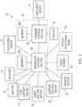
- FIG. 2 schematically depicts portions of an exemplary embodiment of an X-ray imaging system 52 that incorporates the X-ray imaging apparatus 20.
- the system 52 includes, among other things, a control circuit 59 that includes an apparatus control section 54 and a command control section 56.
- the control circuit 59 is one or more computer processors.
- the one or more computer processors may include integrated memory or be communicatively connected to memory upon which computer readable code is stored, the execution of the code by the one or more computer processors cause the computer processors to carry out the functions as disclosed herein.
- the apparatus control section 54 and command control section 56 each include a memory 58a, 58b, respectively.
- both the apparatus control section 54 and command control section 56 are programmable and can send and receive computer commands via wired or wireless links, including for example the links shown in solid-line format in Figure 2 .
- the command control section 56 can send electronic signals/commands to the apparatus control section 54 and can receive electronic signals/commands from the apparatus control section 54.
- the apparatus control section 54 can send computer electronic signals/commands to the command control section 56 and can receive electronic signals/commands from the command control section 56.
- the example shown in Figure 2 depicts two control sections 54, 56 that function together, alternative arrangements could include only one control section or more than two control sections that function together by sending and/or receiving commands to and from each other, respectively.
- Control sections 54, 56 may be software modules operating on a single computer processor, or may be separate computer processors respectively executing command and/or apparatus control computer readable code.
- the examples described in the present disclosure are not limited to the specific system 52 arrangements and configurations depicted in Figure 2 .
- the apparatus control section 54 is collocated with the X-ray imaging apparatus 20 and controls various functionalities of the X-ray imaging apparatus 20.
- the apparatus control section 54 communicates via electronic signals/commands with the memory 58a; with a guide section motor 60 for causing movement of the guide section 28 along the support column 24; with a support section motor 62 for causing rotational movement of the rotating section 32; with a chin support motor 61 for causing movement of the chin support 48; and with the touch screen display 50 for displaying apparatus characteristics and functionalities and for receiving user inputs, as will be discussed further herein below.
- a head support motor (not shown) can also be included for causing movement of the head support 46.
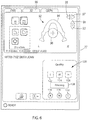
- the apparatus control section 54 can receive commands from a user input device 74, including for example the imaging button 66 shown in Figures 2 and 7 and from the patient positioning panel 68 shown in Figure 4 . Operation of the user input device 74 and the patient positioning panel 68 will be described further herein below.
- the apparatus control section 54 also sends and receives electronic signals/commands with the emitter 40 and receiver 42 to control the emitter 40 and receiver 42 and obtain imaging data that can be converted into X-ray image(s) of the object being imaged (e.g., patient P).
- the apparatus control section 54 receives patient positioning inputs from the patient positioning panel 68 and sends corresponding command signals to the guide section motor 60, support section motor 62, and chin support motor 61 to position the apparatus 20 with respect to the patient P.
- the system 20 can include more or fewer motors and movable sections than what is shown and described and in some examples can provide complete three-dimensional movement of the apparatus 20 with respect to the patient P.
- the apparatus control section 54 can receive patient positioning inputs from the patient positioning panel 68 and send corresponding command signals to move the patient P with respect to the apparatus 20, via for example a chair that is movable by a conventional chair guide motor (not shown).
- the apparatus control section 54 can control the relative positioning of both the apparatus 20 and a chair guide motor to achieve a user-desired position.
- the apparatus control section 54 can also be configured to control positioning lights 70 (see e.g. Figures 2 , 5A and 5B ) for identifying on the object being imaged a field of view that is desired for imaging, as will be described further herein below.
- the patient and/or apparatus 20 may be positioned manually relative to one another.
- the apparatus control section 54 is also configured to communicate with the command control section 56, to receive electronic signals/commands from the command control section 56, and to provide image data received from the receiver 42 to the command control section 56.
- an exemplary command control section 56 can be a personal computer 72 having a user input device 74, which in the example shown is a keyboard, and having a display 76, which in the example shown is a computer monitor.
- a user input device 74 which in the example shown is a keyboard
- a display 76 which in the example shown is a computer monitor.
- the display 76 and input device 74 can instead or also comprise a touch screen device, a mouse, a handheld computer device and/or the like.
- a patient P is initially positioned in the apparatus 20 between the emitter 40 and receiver 42.
- the patient P is positioned with the chin on the chin support 48 and with the head on the head support 46.
- the patient positioning panel 68 is manually operated to instruct the apparatus control section 54 to control the apparatus 20 and position the apparatus 20 into a position that is generally appropriate for X-ray imaging of the patient P. This can be done by for example the guide section motor 60, chin support motor 61, and /or support section motor 62, as described above.
- pressing input key 86 turns on the positioning lights 70 as shown in Figures 5A and 5B , to assist in the aforementioned positioning of the patient P.
- Figures 5A and 5B depict exemplary positioning lights 70, including a midsagittal light 51 and horizontal top and bottom lights 53, 55, respectively, delineating a desired field of view for the X-ray process. Additional patient positioning lights 70 can be employed. Use of positioning lights 70 is optional and other configurations for positioning than that shown may be used.
- Pressing input key 88 on the patient positioning panel 68 signals the apparatus control section 54 that positioning instructions are going to be input by the user and causes the apparatus to rotate into a position for further patient positioning.
- Pressing arrows 78, 80 on the patient positioning panel 68 instructs the apparatus control section 54 to move the apparatus 20 up and down, respectively.
- the user can thus watch the positioning lights 70 and use the arrows 78, 80 and 82, 84 to position the lights 70 (and thus the apparatus) into an appropriate position on the patient P.
- Pressing input keys 78, 80 instructs the apparatus control section 54 to control the respective support section motor 62 to move the apparatus 20.
- Pressing arrows 82, 84 instructs the apparatus control section 54 to control the chin support motor 61 to move the chin support 48 up and down, respectively.
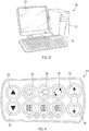
- the command control section 56 controls the display 76 to visually present a graphical user interface (GUI) 77 that includes a presentation of an initial view 92 of the object, representing in this example the anatomy of the patient P to be imaged.
- GUI graphical user interface
- the GUI 77 that includes the initial view 92 can also or instead be displayed on the touch screen display 50, as controlled by the apparatus control section 54, or on another graphical display device, for example a handheld device, television screen and/or the like.
- the initial view 92 includes a generic model 94 of a patient's jaw.
- the initial view 92 can include a picture or an X-ray image of the object, for example a particular anatomy of the patient P.
- an initial X-ray can be taken with the X-ray imaging apparatus 20 to generate the initial view 92 for viewing by the user.
- a position marker 96 is shown in the GUI 77.
- the position marker 96 illustrated in Figure 6 has a circular shape and crosshairs; however, other configurations of the position marker may be utilized.
- the position marker 96 indicates a particular 3-D volume that is desired for imaging. In an embodiment, the position marker 96 indicates a center of a volume to be imaged.
- the position marker 96 overlaps the initial view 92 and is movable in the GUI 77 with respect to the initial view 92.
- the position marker 96 can also be resized to convey the volume of the region to be imaged.
- the initial view 92 can be movable with respect to the position marker 96.
- both the initial view 92 and position marker 96 can be movable with respect to each other. Relative movement of the initial view 92 and position marker 96, as described above, can be requested via the input device 74 and/or via positioning keys on a touch screen configuration, for example touch screen display 50, including for example up and down arrows 91, 93 and left and right arrows 95, 97.
- a touch screen configuration for example touch screen display 50, including for example up and down arrows 91, 93 and left and right arrows 95, 97.
- Other configurations for modifying the presentation of the initial view 92 in the GUI 77 can be utilized, for example by voice commands, a mouse pad, drag-and-drop touch screen commands, and/or the like.
- Input keys are also provided on the GUI 77 for selecting between panoramic, 3-D, and cephalometric imaging modalities.
- the present example relates to 3-D imaging, which can be selected at input key 99; however the principles disclosed herein could be applied in other imaging modalities, as described herein above.
- the GUI 77 can thus be modified by the user to identify a specific area of interest on the initial view 92 of which the user desires a 3-D image.
- the user modifies the GUI 77 by moving the position marker 96 to the area of interest on the initial view 92 and in an additional embodiment, may adjust the size of the position marker 96 to encompass a desired volume to be imaged.
- the user may then operate the input device 64 by pressing imaging button 66, which instructs the apparatus control section 54 to control the imaging apparatus 20, including for example the guide section 28, support section 30 and rotating section 32 to move into a position with respect to the patient P that is commensurate with the position marker 96 on the initial view 92.
- the apparatus 20 is thus positioned wherein the emitter 40 and receiver 42 operate to obtain one or more scout images of the patient P that correspond to the relative positioning of the position marker 96 and initial view 92 on the GUI 77.
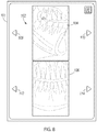
- control circuit 59 is programmed to operate the emitter and receiver in accordance with the user modifications to the initial view at 92 in order to acquire at least one scout image of the patient, which is exemplarily depicted at Figure 8.
- Figure 8 depicts a graphical display 101 that presents scout images that may be taken in accordance with the user inputs described above.
- one or more scout images may be acquired and used for patient positioning.
- the scout images 102 include a first scout image 104 and a second scout image 106, although a person of ordinary skill in the art will recognize that in alternative embodiments more or fewer scout images may be acquired.
- scout images may be limited to a portion of the patient dento-maxillofacial area, in other embodiments a larger portion of the patient, including, but not limited to the entire head of a patient may be imaged in the scout images.
- the scout images 102 are exemplarily taken of the patient from different angles, which in the example shown are an orthogonal view 104 and a tangential view 106.
- Some exemplary embodiments as disclosed herein use the at least one scout image, already acquired for patient positioning purposes as described herein, to further automatedly determine at least one exposure parameter value.
- the at least one scout image may be used only for processing purposes and not presented to the user.
- the X-ray imaging system may be operated to provide automatic dose control (ADC).
- ADC automatic dose control
- the systems and methods of ADC as described in further detail herein provide the functionality and benefit of automatedly determining at least one exposure parameter value for use in 3D X-ray imaging from the at least one scout image.
- X-ray dose to the patient may be optimized while relying on less technical user input.
- the user selects the automated dose control feature or mode of operation by selecting the "A" button 118 while the initial view is presented in the GUI 77.
- the imaging system may also operate in a manual mode (by selection of the "M" button 130) or in a test mode (by selection office "T" button 132).
- a manual mode the exposure settings are manually selected.
- a test mode a specific predetermined combination of exposure settings is selected.
- the GUI 120 may change to present an interface configured to receive inputs specifically directed to the selected mode of operation.
- the user inputs a desired image quality by selecting a low button 122, a medium button 124, or a high button 126 in order to select between low, medium, and high quality images to be acquired.
- desired image quality is representative of the noise found in the acquired X-ray projection images or alternatively, a signal to noise ratio of the acquired X-ray projection images.
- the user inputs a desired quality/noise level for the resulting 3D image reconstruction.
- the noise in the X-ray projection images is a function of the physical characteristics of the object/patient to be imaged (e.g. size, density, or attenuation) and the exposure parameters used to operate the X-ray imaging apparatus (e.g. mA, kV, exposure time, duty cycle, number of projection images, voxel size, and the reconstruction system and/or software).
- a user may also be prompted to input whether image noise reduction software filtration is to be used in the 3D reconstruction process, exemplarily by selecting or not selecting a "filtering" button 128.
- a user may provide an input representative of an amount of filtering, exemplarily high, medium, or low filtering is to be used.
- image noise reduction software filtration results in images that have the same noise level or quality to those taken with greater X-ray exposure, but possibly at the cost of reduced resolution. Therefore, the addition of image noise reduction software filtration, or the use of higher filtration can result in achieving suitable image quality with reduced X-ray exposure to the patient. It will be recognized that depending upon the purpose of the imaging, the user may select an appropriate level of quality and/or resolution/filtering only as is needed to achieve the purpose of the images to be taken.
- automated dose control can be carried out dependent upon image quality and be based upon "mA compensation.”
- mA compensation may be where the system increases a strength of the projection image filtration when a user reduces emitter current (mA).
- mA emitter current
- Such an embodiment may find application with adult patients when an operator evaluates that less emitter current is enough for a particular task (e.g. willing to accept the resulting compromise with image quality).
- a filtration is automatedly selected so that the image noise level keeps constant or is partially compensated with other emitter current values or reduces an increase in noise resulting from the lowered emitter current.
- Figures 9-11 are flow charts that depict exemplary embodiments of methods of automatic dose control in an X-ray imaging apparatus.
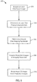
- Figure 9 depicts an exemplary embodiment of a method 200 of automatic exposure control in an X-ray imaging apparatus.
- the method 200 begins at 202 when at least one scout image is acquired.
- the acquisition of at least one scout image may occur after a generalized area for imaging or an initial view has been selected.
- the at least one scout image may be a previously acquired image, including, but not limited to, a CBCT image, panoramic, or cephalometric image of the patient.
- scout images may be acquired after a patient has been properly positioned in the X-ray imaging apparatus as described above, and the user exemplarily selects 3D X-ray imaging and a field of view (FOV) size on the X-ray imaging apparatus.
- FOV field of view
- the at least one scout image can be any image capable of being used as described herein, including, but not limited to at least one projection image acquired for the purpose of patient positioning, at least one image acquired for the specific purpose of automatic dose control, or at least one image acquired during the course of an imaging procedure.
- the systems and methods as disclosed herein may use any of a variety of images as scout images independent of the purpose for which the image was initially obtained, provided that the image is suitable for automatic dose control purposes.
- the at least one scout image(s) is acquired at default values for the exposure parameters identified above, so long as the values of the exposure of parameters used are known and can be used as disclosed in further detail herein.
- the acquired scout images may be used to position the patient and/or select a refined FOV for the 3D imaging.
- At 204 at least one physical characteristic of the object to be imaged, or a portion of the object to be imaged, is determined based on one or more characteristics of the at least one scout image (for example, without limitation, brightness, contrast, noise level, and/or visible anatomical features) and one or more of the exposure parameters used to take the scout image(s).
- characteristics of the at least one scout image for example, without limitation, brightness, contrast, noise level, and/or visible anatomical features
- the determination is of a level of noise in the image which may be caused by the at least one physical characteristic of the object.
- the physical characteristic determined at 204 is at least one of a size, density, or attenuation of the object to be imaged. It will be recognized that a head of a child patient will usually be smaller, less dense, and exhibit less attenuation in the at least one scout image as compared to at least one scout image of the head of an adult patient, when the at least one scout images are acquired at the same exposure parameter values. As noted above, if the exposure parameter values used to obtain the at least one scout images are known, the size, density, or attenuation of the objected imaged in the scout images can be determined at 204.
- the exposure parameters may include a variety of parameters, including, but not limited to emitter voltage, emitter current, a number of projection images, a voxel size, a reconstruction system or software, an exposure time, and/or a duty cycle. Values for one or more of these exposure parameters can be determined at least in part from the determined physical characteristic from 204.
- the emitter voltage, number of projection images, and voxel size may be fixed or predefined with values for use in association with the ADC operation. With these exposure parameters predetermined, both patient dose and X-ray image quality (as defined by a noise level) are functions of the emitter current (mA) at 206.
- a value of emitter current may be therefore determined at least in part based on the physical characteristics determined at 204.
- a larger, denser object to be imaged will result in more attenuation which requires greater emitter current to achieve the purpose of the X-ray images. Therefore, increased size, density, or attenuation of the object to be imaged results in an increased value for the at least one exposure parameter.
- the least one exposure parameter value determined at 206 is used to acquire a plurality of projection images.
- the plurality of projection images are exemplarily acquired at the exposure parameter value by rotating the X-ray emitter and receiver incrementally about the head of the patient while capturing a series of X-ray projection images at these rotated intervals while operating the emitter or other portions of the X-ray imaging system at the exposure parameter value.
- a 3D image is reconstructed from the acquired plurality of projection images.
- the reconstruction of the 3D image may be achieved using a variety of reconstruction techniques.
- an iterative reconstruction technique for example algebraic reconstruction technique (ART) that beings with an initial reconstruction and iteratively refines the reconstruction based upon additional information from the projection images, may be used.
- a non-iterative reconstruction technique for example, filtered back projection (FBP), may be used.
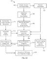
- Figure 10 is a flowchart of an additional exemplary embodiment of a method 300 of automatic dose control in an X-ray imaging apparatus. More specifically, the exemplary embodiment of the method 300 depicts one embodiment in which a user is prompted for or provides user inputs that are used to further refine the automatic dose control features.
- the method 300 begins with the acquisition of at least one scout image at 302. After the at least one scout image is acquired at 302, some optional embodiments may receive a selection of a field of view (FOV) as described above with respect to Figs. 6 and 8 .
- FOV field of view
- at 304 at least one physical characteristic value is determined by analyzing the at least one scout image, and in particular, the selected field of view in the at least one scout image.
- the at least one physical characteristic can be determined from the scout images to include a value for an object size, density or attenuation and this determination of a physical characteristic value at 304 may be facilitated in embodiments wherein the at least one scout image is acquired at default or known exposure parameter values which can then be used to exemplarily determine an amount of attenuation experienced in the at least one scout image.
- separate scout images are used for patient positioning and for ADC calculations.
- additional scout images or scout images from one or more particular angles may be needed for the attenuation calculations as disclosed in further detail herein.
- the required number of scout images from the at least one scout image may depend upon the specific application of physical structure or structures being imaged. In an embodiment, a sufficient number of scout images are analyzed such that the scout images cover the full object to be imaged and a reliable estimate of the object attenuation can be made.
- the determined physical characteristic may be an average noise level (e.g. pixel standard deviation value) or an average density (e.g. pixel mean value).
- the determination of physical characteristics at 304 is facilitated if at least one scout image is acquired at known or referenced exposure parameter values.
- the at least one scout image is acquired at a reference emitter current that is selected to result in a known noise level in the reconstructed volume of a known reference object size.
- a determined lower emitter current as explained in further detail herein would result in a nosier reconstruction image and a higher emitter current would result in a reconstructed image with less noise.
- the determination of exposure parameters as described in further detail herein in embodiments is dependent upon establishing connection between the reconstructed image quality (e.g. noise level) and the at least one physical characteristic determined at 304 from the scout image, which may include a noise level of the scout image.
- the emitter current used to acquire the at least one scout image is constant across scout images between different patients, then the size, density, and attenuation of the object to be imaged is a considerable factor in a quality of later acquired projection images and reconstructed 3D image.
- the more exposure parameter values held constant across the plurality of scout images including emitter current, emitter voltage, field of view size, and image resolution, make the determinations of physical characteristics more straight forward and therefore would require less calibration and/or compensation, in order to make the determinations of physical characteristics.
- a user input of desired image quality is received.
- one potential benefit of certain embodiments as disclosed herein is to decrease user dependence upon technical knowledge and experience in order to select proper imaging exposure parameter values. Therefore, in one embodiment, and as depicted in the user interface of Figure 6 , the user inputs a selection of a desired low, medium, or high quality 3D reconstruction, depending upon the purposes for which the 3D reconstruction is being used, and/or the image quality needs.
- image quality may represent, fully or partially, an acceptable level of noise in the plurality of projection images or the resulting 3D reconstruction.
- the user input of desired quality at 306 can comprise a selection of high, medium, or low level of noise, or a specific signal to noise ratio that is acceptable to the user.
- At 308 at least one exposure parameter value is determined.
- the at least one exposure parameter value may be determined at 308 in a variety of ways.
- the exposure parameter value may be determined based upon a determined physical characteristic of total attenuation determined at 304 and the field of view size in order to generate either a projection image or a reconstruction 3D image with a predetermined acceptable noise level.
- the user input/selection of desired quality is used to define the acceptable noise level. This embodiment provides the user with additional control over the automatically determined at least one exposure parameter value.
- the at least one exposure parameter value is emitter current.
- at 310 a user input of desired resolution is received.
- the noise level in the reconstructed image can also be affected by the use of noise reduction software filtration.
- the noise reduction software filtration "softens" or blurs the reconstructed image thus reducing resolution by averaging across pixel values.
- noise reduction software filtration enables achievement of a same level of noise with reduced emitter current and patient dose, albeit typically with reduced resolution. Therefore, if, by inputting a desired resolution at 310, the user indicates that a reduced resolution is acceptable, then the emitter current and overall patient dose may be reduced further than would have been determined from the physical characteristics and desired image quality alone.
- the user input of desired resolution may be a user selection of a high resolution, normal resolution, or low resolution. Since the resolution in the context of these embodiments can be affected by noise-reduction software filtration, in an additional embodiment, the user input of desired resolution may be an indication of whether or not to use noise reduction software filtering, as shown exemplarily in the user input controls of Figure 6 . In still further embodiments, a user input of a low, medium, or high level of software filtering may also be received.
- suitable noise filtering is determined.
- low, medium, and high degrees of noise reduction software filtering may be available, and one or more of these options may be selected by the user.
- the measured total attenuation as determined at 304 may be used to automatically determine the suitable noise filtering.
- the reconstruction image will be blurred more by stronger projection image noise reduction software filtering than by a lower level of noise reduction software filtering. The stronger noise filtering will also have the most impact in reducing noise level. Therefore, in most cases, the lower total attenuation (e.g.
- Fig. 12 depicts a merely exemplary embodiment of a portion of a graphical user interface 150 configured to receive a user input selection of an image quality.
- the GUI 150 is an additional embodiment to the desired image quality GUI 120 described above with respect to Fig. 6 .
- an exemplary five options are presented to the user in "effective" terms rather than "technical” terms of actual imaging parameter values. These options include “Minimum Noise, High Detail” 152, “Reduced Dose, High Detail” 154, "Standard Image Quality” 156, "Minimum Noise, Reduced Detail” 158, and “Reduced Dose, Reduced Detail” 160.
- the five options presented above represent a descending order of dose and an increasing order of image filtration, as explained above.
- Options 152 and 154 offer lower noise filtration, resulting in the "High Detail” indication, while options 158 and 160 offer increased noise filtration indicated by “Reduced Detail.”
- options 152 and 158 use higher emitter currents (“Minimum Noise”) than options 154 and 160, respectively ("Reduced Dose”).
- the "Standard Image Quality” option 156 represents a balance between dose and detail.
- an embodiment wherein noise reduction software filtering is used in the system can employ reduced emitter current, thus resulting in a lower patient dose. Therefore, the use and strength of noise reduction software filtering can further be used in embodiments at 308 to determine the at least one exposure parameter value.
- the exposure parameter value may be presented at 312, exemplarily on a graphical display, and further exemplarily in GUI 77, as the actual numerical values that are determined at 308 and thereafter used by the imaging apparatus.
- the exposure parameter value may be indicated to the user on relative terms. In a non-limiting example, if the exposure parameter is emitter current, the user may be presented with information indicating whether a low, medium, or high emitter current has been determined for use in the acquisition of the projection images.
- the determined at least one exposure parameter value and a determined noise reduction software filtering are presented to the user for confirmation.
- the imaging apparatus is operated to acquire a plurality of projection images using the determined at least one exposure parameter.
- the at least one exposure parameter is an emitter current and the imaging apparatus operates the emitter with the determined value for the emitter current in order to obtain the plurality of projection images.
- the determined noise filter is used to filter the projection images.
- filtering of the projection images averages or smooths pixel values across an acquired image, typically reducing resolution but improving noise level.
- a 3D image is reconstructed from the plurality of projection images.
- a variety of 3D image reconstruction techniques are available and may be used in exemplary embodiments of the method 300.
- a rough estimation may be made about the gray values of the target volume.
- the gray values may be estimated by back-projection the scout images before the actual acquisition of the projection images.
- the scout images may first be down-sampled (and/or averaged) before the scout images are back-projected.
- the scout images and/or the back-projected images may be processed (e.g. down-sampled and/or averaged).
- secondary estimations such as minimum, maximum, difference, mean, or median estimations of gray values can be calculated from the back-projected scout images.
- the secondary estimations of gray values are used at 308 to determine at least one imaging parameter (e.g. emitter current (mA), number of images, or KVS) and/or image processing parameters (e.g. pre-processing filter, MAR) that are used for the actual acquisition of the projection images.
- at least one imaging parameter e.g. emitter current (mA), number of images, or KVS
- image processing parameters e.g. pre-processing filter, MAR
- these estimations of gray values from 322 can be used as the determined physical characteristics, or as an independent value used in the determination of at least one imaging parameter at 308.
- Figure 11 is a flow chart of an exemplary embodiment of a method 400 of automatic dose control in an X-ray imaging apparatus.
- the method 400 discloses an exemplary embodiment of a method wherein the scout images are acquired in the course of an imaging procedure to capture a plurality of projection images.
- the scout images can be projection images acquired during an imaging procedure which may be used in a 3-D reconstruction.
- the method of automatic dose control can be performed during an imaging procedure in some non-limiting embodiments, the method of automatic dose control may be performed at other times in an imaging procedure apart from, or in addition to any automatic dose control performed at the start of an imaging procedure.
- a user input of desired image quality is received at 402.
- This user input of desired image quality may exemplarily be received through the GUI as described about with respect to Figure 6 , and as described in further detail with respect to Figure 10 .
- some embodiments of the method 400 may further receive a user input of desired resolution as described above with respect to Figure 10 .
- a 3D imaging procedure is initiated at 406.
- the 3D imaging procedure includes the acquisition of a plurality of projection images.
- the plurality of projection images are acquired in two portions.
- the imaging apparatus acquires at least one scout image as a first portion of the plurality of projection images.
- the at least one scout image is acquired at an angle relative to the object to be imaged (e.g. patient's head) that is suitable for representing the physical characteristics of the object to be imaged.
- the object to be imaged e.g. patient's head
- two or more scout images are acquired and in a further embodiment, at least two of the acquired scout images are generally orthogonal to one another.
- the at least one scout image acquired as the first portion of the plurality of projection images is analyzed at 410 to determine at least one physical characteristic of the object to be imaged.
- the at least one physical characteristic may be a size, density and/or attenuation of the object to be imaged.
- the determination of the at least one physical characteristic at 410 is facilitated by the at least one scout image being acquired at 408 at known exposure parameter values and may be further facilitated by calibration of the known exposure parameter values, for example, by comparing the actual scout image(s) to expected image results from an object with known physical characteristics. These calibrations and relationships may be experimentally determined or modeled and stored at the computer processor, or memory communicatively connected to the computer processor.
- At least one exposure parameter value can be determined at 412.
- the at least one exposure parameter value may be determined solely from the at least one physical characteristic, or in combination with additional information, which in embodiments may include the user input of desired image quality received at 402.
- additional information which in embodiments may include the user input of desired image quality received at 402.
- a level of noise filtering that will achieve the user input of desired resolution is determined. As detailed above, if noise filtering is used, this may further enable the reduction of patient dose and therefore at 412 may result in the determination of an exposure parameter value that is less than if no noise filtering were used.
- the control circuit After the at least one exposure parameter value is determined at 412, the control circuit operates the imaging apparatus to adjust at least one exposure parameter to the values determined at 412. After adjusting the at least one exposure parameter value at 416, the imaging apparatus operates at 418 to acquire a second portion of the plurality of projection images.
- the second portion of the plurality of projection images completes the acquisition of the plurality of projection images to be used in the 3D reconstruction.
- the first portion of the plurality of projection images may, optionally, be a relatively small number
- the second portion of the plurality of projection images acquired with the adjusted at least one exposure parameter value may, in exemplary embodiments, be 100 or more projection images.
- the plurality of projection images are filtered at 420 in order to improve the noise level in the projection images and improve the noise level in the resulting 3D reconstruction.
- a 3D image is created at 422 from the plurality of projection images exemplarily by known reconstruction techniques.
- the present disclosure thus provides examples of X-ray imaging systems that comprise an imaging apparatus having emitter emitting X-rays through an object and a receiver receiving the X-rays, and a control circuit controlling the emitter and processing the X-rays received by the receiver to generate X-ray images of the object.
- Specific examples of the imaging apparatus and control circuit are described with reference to the attached drawing Figures. These examples are not limiting, and the concepts of the present disclosure are applicable to other types of imaging apparatus having different configurations of control circuitry.
- the control circuit determines at least one exposure parameter value. In some embodiments, this is achieved through user selection of desired quality and physical characteristics based on analysis of at least one scout image. In an additional exemplary embodiment, this may be performed during an imaging procedure.
- ADC automatic dose control
Landscapes
- Health & Medical Sciences (AREA)
- Life Sciences & Earth Sciences (AREA)
- Engineering & Computer Science (AREA)
- Medical Informatics (AREA)
- Public Health (AREA)
- Biomedical Technology (AREA)
- Pathology (AREA)
- General Health & Medical Sciences (AREA)
- Physics & Mathematics (AREA)
- Surgery (AREA)
- Radiology & Medical Imaging (AREA)
- Optics & Photonics (AREA)
- Heart & Thoracic Surgery (AREA)
- Molecular Biology (AREA)
- Nuclear Medicine, Radiotherapy & Molecular Imaging (AREA)
- Animal Behavior & Ethology (AREA)
- High Energy & Nuclear Physics (AREA)
- Biophysics (AREA)
- Veterinary Medicine (AREA)
- Computer Vision & Pattern Recognition (AREA)
- Theoretical Computer Science (AREA)
- Human Computer Interaction (AREA)
- Pulmonology (AREA)
- Dentistry (AREA)
- Oral & Maxillofacial Surgery (AREA)
- Data Mining & Analysis (AREA)
- Databases & Information Systems (AREA)
- Epidemiology (AREA)
- Primary Health Care (AREA)
- General Physics & Mathematics (AREA)
- Apparatus For Radiation Diagnosis (AREA)
Priority Applications (2)
| Application Number | Priority Date | Filing Date | Title |
|---|---|---|---|
| EP20215026.4A EP3811871B1 (en) | 2014-06-13 | 2015-05-27 | Systems and methods of automated dose control in x-ray imaging |
| DK20215026.4T DK3811871T3 (da) | 2014-06-13 | 2015-05-27 | System og fremgangsmåde til automatiseret doseringsstyring ved røntgen¬afbildning |
Applications Claiming Priority (2)
| Application Number | Priority Date | Filing Date | Title |
|---|---|---|---|
| US14/304,378 US10278666B2 (en) | 2014-06-13 | 2014-06-13 | Systems and methods of automated dose control in x-ray imaging |
| PCT/IB2015/001261 WO2015189694A1 (en) | 2014-06-13 | 2015-05-27 | Systems and methods of automated dose control in x-ray imaging |
Related Child Applications (1)
| Application Number | Title | Priority Date | Filing Date |
|---|---|---|---|
| EP20215026.4A Division EP3811871B1 (en) | 2014-06-13 | 2015-05-27 | Systems and methods of automated dose control in x-ray imaging |
Publications (2)
| Publication Number | Publication Date |
|---|---|
| EP3154434A1 EP3154434A1 (en) | 2017-04-19 |
| EP3154434B1 true EP3154434B1 (en) | 2020-12-23 |
Family
ID=54150465
Family Applications (2)
| Application Number | Title | Priority Date | Filing Date |
|---|---|---|---|
| EP15766932.6A Active EP3154434B1 (en) | 2014-06-13 | 2015-05-27 | Systems and methods of automated dose control in x-ray imaging |
| EP20215026.4A Active EP3811871B1 (en) | 2014-06-13 | 2015-05-27 | Systems and methods of automated dose control in x-ray imaging |
Family Applications After (1)
| Application Number | Title | Priority Date | Filing Date |
|---|---|---|---|
| EP20215026.4A Active EP3811871B1 (en) | 2014-06-13 | 2015-05-27 | Systems and methods of automated dose control in x-ray imaging |
Country Status (7)
Families Citing this family (21)
| Publication number | Priority date | Publication date | Assignee | Title |
|---|---|---|---|---|
| US9968307B2 (en) * | 2012-12-24 | 2018-05-15 | General Electric Company | Systems and methods for selecting parameters using contrast and noise |
| WO2016011489A1 (en) * | 2014-07-23 | 2016-01-28 | The University Of Sydney | Thoracic imaging for cone beam computed tomography |
| US10973479B2 (en) * | 2016-05-16 | 2021-04-13 | Canon Medical Systems Corporation | X-ray diagnosis apparatus, X-ray diagnosis apparatus controlling method, and X-ray diagnosis system |
| JP6938322B2 (ja) * | 2016-10-14 | 2021-09-22 | 株式会社モリタ製作所 | 医療用x線撮影装置の操作パネル表示装置、医療用x線撮影装置、医療用x線撮影装置の操作パネル表示装置における表示方法及び表示プログラム |
| USD839427S1 (en) * | 2016-10-14 | 2019-01-29 | J. Morita Mfg. Corp. | Medical X-ray photographing apparatus |
| KR101934737B1 (ko) * | 2016-11-11 | 2019-01-07 | 삼성전자주식회사 | 의료 영상 장치 및 그 제어방법 |
| US10709409B2 (en) * | 2017-03-17 | 2020-07-14 | General Electric Company | System and method for conveying one or more predictive indicators of an imaging control parameter |
| US12279901B2 (en) | 2017-05-03 | 2025-04-22 | 3Dio, Inc. | Three dimensional X-ray imaging system |
| EP3618718A4 (en) * | 2017-05-03 | 2020-11-11 | Turner Innovations, LLC | THREE-DIMENSIONAL X-RAY IMAGING SYSTEM |
| US20180333129A1 (en) | 2017-05-17 | 2018-11-22 | Carestream Health, Inc. | Automatic exposure control setup |
| US10973489B2 (en) * | 2017-09-29 | 2021-04-13 | General Electric Company | CT imaging system and method using a task-based image quality metric to achieve a desired image quality |
| ES2934233T3 (es) * | 2017-09-29 | 2023-02-20 | Trophy | Un procedimiento y un sistema para obtener parámetros operativos para adquisición de datos de rayos X |
| JP7249567B2 (ja) * | 2017-10-27 | 2023-03-31 | 学校法人日本大学 | 歯科用x線ct撮影装置及びx線ct撮影条件設定プログラム |
| US11419566B2 (en) * | 2017-11-14 | 2022-08-23 | General Electric Company | Systems and methods for improving image quality with three-dimensional scout |
| WO2019139820A1 (en) * | 2018-01-10 | 2019-07-18 | Dentsply Sirona Inc. | Methods, systems, apparatuses, and computer program products for automatically determining exposure time for an intraoral image |
| US11000256B2 (en) * | 2018-11-09 | 2021-05-11 | Palodex Group Oy | Calibrating an X-ray medical imaging device for cephalometric imaging |
| EP3858241B1 (en) | 2020-01-30 | 2024-03-20 | Siemens Healthineers AG | Computer-implemented method for determining at least one main acquisition parameter and method for acquiring a main x-ray image |
| EP4139881A1 (en) | 2020-05-18 | 2023-03-01 | Shanghai United Imaging Healthcare Co., Ltd. | Systems and methods for image optimization |
| JP2022026261A (ja) * | 2020-07-30 | 2022-02-10 | キヤノンメディカルシステムズ株式会社 | X線ct装置 |
| CN113096081B (zh) * | 2021-03-30 | 2024-06-07 | 海辉医学(北京)科技有限公司 | 一种x射线曝光亮度控制方法、装置、设备及存储介质 |
| CN116602702B (zh) * | 2023-06-05 | 2023-11-17 | 珠海西格医疗设备有限公司 | 一种基于高频直流恒压控制的牙科x射线机 |
Family Cites Families (39)
| Publication number | Priority date | Publication date | Assignee | Title |
|---|---|---|---|---|
| JPH08154925A (ja) * | 1994-12-05 | 1996-06-18 | Hitachi Medical Corp | 放射線三次元像撮影装置 |
| US5680430A (en) | 1996-04-23 | 1997-10-21 | Continental X-Ray Corporation | Method and apparatus for controlling and optimizing output of an x-ray source |
| US5867555A (en) | 1997-03-04 | 1999-02-02 | Siemens Aktiengesellschaft | Adaptive dose modulation during CT scanning |
| US6023495A (en) * | 1998-05-15 | 2000-02-08 | International Business Machines Corporation | System and method for acquiring three-dimensional data subject to practical constraints by integrating CT slice data and CT scout images |
| EP1172069A1 (de) | 2000-07-14 | 2002-01-16 | VAMP Verfahren und Apparate der Medizinischen Physik GmbH | Computertomograph mit Dosisoptimierung durch Festlegung der optimalen Wahl des Röhrenstroms in Echtzeit (Belichtungsautomatik), der Röhrenstrommodulation (Dosisminimierung) und darauf aufbauender Nachverarbeitung durch 3D adaptive Filter (Rauschreduzierung |
| JP2003019131A (ja) * | 2001-07-02 | 2003-01-21 | Ge Medical Systems Global Technology Co Llc | X線ctシステム及び操作コンソール及びその制御方法及びコンピュータプログラム及び記憶媒体 |
| JP4387638B2 (ja) * | 2001-07-04 | 2009-12-16 | 株式会社東芝 | X線コンピュータ断層診断装置 |
| JP4943631B2 (ja) | 2001-09-05 | 2012-05-30 | コーニンクレッカ フィリップス エレクトロニクス エヌ ヴィ | Ct画像における線量制御 |
| JP3631215B2 (ja) * | 2002-03-12 | 2005-03-23 | キヤノン株式会社 | 放射線画像処理装置、放射線画像処理システム、放射線撮影システム、放射線撮影装置、放射線画像処理方法、コンピュータ可読記憶媒体、及びプログラム |
| US6744846B2 (en) | 2002-09-26 | 2004-06-01 | Siemens Aktiengesellschaft | Method and apparatus for automatic exposure control in CT scanning |
| US7039163B2 (en) * | 2003-09-11 | 2006-05-02 | Siemens Aktiengesellschaft | Method for automatically setting an X-ray dosage for producing an X-ray tomographic image |
| JP4880587B2 (ja) | 2004-04-13 | 2012-02-22 | コーニンクレッカ フィリップス エレクトロニクス エヌ ヴィ | コンピュータ断層撮影のための動的線量制御 |
| JP4679068B2 (ja) * | 2004-04-26 | 2011-04-27 | 株式会社東芝 | X線コンピュータ断層撮影装置 |
| US7082183B2 (en) | 2004-07-21 | 2006-07-25 | General Electric Company | Computed tomography dose indexing phantom selection for dose reporting |
| JP4731151B2 (ja) * | 2004-10-22 | 2011-07-20 | 株式会社日立メディコ | X線管電流決定方法及びx線ct装置 |
| JP4739738B2 (ja) * | 2004-12-01 | 2011-08-03 | ジーイー・メディカル・システムズ・グローバル・テクノロジー・カンパニー・エルエルシー | 線量評価方法およびx線ct装置 |
| CN101237820B (zh) | 2005-04-25 | 2011-01-26 | 罗切斯特大学 | 用于ct成像的整体去噪的方法和装置 |
| US20070076842A1 (en) * | 2005-09-30 | 2007-04-05 | Tkaczyk John E | Adaptable energy discriminating computed tomography system |
| JP2007135658A (ja) * | 2005-11-15 | 2007-06-07 | Ge Medical Systems Global Technology Co Llc | X線ct装置およびx線ct透視装置 |
| KR100830198B1 (ko) | 2006-04-20 | 2008-05-16 | 허감 | 관상동맥 ct 혈관조영술에서의 ct번호의 표준편차를이용한 방사선량 조절방법 및 장치 |
| JP4509971B2 (ja) | 2006-06-09 | 2010-07-21 | ジーイー・メディカル・システムズ・グローバル・テクノロジー・カンパニー・エルエルシー | X線ct装置 |
| JP5290501B2 (ja) | 2006-07-10 | 2013-09-18 | ジーイー・メディカル・システムズ・グローバル・テクノロジー・カンパニー・エルエルシー | X線ct装置 |
| CN101495038A (zh) | 2006-08-03 | 2009-07-29 | 加州大学董事会 | 层析中剂量减少和图像增强的迭代方法 |
| JP5171215B2 (ja) * | 2007-11-08 | 2013-03-27 | ジーイー・メディカル・システムズ・グローバル・テクノロジー・カンパニー・エルエルシー | X線ct装置 |
| CN101467888B (zh) * | 2007-12-28 | 2013-03-27 | Ge医疗系统环球技术有限公司 | X射线ct装置和x射线管电流确定方法 |
| CN102067177B (zh) | 2008-06-25 | 2015-05-20 | 皇家飞利浦电子股份有限公司 | 优化剂量控制的图像生成装置 |
| JP5569951B2 (ja) * | 2008-09-01 | 2014-08-13 | 学校法人日本大学 | 頭部用x線ct撮影装置及びその撮影制御方法 |
| JP5675117B2 (ja) * | 2009-02-17 | 2015-02-25 | 株式会社東芝 | X線ct装置及びx線ct装置の制御プログラム |
| US9129044B2 (en) | 2010-04-30 | 2015-09-08 | Cornell University | System and method for radiation dose reporting |
| US8861679B2 (en) | 2010-06-11 | 2014-10-14 | Palodex Group Oy | X-ray imaging systems and methods |
| CN105232072A (zh) * | 2010-09-07 | 2016-01-13 | 株式会社日立医疗器械 | X射线ct装置及管电流决定方法 |
| CN102451014A (zh) | 2010-10-20 | 2012-05-16 | 上海西门子医疗器械有限公司 | 一种ct设备以及一种定位像的成像方法 |
| JP5985836B2 (ja) | 2011-03-03 | 2016-09-06 | ゼネラル・エレクトリック・カンパニイ | イメージング・システムによって放出される放射線量を減少させる方法 |
| WO2013008712A1 (ja) * | 2011-07-12 | 2013-01-17 | 株式会社日立メディコ | X線ct装置、計算装置、x線ct装置用記録媒体およびx線ct装置のメンテナンス方法 |
| KR20140082721A (ko) | 2011-09-30 | 2014-07-02 | 칠드런즈 호스피탈 메디칼 센터 | 컴퓨팅 토모그래피(ct) 방사선 선량에 대한 일관되고 검증가능한 최적화 방법 |
| US9173617B2 (en) | 2011-10-19 | 2015-11-03 | Mayo Foundation For Medical Education And Research | Method for controlling radiation dose and intravenous contrast dose in computed tomography imaging |
| WO2013103790A1 (en) | 2012-01-06 | 2013-07-11 | Indiana University Research & Technology Corporation | Method and apparatus that automates tube current and voltage selection for ct scans |
| CN103565460B (zh) * | 2013-09-26 | 2016-06-29 | 沈阳东软医疗系统有限公司 | 一种降低扫描剂量的扫描方法和装置 |
| US10231681B2 (en) * | 2013-12-02 | 2019-03-19 | Cefla Societá Cooperativa | Method and apparatus for adjusting technical exposure factors during radiographic acquisition |
-
2014
- 2014-06-13 US US14/304,378 patent/US10278666B2/en active Active
-
2015
- 2015-05-27 DK DK15766932.6T patent/DK3154434T3/da active
- 2015-05-27 EP EP15766932.6A patent/EP3154434B1/en active Active
- 2015-05-27 WO PCT/IB2015/001261 patent/WO2015189694A1/en active Application Filing
- 2015-05-27 DK DK20215026.4T patent/DK3811871T3/da active
- 2015-05-27 JP JP2017517437A patent/JP6667514B2/ja active Active
- 2015-05-27 EP EP20215026.4A patent/EP3811871B1/en active Active
- 2015-05-27 KR KR1020177000670A patent/KR102374444B1/ko active Active
- 2015-05-27 CN CN201580041813.8A patent/CN106572826B/zh active Active
Non-Patent Citations (1)
| Title |
|---|
| None * |
Also Published As
| Publication number | Publication date |
|---|---|
| DK3154434T3 (da) | 2021-03-22 |
| KR20170015992A (ko) | 2017-02-10 |
| EP3154434A1 (en) | 2017-04-19 |
| JP2017521203A (ja) | 2017-08-03 |
| EP3811871B1 (en) | 2022-07-06 |
| JP6667514B2 (ja) | 2020-03-18 |
| KR102374444B1 (ko) | 2022-03-15 |
| US10278666B2 (en) | 2019-05-07 |
| US20150359501A1 (en) | 2015-12-17 |
| WO2015189694A1 (en) | 2015-12-17 |
| EP3811871A1 (en) | 2021-04-28 |
| DK3811871T3 (da) | 2022-10-10 |
| CN106572826B (zh) | 2021-06-08 |
| CN106572826A (zh) | 2017-04-19 |
Similar Documents
| Publication | Publication Date | Title |
|---|---|---|
| EP3154434B1 (en) | Systems and methods of automated dose control in x-ray imaging | |
| US10368825B2 (en) | Methods and systems for computed tomography | |
| US10130316B2 (en) | X-ray CT apparatus and display method for CT image | |
| JP5192372B2 (ja) | X線ct装置 | |
| JP6797920B2 (ja) | ストリークアーチファクト予測 | |
| US10925562B2 (en) | Variable SID imaging | |
| US20120155609A1 (en) | System and method of low dose exposure aided positioning (leap) for digital radiography | |
| EP1314397A2 (en) | System and method of medical imaging having override capability | |
| US20150139395A1 (en) | X-ray imaging apparatus and method of controlling the same | |
| US9974495B2 (en) | X-ray CT apparatus, image processing device, and image reconstruction method | |
| JP6906905B2 (ja) | X線診断装置 | |
| CN105263418B (zh) | X射线射束整形 | |
| JP2017064010A (ja) | 放射線断層撮影装置及びプログラム | |
| EP2767239B1 (en) | Multiple image generation from a single patient scan | |
| JP2020501684A (ja) | コリメーション誤りの視覚化 | |
| JP2023098344A (ja) | 医用画像診断装置、医用画像診断システム及びスキャン範囲の設定方法 | |
| KR20160089688A (ko) | 엑스선 영상 장치, 및 그 제어방법 | |
| US10134157B2 (en) | Image generating apparatus, radiation tomography imaging apparatus, and image generating method and program | |
| US9326746B2 (en) | X-ray CT apparatus | |
| JP2013063223A (ja) | X線ct装置、及び、放射線治療装置 | |
| JP7264389B2 (ja) | 医用装置、医用装置の制御方法およびプログラム | |
| JP2007181737A (ja) | 放射線断層撮像装置 | |
| JP2019195531A (ja) | X線ct装置及び放射線治療システム |
Legal Events
| Date | Code | Title | Description |
|---|---|---|---|
| STAA | Information on the status of an ep patent application or granted ep patent |
Free format text: STATUS: THE INTERNATIONAL PUBLICATION HAS BEEN MADE |
|
| PUAI | Public reference made under article 153(3) epc to a published international application that has entered the european phase |
Free format text: ORIGINAL CODE: 0009012 |
|
| STAA | Information on the status of an ep patent application or granted ep patent |
Free format text: STATUS: REQUEST FOR EXAMINATION WAS MADE |
|
| 17P | Request for examination filed |
Effective date: 20170112 |
|
| AK | Designated contracting states |
Kind code of ref document: A1 Designated state(s): AL AT BE BG CH CY CZ DE DK EE ES FI FR GB GR HR HU IE IS IT LI LT LU LV MC MK MT NL NO PL PT RO RS SE SI SK SM TR |
|
| AX | Request for extension of the european patent |
Extension state: BA ME |
|
| DAV | Request for validation of the european patent (deleted) | ||
| DAX | Request for extension of the european patent (deleted) | ||
| STAA | Information on the status of an ep patent application or granted ep patent |
Free format text: STATUS: EXAMINATION IS IN PROGRESS |
|
| 17Q | First examination report despatched |
Effective date: 20190925 |
|
| GRAP | Despatch of communication of intention to grant a patent |
Free format text: ORIGINAL CODE: EPIDOSNIGR1 |
|
| STAA | Information on the status of an ep patent application or granted ep patent |
Free format text: STATUS: GRANT OF PATENT IS INTENDED |
|
| RIC1 | Information provided on ipc code assigned before grant |
Ipc: A61B 6/08 20060101ALI20200625BHEP Ipc: A61B 6/03 20060101ALI20200625BHEP Ipc: G16H 50/20 20180101ALI20200625BHEP Ipc: A61B 6/00 20060101ALI20200625BHEP Ipc: A61B 6/14 20060101AFI20200625BHEP |
|
| INTG | Intention to grant announced |
Effective date: 20200720 |
|
| GRAS | Grant fee paid |
Free format text: ORIGINAL CODE: EPIDOSNIGR3 |
|
| GRAA | (expected) grant |
Free format text: ORIGINAL CODE: 0009210 |
|
| STAA | Information on the status of an ep patent application or granted ep patent |
Free format text: STATUS: THE PATENT HAS BEEN GRANTED |
|
| AK | Designated contracting states |
Kind code of ref document: B1 Designated state(s): AL AT BE BG CH CY CZ DE DK EE ES FI FR GB GR HR HU IE IS IT LI LT LU LV MC MK MT NL NO PL PT RO RS SE SI SK SM TR |
|
| REG | Reference to a national code |
Ref country code: GB Ref legal event code: FG4D |
|
| RIN1 | Information on inventor provided before grant (corrected) |
Inventor name: ERONEN, ESA Inventor name: KALKE, MARTTI Inventor name: RINTAMAEKI, MARKUS |
|
| REG | Reference to a national code |
Ref country code: DE Ref legal event code: R096 Ref document number: 602015063842 Country of ref document: DE |
|
| REG | Reference to a national code |
Ref country code: AT Ref legal event code: REF Ref document number: 1346911 Country of ref document: AT Kind code of ref document: T Effective date: 20210115 |
|
| REG | Reference to a national code |
Ref country code: IE Ref legal event code: FG4D |
|
| REG | Reference to a national code |
Ref country code: DK Ref legal event code: T3 Effective date: 20210316 Ref country code: FI Ref legal event code: FGE |
|
| PG25 | Lapsed in a contracting state [announced via postgrant information from national office to epo] |
Ref country code: GR Free format text: LAPSE BECAUSE OF FAILURE TO SUBMIT A TRANSLATION OF THE DESCRIPTION OR TO PAY THE FEE WITHIN THE PRESCRIBED TIME-LIMIT Effective date: 20210324 Ref country code: RS Free format text: LAPSE BECAUSE OF FAILURE TO SUBMIT A TRANSLATION OF THE DESCRIPTION OR TO PAY THE FEE WITHIN THE PRESCRIBED TIME-LIMIT Effective date: 20201223 Ref country code: NO Free format text: LAPSE BECAUSE OF FAILURE TO SUBMIT A TRANSLATION OF THE DESCRIPTION OR TO PAY THE FEE WITHIN THE PRESCRIBED TIME-LIMIT Effective date: 20210323 |
|
| REG | Reference to a national code |
Ref country code: AT Ref legal event code: MK05 Ref document number: 1346911 Country of ref document: AT Kind code of ref document: T Effective date: 20201223 |
|
| REG | Reference to a national code |
Ref country code: NL Ref legal event code: MP Effective date: 20201223 |
|
| PG25 | Lapsed in a contracting state [announced via postgrant information from national office to epo] |
Ref country code: SE Free format text: LAPSE BECAUSE OF FAILURE TO SUBMIT A TRANSLATION OF THE DESCRIPTION OR TO PAY THE FEE WITHIN THE PRESCRIBED TIME-LIMIT Effective date: 20201223 Ref country code: LV Free format text: LAPSE BECAUSE OF FAILURE TO SUBMIT A TRANSLATION OF THE DESCRIPTION OR TO PAY THE FEE WITHIN THE PRESCRIBED TIME-LIMIT Effective date: 20201223 Ref country code: BG Free format text: LAPSE BECAUSE OF FAILURE TO SUBMIT A TRANSLATION OF THE DESCRIPTION OR TO PAY THE FEE WITHIN THE PRESCRIBED TIME-LIMIT Effective date: 20210323 |
|
| PG25 | Lapsed in a contracting state [announced via postgrant information from national office to epo] |
Ref country code: HR Free format text: LAPSE BECAUSE OF FAILURE TO SUBMIT A TRANSLATION OF THE DESCRIPTION OR TO PAY THE FEE WITHIN THE PRESCRIBED TIME-LIMIT Effective date: 20201223 Ref country code: NL Free format text: LAPSE BECAUSE OF FAILURE TO SUBMIT A TRANSLATION OF THE DESCRIPTION OR TO PAY THE FEE WITHIN THE PRESCRIBED TIME-LIMIT Effective date: 20201223 |
|
| REG | Reference to a national code |
Ref country code: LT Ref legal event code: MG9D |
|
| PG25 | Lapsed in a contracting state [announced via postgrant information from national office to epo] |
Ref country code: SK Free format text: LAPSE BECAUSE OF FAILURE TO SUBMIT A TRANSLATION OF THE DESCRIPTION OR TO PAY THE FEE WITHIN THE PRESCRIBED TIME-LIMIT Effective date: 20201223 Ref country code: PT Free format text: LAPSE BECAUSE OF FAILURE TO SUBMIT A TRANSLATION OF THE DESCRIPTION OR TO PAY THE FEE WITHIN THE PRESCRIBED TIME-LIMIT Effective date: 20210423 Ref country code: RO Free format text: LAPSE BECAUSE OF FAILURE TO SUBMIT A TRANSLATION OF THE DESCRIPTION OR TO PAY THE FEE WITHIN THE PRESCRIBED TIME-LIMIT Effective date: 20201223 Ref country code: LT Free format text: LAPSE BECAUSE OF FAILURE TO SUBMIT A TRANSLATION OF THE DESCRIPTION OR TO PAY THE FEE WITHIN THE PRESCRIBED TIME-LIMIT Effective date: 20201223 Ref country code: SM Free format text: LAPSE BECAUSE OF FAILURE TO SUBMIT A TRANSLATION OF THE DESCRIPTION OR TO PAY THE FEE WITHIN THE PRESCRIBED TIME-LIMIT Effective date: 20201223 Ref country code: EE Free format text: LAPSE BECAUSE OF FAILURE TO SUBMIT A TRANSLATION OF THE DESCRIPTION OR TO PAY THE FEE WITHIN THE PRESCRIBED TIME-LIMIT Effective date: 20201223 Ref country code: CZ Free format text: LAPSE BECAUSE OF FAILURE TO SUBMIT A TRANSLATION OF THE DESCRIPTION OR TO PAY THE FEE WITHIN THE PRESCRIBED TIME-LIMIT Effective date: 20201223 |
|
| PG25 | Lapsed in a contracting state [announced via postgrant information from national office to epo] |
Ref country code: PL Free format text: LAPSE BECAUSE OF FAILURE TO SUBMIT A TRANSLATION OF THE DESCRIPTION OR TO PAY THE FEE WITHIN THE PRESCRIBED TIME-LIMIT Effective date: 20201223 Ref country code: AT Free format text: LAPSE BECAUSE OF FAILURE TO SUBMIT A TRANSLATION OF THE DESCRIPTION OR TO PAY THE FEE WITHIN THE PRESCRIBED TIME-LIMIT Effective date: 20201223 |
|
| REG | Reference to a national code |
Ref country code: DE Ref legal event code: R097 Ref document number: 602015063842 Country of ref document: DE |
|
| PG25 | Lapsed in a contracting state [announced via postgrant information from national office to epo] |
Ref country code: IS Free format text: LAPSE BECAUSE OF FAILURE TO SUBMIT A TRANSLATION OF THE DESCRIPTION OR TO PAY THE FEE WITHIN THE PRESCRIBED TIME-LIMIT Effective date: 20210423 |
|
| PG25 | Lapsed in a contracting state [announced via postgrant information from national office to epo] |
Ref country code: AL Free format text: LAPSE BECAUSE OF FAILURE TO SUBMIT A TRANSLATION OF THE DESCRIPTION OR TO PAY THE FEE WITHIN THE PRESCRIBED TIME-LIMIT Effective date: 20201223 |
|
| PLBE | No opposition filed within time limit |
Free format text: ORIGINAL CODE: 0009261 |
|
| STAA | Information on the status of an ep patent application or granted ep patent |
Free format text: STATUS: NO OPPOSITION FILED WITHIN TIME LIMIT |
|
| PG25 | Lapsed in a contracting state [announced via postgrant information from national office to epo] |
Ref country code: ES Free format text: LAPSE BECAUSE OF FAILURE TO SUBMIT A TRANSLATION OF THE DESCRIPTION OR TO PAY THE FEE WITHIN THE PRESCRIBED TIME-LIMIT Effective date: 20201223 |
|
| 26N | No opposition filed |
Effective date: 20210924 |
|
| REG | Reference to a national code |
Ref country code: CH Ref legal event code: PL |
|
| GBPC | Gb: european patent ceased through non-payment of renewal fee |
Effective date: 20210527 |
|
| PG25 | Lapsed in a contracting state [announced via postgrant information from national office to epo] |
Ref country code: MC Free format text: LAPSE BECAUSE OF FAILURE TO SUBMIT A TRANSLATION OF THE DESCRIPTION OR TO PAY THE FEE WITHIN THE PRESCRIBED TIME-LIMIT Effective date: 20201223 Ref country code: LI Free format text: LAPSE BECAUSE OF NON-PAYMENT OF DUE FEES Effective date: 20210531 Ref country code: LU Free format text: LAPSE BECAUSE OF NON-PAYMENT OF DUE FEES Effective date: 20210527 Ref country code: CH Free format text: LAPSE BECAUSE OF NON-PAYMENT OF DUE FEES Effective date: 20210531 |
|
| REG | Reference to a national code |
Ref country code: BE Ref legal event code: MM Effective date: 20210531 |
|
| PG25 | Lapsed in a contracting state [announced via postgrant information from national office to epo] |
Ref country code: SI Free format text: LAPSE BECAUSE OF FAILURE TO SUBMIT A TRANSLATION OF THE DESCRIPTION OR TO PAY THE FEE WITHIN THE PRESCRIBED TIME-LIMIT Effective date: 20201223 |
|
| PG25 | Lapsed in a contracting state [announced via postgrant information from national office to epo] |
Ref country code: IE Free format text: LAPSE BECAUSE OF NON-PAYMENT OF DUE FEES Effective date: 20210527 Ref country code: GB Free format text: LAPSE BECAUSE OF NON-PAYMENT OF DUE FEES Effective date: 20210527 |
|
| PG25 | Lapsed in a contracting state [announced via postgrant information from national office to epo] |
Ref country code: IS Free format text: LAPSE BECAUSE OF FAILURE TO SUBMIT A TRANSLATION OF THE DESCRIPTION OR TO PAY THE FEE WITHIN THE PRESCRIBED TIME-LIMIT Effective date: 20210423 |
|
| PG25 | Lapsed in a contracting state [announced via postgrant information from national office to epo] |
Ref country code: BE Free format text: LAPSE BECAUSE OF NON-PAYMENT OF DUE FEES Effective date: 20210531 |
|
| REG | Reference to a national code |
Ref country code: FR Ref legal event code: PLFP Year of fee payment: 9 |
|
| PG25 | Lapsed in a contracting state [announced via postgrant information from national office to epo] |
Ref country code: HU Free format text: LAPSE BECAUSE OF FAILURE TO SUBMIT A TRANSLATION OF THE DESCRIPTION OR TO PAY THE FEE WITHIN THE PRESCRIBED TIME-LIMIT; INVALID AB INITIO Effective date: 20150527 |
|
| P01 | Opt-out of the competence of the unified patent court (upc) registered |
Effective date: 20230523 |
|
| PG25 | Lapsed in a contracting state [announced via postgrant information from national office to epo] |
Ref country code: CY Free format text: LAPSE BECAUSE OF FAILURE TO SUBMIT A TRANSLATION OF THE DESCRIPTION OR TO PAY THE FEE WITHIN THE PRESCRIBED TIME-LIMIT Effective date: 20201223 |
|
| REG | Reference to a national code |
Ref country code: DE Ref legal event code: R079 Ref document number: 602015063842 Country of ref document: DE Free format text: PREVIOUS MAIN CLASS: A61B0006140000 Ipc: A61B0006510000 |
|
| PG25 | Lapsed in a contracting state [announced via postgrant information from national office to epo] |
Ref country code: MK Free format text: LAPSE BECAUSE OF FAILURE TO SUBMIT A TRANSLATION OF THE DESCRIPTION OR TO PAY THE FEE WITHIN THE PRESCRIBED TIME-LIMIT Effective date: 20201223 |
|
| PG25 | Lapsed in a contracting state [announced via postgrant information from national office to epo] |
Ref country code: TR Free format text: LAPSE BECAUSE OF FAILURE TO SUBMIT A TRANSLATION OF THE DESCRIPTION OR TO PAY THE FEE WITHIN THE PRESCRIBED TIME-LIMIT Effective date: 20201223 |
|
| PG25 | Lapsed in a contracting state [announced via postgrant information from national office to epo] |
Ref country code: MT Free format text: LAPSE BECAUSE OF FAILURE TO SUBMIT A TRANSLATION OF THE DESCRIPTION OR TO PAY THE FEE WITHIN THE PRESCRIBED TIME-LIMIT Effective date: 20201223 |
|
| PGFP | Annual fee paid to national office [announced via postgrant information from national office to epo] |
Ref country code: FI Payment date: 20250513 Year of fee payment: 11 |
|
| PGFP | Annual fee paid to national office [announced via postgrant information from national office to epo] |
Ref country code: DE Payment date: 20250402 Year of fee payment: 11 |
|
| PGFP | Annual fee paid to national office [announced via postgrant information from national office to epo] |
Ref country code: DK Payment date: 20250516 Year of fee payment: 11 |
|
| PGFP | Annual fee paid to national office [announced via postgrant information from national office to epo] |
Ref country code: IT Payment date: 20250422 Year of fee payment: 11 |
|
| PGFP | Annual fee paid to national office [announced via postgrant information from national office to epo] |
Ref country code: FR Payment date: 20250401 Year of fee payment: 11 |