EP3152183B1 - Leitende lithium-ionen-keramik - Google Patents
Leitende lithium-ionen-keramik Download PDFInfo
- Publication number
- EP3152183B1 EP3152183B1 EP14730115.4A EP14730115A EP3152183B1 EP 3152183 B1 EP3152183 B1 EP 3152183B1 EP 14730115 A EP14730115 A EP 14730115A EP 3152183 B1 EP3152183 B1 EP 3152183B1
- Authority
- EP
- European Patent Office
- Prior art keywords
- mixed oxide
- lithium
- solid electrolyte
- active material
- niobium
- Prior art date
- Legal status (The legal status is an assumption and is not a legal conclusion. Google has not performed a legal analysis and makes no representation as to the accuracy of the status listed.)
- Active
Links
Images


Classifications
-
- C—CHEMISTRY; METALLURGY
- C04—CEMENTS; CONCRETE; ARTIFICIAL STONE; CERAMICS; REFRACTORIES
- C04B—LIME, MAGNESIA; SLAG; CEMENTS; COMPOSITIONS THEREOF, e.g. MORTARS, CONCRETE OR LIKE BUILDING MATERIALS; ARTIFICIAL STONE; CERAMICS; REFRACTORIES; TREATMENT OF NATURAL STONE
- C04B35/00—Shaped ceramic products characterised by their composition; Ceramics compositions; Processing powders of inorganic compounds preparatory to the manufacturing of ceramic products
- C04B35/01—Shaped ceramic products characterised by their composition; Ceramics compositions; Processing powders of inorganic compounds preparatory to the manufacturing of ceramic products based on oxide ceramics
- C04B35/495—Shaped ceramic products characterised by their composition; Ceramics compositions; Processing powders of inorganic compounds preparatory to the manufacturing of ceramic products based on oxide ceramics based on vanadium, niobium, tantalum, molybdenum or tungsten oxides or solid solutions thereof with other oxides, e.g. vanadates, niobates, tantalates, molybdates or tungstates
-
- C—CHEMISTRY; METALLURGY
- C01—INORGANIC CHEMISTRY
- C01G—COMPOUNDS CONTAINING METALS NOT COVERED BY SUBCLASSES C01D OR C01F
- C01G35/00—Compounds of tantalum
- C01G35/006—Compounds containing tantalum, with or without oxygen or hydrogen, and containing two or more other elements
-
- C—CHEMISTRY; METALLURGY
- C04—CEMENTS; CONCRETE; ARTIFICIAL STONE; CERAMICS; REFRACTORIES
- C04B—LIME, MAGNESIA; SLAG; CEMENTS; COMPOSITIONS THEREOF, e.g. MORTARS, CONCRETE OR LIKE BUILDING MATERIALS; ARTIFICIAL STONE; CERAMICS; REFRACTORIES; TREATMENT OF NATURAL STONE
- C04B35/00—Shaped ceramic products characterised by their composition; Ceramics compositions; Processing powders of inorganic compounds preparatory to the manufacturing of ceramic products
- C04B35/622—Forming processes; Processing powders of inorganic compounds preparatory to the manufacturing of ceramic products
- C04B35/62218—Forming processes; Processing powders of inorganic compounds preparatory to the manufacturing of ceramic products obtaining ceramic films, e.g. by using temporary supports
-
- C—CHEMISTRY; METALLURGY
- C04—CEMENTS; CONCRETE; ARTIFICIAL STONE; CERAMICS; REFRACTORIES
- C04B—LIME, MAGNESIA; SLAG; CEMENTS; COMPOSITIONS THEREOF, e.g. MORTARS, CONCRETE OR LIKE BUILDING MATERIALS; ARTIFICIAL STONE; CERAMICS; REFRACTORIES; TREATMENT OF NATURAL STONE
- C04B35/00—Shaped ceramic products characterised by their composition; Ceramics compositions; Processing powders of inorganic compounds preparatory to the manufacturing of ceramic products
- C04B35/622—Forming processes; Processing powders of inorganic compounds preparatory to the manufacturing of ceramic products
- C04B35/624—Sol-gel processing
-
- C—CHEMISTRY; METALLURGY
- C23—COATING METALLIC MATERIAL; COATING MATERIAL WITH METALLIC MATERIAL; CHEMICAL SURFACE TREATMENT; DIFFUSION TREATMENT OF METALLIC MATERIAL; COATING BY VACUUM EVAPORATION, BY SPUTTERING, BY ION IMPLANTATION OR BY CHEMICAL VAPOUR DEPOSITION, IN GENERAL; INHIBITING CORROSION OF METALLIC MATERIAL OR INCRUSTATION IN GENERAL
- C23C—COATING METALLIC MATERIAL; COATING MATERIAL WITH METALLIC MATERIAL; SURFACE TREATMENT OF METALLIC MATERIAL BY DIFFUSION INTO THE SURFACE, BY CHEMICAL CONVERSION OR SUBSTITUTION; COATING BY VACUUM EVAPORATION, BY SPUTTERING, BY ION IMPLANTATION OR BY CHEMICAL VAPOUR DEPOSITION, IN GENERAL
- C23C14/00—Coating by vacuum evaporation, by sputtering or by ion implantation of the coating forming material
- C23C14/06—Coating by vacuum evaporation, by sputtering or by ion implantation of the coating forming material characterised by the coating material
- C23C14/08—Oxides
-
- H—ELECTRICITY
- H01—ELECTRIC ELEMENTS
- H01M—PROCESSES OR MEANS, e.g. BATTERIES, FOR THE DIRECT CONVERSION OF CHEMICAL ENERGY INTO ELECTRICAL ENERGY
- H01M10/00—Secondary cells; Manufacture thereof
- H01M10/05—Accumulators with non-aqueous electrolyte
- H01M10/052—Li-accumulators
-
- H—ELECTRICITY
- H01—ELECTRIC ELEMENTS
- H01M—PROCESSES OR MEANS, e.g. BATTERIES, FOR THE DIRECT CONVERSION OF CHEMICAL ENERGY INTO ELECTRICAL ENERGY
- H01M10/00—Secondary cells; Manufacture thereof
- H01M10/05—Accumulators with non-aqueous electrolyte
- H01M10/056—Accumulators with non-aqueous electrolyte characterised by the materials used as electrolytes, e.g. mixed inorganic/organic electrolytes
- H01M10/0561—Accumulators with non-aqueous electrolyte characterised by the materials used as electrolytes, e.g. mixed inorganic/organic electrolytes the electrolyte being constituted of inorganic materials only
- H01M10/0562—Solid materials
-
- H—ELECTRICITY
- H01—ELECTRIC ELEMENTS
- H01M—PROCESSES OR MEANS, e.g. BATTERIES, FOR THE DIRECT CONVERSION OF CHEMICAL ENERGY INTO ELECTRICAL ENERGY
- H01M4/00—Electrodes
- H01M4/02—Electrodes composed of, or comprising, active material
- H01M4/13—Electrodes for accumulators with non-aqueous electrolyte, e.g. for lithium-accumulators; Processes of manufacture thereof
- H01M4/131—Electrodes based on mixed oxides or hydroxides, or on mixtures of oxides or hydroxides, e.g. LiCoOx
-
- H—ELECTRICITY
- H01—ELECTRIC ELEMENTS
- H01M—PROCESSES OR MEANS, e.g. BATTERIES, FOR THE DIRECT CONVERSION OF CHEMICAL ENERGY INTO ELECTRICAL ENERGY
- H01M4/00—Electrodes
- H01M4/02—Electrodes composed of, or comprising, active material
- H01M4/36—Selection of substances as active materials, active masses, active liquids
- H01M4/362—Composites
- H01M4/366—Composites as layered products
-
- H—ELECTRICITY
- H01—ELECTRIC ELEMENTS
- H01M—PROCESSES OR MEANS, e.g. BATTERIES, FOR THE DIRECT CONVERSION OF CHEMICAL ENERGY INTO ELECTRICAL ENERGY
- H01M4/00—Electrodes
- H01M4/02—Electrodes composed of, or comprising, active material
- H01M4/36—Selection of substances as active materials, active masses, active liquids
- H01M4/48—Selection of substances as active materials, active masses, active liquids of inorganic oxides or hydroxides
- H01M4/485—Selection of substances as active materials, active masses, active liquids of inorganic oxides or hydroxides of mixed oxides or hydroxides for inserting or intercalating light metals, e.g. LiTi2O4 or LiTi2OxFy
-
- C—CHEMISTRY; METALLURGY
- C01—INORGANIC CHEMISTRY
- C01P—INDEXING SCHEME RELATING TO STRUCTURAL AND PHYSICAL ASPECTS OF SOLID INORGANIC COMPOUNDS
- C01P2002/00—Crystal-structural characteristics
- C01P2002/02—Amorphous compounds
-
- C—CHEMISTRY; METALLURGY
- C01—INORGANIC CHEMISTRY
- C01P—INDEXING SCHEME RELATING TO STRUCTURAL AND PHYSICAL ASPECTS OF SOLID INORGANIC COMPOUNDS
- C01P2002/00—Crystal-structural characteristics
- C01P2002/50—Solid solutions
-
- C—CHEMISTRY; METALLURGY
- C01—INORGANIC CHEMISTRY
- C01P—INDEXING SCHEME RELATING TO STRUCTURAL AND PHYSICAL ASPECTS OF SOLID INORGANIC COMPOUNDS
- C01P2002/00—Crystal-structural characteristics
- C01P2002/70—Crystal-structural characteristics defined by measured X-ray, neutron or electron diffraction data
- C01P2002/72—Crystal-structural characteristics defined by measured X-ray, neutron or electron diffraction data by d-values or two theta-values, e.g. as X-ray diagram
-
- C—CHEMISTRY; METALLURGY
- C01—INORGANIC CHEMISTRY
- C01P—INDEXING SCHEME RELATING TO STRUCTURAL AND PHYSICAL ASPECTS OF SOLID INORGANIC COMPOUNDS
- C01P2002/00—Crystal-structural characteristics
- C01P2002/80—Crystal-structural characteristics defined by measured data other than those specified in group C01P2002/70
- C01P2002/82—Crystal-structural characteristics defined by measured data other than those specified in group C01P2002/70 by IR- or Raman-data
-
- C—CHEMISTRY; METALLURGY
- C01—INORGANIC CHEMISTRY
- C01P—INDEXING SCHEME RELATING TO STRUCTURAL AND PHYSICAL ASPECTS OF SOLID INORGANIC COMPOUNDS
- C01P2006/00—Physical properties of inorganic compounds
- C01P2006/40—Electric properties
-
- C—CHEMISTRY; METALLURGY
- C04—CEMENTS; CONCRETE; ARTIFICIAL STONE; CERAMICS; REFRACTORIES
- C04B—LIME, MAGNESIA; SLAG; CEMENTS; COMPOSITIONS THEREOF, e.g. MORTARS, CONCRETE OR LIKE BUILDING MATERIALS; ARTIFICIAL STONE; CERAMICS; REFRACTORIES; TREATMENT OF NATURAL STONE
- C04B2235/00—Aspects relating to ceramic starting mixtures or sintered ceramic products
- C04B2235/02—Composition of constituents of the starting material or of secondary phases of the final product
- C04B2235/30—Constituents and secondary phases not being of a fibrous nature
- C04B2235/32—Metal oxides, mixed metal oxides, or oxide-forming salts thereof, e.g. carbonates, nitrates, (oxy)hydroxides, chlorides
- C04B2235/3201—Alkali metal oxides or oxide-forming salts thereof
- C04B2235/3203—Lithium oxide or oxide-forming salts thereof
-
- C—CHEMISTRY; METALLURGY
- C04—CEMENTS; CONCRETE; ARTIFICIAL STONE; CERAMICS; REFRACTORIES
- C04B—LIME, MAGNESIA; SLAG; CEMENTS; COMPOSITIONS THEREOF, e.g. MORTARS, CONCRETE OR LIKE BUILDING MATERIALS; ARTIFICIAL STONE; CERAMICS; REFRACTORIES; TREATMENT OF NATURAL STONE
- C04B2235/00—Aspects relating to ceramic starting mixtures or sintered ceramic products
- C04B2235/02—Composition of constituents of the starting material or of secondary phases of the final product
- C04B2235/30—Constituents and secondary phases not being of a fibrous nature
- C04B2235/32—Metal oxides, mixed metal oxides, or oxide-forming salts thereof, e.g. carbonates, nitrates, (oxy)hydroxides, chlorides
- C04B2235/3231—Refractory metal oxides, their mixed metal oxides, or oxide-forming salts thereof
- C04B2235/3251—Niobium oxides, niobates, tantalum oxides, tantalates, or oxide-forming salts thereof
-
- C—CHEMISTRY; METALLURGY
- C04—CEMENTS; CONCRETE; ARTIFICIAL STONE; CERAMICS; REFRACTORIES
- C04B—LIME, MAGNESIA; SLAG; CEMENTS; COMPOSITIONS THEREOF, e.g. MORTARS, CONCRETE OR LIKE BUILDING MATERIALS; ARTIFICIAL STONE; CERAMICS; REFRACTORIES; TREATMENT OF NATURAL STONE
- C04B2235/00—Aspects relating to ceramic starting mixtures or sintered ceramic products
- C04B2235/70—Aspects relating to sintered or melt-casted ceramic products
- C04B2235/74—Physical characteristics
- C04B2235/78—Grain sizes and shapes, product microstructures, e.g. acicular grains, equiaxed grains, platelet-structures
- C04B2235/786—Micrometer sized grains, i.e. from 1 to 100 micron
-
- C—CHEMISTRY; METALLURGY
- C04—CEMENTS; CONCRETE; ARTIFICIAL STONE; CERAMICS; REFRACTORIES
- C04B—LIME, MAGNESIA; SLAG; CEMENTS; COMPOSITIONS THEREOF, e.g. MORTARS, CONCRETE OR LIKE BUILDING MATERIALS; ARTIFICIAL STONE; CERAMICS; REFRACTORIES; TREATMENT OF NATURAL STONE
- C04B2235/00—Aspects relating to ceramic starting mixtures or sintered ceramic products
- C04B2235/70—Aspects relating to sintered or melt-casted ceramic products
- C04B2235/74—Physical characteristics
- C04B2235/79—Non-stoichiometric products, e.g. perovskites (ABO3) with an A/B-ratio other than 1
-
- H—ELECTRICITY
- H01—ELECTRIC ELEMENTS
- H01M—PROCESSES OR MEANS, e.g. BATTERIES, FOR THE DIRECT CONVERSION OF CHEMICAL ENERGY INTO ELECTRICAL ENERGY
- H01M2300/00—Electrolytes
- H01M2300/0088—Composites
- H01M2300/0094—Composites in the form of layered products, e.g. coatings
-
- Y—GENERAL TAGGING OF NEW TECHNOLOGICAL DEVELOPMENTS; GENERAL TAGGING OF CROSS-SECTIONAL TECHNOLOGIES SPANNING OVER SEVERAL SECTIONS OF THE IPC; TECHNICAL SUBJECTS COVERED BY FORMER USPC CROSS-REFERENCE ART COLLECTIONS [XRACs] AND DIGESTS
- Y02—TECHNOLOGIES OR APPLICATIONS FOR MITIGATION OR ADAPTATION AGAINST CLIMATE CHANGE
- Y02E—REDUCTION OF GREENHOUSE GAS [GHG] EMISSIONS, RELATED TO ENERGY GENERATION, TRANSMISSION OR DISTRIBUTION
- Y02E60/00—Enabling technologies; Technologies with a potential or indirect contribution to GHG emissions mitigation
- Y02E60/10—Energy storage using batteries
Definitions
- the present invention relates to mixed oxides of lithium, niobium and tantalum, as well as to a process for making the mixed oxides, and also to all-solid-state lithium batteries comprising the mixed oxides.
- the invention describes the use of the mixed oxides as buffer layers between a positive electrode active material and a solid electrolyte, in a battery, and the use of the mixed oxides as solid electrolyte materials.
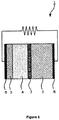
- FIG. 1 The basic structure of an exemplary all-solid-state battery (1) is illustrated in Figure 1 .
- it may mainly comprise the following parts:
- FIG. 1 Also shown in Figure 1 are the cathode current collector (5) and the anode current collector (6).
- a buffer layer (7) is interposed at cathode/solid electrolyte interface in order to enhance lithium-ion transfer at the interface, resulting in high-power batteries.
- high-resistance layers are developed at cathode/solid electrolyte interfaces because of the large chemical potential difference of lithium-ions.
- Such high-resistance layers can be resolved by the amorphous LiNbO 3 and LiTaO 3 buffer layers.
- US 7 993 782 discloses an all-solid lithium battery comprising a negative electrode, a lithium ion-conducting solid electrolyte as an electrolyte, and a positive electrode, wherein the lithium ion-conducting solid electrolyte is mainly composed of a sulfide, and the surface of a positive electrode active material is coated with a lithium ion-conducting oxide.
- the lithium ion-conducting oxide may contain lithium and one or both of niobium and tantalum.
- the present inventors have sought to develop new compositions for buffer layers to be used at the cathode / solid electrolyte interface, in particular in all-solid-state batteries, wherein the buffer layers would provide effective lithium ion conduction and avoid the problem of Li + -deficient layers, and also the inventors have sought to identify new materials suitable as solid electrolyte materials.
- ternary Li-Nb-Ta oxides having from 53 to 56 atom % of Li, from 15 to 30 atom % of Nb, and from 17 to 29 atom % of Ta.
- the invention therefore relates to a ternary mixed oxide of lithium, niobium and tantalum of formula (I): Li x Nb y Ta z O a (I) wherein:
- said mixed oxide shows:
- the said mixed oxide shows an ionic conductivity of at least 3.5 x 10 -6 S/cm, and/or a permittivity of at least 150.
- said mixed oxide in the mixed oxide of lithium, niobium and tantalum, said mixed oxide is partially amorphous.
- the present invention also relates to a process for preparing a mixed oxide of lithium, niobium and tantalum according to the present invention, wherein the process comprises the following steps:
- the present invention also relates to the use of the mixed oxide of lithium, niobium and tantalum according to the invention as a buffer layer between a positive electrode active material and a solid electrolyte, in a battery, or, in an alternative embodiment, as a solid electrolyte material in a battery.
- the present invention also relates to all-solid-state lithium batteries wherein the mixed oxides of the invention are used in either of these two roles.
- an appropriate production method includes a first preparation of a thin film, using methods such as a sol-gel process, physical vapour deposition or chemical vapour deposition.
- the Li-Nb-Ta oxide layer can be formed from an ethanol solution containing alkoxides of Li, Nb, and Ta.
- Li metal is dissolved in anhydrous ethanol under an Ar atmosphere, and then is mixed with niobium pentaethoxide and tantalum pentaethoxide.
- the solution is sprayed onto a substrate, and then annealed at an appropriate temperature.
- one example is r.f. magnetron sputtering, where a target of Li-Nb-Ta-O pellet is sputtered by an appropriate atmosphere (e.g. Ar or O 2 ) inside a vacuum chamber, and then the product thin film is deposited on a substrate (e.g. Au, Si/SiO 2 /TiO 2/ Pt).
- an appropriate atmosphere e.g. Ar or O 2
- the product thin film is deposited on a substrate (e.g. Au, Si/SiO 2 /TiO 2/ Pt).
- a thin film of Li-Nb-Ta oxide is generated, whose thickness is preferably at least 5 nm and at most 1000 nm, more preferably at least 10 nm and at most 500 nm.
- an annealing process is carried out, at a temperature of at least 300°C.
- a muffle oven where the sample can be annealed at desired temperatures.
- a tube furnace or a rapid thermal annealer can be also used, in which case the atmosphere can be easily controlled.
- an atmosphere not containing oxygen such as an inert atmosphere, which in a favourable embodiment may be an argon atmosphere.
- Annealing in oxygen appears to have a detrimental effect on the ionic conductivity of the final products, for as yet unclear reasons, at least for final products prepared based on a thin film laid down according to the method used in the experimental work set forth in the present application.
- other atmospheres e.g. air, O 2
- might be the best conditions in the case of other processing techniques e.g. sol-gel, chemical vapour deposition.
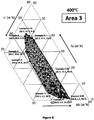
- Area 1 The compositions of "Area 1" show ionic conductivity larger than 3.5 x 10 -6 S/cm, and permittivity larger than 150 at the same time. When these materials are used as buffer layers at cathode/solid electrolyte interfaces in all-solid-state batteries, it is expected that the power density of batteries will increase most effectively.
- compositions of "Area 2" are effective after those of "Area 1".
- compositions of "Area 2" have either of the following properties.
- compositions of "Area 3" are effective after those of "Area 2".
- the compositions of "Area 3" have both ionic conductivity between 2 x 10 -6 S/cm and 3.5 x 10 -6 S/cm as well as permittivity of between 100 and 150.
- the metallic (not the oxygen) components there is between 53 and 56 atom% Li, between 15 and 30 atom% Nb, and between 17 and 29 atom% Ta.
- ternary oxide materials here Li-Nb-Ta oxides
- a temperature zone is reached which is between the glass transition temperature and the crystallisation temperature, such as to induce at least some reorganisation on a microscopic level.
- electron diffraction patterns show some clear dots implying partial, but not complete, crystallinity.
- the present invention relates to a mixed oxide of lithium, niobium and tantalum, wherein said mixed oxide is partially amorphous.
- a mixed oxide of lithium, niobium and tantalum as defined herein as a buffer layer between a positive electrode active material and a solid electrolyte, in a battery.
- the present invention thus relates to an all-solid-state lithium battery comprising the following elements:
- the buffer layer will appropriately have a thickness of at least 1 nanometre and at most 1 micrometre.
- the buffer layer may comprise particles of the said mixed oxide of lithium, niobium and tantalum, with a mean particle size of at most 0.5 micrometres.
- a mixed oxide of lithium, niobium and tantalum as defined herein may be used as a component making up part or all of the solid electrolyte itself.
- the mixed oxides of the present invention show higher conductivity than typical solid electrolytes such as LiPON and LiNbO 3 .
- the solid electrolyte comprises particles of the said mixed oxide of lithium, niobium and tantalum, with a mean particle size of at most 10 micrometres.
- the positive active material (cathode active material) used for the present invention which can be used in the positive electrode (cathode) active material layer, this is not especially limited if the average operating potential becomes more than 4 V (vs. Li/Li + ).
- the average operating potential of positive active material this is appropriately more than 4 V (vs. Li/Li + ), and it is preferable that it is within the limits of 4.0 V - 6.0 V, still more preferably within the limits of 4.5 V - 5.5 V.
- the average operating potential in the present invention can be evaluated using cyclic voltammetry, for example.
- the material is an oxide positive active material, which can have a high energy density.
- a compound which has the spinel type structure denoted by general formula LiM 2 O 4 (M is at least one kind of transition metal element), as an example of positive active material, can be mentioned as an example.
- M of the above-mentioned general formula LiM 2 O 4 especially if it is a transition metal element, it will not be limited, but it is preferable that it is at least one kind chosen from the group which consists of Ni, Mn, Cr, Co, V, and Ti, for example, and it is more preferable that it is at least one kind chosen from the group which consists of Ni, Mn, and Cr especially.
- LiCr 0.05 Ni 0.50 Mn 1.45 O 4 LiCrMnO 4 , LiNi 0.5 Mn 1.5 O 4 , etc.
- the compound which has the Olivine type structure denoted by general formula LiMPO 4 (M is at least one kind of transition metal element) as other examples of positive active material can be mentioned.
- M in the above-mentioned general formula will not be limited especially if it is a transition metal element, but it is preferable that it is at least one kind chosen from Mn, Co, Ni, and the group that consists of V, for example, and it is more preferable that it is at least one kind chosen from the group which consists of Mn, Co, and Ni especially.
- LiMnPO 4 , LiCoPO 4 , LiNiPO 4 , etc. can be mentioned.
- the compound which has the layer structure denoted by general formula LiMO 2 (M is at least 1 type of a transition metal element) as other examples of positive active material can be mentioned.
- LiNi 0.5 Mn 0.5 O 2 and LiNi 0.33 Co 0.33 Mn 0.33 O 2 etc. can be mentioned.
- a Li 2 MnO 3 -LiNi 1/3 Co 1/3 Mn 1/3 O 2 solid solution, a Li 2 MnO 3 -LiNi 0.5 Mn 1.5 O 2 solid solution, a Li 2 MnO 3 -LiFeO 2 solid solution, etc. can be mentioned.
- a particle shape such as the shape of a true ball and the shape of an elliptical ball, thin film form, etc. can be mentioned, as an example.
- the mean particle diameter when the positive active material has a particle shape, it is preferable that it is within the size range of 0.1 micrometer - 50 micrometers, for example.
- the content of the positive active material in a positive active material layer it is preferable that it is in the range of 10 % by weight to 99% by weight, for example, more preferably from 20 % by weight to 90% by weight.
- the positive active material layer in the present invention may contain other materials, for example, solid electrolyte materials etc.
- the content of the solid electrolyte materials in a positive active material layer it is preferable that this content is 1 % by weight to 90% by weight, more preferably 10 % by weight to 80% by weight.
- a positive active material layer may contain an electrically conductive agent from a viewpoint of improving the conductivity of a positive active material layer, other than the solid electrolyte materials mentioned above.
- electrically conductive material acetylene black, Ketjenblack, a carbon fiber, etc. can be mentioned, for example.
- a positive active material may also contain a binding agent.
- fluorine-based binding materials such as polyvinylidene fluoride (PVDF) and polytetrafluoroethylene (PTFE), etc. can be mentioned, for example.
- the thickness of a positive active material layer may change according to the kind of all-solid-state battery made, it is generally preferable that it is within the range of 0.1 micrometer - 1000 micrometers.
- the solid electrolyte layer in the present invention is formed between a positive active material layer and a negative electrode active material layer (and/or between a buffer layer, which coats the positive active material layer, and the negative electrode active material layer), and contains solid electrolyte materials.
- the relative dielectric constant of the solid electrolyte materials used for the present invention it is preferable that this value is lower than the relative dielectric constant of buffer layer material of the invention.
- solid electrolyte materials sulfide solid electrolyte materials, oxide solid electrolyte materials, etc. can be mentioned, for example.
- oxide solid electrolyte materials used for the present invention LiPON (for example, Li 2.9 PO 3.3 N 0.46 ), LiLaTiO (for example, Li 0.34 La 0.51 TiO 3 ), LiLaZrO (for example, Li 7 La 3 Zr 2 O 12 ), etc. can be mentioned. Especially, since membranes can be formed at a room temperature, especially LiPON is preferable.
- oxide solid electrolyte materials compounds which have NASICON mold structure can also be mentioned.
- the range of x it is preferable that it is 0.3 or more, and preferably 1.7 or less, more preferably 1.0 or less.
- the above-mentioned oxide solid electrolyte materials are Li 1.5 Al 0.5 Ge 1.5 (PO 4 ) 3 .
- the range of x it is preferably 0.3 or more, and preferably 1.7 or less, more preferably 1.0 or less.
- Particularly preferable solid electrolyte materials in the oxide group are Li 1.3 Al 0.3 Ti 1.7 (PO 4 ) 3 .
- Another possibility is a lithium borosilicate.
- the ternary Li-Nb-Ta oxides of the present invention may appropriately be used in barrier materials, between the cathode and the solid electrolyte layer, they may also themselves be components forming part or all of the electrolyte layer.
- possibilities include, for example, Li 10 GeP 2 S 12 , Li 2 S-P 2 S 5 and Li 2 S-P 2 S 5 -LiI, Li 2 S-P 2 S 5 -Li 2 O, Li 2 S-P 2 S 5 -Li 2 O-LiI, Li 2 S-SiS 2 and Li 2 S-SiS 2 -LiI, Li 2 S-SiS 2 -LiBr, Li 2 S-SiS 2 -LiCl, Li 2 S-SiS 2 -B 2 S 3 -LiI, Li 2 S-SiS 2 -P 2 S 5 -LiI, Li 2 S-B 2 S 3 , Li 2 S-P 2 S 5 -Z m S n (m and n being positive numbers, Z being Ge, Zn, or Ga), Li 2 S-GeS 2 and Li 2 S-SiS 2 -Li 3 PO 4 , and
- examples include a particle shape, such as the shape of a true ball and the shape of an elliptical ball, or a thin film form, for example.
- a particle shape such as the shape of a true ball and the shape of an elliptical ball, or a thin film form, for example.
- solid electrolyte materials have a particle shape, as for the mean particle diameter, it is preferable that their size is within the range of 50 nm to 5 micrometers, more preferably within the range of 100 nm to 3 micrometers.
- this layer may also contain a binding agent if needed.
- a binding agent used for a solid electrolyte layer this may be of the same type as mentioned above for the positive active material layer.
- this thickness is within the range of 0.1 micrometer to 1000 micrometers, more preferably within the range of 0.1 micrometer to 300 micrometers.
- this layer at least contains one or more negative electrode active material(s), and may additionally contain at least one or more of solid electrolyte materials and electrically conductive agents if needed.
- the negative electrode active material is not limited provided that occlusion and discharge of the Li ion, which is a conduction ion, are possible.
- a negative electrode active material a carbon active material, a metal active material, etc. can be mentioned, for example.
- a carbon active material black lead, meso carbon micro beads (MCMB), highly ordered / oriented pyrolytic graphite (HOPG), hard carbon, soft carbon, etc. can be mentioned as examples.
- a metal active material charges of an alloy, such as Li alloy and Sn-Co-C, In, Al, Si, Sn, etc. can be mentioned as examples.
- Oxide stock materials, such as Li 4 Ti 5 O 12 can be mentioned as examples of other negative electrode active materials.
- solid electrolyte materials used for the negative electrode active material layer may be the same as that for the solid electrolyte layer and positive active material layer mentioned above.
- the thickness of the negative electrode active material layer will generally be appropriately within the range of 0.1 micrometer to 1000 micrometers.
- An all-solid-state battery of the present invention has at least the positive active material layer, solid electrolyte layer, and negative electrode active material layer which were mentioned above. It further usually has a positive pole collector which collects a positive active material layer, and a negative pole collector which performs current collection of a negative electrode active material layer.
- a positive pole collector for example, SUS, aluminum, nickel, iron, titanium, carbon, etc. can be mentioned, and SUS is especially preferable.
- SUS As a material of a negative pole collector, SUS, copper, nickel, carbon, etc. can be mentioned, for example, and SUS is especially preferable. Concerning the thickness, form, etc.
- the cell case used for a common all-solid-state battery can be used as the cell case used for the present invention, for example, the cell case made from SUS, etc. can be mentioned.
- the all-solid-state battery of the present invention may form a power generation element in the inside of an insulating ring.
- the all-solid-state battery of the present invention can be considered as a chargeable and dischargeable all-solid-state battery in a room temperature environment. Although it may be a primary battery and may be a rechargeable battery as an all-solid-state battery of the present invention, it is especially preferable that it is a rechargeable battery. Concerning the form of the all-solid-state battery, a coin type, a laminated type, cylindrical, a square shape, etc. can be mentioned, as examples.
- the manufacturing method of the all-solid-state battery of the present invention is not particularly limited, and common manufacturing methods of all-solid-state batteries can be used.
- a positive active material layer can be formed on a substrate, the modification material layer mentioned above on the positive active material layer can be formed, and the method of forming a solid electrolyte layer and a negative electrode active material layer in order, and laminating them thereafter etc., may be used.
- the method for the preparation of Li-Nb-Ta oxide thin films described herein is a "physical vapour" co-deposition of the component elements using an appropriate geometric arrangement of elemental sources in a UHV environment.
- the metallic elements e.g. Li, Nb, Ta
- K-cells Knudsen cells
- e-guns Electron Beam Sources
- Oxygen (and other gaseous elements) is deposited using a plasma source.
- the presence of wedge shutters in the path of the elemental sources can be used to create thickness gradients of the component elements on the substrate.
- the rate of deposition is controlled by the temperature of the K-cell which is stable and reproducible. In an e-gun source, the power applied to the sample controls the deposition rate.
- the flow rate and plasma power control the deposition rate.
- the deposition rate as a function of position on the substrate is controlled by the wedge shutter.
- the incorporation of oxygen in the films is accomplished using a plasma atom source that converts O 2 (g) into a flux of oxygen atoms, radicals, and ions directed at the substrate. The process is illustrated in Figure 3 .
- the evaporation temperatures used for the metal components in K-cells are those that achieve a vapour pressure of around 10 -2 Torr (1.33 Pa). Elements with deposition temperatures above around 1250°C are usually evaporated using electron beam sources to achieve appreciable deposition rates.
- Lithium (granules, 99.9%, Sigma Aldrich) was evaporated from a 40 cm 3 pyrolytic boron nitride (PBN) crucible in a K-cell at temperatures ranging from 400 to 570°C.
- Niobium and Tantalum were evaporated using e-guns.
- Oxygen was incorporated into the films using an atom (i.e. plasma) source operating at a power ranging from 300 W to 600 W with an O 2 (g) flow rate ranging from 1 to 5 sccm.
- the substrates used throughout were 35 mm x 35 mm square wafers of approximately 1 mm thickness.
- the sample films were prepared on multilayer Si/SiO 2 /TiO 2 /Pt (SSTOP) (Nova Electronic Materials) at room temperature.
- SSTOP singlelayer Si/SiO 2 /TiO 2 /Pt
- the analysis of samples was carried out on a 14 x 14 grid with a pitch of 2.0 mm between analysis points.
- a 14 x 14 array of Pt contact pads with a diameter of 0.25 mm and a pitch of 2.0 mm were deposited using RF sputtering prior to removing the samples from the UHV system.
- the typical contact pad thickness was approximately 100 nm.
- the measurement process is illustrated in Figure 4 .
- the samples were heated to 300, 350, 400, 450, 500, and 550°C in Ar atmosphere using a High Throughput Optical Mapping of Phase Transitions (HTOMPT) instrument designed and constructed in-house.
- HTOMPT High Throughput Optical Mapping of Phase Transitions
- the HTOMPT instrument is a heated platen enclosed in a chamber with at view port located directly above the sample. Once assembled the chamber is air-tight and can be purged with inert gas (e.g., Ar) prior to heating the samples at a controlled rate.
- inert gas e.g., Ar
- the ionic conductivity was determined by measuring diameter of semi-arc observed at high frequency region in Nyquist plots, while the permittivity was determined at the frequency of 254 kHz.
- the protocol for making these measurements was as follows. Samples were transferred from either the UHV environment or the heating chamber (HTOMPT) and attached to a brass base plate with a small metal tab contacting to the surface of the platinum substrate to form a ground connection. The assembly was loaded onto the chuck of a Signatone probe station that was made insulating with a quartz plate and the enclosure was purged with Ar(g) throughout the measurements to reduce contact of the samples with the atmosphere.
- the platinum contact pads were addressed using a tungsten probe with a 25 ⁇ m tip diameter mounted on an arm that rotates in the vertical axis was used to ensure reproducible contact without piercing the films.
- the measurement process used to acquire impedance spectra from each point of the 14x14 array of samples is illustrated in Figure 4 .
- Impedance spectra were recorded in the range of 10 -6 Hz to 20 Hz with amplitude of 20 mV at each point using an Agilent 4284A Precision LCR Meter.
- the movement of the stage and operation of the LCR meter was coordinated and data recorded using in-house developed Labview® based instrument control software.
- the elemental compositions of samples were measured by Laser Ablation Inductively Coupled Plasma Mass Spectroscopy (ICP-MS) using a Perkin Elmer Elan 9000 ICP-MS equipped with a New Wave 213 nm laser.
- the ICP-MS analysis was done with reference to NIST 610 standard reference material.
- the sample thicknesses were measured by ellipsometry (Woollam M-200FI Spectroscopic Ellipsometer).
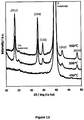
- the crystalline phase compositions were determined by X-ray diffraction (Bruker D8 diffractometer system equipped with a GADDS detector and a high intensity point source). The 2 ⁇ values quoted herein were measured using Cu K ⁇ radiation. A typical collection was done using a 2 ⁇ range from 20 to 52° and a collection time of 4 minutes for each field of a 14 x 14 array sample.
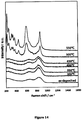
- the phase composition for the samples was also determined using Raman Spectroscopy (HORIBA Xplora). The use of XRD and Raman spectroscopy provides complementary information about crystalline and amorphous phases in the deposited materials.
- FIG. 5 shows ionic conductivities as a function of chemical composition of Li-Nb-Ta.
- the samples were annealed at 450°C.
- Figure 5(b) indicates that their ionic conductivity do not change dramatically when Ta / (Ta + Nb) ratio exceeds 0.2.
- Examples according to the invention are ones showing ternary Li-Nb-Ta oxides having from 53 to 56 atom % of Li, from 15 to 30 atom % of Nb, and from 17 to 29 atom % of Ta.
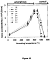
- annealing temperatures were studied. As shown in Figs. 11 and 12 , annealing at around 400 and 450°C, using the annealing chamber setup used in the present series of experiments, could offer maximum ionic conductivity as well as permittivity at the same time. This is probably because morphologies in materials are most appropriate for lithium-ion conduction when annealed at these temperatures. As will be shown later, these materials have an amorphous state or partially crystalline state.
- LiNbO 3 and LiTaO 3 in an amorphous state exhibit ionic conductivity with almost no permittivity, whereas in their crystal state they exhibit large permittivity with no conductivity. Therefore, it was unexpected that the materials of the present invention would exhibit both the highest ionic conductivity and permittivity when they are annealed at around 400 and 450°C.
- the samples were analyzed by XRD, Raman, and TEM to obtain further structural information.
- the XRD analysis confirmed that the materials have crystal structure assigned as a space group of R3c(161) with a rhombohedral lattice.
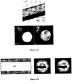
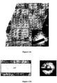
- TEM images were taken to observe morphology and crystallinity in samples.
- the sample was annealed at 550°C, clear spots were observed in electron diffraction patterns as shown in Fig. 16 , indicating that the sample consists of crystal phases. Such crystals had small ionic conductivity and permittivity.
- the electron diffraction patterns showed weak spots due to small crystallines when annealed at 450°C as shown in Fig. 15 . It may be noted that the intensity of electron diffraction spots depended on chemical composition; in fact, no spot was observed in Fig. 17 even though the annealed temperature was 450°C.
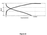
- a solid state battery comprising of a lithium manganese nickel oxide cathode (356 nm, 30.8 at. % Li, 48.8 at. % Mn and 20.4 at. % Ni), a lithium niobium tantalate buffer layer (15 nm, 57.7 at. % Li, 24.8 at. % Nb and 17.5 at. % Ta) a lithium borosilicate solid electrolyte (813 nm, 79.8 at. % Li, 9.3 at. % B and 10.7 at.
Landscapes
- Chemical & Material Sciences (AREA)
- Engineering & Computer Science (AREA)
- Manufacturing & Machinery (AREA)
- Organic Chemistry (AREA)
- Ceramic Engineering (AREA)
- Chemical Kinetics & Catalysis (AREA)
- Electrochemistry (AREA)
- Materials Engineering (AREA)
- Inorganic Chemistry (AREA)
- General Chemical & Material Sciences (AREA)
- Structural Engineering (AREA)
- Composite Materials (AREA)
- Physics & Mathematics (AREA)
- Condensed Matter Physics & Semiconductors (AREA)
- General Physics & Mathematics (AREA)
- Mechanical Engineering (AREA)
- Metallurgy (AREA)
- Dispersion Chemistry (AREA)
- Secondary Cells (AREA)
Claims (16)
- Mischoxid von Lithium, Niob und Tantal der Formel (I):
LixNbyTazOa (I)
wobei das Mischoxid ein ternäres Li-Nb-Ta-Oxid ist, in welchem 0,53 ≤ x ≤ 0,56,- 0,15 ≤ y ≤ 0,30 und- 0,17 ≤ z ≤ 0,29,wobei x + y + z = 1,00 und
a ≤ 3,00 gilt. - Mischoxid von Lithium, Niob und Tantal nach Anspruch 1, wobei das Mischoxid:- eine ionische Leitfähigkeit von mindestens 2,0 x 10⁻⁶ S/cm und- eine Permittivität, bei 254 kHz berechnet, von mindestens 100 aufweist.
- Mischoxid nach Anspruch 2, wobei das Mischoxid eine ionische Leitfähigkeit von mindestens 3,5 x 10⁻⁶ S/cm aufweist.
- Mischoxid nach Anspruch 2 oder 3, wobei das Mischoxid eine Permittivität, bei 254 kHz berechnet, von mindestens 150 aufweist.
- Mischoxid von Lithium, Niob und Tantal nach einem der Ansprüche 1 bis 4, wobei das Mischoxid teilweise amorph ist.
- Verfahren zum Herstellen eines Mischoxids von Lithium, Niob und Tantal nach einem der Ansprüche 1 bis 5, wobei das Verfahren die folgenden Schritte umfasst:- eine Dünnschicht von Li-, Nb- und Ta-Oxid wird hergestellt,- ein Glühvorgang wird bei einer Temperatur von mindestens 300 °C ausgeführt.
- Verfahren nach Anspruch 6, wobei die Schicht eine Dicke von mindestens 5 nm und höchstens 1000 nm, noch bevorzugter mindestens 10 nm und höchstens 500 nm aufweist.
- Verfahren nach Anspruch 6 oder 7, wobei die Dünnschicht durch ein Sol-Gel-Verfahren, durch physikalische Gasphasenabscheidung oder durch chemische Gasphasenabscheidung hergestellt wird.
- Verfahren nach einem der Ansprüche 6 bis 8, wobei der Glühvorgang in einer Argonatmosphäre ausgeführt wird.
- Ganzfestkörper-Lithiumbatterie, umfassend die folgenden Elemente:- eine Positivelektroden-Aktivmaterialschicht,- eine Pufferschicht,- einen festen Elektrolyt,- eine Negativelektroden-Aktivmaterialschicht,wobei die Pufferschicht, die als Zwischenstück zwischen dem Positivelektroden-Aktivmaterial und dem festen Elektrolyt wirkt, ein Mischoxid von Lithium, Niob und Tantal, wie in einem der Ansprüche 1 bis 5 definiert, enthält.
- Ganzfestkörper-Lithiumbatterie nach Anspruch 10, wobei die Pufferschicht eine Dicke von mindestens 1 Nanometer und höchstens 1 Mikrometer aufweist.
- Ganzfestkörper-Lithiumbatterie nach Anspruch 10 oder 11, wobei die Pufferschicht Teilchen des Mischoxids von Lithium, Niob und Tantal mit einer mittleren Teilchengröße von höchstens 0,5 Mikrometern umfasst.
- Ganzfestkörper-Lithiumbatterie, umfassend die folgenden Elemente:- eine Positivelektroden-Aktivmaterialschicht,- einen festen Elektrolyt,- eine Negativelektroden-Aktivmaterialschicht,wobei der feste Elektrolyt ein Mischoxid von Lithium, Niob und Tantal, wie in einem der Ansprüche 1 bis 5 definiert, enthält.
- Ganzfestkörper-Lithiumbatterie nach Anspruch 13, wobei der feste Elektrolyt Teilchen des Mischoxids von Lithium, Niob und Tantal mit einer mittleren Teilchengröße von höchstens 10 Mikrometern umfasst.
- Verwendung eines Mischoxids von Lithium, Niob und Tantal, wie in einem der Ansprüche 1 bis 5 definiert, als Pufferschicht zwischen einem Positivelektroden-Aktivmaterial und einem festen Elektrolyt, in einer Batterie.
- Verwendung eines Mischoxids von Lithium, Niob und Tantal, wie in einem der Ansprüche 1 bis 5 definiert, als festes Elektrolytmaterial in einer Batterie.
Applications Claiming Priority (1)
| Application Number | Priority Date | Filing Date | Title |
|---|---|---|---|
| PCT/EP2014/061603 WO2015185129A1 (en) | 2014-06-04 | 2014-06-04 | Lithium-ion conductive ceramics |
Publications (2)
| Publication Number | Publication Date |
|---|---|
| EP3152183A1 EP3152183A1 (de) | 2017-04-12 |
| EP3152183B1 true EP3152183B1 (de) | 2020-04-15 |
Family
ID=50942667
Family Applications (1)
| Application Number | Title | Priority Date | Filing Date |
|---|---|---|---|
| EP14730115.4A Active EP3152183B1 (de) | 2014-06-04 | 2014-06-04 | Leitende lithium-ionen-keramik |
Country Status (2)
| Country | Link |
|---|---|
| EP (1) | EP3152183B1 (de) |
| WO (1) | WO2015185129A1 (de) |
Families Citing this family (10)
| Publication number | Priority date | Publication date | Assignee | Title |
|---|---|---|---|---|
| JP6323475B2 (ja) | 2016-02-26 | 2018-05-16 | トヨタ自動車株式会社 | 複合活物質、固体電池および複合活物質の製造方法 |
| WO2017216532A1 (en) * | 2016-06-15 | 2017-12-21 | Ilika Technologies Limited | Lithium borosilicate glass as electrolyte and electrode protective layer |
| WO2018224334A1 (en) | 2017-06-09 | 2018-12-13 | Robert Bosch Gmbh | Battery cell with anode protective layer |
| US10734674B2 (en) | 2017-08-14 | 2020-08-04 | Thinika, Llc | Solid-state thin film hybrid electrochemical cell |
| KR102470105B1 (ko) * | 2017-08-14 | 2022-11-22 | 티니카, 엘엘씨 | 고체상 박막 하이브리드 전기 화학 전지 |
| GB2575786B (en) * | 2018-07-20 | 2021-11-03 | Dyson Technology Ltd | Stack for an energy storage device |
| RU2709487C1 (ru) * | 2018-08-14 | 2019-12-18 | Общество с ограниченной ответственностью "Финика" | Твердотельный тонкопленочный гибридный электрохимический источник тока |
| CN110002875A (zh) * | 2019-05-09 | 2019-07-12 | 南昌航空大学 | 一种利用钽改性铌酸钠-锆酸钙基反铁电陶瓷储能的方法 |
| JP7271376B2 (ja) | 2019-09-13 | 2023-05-11 | 株式会社東芝 | 複合酸化物、活物質複合材料、電極、電池、電池パック、及び車両 |
| CN111106392A (zh) * | 2019-12-30 | 2020-05-05 | 华南师范大学 | 全固态电解质电池的制备方法 |
Family Cites Families (4)
| Publication number | Priority date | Publication date | Assignee | Title |
|---|---|---|---|---|
| US4001076A (en) * | 1974-12-11 | 1977-01-04 | Gte Laboratories Incorporated | Method for growing thin epitaxial layers of a non-linear, optically active material |
| US4951293A (en) | 1988-05-26 | 1990-08-21 | Matsushita Electric Industrial Co., Ltd | Frequency doubled laser apparatus |
| WO2007004590A1 (ja) | 2005-07-01 | 2007-01-11 | National Institute For Materials Science | 全固体リチウム電池 |
| JP5623360B2 (ja) | 2011-09-13 | 2014-11-12 | トヨタ自動車株式会社 | 全固体電池 |
-
2014
- 2014-06-04 EP EP14730115.4A patent/EP3152183B1/de active Active
- 2014-06-04 WO PCT/EP2014/061603 patent/WO2015185129A1/en not_active Ceased
Non-Patent Citations (1)
| Title |
|---|
| None * |
Also Published As
| Publication number | Publication date |
|---|---|
| WO2015185129A1 (en) | 2015-12-10 |
| EP3152183A1 (de) | 2017-04-12 |
Similar Documents
| Publication | Publication Date | Title |
|---|---|---|
| EP3152183B1 (de) | Leitende lithium-ionen-keramik | |
| JP7435452B2 (ja) | 硫化物固体電解質の製造方法、硫化物固体電解質、全固体電池、及び硫化物固体電解質の製造に用いる原料化合物の選択方法 | |
| EP3472881B1 (de) | Lithium-borosilikat-glas als elektrolyt und elektroden-schutzschicht | |
| Du et al. | Recent advances in the interface engineering of solid-state Li-ion batteries with artificial buffer layers: challenges, materials, construction, and characterization | |
| US10879558B2 (en) | Materials for solid electrolyte | |
| CN100435389C (zh) | 锂二次电池负极构成材料及其制造方法 | |
| CN101395754B (zh) | 电池结构体以及使用该电池结构体的锂二次电池 | |
| US20030088971A1 (en) | Encapsulated alloy electrodes | |
| EP1217682A2 (de) | Verfahren zur Herstellung von festen anorganischen Elektrolytdünnschichten | |
| JP2011065887A (ja) | 正極材料、その製造方法及びリチウムイオン電池 | |
| US11851742B2 (en) | Vapor deposition method for preparing an amorphous lithium borosilicate | |
| KR20130004491A (ko) | 정극 활물질 | |
| EP2445050B1 (de) | Element zur erzeugung von elektrizität und dieses enthaltende batterie mit wasserfreiem elektrolyt | |
| Dai et al. | All-solid-state thin-film batteries based on lithium phosphorus oxynitrides | |
| JP2006156284A (ja) | リチウムイオン導電体およびそれを用いた二次電池 | |
| JP2004220906A (ja) | リチウム二次電池負極部材、及びその製造方法 | |
| US11161740B2 (en) | Method of synthesis of LiTi2(PS4)3 | |
| US9379415B2 (en) | Entire solid lithium secondary battery | |
| EP4070395B1 (de) | Verfahren | |
| Touré et al. | Lanthanum niobate perovskite thin films for Li-ion microbatteries | |
| HK1126573A (en) | Battery structure and lithium secondary battery using the same |
Legal Events
| Date | Code | Title | Description |
|---|---|---|---|
| STAA | Information on the status of an ep patent application or granted ep patent |
Free format text: STATUS: THE INTERNATIONAL PUBLICATION HAS BEEN MADE |
|
| PUAI | Public reference made under article 153(3) epc to a published international application that has entered the european phase |
Free format text: ORIGINAL CODE: 0009012 |
|
| STAA | Information on the status of an ep patent application or granted ep patent |
Free format text: STATUS: REQUEST FOR EXAMINATION WAS MADE |
|
| 17P | Request for examination filed |
Effective date: 20161122 |
|
| AK | Designated contracting states |
Kind code of ref document: A1 Designated state(s): AL AT BE BG CH CY CZ DE DK EE ES FI FR GB GR HR HU IE IS IT LI LT LU LV MC MK MT NL NO PL PT RO RS SE SI SK SM TR |
|
| AX | Request for extension of the european patent |
Extension state: BA ME |
|
| DAX | Request for extension of the european patent (deleted) | ||
| STAA | Information on the status of an ep patent application or granted ep patent |
Free format text: STATUS: EXAMINATION IS IN PROGRESS |
|
| 17Q | First examination report despatched |
Effective date: 20181206 |
|
| RIC1 | Information provided on ipc code assigned before grant |
Ipc: H01M 4/36 20060101ALI20191120BHEP Ipc: H01M 10/0562 20100101ALI20191120BHEP Ipc: C23C 14/08 20060101ALI20191120BHEP Ipc: C04B 35/495 20060101AFI20191120BHEP Ipc: C01G 35/00 20060101ALI20191120BHEP Ipc: H01M 10/052 20100101ALI20191120BHEP Ipc: H01M 4/485 20100101ALI20191120BHEP Ipc: C04B 35/624 20060101ALI20191120BHEP Ipc: H01M 4/131 20100101ALI20191120BHEP Ipc: C04B 35/622 20060101ALI20191120BHEP |
|
| GRAP | Despatch of communication of intention to grant a patent |
Free format text: ORIGINAL CODE: EPIDOSNIGR1 |
|
| STAA | Information on the status of an ep patent application or granted ep patent |
Free format text: STATUS: GRANT OF PATENT IS INTENDED |
|
| INTG | Intention to grant announced |
Effective date: 20200107 |
|
| GRAS | Grant fee paid |
Free format text: ORIGINAL CODE: EPIDOSNIGR3 |
|
| GRAA | (expected) grant |
Free format text: ORIGINAL CODE: 0009210 |
|
| STAA | Information on the status of an ep patent application or granted ep patent |
Free format text: STATUS: THE PATENT HAS BEEN GRANTED |
|
| AK | Designated contracting states |
Kind code of ref document: B1 Designated state(s): AL AT BE BG CH CY CZ DE DK EE ES FI FR GB GR HR HU IE IS IT LI LT LU LV MC MK MT NL NO PL PT RO RS SE SI SK SM TR |
|
| REG | Reference to a national code |
Ref country code: CH Ref legal event code: EP |
|
| REG | Reference to a national code |
Ref country code: DE Ref legal event code: R096 Ref document number: 602014063775 Country of ref document: DE |
|
| REG | Reference to a national code |
Ref country code: IE Ref legal event code: FG4D |
|
| REG | Reference to a national code |
Ref country code: AT Ref legal event code: REF Ref document number: 1257101 Country of ref document: AT Kind code of ref document: T Effective date: 20200515 |
|
| REG | Reference to a national code |
Ref country code: DE Ref legal event code: R082 Ref document number: 602014063775 Country of ref document: DE Representative=s name: CBDL PATENTANWAELTE, DE Ref country code: DE Ref legal event code: R081 Ref document number: 602014063775 Country of ref document: DE Owner name: TOYOTA JIDOSHA KABUSHIKI KAISHA, TOYOTA-SHI, JP Free format text: FORMER OWNER: TOYOTA MOTOR EUROPE NV/SA, BRUSSEL, BE |
|
| RAP2 | Party data changed (patent owner data changed or rights of a patent transferred) |
Owner name: TOYOTA JIDOSHA KABUSHIKI KAISHA |
|
| REG | Reference to a national code |
Ref country code: NL Ref legal event code: MP Effective date: 20200415 |
|
| REG | Reference to a national code |
Ref country code: LT Ref legal event code: MG4D |
|
| REG | Reference to a national code |
Ref country code: GB Ref legal event code: 732E Free format text: REGISTERED BETWEEN 20200911 AND 20200916 |
|
| PG25 | Lapsed in a contracting state [announced via postgrant information from national office to epo] |
Ref country code: NO Free format text: LAPSE BECAUSE OF FAILURE TO SUBMIT A TRANSLATION OF THE DESCRIPTION OR TO PAY THE FEE WITHIN THE PRESCRIBED TIME-LIMIT Effective date: 20200715 Ref country code: GR Free format text: LAPSE BECAUSE OF FAILURE TO SUBMIT A TRANSLATION OF THE DESCRIPTION OR TO PAY THE FEE WITHIN THE PRESCRIBED TIME-LIMIT Effective date: 20200716 Ref country code: IS Free format text: LAPSE BECAUSE OF FAILURE TO SUBMIT A TRANSLATION OF THE DESCRIPTION OR TO PAY THE FEE WITHIN THE PRESCRIBED TIME-LIMIT Effective date: 20200815 Ref country code: SE Free format text: LAPSE BECAUSE OF FAILURE TO SUBMIT A TRANSLATION OF THE DESCRIPTION OR TO PAY THE FEE WITHIN THE PRESCRIBED TIME-LIMIT Effective date: 20200415 Ref country code: FI Free format text: LAPSE BECAUSE OF FAILURE TO SUBMIT A TRANSLATION OF THE DESCRIPTION OR TO PAY THE FEE WITHIN THE PRESCRIBED TIME-LIMIT Effective date: 20200415 Ref country code: LT Free format text: LAPSE BECAUSE OF FAILURE TO SUBMIT A TRANSLATION OF THE DESCRIPTION OR TO PAY THE FEE WITHIN THE PRESCRIBED TIME-LIMIT Effective date: 20200415 Ref country code: PT Free format text: LAPSE BECAUSE OF FAILURE TO SUBMIT A TRANSLATION OF THE DESCRIPTION OR TO PAY THE FEE WITHIN THE PRESCRIBED TIME-LIMIT Effective date: 20200817 Ref country code: NL Free format text: LAPSE BECAUSE OF FAILURE TO SUBMIT A TRANSLATION OF THE DESCRIPTION OR TO PAY THE FEE WITHIN THE PRESCRIBED TIME-LIMIT Effective date: 20200415 |
|
| REG | Reference to a national code |
Ref country code: AT Ref legal event code: MK05 Ref document number: 1257101 Country of ref document: AT Kind code of ref document: T Effective date: 20200415 |
|
| PG25 | Lapsed in a contracting state [announced via postgrant information from national office to epo] |
Ref country code: BG Free format text: LAPSE BECAUSE OF FAILURE TO SUBMIT A TRANSLATION OF THE DESCRIPTION OR TO PAY THE FEE WITHIN THE PRESCRIBED TIME-LIMIT Effective date: 20200715 Ref country code: HR Free format text: LAPSE BECAUSE OF FAILURE TO SUBMIT A TRANSLATION OF THE DESCRIPTION OR TO PAY THE FEE WITHIN THE PRESCRIBED TIME-LIMIT Effective date: 20200415 Ref country code: RS Free format text: LAPSE BECAUSE OF FAILURE TO SUBMIT A TRANSLATION OF THE DESCRIPTION OR TO PAY THE FEE WITHIN THE PRESCRIBED TIME-LIMIT Effective date: 20200415 Ref country code: LV Free format text: LAPSE BECAUSE OF FAILURE TO SUBMIT A TRANSLATION OF THE DESCRIPTION OR TO PAY THE FEE WITHIN THE PRESCRIBED TIME-LIMIT Effective date: 20200415 |
|
| PG25 | Lapsed in a contracting state [announced via postgrant information from national office to epo] |
Ref country code: AL Free format text: LAPSE BECAUSE OF FAILURE TO SUBMIT A TRANSLATION OF THE DESCRIPTION OR TO PAY THE FEE WITHIN THE PRESCRIBED TIME-LIMIT Effective date: 20200415 |
|
| REG | Reference to a national code |
Ref country code: DE Ref legal event code: R097 Ref document number: 602014063775 Country of ref document: DE |
|
| PG25 | Lapsed in a contracting state [announced via postgrant information from national office to epo] |
Ref country code: AT Free format text: LAPSE BECAUSE OF FAILURE TO SUBMIT A TRANSLATION OF THE DESCRIPTION OR TO PAY THE FEE WITHIN THE PRESCRIBED TIME-LIMIT Effective date: 20200415 Ref country code: MC Free format text: LAPSE BECAUSE OF FAILURE TO SUBMIT A TRANSLATION OF THE DESCRIPTION OR TO PAY THE FEE WITHIN THE PRESCRIBED TIME-LIMIT Effective date: 20200415 Ref country code: EE Free format text: LAPSE BECAUSE OF FAILURE TO SUBMIT A TRANSLATION OF THE DESCRIPTION OR TO PAY THE FEE WITHIN THE PRESCRIBED TIME-LIMIT Effective date: 20200415 Ref country code: SM Free format text: LAPSE BECAUSE OF FAILURE TO SUBMIT A TRANSLATION OF THE DESCRIPTION OR TO PAY THE FEE WITHIN THE PRESCRIBED TIME-LIMIT Effective date: 20200415 Ref country code: DK Free format text: LAPSE BECAUSE OF FAILURE TO SUBMIT A TRANSLATION OF THE DESCRIPTION OR TO PAY THE FEE WITHIN THE PRESCRIBED TIME-LIMIT Effective date: 20200415 Ref country code: IT Free format text: LAPSE BECAUSE OF FAILURE TO SUBMIT A TRANSLATION OF THE DESCRIPTION OR TO PAY THE FEE WITHIN THE PRESCRIBED TIME-LIMIT Effective date: 20200415 Ref country code: RO Free format text: LAPSE BECAUSE OF FAILURE TO SUBMIT A TRANSLATION OF THE DESCRIPTION OR TO PAY THE FEE WITHIN THE PRESCRIBED TIME-LIMIT Effective date: 20200415 Ref country code: CZ Free format text: LAPSE BECAUSE OF FAILURE TO SUBMIT A TRANSLATION OF THE DESCRIPTION OR TO PAY THE FEE WITHIN THE PRESCRIBED TIME-LIMIT Effective date: 20200415 Ref country code: ES Free format text: LAPSE BECAUSE OF FAILURE TO SUBMIT A TRANSLATION OF THE DESCRIPTION OR TO PAY THE FEE WITHIN THE PRESCRIBED TIME-LIMIT Effective date: 20200415 |
|
| REG | Reference to a national code |
Ref country code: CH Ref legal event code: PL |
|
| PLBE | No opposition filed within time limit |
Free format text: ORIGINAL CODE: 0009261 |
|
| STAA | Information on the status of an ep patent application or granted ep patent |
Free format text: STATUS: NO OPPOSITION FILED WITHIN TIME LIMIT |
|
| PG25 | Lapsed in a contracting state [announced via postgrant information from national office to epo] |
Ref country code: PL Free format text: LAPSE BECAUSE OF FAILURE TO SUBMIT A TRANSLATION OF THE DESCRIPTION OR TO PAY THE FEE WITHIN THE PRESCRIBED TIME-LIMIT Effective date: 20200415 Ref country code: SK Free format text: LAPSE BECAUSE OF FAILURE TO SUBMIT A TRANSLATION OF THE DESCRIPTION OR TO PAY THE FEE WITHIN THE PRESCRIBED TIME-LIMIT Effective date: 20200415 |
|
| 26N | No opposition filed |
Effective date: 20210118 |
|
| PG25 | Lapsed in a contracting state [announced via postgrant information from national office to epo] |
Ref country code: LU Free format text: LAPSE BECAUSE OF NON-PAYMENT OF DUE FEES Effective date: 20200604 |
|
| REG | Reference to a national code |
Ref country code: BE Ref legal event code: MM Effective date: 20200630 |
|
| PG25 | Lapsed in a contracting state [announced via postgrant information from national office to epo] |
Ref country code: CH Free format text: LAPSE BECAUSE OF NON-PAYMENT OF DUE FEES Effective date: 20200630 Ref country code: LI Free format text: LAPSE BECAUSE OF NON-PAYMENT OF DUE FEES Effective date: 20200630 Ref country code: IE Free format text: LAPSE BECAUSE OF NON-PAYMENT OF DUE FEES Effective date: 20200604 |
|
| PG25 | Lapsed in a contracting state [announced via postgrant information from national office to epo] |
Ref country code: BE Free format text: LAPSE BECAUSE OF NON-PAYMENT OF DUE FEES Effective date: 20200630 Ref country code: SI Free format text: LAPSE BECAUSE OF FAILURE TO SUBMIT A TRANSLATION OF THE DESCRIPTION OR TO PAY THE FEE WITHIN THE PRESCRIBED TIME-LIMIT Effective date: 20200415 |
|
| PG25 | Lapsed in a contracting state [announced via postgrant information from national office to epo] |
Ref country code: TR Free format text: LAPSE BECAUSE OF FAILURE TO SUBMIT A TRANSLATION OF THE DESCRIPTION OR TO PAY THE FEE WITHIN THE PRESCRIBED TIME-LIMIT Effective date: 20200415 Ref country code: MT Free format text: LAPSE BECAUSE OF FAILURE TO SUBMIT A TRANSLATION OF THE DESCRIPTION OR TO PAY THE FEE WITHIN THE PRESCRIBED TIME-LIMIT Effective date: 20200415 Ref country code: CY Free format text: LAPSE BECAUSE OF FAILURE TO SUBMIT A TRANSLATION OF THE DESCRIPTION OR TO PAY THE FEE WITHIN THE PRESCRIBED TIME-LIMIT Effective date: 20200415 |
|
| PG25 | Lapsed in a contracting state [announced via postgrant information from national office to epo] |
Ref country code: MK Free format text: LAPSE BECAUSE OF FAILURE TO SUBMIT A TRANSLATION OF THE DESCRIPTION OR TO PAY THE FEE WITHIN THE PRESCRIBED TIME-LIMIT Effective date: 20200415 |
|
| REG | Reference to a national code |
Ref country code: DE Ref legal event code: R082 Ref document number: 602014063775 Country of ref document: DE Representative=s name: CBDL PATENTANWAELTE GBR, DE Ref country code: DE Ref legal event code: R082 Ref document number: 602014063775 Country of ref document: DE Representative=s name: CBDL PATENTANWAELTE EGBR, DE |
|
| P01 | Opt-out of the competence of the unified patent court (upc) registered |
Effective date: 20230427 |
|
| REG | Reference to a national code |
Ref country code: DE Ref legal event code: R084 Ref document number: 602014063775 Country of ref document: DE |
|
| REG | Reference to a national code |
Ref country code: GB Ref legal event code: 746 Effective date: 20231113 |
|
| PGFP | Annual fee paid to national office [announced via postgrant information from national office to epo] |
Ref country code: DE Payment date: 20250402 Year of fee payment: 12 |
|
| PGFP | Annual fee paid to national office [announced via postgrant information from national office to epo] |
Ref country code: GB Payment date: 20250401 Year of fee payment: 12 |
|
| PGFP | Annual fee paid to national office [announced via postgrant information from national office to epo] |
Ref country code: FR Payment date: 20250401 Year of fee payment: 12 |