EP3149335B1 - Schraubenverdichter - Google Patents
Schraubenverdichter Download PDFInfo
- Publication number
- EP3149335B1 EP3149335B1 EP15728361.5A EP15728361A EP3149335B1 EP 3149335 B1 EP3149335 B1 EP 3149335B1 EP 15728361 A EP15728361 A EP 15728361A EP 3149335 B1 EP3149335 B1 EP 3149335B1
- Authority
- EP
- European Patent Office
- Prior art keywords
- compressor
- rotor
- refrigerant
- heat exchanger
- lobes
- Prior art date
- Legal status (The legal status is an assumption and is not a legal conclusion. Google has not performed a legal analysis and makes no representation as to the accuracy of the status listed.)
- Active
Links
Images

Classifications
-
- F—MECHANICAL ENGINEERING; LIGHTING; HEATING; WEAPONS; BLASTING
- F04—POSITIVE - DISPLACEMENT MACHINES FOR LIQUIDS; PUMPS FOR LIQUIDS OR ELASTIC FLUIDS
- F04C—ROTARY-PISTON, OR OSCILLATING-PISTON, POSITIVE-DISPLACEMENT MACHINES FOR LIQUIDS; ROTARY-PISTON, OR OSCILLATING-PISTON, POSITIVE-DISPLACEMENT PUMPS
- F04C18/00—Rotary-piston pumps specially adapted for elastic fluids
- F04C18/08—Rotary-piston pumps specially adapted for elastic fluids of intermeshing-engagement type, i.e. with engagement of co-operating members similar to that of toothed gearing
- F04C18/082—Details specially related to intermeshing engagement type pumps
- F04C18/084—Toothed wheels
-
- F—MECHANICAL ENGINEERING; LIGHTING; HEATING; WEAPONS; BLASTING
- F04—POSITIVE - DISPLACEMENT MACHINES FOR LIQUIDS; PUMPS FOR LIQUIDS OR ELASTIC FLUIDS
- F04C—ROTARY-PISTON, OR OSCILLATING-PISTON, POSITIVE-DISPLACEMENT MACHINES FOR LIQUIDS; ROTARY-PISTON, OR OSCILLATING-PISTON, POSITIVE-DISPLACEMENT PUMPS
- F04C18/00—Rotary-piston pumps specially adapted for elastic fluids
- F04C18/08—Rotary-piston pumps specially adapted for elastic fluids of intermeshing-engagement type, i.e. with engagement of co-operating members similar to that of toothed gearing
- F04C18/12—Rotary-piston pumps specially adapted for elastic fluids of intermeshing-engagement type, i.e. with engagement of co-operating members similar to that of toothed gearing of other than internal-axis type
- F04C18/14—Rotary-piston pumps specially adapted for elastic fluids of intermeshing-engagement type, i.e. with engagement of co-operating members similar to that of toothed gearing of other than internal-axis type with toothed rotary pistons
- F04C18/16—Rotary-piston pumps specially adapted for elastic fluids of intermeshing-engagement type, i.e. with engagement of co-operating members similar to that of toothed gearing of other than internal-axis type with toothed rotary pistons with helical teeth, e.g. chevron-shaped, screw type
-
- F—MECHANICAL ENGINEERING; LIGHTING; HEATING; WEAPONS; BLASTING
- F04—POSITIVE - DISPLACEMENT MACHINES FOR LIQUIDS; PUMPS FOR LIQUIDS OR ELASTIC FLUIDS
- F04C—ROTARY-PISTON, OR OSCILLATING-PISTON, POSITIVE-DISPLACEMENT MACHINES FOR LIQUIDS; ROTARY-PISTON, OR OSCILLATING-PISTON, POSITIVE-DISPLACEMENT PUMPS
- F04C23/00—Combinations of two or more pumps, each being of rotary-piston or oscillating-piston type, specially adapted for elastic fluids; Pumping installations specially adapted for elastic fluids; Multi-stage pumps specially adapted for elastic fluids
- F04C23/008—Hermetic pumps
Definitions
- the disclosure relates to screw compressors. More particularly, the disclosure relates to twin-rotor hermetic or semi-hermetic compressors.
- US Patent No. 7,163,387 discloses a twin-rotor compressor rotor lobe geometry.
- the illustrated compressor has a five-lobed male rotor and a six-lobed female rotor.
- Other known asymmetric twin rotor compressors have a five-lobed male rotor and a seven-lobed female rotor or six-lobed male rotor and a seven-lobed female rotor.
- a compressor comprises a housing having a first port and a second port.
- a male rotor has a working portion having a plurality of lobes of a count and at least a first shaft portion protruding beyond a first end of the male rotor working portion and mounted for rotation about a first axis.
- a female rotor has a working portion having a plurality of lobes of a count (N F ) and mounted for rotation about a second axis so as to be enmeshed with the male rotor working portion.
- An electric motor is within the housing and has a stator and a rotor mounted to the first shaft portion.
- the lobe count of the male rotor is seven and the lobe count of the female rotor is eight.
- the tip-to-root ratio of the lobes of the female rotor is 1.49:1 to 1.50:1 and the tip-to-root ratio of the lobes of the male rotor is 1.41:1 to 1.42:1.
- the compressor has no additional compressor rotors.
- US 2013/108495 A1 shows a compressor for compressing refrigerant in a refrigerant circuit includes a housing defining a compression chamber.
- a screw rotor is mounted within the housing and configured to form a pocket of high pressure refrigerant and a pocket of low pressure refrigerant within the compression chamber.
- the screw rotor has a rotor shaft rotating about an axis.
- a bearing cavity includes at least one bearing rotatably supporting the rotor shaft.
- a partition through which the rotor shaft extends separates the bearing cavity from the compression chamber.
- a contacting seal is sealingly engaged with the rotor shaft and disposed in the bearing cavity proximate the partition.
- DE 102 58 145 A1 shows a screw compressor with two rotors positioned in a compressor housing, the two rotors compress a refrigerant.
- the compressor housing shows an inlet for adding additional refrigerant to further cool the screw compressor.
- a full-load volume index is 1.7-4.0.
- the first shaft portion is cantilevered from a bearing between the first shaft portion and the male rotor working portion.
- a method for using the compressor comprises running the compressor at a speed of at least 90Hz.
- the running of the compressor compresses refrigerant; the compressed refrigerant is passed to a heat rejection heat exchanger to cool; the cooled refrigerant is passed to an expansion device to expand and further cool; the expanded and further cooled refrigerant is passed to a heat absorption heat exchanger to absorb heat and warm; and the warmed refrigerant is passed back to the compressor.
- the running of the compressor comprises operating at a full load volume index of 1.7-4.0 and, optionally, unloading.
- a vapor compression system comprises: the compressor; a heat rejection heat exchanger; an expansion device; a heat absorption heat exchanger; and a refrigerant flowpath passing sequentially through the compressor, the heat rejection heat exchanger, the expansion device and the heat absorption heat exchanger and returning to the compressor.
- FIG. 2 shows a vapor compression system 20 having a compressor 22 along a recirculating refrigeration flowpath 24.
- the exemplary system 20 is a most basic system for purposes of illustration. Many variations are known or may yet be developed.
- the compressor 22 has a suction port (inlet) 26 and a discharge port (outlet) 28.
- refrigerant drawn in via the suction port 26 is compressed and discharged at high pressure from the discharge port 28 to proceed downstream along the flowpath 24 and eventually return to the suction port.
- a heat exchanger 30 in the normal mode a heat rejection heat exchanger
- an expansion device 32 e.g., an electronic expansion valve (EXV) or a thermal expansion valve (TXV)
- a heat exchanger 34 in the normal mode a heat absorption heat exchanger.
- the exchangers may, according to the particular task involved, be refrigerant-air heat exchangers, refrigerant-water heat exchangers, or other variants.
- FIG. 1 shows the compressor 20 as a positive displacement compressor, namely twin-rotor screw compressor having a housing assembly (housing) 50.
- the compressor has a pair of rotors 52, 54 discussed in further detail below.
- the exemplary compressor is a semi-hermetic compressor wherein an electric motor 56 is within the housing assembly and exposed to the refrigerant flowing between the suction port 26 and discharge port 28.
- the exemplary motor comprises a stator 58 fixedly mounted within the housing and a rotor 60 mounted to a shaft portion 62 of the first rotor 52.
- Each of the rotors 52, 54 has a lobed working portion or section 64, 66 extending from a first end 68, 70 to a second end 72, 74.
- the rotors include shaft portions 80, 82 protruding from the first ends and 84, 86 protruding from the second ends.
- the shaft portions may be mounted to bearings 90, 92, 94, and 96.
- the bearings support the respective rotors for rotation about respective axes 500, 502 ( FIG. 3 ) parallel to each other.
- the exemplary shaft portion 62 is located distally of the shaft portion 80 and extends to an end 100.
- the exemplary shaft portion 62 lacks any additional bearing support so that the motor rotor 60 is held cantilevered from the bearing 90.
- the respective rotor working portions 64, 66 have lobes 110, 112 enmeshed with each other.
- the rotor lobes combine with housing bores 114, 116 receiving the respective rotors to form compression pockets.
- the compression pockets sequentially open and close at a suction plenum 120 and at a discharge plenum 122. This opening/closing action serves to draw fluid in through the inlet 26, then to the suction plenum, then compress the fluid and discharge it into the discharge plenum, to in turn pass to the outlet.
- the fluid drawn in through the suction port 26 may pass through/around the motor so as to cool the motor before reaching the suction plenum.
- exemplary basic full-load compressor volume index is 3.35 or 2.7, more broadly, 1.7 to 4.0 or 2.0 to 4.0 or 2.5 to 3.5.
- exemplary unloading and/or volume index (VI) valves may be used to reduce compression below such basic full-load values.
- the exemplary motor is an induction motor.
- An exemplary induction motor is a two-pole motor.
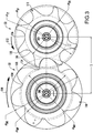
- FIG. 3 a unique lobe configuration is proposed and disclosed in FIG. 3 .
- the male rotor 52 is rotated in a direction 510 about its axis 500 to, in turn, drive the female rotor 54 in an opposite direction 512 about its axis 502.
- this illustrated configuration has seven lobes 110 on the male rotor and eight lobes 112 on the female rotor.
- Each of the respective male and female lobes has a tip 130, 132 and a root 134, 136.
- FIG. 3 shows tip diameters ⁇ MT and ⁇ FT and root diameters ⁇ MR and ⁇ FR .
- FIG. 3 further shows an inter-axis spacing S.
- FIG. 3 also shows pitch diameters ⁇ MP and ⁇ FP . These are defined as an imaginary diameter where pure rolling occurs.
- rotor dimensions are as follows: Table I Rotor Dimensions Dimension Example 1 Prior Art 1 Prior Art 2 Prior Art 3 Male Lobes 7 5 5 5 5 Female lobes 8 7 6 6 ⁇ MT 167.771 ⁇ MR 118.562 ⁇ MT / ⁇ MR 1.415 1.589 1.626 1.451 ⁇ MP 124.936 ⁇ FT 149.158 ⁇ FR 99.949 ⁇ FT / ⁇ FR 1.492 1.755 1.800 1.612 ⁇ FP 142.784 S 133.86
- the tip to root ratio of the male rotor is 1.415 and that of the female rotor is 1.492.
- the exemplary increase of two lobes per rotor may have one or more of several advantages. First, this may be used to reduce the amount of refrigerant compressed in each compression pocket. Thereby, the mass flow per discharge pulse is decreased and the magnitude of the discharge pulse is decreased. This may reduce sound and stimulus for vibration of other system components.
- the relatively low tip-to root ratio may alter the resonance characteristics of the rotors.
- the shallower lobes may increase the rotor dynamic limit.
- the rotor may be relatively stiff and may increase resonance frequencies.
- lower tip-to-root ratio means a greater root diameter and a stiffer lobed working portion of the rotor.
- the increased stiffness of the working portion increases overall stiffness. This is particularly relevant to the male rotor where the motor stator is cantilevered on the rotor shaft portion 62. Resonance excursions of the motor rotor and shaft portion 62 may damage the compressor.
- One solution presenting additional complexities would be to add a bearing at the end of the shaft portion 62.
- the baseline compressor may be kept below 90Hz in order to limit sound and/or limit vibration of the motor rotor.
- the higher lobe count may allow higher speed operation due to both mechanisms mentioned above.
- Exemplary speed is 90Hz to 150Hz, more particularly, exemplary values are 90Hz to 120Hz or 95Hz to 120Hz or 95 Hz to 110Hz or 100Hz to 120Hz.
- exemplary male rotor tip to root ratio is no more than 1.44:1, 1.43:1, or 1.42:1 and exemplary female rotor tip to root ratio is no more than 1.55:1 or 1.50:1. Both of these may be at least 1.1:1 or 1.2:1. More specifically, exemplary male rotor tip to ratio is 1.36:1 to 1.42:1 or 1.41:1 to 1.42:1 and exemplary female rotor tip to ratio is 1.30:1 to 1.50:1 or 1.49:1 to 1.50:1.
- exemplary combined lobe count is fifteen to twenty-one or fifteen to eighteen. This provides the vibration benefits while maintaining sufficient capacity.
- FIG. 1 further shows a controller 200.
- the controller may receive user inputs from an input device (e.g., switches, keyboard, or the like) and sensors (not shown, e.g., pressure sensors and temperature sensors at various system locations).
- the controller may be coupled to the sensors and controllable system components (e.g., valves, the bearings, the compressor motor, vane actuators, and the like) via control lines (e.g., hardwired or wireless communication paths).
- the controller may include one or more: processors; memory (e.g., for storing program information for execution by the processor to perform the operational methods and for storing data used or generated by the program(s)); and hardware interface devices (e.g., ports) for interfacing with input/output devices and controllable system components.
- the controller 200 may control the motor via a variable frequency drive 202 which draws power from a source 204.
- a source 204 is two-phase or three-phase commercial AC wall power as may be available in particular regions of the world. Examples include 240V/60Hz, 460/60, 400/50, 380/50, 575/60, and the like.
- first, second, and the like in the description and following claims is for differentiation within the claim only and does not necessarily indicate relative or absolute importance or temporal order. Similarly, the identification in a claim of one element as “first” (or the like) does not preclude such "first” element from identifying an element that is referred to as “second” (or the like) in another claim or in the description.
Landscapes
- Engineering & Computer Science (AREA)
- Mechanical Engineering (AREA)
- General Engineering & Computer Science (AREA)
- Applications Or Details Of Rotary Compressors (AREA)
- Physics & Mathematics (AREA)
- Thermal Sciences (AREA)
Claims (7)
- Verdichter (22) umfassend:ein Gehäuse (50), das einen ersten Anschluss (26) und einen zweiten Anschluss (28) aufweist;einen männlichen Rotor (52), der Folgendes aufweist:einen Arbeitsbereich (64), der eine Vielzahl von Flügeln (110) von einer Anzahl (NM) aufweist; undmindestens einen ersten Wellenbereich (62), der über ein erstes Ende (68) des Arbeitsbereichs des männlichen Rotors hervorsteht und zur Rotation um eine erste Achse (500) montiert ist;einen weiblichen Rotor (54), der Folgendes aufweist:
einen Arbeitsbereich (66), der eine Vielzahl von Flügeln (112) von einer Anzahl (NF) aufweist und zur Rotation um eine zweite Achse (502) montiert ist, um mit dem Arbeitsbereich des männlichen Rotors verzahnt zu sein; undeinen Elektromotor (56) innerhalb des Gehäuses, der Folgendes aufweist:einen Stator (58); undeinen Rotor (60), der auf dem ersten Wellenbereich montiert ist,dadurch gekennzeichnet, dassdie Flügelanzahl des männlichen Rotors sieben beträgt und die Flügelanzahl des weiblichen Rotors acht beträgt;das Verhältnis Spitze zu Fuß der Flügel des weiblichen Rotors 1,49:1 bis 1,50:1 ist; unddas Verhältnis Spitze zu Fuß der Flügel des männlichen Rotors 1,41:1 bis 1,42:1 ist. - Verdichter nach Anspruch 1, wobei:
der Verdichter keine zusätzlichen Verdichterrotoren aufweist. - Verdichter nach Anspruch 1, wobei:
ein Volllastvolumen-Index 1,7-4,0 beträgt. - Verdichter nach Anspruch 1, wobei:
der erste Wellenbereich (62) von einem Lager (90) zwischen dem ersten Wellenbereich und dem Arbeitsbereich (64) des männlichen Rotors ausgekragt ist. - Verfahren zum Verwenden des Verdichters nach Anspruch 1, wobei:das Laufenlassen des Verdichters Kältemittel verdichtet;das verdichtete Kältemittel zum Kühlen an einen Wärmeabgabe-Wärmetauscher geleitet wird;das gekühlte Kältemittel zum Expandieren und weiteren Kühlen an eine Expansionseinrichtung geleitet wird;das expandierte und weiter gekühlte Kältemittel zum Absorbieren von Hitze und Erwärmen an einen wärmeabsorbierenden Wärmetauscher geleitet wird; unddas erwärmte Kältemittel an den Verdichter zurückgeleitet wird.
- Verfahren nach Anspruch 5, wobei:
das Laufenlassen des Verdichters ein Betreiben bei einem Volumenindex von 1,7-4,0 umfasst. - Dampfverdichtungssystem (20) umfassend:einen Verdichter (22) nach Anspruch 1;einen Wärmeabgabe-Wärmetauscher (30);eine Expansionseinrichtung (32);einen wärmeabsorbierenden Wärmetauscher (34); undeinen Kältemittel-Strömungsweg (24), der sequenziell durch den Verdichter, den Wärmeabgabe-Wärmetauscher, die Expansionseinrichtung und den wärmeabsorbierenden Wärmetauscher verläuft und zum Verdichter zurückgeleitet wird.
Applications Claiming Priority (2)
| Application Number | Priority Date | Filing Date | Title |
|---|---|---|---|
| US201462006487P | 2014-06-02 | 2014-06-02 | |
| PCT/US2015/033526 WO2015187553A1 (en) | 2014-06-02 | 2015-06-01 | Screw compressor |
Publications (2)
| Publication Number | Publication Date |
|---|---|
| EP3149335A1 EP3149335A1 (de) | 2017-04-05 |
| EP3149335B1 true EP3149335B1 (de) | 2020-06-24 |
Family
ID=53373666
Family Applications (1)
| Application Number | Title | Priority Date | Filing Date |
|---|---|---|---|
| EP15728361.5A Active EP3149335B1 (de) | 2014-06-02 | 2015-06-01 | Schraubenverdichter |
Country Status (5)
| Country | Link |
|---|---|
| US (1) | US10436196B2 (de) |
| EP (1) | EP3149335B1 (de) |
| CN (1) | CN106232991B (de) |
| ES (1) | ES2813404T3 (de) |
| WO (1) | WO2015187553A1 (de) |
Family Cites Families (32)
| Publication number | Priority date | Publication date | Assignee | Title |
|---|---|---|---|---|
| DE1936275A1 (de) * | 1969-07-17 | 1971-01-28 | Alois Riedl | Schraubenverdichter mit Schmalkopfprofilen und Kreisbogenhobelflanken |
| US3986801A (en) | 1975-05-06 | 1976-10-19 | Frick Company | Screw compressor |
| GB1548663A (en) * | 1975-06-24 | 1979-07-18 | Maekawa Seisakusho Kk | Refrigerating apparatus |
| US4643654A (en) | 1985-09-12 | 1987-02-17 | American Standard Inc. | Screw rotor profile and method for generating |
| US5108275A (en) | 1990-12-17 | 1992-04-28 | Sager William F | Rotary pump having helical gear teeth with a small angle of wrap |
| JPH07293468A (ja) | 1994-04-28 | 1995-11-07 | Toshiba Corp | 密閉形コンプレッサ |
| US5642992A (en) | 1995-10-30 | 1997-07-01 | Shaw; David N. | Multi-rotor helical screw compressor |
| GB9610289D0 (en) | 1996-05-16 | 1996-07-24 | Univ City | Plural screw positive displacement machines |
| US6003324A (en) | 1997-07-11 | 1999-12-21 | Shaw; David N. | Multi-rotor helical screw compressor with unloading |
| AU2002952005A0 (en) | 2002-10-11 | 2002-10-31 | Hudson, Barry | A rotary engine |
| JP4147891B2 (ja) * | 2002-10-16 | 2008-09-10 | ダイキン工業株式会社 | 可変vi式インバータスクリュー圧縮機 |
| DE10258145A1 (de) * | 2002-12-03 | 2004-06-24 | Bitzer Kühlmaschinenbau Gmbh | Schraubenverdichter |
| US7163387B2 (en) | 2002-12-16 | 2007-01-16 | Carrier Corporation | Meshing helical rotors |
| US7121814B2 (en) | 2004-09-30 | 2006-10-17 | Carrier Corporation | Compressor sound suppression |
| JP4914134B2 (ja) * | 2005-07-12 | 2012-04-11 | キヤノン株式会社 | 被記録媒体及び該被記録媒体を用いた画像形成方法 |
| JP4650180B2 (ja) | 2005-09-22 | 2011-03-16 | アイシン精機株式会社 | オイルポンプロータ |
| JP2008115747A (ja) * | 2006-11-02 | 2008-05-22 | Toyota Industries Corp | 電動ポンプ |
| JP2011510257A (ja) | 2008-01-17 | 2011-03-31 | キャリア コーポレイション | 冷媒蒸気圧縮システムの容量調整 |
| US7980836B2 (en) | 2008-06-06 | 2011-07-19 | Shaw David N | Modular multi-rotor compressor and method of manufacture |
| US20100024736A1 (en) * | 2008-08-01 | 2010-02-04 | Paul Davis | Food house for small animals |
| KR101268612B1 (ko) | 2008-11-17 | 2013-05-29 | 엘지전자 주식회사 | 주파수 가변 압축기 및 그 제어 방법 |
| JP2010223145A (ja) | 2009-03-25 | 2010-10-07 | Hitachi Appliances Inc | スクリュー圧縮機 |
| US8089207B2 (en) * | 2010-05-10 | 2012-01-03 | Abl Ip Holding Llc | Lighting using solid state device and phosphors to produce light approximating a black body radiation spectrum |
| US9151292B2 (en) | 2011-01-05 | 2015-10-06 | Hi-Bar Blowers, Inc. | Screw compressor with a shunt pulsation trap |
| JP5795726B2 (ja) | 2011-06-27 | 2015-10-14 | 株式会社山田製作所 | オイルポンプ |
| CN102287374B (zh) | 2011-09-07 | 2013-10-16 | 中国船舶重工集团公司第七一一研究所 | 一种双螺杆压缩机转子的齿型 |
| CN102352840B (zh) * | 2011-09-29 | 2013-08-28 | 陕西丰赜机电科技有限公司 | 螺杆转子端面廓形副及其构造方法 |
| US9032750B2 (en) * | 2011-10-18 | 2015-05-19 | Johnson Controls Technology Company | Manual Vi adjustment mechanism for screw compressors |
| US9022760B2 (en) | 2011-11-02 | 2015-05-05 | Trane International Inc. | High pressure seal vent |
| CN202971199U (zh) * | 2012-12-18 | 2013-06-05 | 中国石油集团济柴动力总厂成都压缩机厂 | 一种适用于双螺杆压缩机的转子型线结构 |
| CN103603805A (zh) | 2013-11-21 | 2014-02-26 | 南京压缩机股份有限公司 | 双螺杆压缩机转子型线 |
| US20160208801A1 (en) * | 2015-01-20 | 2016-07-21 | Ingersoll-Rand Company | High Pressure, Single Stage Rotor |
-
2015
- 2015-06-01 EP EP15728361.5A patent/EP3149335B1/de active Active
- 2015-06-01 ES ES15728361T patent/ES2813404T3/es active Active
- 2015-06-01 US US15/315,551 patent/US10436196B2/en active Active
- 2015-06-01 WO PCT/US2015/033526 patent/WO2015187553A1/en not_active Ceased
- 2015-06-01 CN CN201580021068.0A patent/CN106232991B/zh active Active
Non-Patent Citations (1)
| Title |
|---|
| None * |
Also Published As
| Publication number | Publication date |
|---|---|
| EP3149335A1 (de) | 2017-04-05 |
| CN106232991B (zh) | 2018-11-09 |
| US10436196B2 (en) | 2019-10-08 |
| US20170122318A1 (en) | 2017-05-04 |
| ES2813404T3 (es) | 2021-03-23 |
| CN106232991A (zh) | 2016-12-14 |
| WO2015187553A1 (en) | 2015-12-10 |
Similar Documents
| Publication | Publication Date | Title |
|---|---|---|
| CN106368946B (zh) | 喷气增焓涡旋压缩机及空调系统 | |
| US10309700B2 (en) | High pressure compressor and refrigerating machine having a high pressure compressor | |
| CN104471251A (zh) | 气体压缩机 | |
| EP3546754B1 (de) | Enthalpie-erhöhender luftinjektionsspiralverdichter und kühlsystem | |
| CN106715913B (zh) | 旋转式压缩机及冷冻循环装置 | |
| JP5228905B2 (ja) | 冷凍装置 | |
| US20130136626A1 (en) | Screw compressor with muffle structure and rotor seat thereof | |
| CN109578274A (zh) | 一种涡盘、包含该涡盘的压缩机构及涡旋压缩机 | |
| US2904973A (en) | Variable displacement rotary compressor | |
| EP3149335B1 (de) | Schraubenverdichter | |
| JP2010156244A (ja) | 圧縮機および冷凍装置 | |
| JPH11241693A (ja) | 圧縮機 | |
| CN209943112U (zh) | 一种涡旋压缩机的补气结构及涡旋压缩机 | |
| US10619635B2 (en) | Scallop step for a scroll compressor | |
| CN205064273U (zh) | 滚动转子式压缩机 | |
| CN103216442B (zh) | 涡旋压缩机 | |
| CN202326243U (zh) | 双级增焓压缩机及具有其的空调器和热泵热水器 | |
| CN210033831U (zh) | 泵体组件及压缩机 | |
| CN106468260B (zh) | 涡旋压缩机和空调系统 | |
| US12098722B2 (en) | Method for determining a discharge pressure of a rolling piston compressor | |
| JPH0712708Y2 (ja) | 密閉形電動圧縮機 | |
| JP2000009065A (ja) | スクロール型圧縮機 | |
| JPH01318787A (ja) | 低圧式ロータリ圧縮機 | |
| JPH0113823Y2 (de) | ||
| JPH0350397A (ja) | 回転式圧縮機 |
Legal Events
| Date | Code | Title | Description |
|---|---|---|---|
| STAA | Information on the status of an ep patent application or granted ep patent |
Free format text: STATUS: THE INTERNATIONAL PUBLICATION HAS BEEN MADE |
|
| PUAI | Public reference made under article 153(3) epc to a published international application that has entered the european phase |
Free format text: ORIGINAL CODE: 0009012 |
|
| STAA | Information on the status of an ep patent application or granted ep patent |
Free format text: STATUS: REQUEST FOR EXAMINATION WAS MADE |
|
| 17P | Request for examination filed |
Effective date: 20161018 |
|
| AK | Designated contracting states |
Kind code of ref document: A1 Designated state(s): AL AT BE BG CH CY CZ DE DK EE ES FI FR GB GR HR HU IE IS IT LI LT LU LV MC MK MT NL NO PL PT RO RS SE SI SK SM TR |
|
| AX | Request for extension of the european patent |
Extension state: BA ME |
|
| DAV | Request for validation of the european patent (deleted) | ||
| DAX | Request for extension of the european patent (deleted) | ||
| GRAP | Despatch of communication of intention to grant a patent |
Free format text: ORIGINAL CODE: EPIDOSNIGR1 |
|
| STAA | Information on the status of an ep patent application or granted ep patent |
Free format text: STATUS: GRANT OF PATENT IS INTENDED |
|
| INTG | Intention to grant announced |
Effective date: 20200309 |
|
| GRAS | Grant fee paid |
Free format text: ORIGINAL CODE: EPIDOSNIGR3 |
|
| GRAA | (expected) grant |
Free format text: ORIGINAL CODE: 0009210 |
|
| STAA | Information on the status of an ep patent application or granted ep patent |
Free format text: STATUS: THE PATENT HAS BEEN GRANTED |
|
| AK | Designated contracting states |
Kind code of ref document: B1 Designated state(s): AL AT BE BG CH CY CZ DE DK EE ES FI FR GB GR HR HU IE IS IT LI LT LU LV MC MK MT NL NO PL PT RO RS SE SI SK SM TR |
|
| REG | Reference to a national code |
Ref country code: GB Ref legal event code: FG4D |
|
| REG | Reference to a national code |
Ref country code: CH Ref legal event code: EP |
|
| REG | Reference to a national code |
Ref country code: AT Ref legal event code: REF Ref document number: 1284150 Country of ref document: AT Kind code of ref document: T Effective date: 20200715 |
|
| REG | Reference to a national code |
Ref country code: DE Ref legal event code: R096 Ref document number: 602015054693 Country of ref document: DE |
|
| REG | Reference to a national code |
Ref country code: IE Ref legal event code: FG4D |
|
| REG | Reference to a national code |
Ref country code: NL Ref legal event code: FP |
|
| PG25 | Lapsed in a contracting state [announced via postgrant information from national office to epo] |
Ref country code: FI Free format text: LAPSE BECAUSE OF FAILURE TO SUBMIT A TRANSLATION OF THE DESCRIPTION OR TO PAY THE FEE WITHIN THE PRESCRIBED TIME-LIMIT Effective date: 20200624 Ref country code: SE Free format text: LAPSE BECAUSE OF FAILURE TO SUBMIT A TRANSLATION OF THE DESCRIPTION OR TO PAY THE FEE WITHIN THE PRESCRIBED TIME-LIMIT Effective date: 20200624 Ref country code: LT Free format text: LAPSE BECAUSE OF FAILURE TO SUBMIT A TRANSLATION OF THE DESCRIPTION OR TO PAY THE FEE WITHIN THE PRESCRIBED TIME-LIMIT Effective date: 20200624 Ref country code: GR Free format text: LAPSE BECAUSE OF FAILURE TO SUBMIT A TRANSLATION OF THE DESCRIPTION OR TO PAY THE FEE WITHIN THE PRESCRIBED TIME-LIMIT Effective date: 20200925 Ref country code: NO Free format text: LAPSE BECAUSE OF FAILURE TO SUBMIT A TRANSLATION OF THE DESCRIPTION OR TO PAY THE FEE WITHIN THE PRESCRIBED TIME-LIMIT Effective date: 20200924 |
|
| REG | Reference to a national code |
Ref country code: LT Ref legal event code: MG4D |
|
| PG25 | Lapsed in a contracting state [announced via postgrant information from national office to epo] |
Ref country code: BG Free format text: LAPSE BECAUSE OF FAILURE TO SUBMIT A TRANSLATION OF THE DESCRIPTION OR TO PAY THE FEE WITHIN THE PRESCRIBED TIME-LIMIT Effective date: 20200924 Ref country code: RS Free format text: LAPSE BECAUSE OF FAILURE TO SUBMIT A TRANSLATION OF THE DESCRIPTION OR TO PAY THE FEE WITHIN THE PRESCRIBED TIME-LIMIT Effective date: 20200624 Ref country code: LV Free format text: LAPSE BECAUSE OF FAILURE TO SUBMIT A TRANSLATION OF THE DESCRIPTION OR TO PAY THE FEE WITHIN THE PRESCRIBED TIME-LIMIT Effective date: 20200624 Ref country code: HR Free format text: LAPSE BECAUSE OF FAILURE TO SUBMIT A TRANSLATION OF THE DESCRIPTION OR TO PAY THE FEE WITHIN THE PRESCRIBED TIME-LIMIT Effective date: 20200624 |
|
| REG | Reference to a national code |
Ref country code: AT Ref legal event code: MK05 Ref document number: 1284150 Country of ref document: AT Kind code of ref document: T Effective date: 20200624 |
|
| PG25 | Lapsed in a contracting state [announced via postgrant information from national office to epo] |
Ref country code: AL Free format text: LAPSE BECAUSE OF FAILURE TO SUBMIT A TRANSLATION OF THE DESCRIPTION OR TO PAY THE FEE WITHIN THE PRESCRIBED TIME-LIMIT Effective date: 20200624 |
|
| PG25 | Lapsed in a contracting state [announced via postgrant information from national office to epo] |
Ref country code: AT Free format text: LAPSE BECAUSE OF FAILURE TO SUBMIT A TRANSLATION OF THE DESCRIPTION OR TO PAY THE FEE WITHIN THE PRESCRIBED TIME-LIMIT Effective date: 20200624 Ref country code: SM Free format text: LAPSE BECAUSE OF FAILURE TO SUBMIT A TRANSLATION OF THE DESCRIPTION OR TO PAY THE FEE WITHIN THE PRESCRIBED TIME-LIMIT Effective date: 20200624 Ref country code: EE Free format text: LAPSE BECAUSE OF FAILURE TO SUBMIT A TRANSLATION OF THE DESCRIPTION OR TO PAY THE FEE WITHIN THE PRESCRIBED TIME-LIMIT Effective date: 20200624 Ref country code: RO Free format text: LAPSE BECAUSE OF FAILURE TO SUBMIT A TRANSLATION OF THE DESCRIPTION OR TO PAY THE FEE WITHIN THE PRESCRIBED TIME-LIMIT Effective date: 20200624 Ref country code: IT Free format text: LAPSE BECAUSE OF FAILURE TO SUBMIT A TRANSLATION OF THE DESCRIPTION OR TO PAY THE FEE WITHIN THE PRESCRIBED TIME-LIMIT Effective date: 20200624 Ref country code: CZ Free format text: LAPSE BECAUSE OF FAILURE TO SUBMIT A TRANSLATION OF THE DESCRIPTION OR TO PAY THE FEE WITHIN THE PRESCRIBED TIME-LIMIT Effective date: 20200624 Ref country code: PT Free format text: LAPSE BECAUSE OF FAILURE TO SUBMIT A TRANSLATION OF THE DESCRIPTION OR TO PAY THE FEE WITHIN THE PRESCRIBED TIME-LIMIT Effective date: 20201026 |
|
| PG25 | Lapsed in a contracting state [announced via postgrant information from national office to epo] |
Ref country code: PL Free format text: LAPSE BECAUSE OF FAILURE TO SUBMIT A TRANSLATION OF THE DESCRIPTION OR TO PAY THE FEE WITHIN THE PRESCRIBED TIME-LIMIT Effective date: 20200624 Ref country code: SK Free format text: LAPSE BECAUSE OF FAILURE TO SUBMIT A TRANSLATION OF THE DESCRIPTION OR TO PAY THE FEE WITHIN THE PRESCRIBED TIME-LIMIT Effective date: 20200624 Ref country code: IS Free format text: LAPSE BECAUSE OF FAILURE TO SUBMIT A TRANSLATION OF THE DESCRIPTION OR TO PAY THE FEE WITHIN THE PRESCRIBED TIME-LIMIT Effective date: 20201024 |
|
| REG | Reference to a national code |
Ref country code: ES Ref legal event code: FG2A Ref document number: 2813404 Country of ref document: ES Kind code of ref document: T3 Effective date: 20210323 |
|
| REG | Reference to a national code |
Ref country code: DE Ref legal event code: R097 Ref document number: 602015054693 Country of ref document: DE |
|
| PG25 | Lapsed in a contracting state [announced via postgrant information from national office to epo] |
Ref country code: DK Free format text: LAPSE BECAUSE OF FAILURE TO SUBMIT A TRANSLATION OF THE DESCRIPTION OR TO PAY THE FEE WITHIN THE PRESCRIBED TIME-LIMIT Effective date: 20200624 |
|
| PLBE | No opposition filed within time limit |
Free format text: ORIGINAL CODE: 0009261 |
|
| STAA | Information on the status of an ep patent application or granted ep patent |
Free format text: STATUS: NO OPPOSITION FILED WITHIN TIME LIMIT |
|
| 26N | No opposition filed |
Effective date: 20210325 |
|
| PG25 | Lapsed in a contracting state [announced via postgrant information from national office to epo] |
Ref country code: SI Free format text: LAPSE BECAUSE OF FAILURE TO SUBMIT A TRANSLATION OF THE DESCRIPTION OR TO PAY THE FEE WITHIN THE PRESCRIBED TIME-LIMIT Effective date: 20200624 |
|
| PG25 | Lapsed in a contracting state [announced via postgrant information from national office to epo] |
Ref country code: MC Free format text: LAPSE BECAUSE OF FAILURE TO SUBMIT A TRANSLATION OF THE DESCRIPTION OR TO PAY THE FEE WITHIN THE PRESCRIBED TIME-LIMIT Effective date: 20200624 |
|
| REG | Reference to a national code |
Ref country code: CH Ref legal event code: PL |
|
| REG | Reference to a national code |
Ref country code: BE Ref legal event code: MM Effective date: 20210630 |
|
| PG25 | Lapsed in a contracting state [announced via postgrant information from national office to epo] |
Ref country code: LU Free format text: LAPSE BECAUSE OF NON-PAYMENT OF DUE FEES Effective date: 20210601 |
|
| PG25 | Lapsed in a contracting state [announced via postgrant information from national office to epo] |
Ref country code: LI Free format text: LAPSE BECAUSE OF NON-PAYMENT OF DUE FEES Effective date: 20210630 Ref country code: IE Free format text: LAPSE BECAUSE OF NON-PAYMENT OF DUE FEES Effective date: 20210601 Ref country code: CH Free format text: LAPSE BECAUSE OF NON-PAYMENT OF DUE FEES Effective date: 20210630 |
|
| PGFP | Annual fee paid to national office [announced via postgrant information from national office to epo] |
Ref country code: NL Payment date: 20220523 Year of fee payment: 8 |
|
| PG25 | Lapsed in a contracting state [announced via postgrant information from national office to epo] |
Ref country code: BE Free format text: LAPSE BECAUSE OF NON-PAYMENT OF DUE FEES Effective date: 20210630 |
|
| PG25 | Lapsed in a contracting state [announced via postgrant information from national office to epo] |
Ref country code: HU Free format text: LAPSE BECAUSE OF FAILURE TO SUBMIT A TRANSLATION OF THE DESCRIPTION OR TO PAY THE FEE WITHIN THE PRESCRIBED TIME-LIMIT; INVALID AB INITIO Effective date: 20150601 |
|
| PG25 | Lapsed in a contracting state [announced via postgrant information from national office to epo] |
Ref country code: CY Free format text: LAPSE BECAUSE OF FAILURE TO SUBMIT A TRANSLATION OF THE DESCRIPTION OR TO PAY THE FEE WITHIN THE PRESCRIBED TIME-LIMIT Effective date: 20200624 |
|
| P01 | Opt-out of the competence of the unified patent court (upc) registered |
Effective date: 20230527 |
|
| REG | Reference to a national code |
Ref country code: NL Ref legal event code: MM Effective date: 20230701 |
|
| PG25 | Lapsed in a contracting state [announced via postgrant information from national office to epo] |
Ref country code: NL Free format text: LAPSE BECAUSE OF NON-PAYMENT OF DUE FEES Effective date: 20230701 |
|
| PG25 | Lapsed in a contracting state [announced via postgrant information from national office to epo] |
Ref country code: MK Free format text: LAPSE BECAUSE OF FAILURE TO SUBMIT A TRANSLATION OF THE DESCRIPTION OR TO PAY THE FEE WITHIN THE PRESCRIBED TIME-LIMIT Effective date: 20200624 |
|
| PG25 | Lapsed in a contracting state [announced via postgrant information from national office to epo] |
Ref country code: MT Free format text: LAPSE BECAUSE OF FAILURE TO SUBMIT A TRANSLATION OF THE DESCRIPTION OR TO PAY THE FEE WITHIN THE PRESCRIBED TIME-LIMIT Effective date: 20200624 |
|
| PGFP | Annual fee paid to national office [announced via postgrant information from national office to epo] |
Ref country code: ES Payment date: 20240701 Year of fee payment: 10 |
|
| PGFP | Annual fee paid to national office [announced via postgrant information from national office to epo] |
Ref country code: DE Payment date: 20250520 Year of fee payment: 11 |
|
| PGFP | Annual fee paid to national office [announced via postgrant information from national office to epo] |
Ref country code: GB Payment date: 20250520 Year of fee payment: 11 |
|
| PGFP | Annual fee paid to national office [announced via postgrant information from national office to epo] |
Ref country code: FR Payment date: 20250520 Year of fee payment: 11 |
|
| PG25 | Lapsed in a contracting state [announced via postgrant information from national office to epo] |
Ref country code: TR Free format text: LAPSE BECAUSE OF FAILURE TO SUBMIT A TRANSLATION OF THE DESCRIPTION OR TO PAY THE FEE WITHIN THE PRESCRIBED TIME-LIMIT Effective date: 20200624 |