EP3149291B1 - Nockenwelle mit verschlussdeckel - Google Patents
Nockenwelle mit verschlussdeckel Download PDFInfo
- Publication number
- EP3149291B1 EP3149291B1 EP15725504.3A EP15725504A EP3149291B1 EP 3149291 B1 EP3149291 B1 EP 3149291B1 EP 15725504 A EP15725504 A EP 15725504A EP 3149291 B1 EP3149291 B1 EP 3149291B1
- Authority
- EP
- European Patent Office
- Prior art keywords
- camshaft
- indentations
- hollow shaft
- closing cover
- holding means
- Prior art date
- Legal status (The legal status is an assumption and is not a legal conclusion. Google has not performed a legal analysis and makes no representation as to the accuracy of the status listed.)
- Active
Links
Images


Classifications
-
- F—MECHANICAL ENGINEERING; LIGHTING; HEATING; WEAPONS; BLASTING
- F01—MACHINES OR ENGINES IN GENERAL; ENGINE PLANTS IN GENERAL; STEAM ENGINES
- F01L—CYCLICALLY OPERATING VALVES FOR MACHINES OR ENGINES
- F01L1/00—Valve-gear or valve arrangements, e.g. lift-valve gear
- F01L1/02—Valve drive
- F01L1/04—Valve drive by means of cams, camshafts, cam discs, eccentrics or the like
- F01L1/047—Camshafts
-
- F—MECHANICAL ENGINEERING; LIGHTING; HEATING; WEAPONS; BLASTING
- F16—ENGINEERING ELEMENTS AND UNITS; GENERAL MEASURES FOR PRODUCING AND MAINTAINING EFFECTIVE FUNCTIONING OF MACHINES OR INSTALLATIONS; THERMAL INSULATION IN GENERAL
- F16H—GEARING
- F16H53/00—Cams or cam-followers, e.g. rollers for gearing mechanisms
- F16H53/02—Single-track cams for single-revolution cycles; Camshafts with such cams
- F16H53/025—Single-track cams for single-revolution cycles; Camshafts with such cams characterised by their construction, e.g. assembling or manufacturing features
-
- F—MECHANICAL ENGINEERING; LIGHTING; HEATING; WEAPONS; BLASTING
- F01—MACHINES OR ENGINES IN GENERAL; ENGINE PLANTS IN GENERAL; STEAM ENGINES
- F01L—CYCLICALLY OPERATING VALVES FOR MACHINES OR ENGINES
- F01L1/00—Valve-gear or valve arrangements, e.g. lift-valve gear
- F01L1/02—Valve drive
- F01L1/04—Valve drive by means of cams, camshafts, cam discs, eccentrics or the like
- F01L1/047—Camshafts
- F01L2001/0475—Hollow camshafts
Definitions
- the invention relates to a camshaft according to the preamble of claim 1 and an assembly method for a camshaft according to the preamble of claims 16 and 19.
- Camshafts can be provided with radial bores through which oil can be conducted.
- a built-in sealing cap inside the camshaft ensures that no oil penetrates into undesired areas. If a locking cap is present, it is important that it does not slip during operation of the camshaft. On the one hand, slipping would change the oil pressure conditions within the camshaft and, on the other hand, supply bores could be clogged or cut off from the oil supply.
- a camshaft comprising a hollow shaft, at least one cam and a closure cover arranged inside the hollow shaft and spaced apart from the cam in the axial direction, the camshaft comprising one or more indentations, is already known from DE 10 2007 019923 A1 known. With this camshaft, too, there is a risk that the sealing caps will slip and the disadvantages outlined above may occur.
- WO 91/19887 describes a device for distributing oil, which enables targeted guidance of multiple oil flows within a camshaft.
- the oil flows are completely separate from each other and can therefore have different pressures, mass flows and directions of flow.
- an axially extending insert is provided within the camshaft.
- the object of the present invention is to modify a camshaft, consisting of a hollow shaft, without great technical effort and as flexibly as possible in such a way that slipping of an installed sealing cover is prevented.
- the object is solved by the characterizing features of claim 1.
- the axial extent of the one or more holding means is smaller than or equal to the axial distance between an end of the closure cap facing the cam and the cam.
- the one or more indentations are holding means which protrude into the interior of the hollow shaft and are firmly mounted with a connecting means.
- the holding means can be one or more holding means introduced through bores from the outside through the outer wall of the camshaft, which protrude into the interior of the hollow shaft, or one or more holding means mounted in the camshaft from the inside.
- the retaining means are secured in the camshaft by means of a fastener.
- the term composite means is to be considered broadly defined.
- the connecting means can involve welding, for example, but it can also involve screwing, gluing or pressing in.
- the one or more indentations can be rotationally symmetrical, or arranged symmetrically or asymmetrically.
- a rotationally symmetrical arrangement is particularly advantageous here, since this does not impair the rotational behavior of the camshaft.
- the invention is preferably further developed in that a camshaft, which comprises a hollow shaft, at least one cam and a closure cap arranged inside the hollow shaft and at a distance from the cam in the axial direction, is provided with one or more indentations in order to prevent the closure cap from slipping in to prevent at least one axial direction.
- the axial extent of the one or more indentations is less than or equal to the axial distance between an end of the closure cover facing the cam and the cam.
- the indentations can be both local deformations of the hollow shaft caused from the outside and holding means mounted in the hollow shaft from the outside or inside, which protrude into the interior of the hollow shaft and thus locally narrow the cross section of the hollow shaft at the corresponding point.
- the one or more indentations have the advantage that they can also only be introduced into the camshaft tube during the assembly process.
- the camshaft comprising a hollow shaft, has one or more supply openings to supply oil to bearings and adjacent devices, such as a brake booster or a phaser.
- Making one or more indentations in the camshaft ensures that the supply openings made in the camshaft cannot be closed during operation due to torsion, oil pressure, or circumferential bending of the camshaft due to the sealing cover slipping. Furthermore, by preventing the cover cap from slipping, the oil pressure within the camshaft is kept constant.
- the one or more indentations protruding into the interior of the camshaft are arranged arbitrarily in one or more planes orthogonal to the axial direction of the camshaft, with at least one indentation being attached in such a way that the closure cap cannot slip onto the nearest supply opening, so that an oil supply through the Supply openings is guaranteed.
- the one or more indentations can be arranged in the axial direction of the camshaft between the closure cap and the supply borehole closest to the closure cap or can be attached to the same axial positioning as the supply borehole closest to the closure cap.
- the one or more indentations can also extend in the axial direction of the camshaft from the end of the closure cap to the supply bore closest to the closure cap or in the axial direction of the camshaft from the end of the closure cap to the axial position of the nearest cam over the intermediate interior of the camshaft, in which the one or more supply bores are located, extend.
- the position of the indentations can be selected as required and according to the desired rotational behavior of the camshaft. It is particularly advantageous to have an indentation radially surrounding the hollow shaft in the same axial position as that of a supply bore, so that the supply bore is located within the circumferential indentation. In this way, the peripheral indentation forms an oil transfer ring or an oil groove, through which a good oil supply or oil transfer can be ensured.
- the closure cap In order to prevent the closure cap from slipping inside the camshaft, it can also be wedged in by having one or more indentations on each side of the closure cap in the axial direction of the camshaft. In this way, the cap cannot move in any direction within the camshaft, which prevents slippage of the cap from affecting the size of the cavity delimited by the cap and thus the oil pressure within the camshaft.
- the one or more indentations are rolled indentations stamped into the camshaft from the outside, plastic indentations, indentations or indentations introduced by means of a stamp.
- Indentations made in the camshaft from the outside have the decisive advantage that no dirt gets into the hollow shaft and thus into the oil circuit during the process for making the indentations.
- the indentations are preferably indentations that run radially around the hollow shaft. Such indentations have the particular advantage that good oil transfer can be guaranteed if they are in an axial position where there is also a supply hole.
- rolling is easy to implement, since no complex tools are required for rolling.
- the object according to the invention is also achieved by an assembly method for a camshaft, comprising a hollow shaft and a closure cover arranged inside the hollow shaft, in which one or more indentations are made in the camshaft after the closure cover has been inserted into the camshaft.
- a camshaft comprising a hollow shaft and a closure cover arranged inside the hollow shaft, in which one or more indentations are made in the camshaft after the closure cover has been inserted into the camshaft.
- the one or more indentations have a defined minimum extent in the radial and axial direction after being introduced into the camshaft and can subsequently be expanded in both directions.
- the width and depth of the indentations can be subsequently expanded as required.
- indentations are rolled into the camshaft from the outside, formed by means of a stamp, notched or pressed in order to prevent the closure cap from slipping in at least one axial direction impede.
- the introduction of indentations from the outside into the camshaft, such as a circumferential groove, does not bring dirt into the hollow shaft and thus into the oil circuit.
- the one or more indentations are introduced into the camshaft from the outside in a rotationally symmetrical manner.
- the rotation properties of the camshaft are retained due to the rotational symmetry of the rolling-in, plastic deformation introduced by means of a stamp, indentation or indentation.
- a constriction extending over at least part of the circumference of the camshaft, preferably completely circumferentially, is introduced. If the hollow shaft is constricted all the way around, a three-roller rolling apparatus with rollers offset by 120°, which can be either driven or non-driven, can be used in the assembly process.
- the Rollers can be adjusted radially so that a specific contour can be traced on the camshaft surface.
- a constriction is rolled into the hollow shaft by the adjustable rollers, the rollers preferably being closed in a controlled manner in such a way that they produce a constriction in the hollow shaft without reducing the wall thickness of the hollow shaft.
- the eccentricity at the constriction in the hollow shaft can also be improved, which is particularly advantageous with regard to using the constriction as an oil transfer or storage point.
- the process time of the assembly process can be reduced, for example by adjusting the rollers radially differently.
- the force acting on the hollow shaft can be better balanced with a three-roller arrangement.
- retaining means are mounted in the camshaft by retaining means being inserted through bores in the hollow shaft, which protrude into the interior of the camshaft.
- melt through a bore would have the disadvantage that the torsional rigidity of the camshaft is reduced by the bore.
- Introducing melt through the end of the hollow shaft would not result in a reduction in torsional rigidity.
- the introduced melt can take various forms. This can be a single spot weld or a weld bead which, for example, extends radially completely around the inside of the hollow shaft.
- retaining means are fitted into the hollow shaft from the inside in order to prevent the closure cap from slipping in at least one axial direction, the retaining means being secured in the hollow shaft by means of a bonding agent are attached.
- holding means are attached by means of composite means inside the camshaft, the cap is through the Holding means prevented from slipping and at the same time the surface of the outer wall of the camshaft does not change in shape.
- the holding means are fastened inside the camshaft by means of gluing, screwing or welding.
- the advantage of the invention is that it is possible to insert the one or more indentations, which prevent the closure cover from slipping in the camshaft, into the camshaft tube only during the assembly process. In this way, supply bores, sealing caps and associated indentations, which prevent the one or more sealing caps from slipping into undesired positions, can be built into the camshaft in a flexible manner.
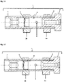
- camshaft 1 shows a camshaft 1 consisting of a hollow shaft 2, which is occupied by cams 3a and 3b and is closed with an end piece 4, which is provided with an annular seal 5.
- the camshaft 1 is provided with a supply port 6 through which oil is supplied to adjacent bearings and devices.
- a sealing cover 7 in the camshaft.
- the sealing cover 7 was pressed under a cam 3b and thus constricted in the hollow shaft 2 .
- the closure cover 7 is spaced axially from the cam 3a.
- the Indentation 8 in the form of a roll is rotationally symmetrical and is located in the same axial position as the supply hole 6. This narrows the cross section of the hollow shaft locally at the corresponding point.
- the axial extension of the indentation 8 is smaller than the axial distance between an end of the closure cover 7 facing the cam 3a and the cam 3a.
- FIG. 2 shows a camshaft 1, which is constructed similarly to that shown in 1 is shown.
- the device sketches 1 and 2 differ in that the indentation 8 , which in this example corresponds to a rotationally symmetrical indentation, is located between the end of the closure cap and the supply opening 6 .
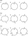
- FIG. 3 shows three examples of cross-sections of camshafts 1 comprising a hollow shaft 2 at the axial position where an indentation 8 is located.
- the indentation can be a plastic indentation that is produced by means of a stamp, an indentation or an indentation.
- Figure 3a shows an indentation in the form of a single stamped indentation
- Figure 3b shows an indentation in the form of a single indentation
- 3c shows an indentation in the form of a single indentation.
- FIG. 4 shows three examples of cross sections of camshafts 1, comprising a hollow shaft 2, at the axial position where a mirror-symmetrical indentation 8 is located.
- the indentation can be a plastic indentation that is produced by means of a stamp, an indentation or an indentation.
- Figure 4a shows an indentation in the form of two opposing stamped indentations
- Figure 4b shows an indentation in the form of two opposing indentations
- Figure 4c shows an indentation in the form of two opposite indentations.
- FIG. 1 shows three examples of cross-sections of camshafts 1 comprising a hollow shaft 2 at the axial position where an asymmetric indentation 8 is located.
- the indentation can be a plastic indentation that is produced by means of a stamp, an indentation or an indentation.
- Figure 5a shows an indentation in the form of three stamped indentations
- Figure 5b shows an indentation in the form of three indentations
- Figure 5c shows an indentation in the form of three indentations.
- 6 shows three examples of cross sections of camshafts, comprising a hollow shaft 2, at the axial position at which an indentation 8 in the form of a single indentation extends from the inside into the hollow shaft 2 mounted holding means 9 is located.
- 6a) to 6c ) show exemplary shapes for a holding means mounted inside the hollow shaft.
- FIG. 7 shows three examples of cross-sections of camshafts, comprising a hollow shaft 2, at the axial position at which there is a mirror-symmetrical indentation 8 in the form of two opposing holding means 9, which are mounted in the hollow shaft 2 from the inside.
- 7a) to 7c ) show exemplary shapes for a holding means mounted inside the hollow shaft.
- FIG. 8 shows three examples of cross-sections of camshafts 1, comprising a hollow shaft 2, at the axial position where there is an asymmetric indentation 8 in the form of three holding means 9 mounted in the hollow shaft 2 from the inside.
- 8a) to 8c ) show exemplary shapes for a holding means mounted inside the hollow shaft.
- the holding means 9 shows the cross section of a camshaft 1 in an axial position, at which a holding means 9 is introduced from the outside through a bore 10 in the camshaft wall, which protrudes into the interior of the camshaft 1.
- the holding means 9 is a solid cylinder.
- the presented form of the holding means is only an example.
- the holding means 9 is a hollowed-out cylinder that serves as a supply opening 6 .
- the presented form of the holding means is only an example.
- FIG. 11 shows a camshaft 1 consisting of a hollow shaft 2, which is occupied by cams 3a and 3b and is closed with an end piece 4, which is provided with an annular seal 5.
- the camshaft 1 is provided with a supply port 6 through which oil is supplied to adjacent bearings and devices.
- a sealing cover 7 in the camshaft.
- the sealing cover 7 was pressed under a cam 3b and thus constricted in the hollow shaft 2 .
- the closure cover 7 is spaced axially from the cam 3a.
- the accumulation of material is introduced from the end of the hollow shaft
- the axial extent of the indentation 9 is smaller than the axial distance between an end of the closure cap 7 facing the cam 3a and the cam 3a.
- FIG. 12 shows a camshaft 1 consisting of a hollow shaft 2, which is occupied by cams 3a and 3b and is closed with an end piece 4, which is provided with an annular seal 5.
- the camshaft 1 is provided with a supply port 6 through which oil is supplied to adjacent bearings and devices.
- a sealing cover 7 in the camshaft.
- the sealing cover 7 was pressed under a cam 3b and thus constricted in the hollow shaft 2 .
- the closure cover 7 is spaced axially from the cam 3a.
- the accumulation of material has been introduced from the end of the hollow shaft and is located in the axial direction between the closure cover 7 and the supply opening 6 closest to the closure cover, just next to the closure cover 7.
- the axial extent of the indentation 9 is smaller than the axial distance between one of the Cam 3a facing the end of the closure cover 7 and the cam 3a.
Landscapes
- Engineering & Computer Science (AREA)
- General Engineering & Computer Science (AREA)
- Mechanical Engineering (AREA)
- Valve-Gear Or Valve Arrangements (AREA)
Description
- Die Erfindung betrifft eine Nockenwelle gemäß dem Oberbegriff des Anspruchs 1, sowie ein Montageverfahren für eine Nockenwelle gemäß dem Oberbegriff des Anspruchs 16 und 19. Nockenwellen können mit Radialbohrungen versehen sein, durch die Öl geleitet werden kann. Ein eingebauter Verschlussdeckel im Inneren der Nockenwelle sorgt dafür, dass kein Öl in ungewünschte Bereiche eindringt. Bei einem Vorhandensein eines Verschlussdeckels ist es wichtig, dass dieser während des Betriebs der Nockenwelle nicht verrutscht. Durch ein Verrutschen würden zum einen die Öldruckverhältnisse innerhalb der Nockenwelle verändert und zum anderen könnten Versorgungsbohrungen zugesetzt oder von der Ölversorgung abgeschnitten werden.
- Aus der
DE 100 00 916 A1 und derDE 10 2006 036 850 A1 sind hohlzylindrische Nockenwellen mit einem eingebauten Verschlussdeckel bekannt. Eine Nockenwelle, umfassend eine Hohlwelle, mindestens einen Nocken und einen im Inneren der Hohlwelle und in axialer Richtung beabstandet zu dem Nocken angeordneten Verschlussdeckel, wobei die Nockenwelle eine oder mehrere Einbuchtungen umfasst, ist bereits aus derDE 10 2007 019923 A1 bekannt geworden. Auch bei dieser Nockenwelle besteht die Gefahr, dass die Verschlussdeckel verrutschen und die oben skizzierten Nachteile auftreten können. -
WO 91/19887 - Aufgabe der vorliegenden Erfindung ist es, eine Nockenwelle, bestehend aus einer Hohlwelle, ohne großen technischen Aufwand und möglichst flexibel derart zu modifizieren, dass ein Verrutschen eines eingebauten Verschlussdeckels verhindert wird.
- Die Aufgabe wird durch die kennzeichnenden Merkmale des Anspruchs 1 gelöst. Dabei ist die axiale Ausdehnung der einen oder mehreren Haltemittel kleiner oder gleich dem axialen Abstand zwischen einem dem Nocken zugewandten Ende des Verschlussdeckels und dem Nocken.
- In einer Ausführung der Erfindung handelt es sich bei der einen oder den mehreren Einbuchtungen um, ins Innere der Hohlwelle hineinragende, mit einem Verbundmittel fest montierte Haltemittel. Bei den Haltemitteln kann es sich um einen oder mehrere durch Bohrungen von außen durch die Außenwand der Nockenwelle eingebrachte Haltemittel, die in den Innenraum der Hohlwelle hineinragen, oder um einen oder mehrere von innen in die Nockenwelle montierte Haltemittel handeln. Die Haltemittel werden in der Nockenwelle mittels eines Verbundmittels befestigt. An dieser Stelle ist der Begriff Verbundmittel als breit definiert zu erachten. Bei dem Verbundmittel kann es sich beispielsweise um ein Verschweißen, aber genauso um ein Verschrauben, Verkleben oder Einpressen handeln. Durch das Einbringen von Haltemitteln von innen oder außen in der Nockenwelle, die in das Innere der Hohlwelle hineinragen, kann der Verschlussdeckel am Verrutschen gehindert werden, ohne dass die äußere Form der Nockenwelle diesbezüglich verändert wird.
- In einer Ausführung der Erfindung können die eine oder mehreren Einbuchtungen rotationssymmetrisch sein, oder symmetrisch oder asymmetrisch angeordnet sein. Dabei ist eine rotationssymmetrische Anordnung besonders Vorteilhaft, da diese das Rotationsverhalten der Nockenwelle nicht beeinträchtigt.
- Bevorzugt wird die Erfindung dadurch weitergebildet, indem eine Nockenwelle, die eine Hohlwelle , mindestens einen Nocken und einen im Inneren der Hohlwelle und in axialer Richtung beabstandet zu dem Nocken angeordneten Verschlussdeckel umfasst, mit einer oder mehreren Einbuchtungen versehen wird, um ein Verrutschen des Verschlussdeckels in mindestens eine axiale Richtung zu verhindern. Dabei ist die axiale Ausdehnung der einen oder mehreren Einbuchtungen kleiner oder gleich dem axialen Abstand zwischen einem dem Nocken zugewandten Ende des Verschlussdeckels und dem Nocken. Bei den Einbuchtungen kann es sich sowohl um von außen bewirkte lokale Verformungen der Hohlwelle, als auch um von außen oder innen in die Hohlwelle montierte Haltemittel handeln, die in den Innenraum der Hohlwelle hineinragen und somit den Querschnitt der Hohlwelle an der entsprechenden Stelle lokal verengen.
- Die eine oder mehreren Einbuchtungen haben den Vorteil, dass sie auch erst im Montageprozess in das Nockenwellenrohr eingebracht werden können.
- Die Nockenwelle, umfassend eine Hohlwelle, weist eine oder mehrere Versorgungsöffnungen auf, um Lager und anliegende Vorrichtungen, wie beispielsweise einen Bremskraftverstärker oder einen Phaser, mit Öl zu versorgen. Durch das Einbringen einer oder mehrerer Einbuchtungen in der Nockenwelle wird sichergestellt, dass die in der Nockenwelle eingebrachten Versorgungsöffnungen während des Betriebs durch Torsion, Öldruck, oder umlaufende Biegung der Nockenwelle nicht durch Verrutschen des Verschlussdeckels verschlossen werden können. Des Weiteren wird durch das Hindern eines Verrutschens des Verschlussdeckels der Öldruck innerhalb der Nockenwelle konstant gehalten.
- In einer Ausführung der Erfindung sind die ein oder mehreren in das Innere der Nockenwelle ragende Einbuchtungen in einer oder mehreren zur Axialrichtung der Nockenwelle orthogonalen Ebenen beliebig angeordnet, wobei mindestens eine Einbuchtung so angebracht ist, dass der Verschlussdeckel nicht auf die nächstgelegene Versorgungsöffnung rutschen kann, damit eine Ölversorgung durch die Versorgungsöffnungen gewährleistet ist. Die eine oder mehreren Einbuchtungen können in axialer Richtung der Nockenwelle zwischen dem Verschlussdeckel und der dem Verschlussdeckel am nächsten liegenden Versorgungsbohrung angeordnet sein oder an selber axialer Positionierung wie die dem Verschlussdeckel am nächsten liegenden Versorgungsbohrung angebracht sein. Die eine oder die mehreren Einbuchtungen können sich aber auch in axialer Richtung der Nockenwelle vom Ende des Verschlussdeckels bis über die dem Verschlussdeckel am nächsten liegenden Versorgungsbohrung erstrecken bzw. sich in axialer Richtung der Nockenwelle vom Ende des Verschlussdeckels bis zur axialen Position der nächstgelegenen Nocke über den dazwischen liegenden Innenraum der Nockenwelle, in dem sich die eine oder mehreren Versorgungsbohrungen befinden, erstrecken. Die Position der Einbuchtungen kann je nach Bedarf und gewünschtem Rotationsverhalten der Nockenwelle entsprechend gewählt werden. Besonders vorteilhaft ist eine die Hohlwelle radial umlaufende Einbuchtung an selber axialer Position wie die einer Versorgungsbohrung, sodass sich die Versorgungsbohrung innerhalb der umlaufenden Einbuchtung befindet. Auf diese Weise bildet die umlaufende Einbuchtung einen Ölübergabering bzw. eine Ölnut, durch die eine gute Ölversorgung bzw. Ölübergabe gewährleistet werden kann.
- Um den Verschlussdeckel im Inneren der Nockenwelle am Verrutschen zu hindern, kann dieser aber auch eingekeilt werden, indem sich in axialer Richtung der Nockenwelle auf beiden Seiten des Verschlussdeckels jeweils eine oder mehrere Einbuchtungen befinden. Auf diese Weise kann sich der Verschlussdeckel in keine Richtung innerhalb der Nockenwelle bewegen, wodurch verhindert wird, dass ein Verrutschen des Verschlussdeckels die Größe des vom Verschlussdeckel begrenzten Hohlraumes und damit den Öldruck innerhalb der Nockenwelle beeinflusst.
- In einer bevorzugten Ausführung der Erfindung handelt es sich bei der einen oder den mehreren Einbuchtungen um von außen in die Nockenwelle eingeprägte Einwalzungen, mittels eines Stempels eingebrachte plastische Einformungen, Eindrückungen oder Einkerbungen. Von außen in die Nockenwelle eingebrachte Einbuchtungen haben den entscheidenden Vorteil, dass bei dem Verfahren zum Einbringen der Einbuchtungen keine Verschmutzung in die Hohlwelle und somit nicht in den Ölkreislauf gelangt. Vorzugsweise handelt es sich bei den Einbuchtungen um die Hohlwelle radial umlaufende Einwalzungen. Solche Einwalzungen haben den besonderen Vorteil, dass wenn sie an einer axialen Position, an der sich auch eine Versorgungsbohrung befindet, eine gute Ölübergabe gewährleistet werden kann. Des Weiteren sind Einwalzungen einfach zu realisieren, da es zum Einwalzen keiner aufwendigen Werkzeuge bedarf.
- Die erfindungsgemäße Aufgabe wird ebenfalls gelöst durch ein Montageverfahren für eine Nockenwelle, umfassend eine Hohlwelle und einem im Inneren der Hohlwelle angeordneten Verschlussdeckel, bei dem eine oder mehrere Einbuchtungen in die Nockenwelle eingebracht werden, nachdem der Verschlussdeckel in die Nockenwelle eingeführt wurde. Mit diesem Verfahren ist es möglich Versorgungsöffnungen, Verschlussdeckel und zugehörige Einbuchtungen, die das Verrutschen des einen oder mehreren Verschlussdeckel an ungewünschte Positionen verhindern, flexibel in die Nockenwelle einzubauen. Die Einbuchtungen können, zusammen mit dem Einbringen des Verschlussdeckels, in der Bearbeitung der Hohlwelle hergestellt werden, oder in der Nockenwellenmontage. Außer einem Verschlussdeckel können auch andere Komponenten, die sich in der Hohlwelle befinden, mittels dieses Montageverfahrens arretiert werden.
- In einer Ausführung des Montageverfahrens haben die eine oder die mehreren Einbuchtungen nach dem Einbringen in die Nockenwelle eine definierte minimale Ausdehnung in radialer und axialer Richtung und können in beide Richtungen nachträglich erweitert werden. Die Breite und Tiefe der Einbuchtungen lässt sich je nach Bedarf nachträglich erweitern.
- Bei einem Montageverfahren für eine Nockenwelle, umfassend eine Hohlwelle und einem im Inneren der Hohlwelle angeordneten Verschlussdeckel, werden eine oder mehrere Einbuchtungen von außen in die Nockenwelle eingewalzt, mittels Stempel eingeformt, eingekerbt oder eingedrückt, um ein Verrutschen des Verschlussdeckels in mindestens eine axiale Richtung zu verhindern. Das Einbringen von Einbuchtungen von außen in die Nockenwelle, wie beispielsweise eine umlaufende Nut, bringt keine Verschmutzung in die Hohlwelle und somit nicht in den Ölkreislauf.
- In einer Ausführung des Montageverfahrens werden die eine oder die mehreren Einbuchtungen von außen in die Nockenwelle rotationssymmetrisch eingebracht. Durch die Rotationssymmetrie der Einwalzung, plastischen Verformung, die mittels eines Stempels eingebracht wird, Einkerbung oder Eindrückung, bleiben die Rotationseigenschaften der Nockenwelle erhalten. Bei dem Montageverfahren wird anstelle einer einseitig in die Hohlwelle eingedrückten Einbuchtung eine sich über zumindest einen Teil des Nockenwellenumfangs, vorzugsweise vollständig umlaufend erstreckende Einschnürung eingebracht. Bei einer vollständig umlaufenden Einschnürung der Hohlwelle kann bei dem Montageverfahren ein Dreirollen-Walzapparat mit um 120° versetzten Rollen, die entweder angetrieben oder nicht angetrieben sein können, zum Einsatz kommen. Dabei rotiert entweder der Walzkopf um die Hohlwelle oder die Hohlwelle rotiert um ihre zentrale Achse, während die Walzen feststehen. Die Walzen sind radial anstellbar, sodass eine bestimmte Kontur auf der Nockenwellenoberfläche abgefahren werden kann. Durch die anstellbaren Walzrollen wird eine Einschnürung in die Hohlwelle eingewalzt, wobei die Walzen vorzugsweise derart gesteuert zugefahren werden, dass sie in der Hohlwelle eine Einschnürung erzeugen, ohne dabei die Wanddicke der Hohlwelle zu reduzieren. Infolge einer Drei-Walzenanordnung kann auch die Exzentrizität an der Einschnürung in der Hohlwelle verbessert werden, was besonders vorteilhaft in Hinblick auf eine Nutzung der Einschnürung als Ölübergabe oder -lagerstelle ist. Durch die Nutzung einer Drei-Walzenanordnung kann die Prozesszeit des Montageverfahrens reduziert werden, indem beispielsweise die Walzrollen unterschiedlich radial angestellt werden. Außerdem kann mit einer Drei-Walzenanordnung die Krafteinwirkung auf die Hohlwelle besser ausgeglichen werden.
- Bei einem Montageverfahren für eine Nockenwelle, umfassend eine Hohlwelle und einen im Inneren der Hohlwelle angeordneten Verschlussdeckel, werden zum Verhindern des Verrutschens des Verschlussdeckels Haltemittel in die Nockenwelle montiert, indem durch Bohrungen in der Hohlwelle Haltemittel eingelassen werden, die in das Innere der Nockenwelle hineinragen. Indem Haltemittel durch Bohrungen ins Innere der Nockenwelle hineingeschoben und montiert oder eingebracht werden, wird der Verschlussdeckel durch die Haltemittel am Verrutschen gehindert und gleichzeitig die Oberfläche der Nockenwellenaußenwand in ihrer Form nicht verändert. Bei den durch Bohrungen eingebrachten Haltemittel kann es sich um Materialaufwerfungen, wie beispielsweise Schweißraupen, handeln, bei denen Schmelze in den Hohlraum der Nockenwelle eingebracht wird. Das Einbringen von Schmelze durch eine Bohrung hätte jedoch den Nachteil, dass die Torsionssteifigkeit der Nockenwelle durch die Bohrung reduziert wird. Ein Einbringen von Schmelze durch das Ende der Hohlwelle würde dagegen keine Reduzierung der Torsionssteifigkeit zur Folge haben. Die eingebrachte Schmelze kann verschiedene Formen annehmen. Dabei kann es sich um einen einzelnen Schweißpunkt oder auch um eine Schweißraupe handeln, die beispielsweise eine die Innenseite der Hohlwelle radial vollständig umlaufende Erstreckung aufweist.
- Bei einem Montageverfahren für eine Nockenwelle, umfassend eine Hohlwelle und einem im Inneren der Hohlwelle angeordneten Verschlussdeckel, werden Haltemittel von innen in die Hohlwelle montiert, um ein Verrutschen des Verschlussdeckels in mindestens eine axiale Richtung zu verhindern, wobei die Haltemittel mittels eines Verbundmittels in der Hohlwelle befestigt sind. Indem Haltemittel mittels Verbundmittel im Inneren der Nockenwelle befestigt werden, wird der Verschlussdeckel durch die Haltemittel am Verrutschen gehindert und gleichzeitig die Oberfläche der Nockenwellenaußenwand in ihrer Form nicht verändert.
- In einer Ausführung des Montageverfahrens werden die Haltemittel im Inneren der Nockenwelle mittels Verklebung, Verschraubung oder Verschweißen befestigt.
- Der Vorteil der Erfindung ist, dass es möglich ist, die eine oder die mehreren Einbuchtungen, die ein Verrutschen des Verschlussdeckels in der Nockenwelle verhindern, erst im Montageprozess in das Nockenwellenrohr einzufügen. Auf diese Weise können in die Nockenwelle flexibel Versorgungsbohrungen, Verschlussdeckel und zugehörige Einbuchtungen, die das Verrutschen des einen oder mehreren Verschlussdeckel an ungewünschte Positionen verhindern, eingebaut werden.
- Die Erfindung wird nachfolgend anhand von Vorrichtungsskizzen näher erläutert, wobei es sich nur um beispielhafte Ausführungen handelt. Die Skizzen zeigen:
-
Fig. 1 : Schema einer Nockenwelle mit rotationssymmetrischer Einwalzung an selber axialer Position wie die Versorgungsöffnung -
Fig. 2 : Schema einer Nockenwelle mit rotationssymmetrischer Einwalzung, die sich in axialer Richtung zwischen dem Ende des Verschlussdeckels und der Versorgungsöffnung befindet -
Fig. 3 : Querschnitte einer Nockenwelle an axialer Position der lediglich einen Einbuchtung, wobei es sich inFig. 3a ) um eine Einwalzung, inFig. 3b ) um eine Einkerbung und inFig. 3c ) um eine Eindrückung handelt. -
Fig. 4 : Querschnitte einer Nockenwelle an axialer Position der spiegelsymmetrischen Einbuchtung, welche aus zwei Einbuchtungen besteht, wobei es sich inFig. 4a ) um Einwalzungen, inFig. 4b ) um Einkerbungen und inFig. 4c ) um Eindrückungen handelt. -
Fig. 5 : Querschnitte einer Nockenwelle an axialer Position der asymmetrischen Einbuchtung, welche aus drei Einbuchtungen besteht, wobei es sich inFig. 5a ) um Einwalzungen, inFig. 5b ) um Einkerbungen und inFig. 5c ) um Eindrückungen handelt. -
Fig. 6 : Querschnitte einer Nockenwelle an axialer Position, an der ein Haltemittel von innen in der Nockenwelle montiert ist. Bei den präsentierten Formen der Haltemittel handelt es lediglich um Beispiele. -
Fig. 7 : Querschnitte einer Nockenwelle an axialer Position, an der zwei Haltemittel von innen in der Nockenwelle spiegelsymmetrisch montiert sind. Bei den präsentierten Formen der Haltemittel handelt es lediglich um Beispiele. -
Fig. 8 : Querschnitte einer Nockenwelle an axialer Position, an der drei Haltemittel von innen in der Nockenwelle asymmetrisch montiert sind. Bei den präsentierten Formen der Haltemittel handelt es lediglich um Beispiele. -
Fig. 9 : Querschnitt einer Nockenwelle an axialer Position, an der ein Haltemittel von außen durch eine Bohrung in der Nockenwellenwand eingebracht ist, das ins Innere der Nockenwelle ragt, wobei das Haltemittel aus einem soliden Zylinder besteht. Bei der präsentierten Form des Haltemittels handelt es lediglich um ein Beispiel. -
Fig. 10 : Querschnitt einer Nockenwelle an axialer Position, an der ein Haltemittel von außen durch eine Bohrung in der Nockenwellenwand eingebracht ist, das ins Innere der Nockenwelle ragt, wobei das Haltemittel aus einem Hohlzylinder besteht. Bei der präsentierten Form des Haltemittels handelt es lediglich um ein Beispiel. -
Fig. 11 : Schema einer Nockenwelle mit einer Materialaufwerfung an einer axialen Position mittig zwischen dem Verschlussdeckel und der Versorgungsöffnung. -
Fig. 12 : Schema einer Nockenwelle mit einer Materialaufwerfung an einer axialen Position knapp neben dem Verschlussdeckel, zwischen dem Verschlussdeckel und der Versorgungsöffnung. -
Fig. 1 zeigt eine Nockenwelle 1 bestehend aus einer Hohlwelle 2, die mit Nocken 3a und 3b besetzt ist und mit einem Endstück 4, welches mit einer Ringdichtung 5 versehen ist, verschlossen ist. Die Nockenwelle 1 ist mit einer Versorgungesöffnung 6 versehen, durch die anliegende Lager und Vorrichtungen mit Öl versorgt werden. Um ein Eindringen von Öl in ungewünschte Bereiche zu verhindern, befindet sich in der Nockenwelle ein Verschlussdeckel 7. Der Verschlussdeckel 7 wurde im dargestellten Beispiel unter einen Nocken 3b gepresst und somit in der Hohlwelle 2 eingeschnürt. Zum Nocken 3a ist der Verschlussdeckel 7 axial beabstandet. Damit der Verschlussdeckel 7 im Betrieb nicht verrutscht und so die Versorgungöffnung 6 zusetzt, befindet sich in der Hohlwelle 2 eine Einbuchtung 8 in Form einer Einwalzung, die den Verschlussdeckel 7 am Verrutschen hindert. In diesem Beispiel ist die Einbuchtung 8 in Form einer Einwalzung rotationssymmetrisch und befindet sich an selber axialer Position wie die Versorgungsbohrung 6. somit den Querschnitt der Hohlwelle an der entsprechenden Stelle lokal verengen. Die axiale Ausdehnung der Einbuchtung 8 ist kleiner als der axiale Abstand zwischen einem dem Nocken 3a zugewandten Ende des Verschlussdeckels 7 und dem Nocken 3a. -
Fig. 2 zeigt eine Nockenwelle 1, die ähnlich aufgebaut ist, wie die, die inFig. 1 dargestellt ist. Die Vorrichtungsskizzen ausFig. 1 und Fig. 2 unterscheiden sich in sofern, dass sich die Einbuchtung 8, die in diesem Beispiel einer rotationssymmetrischen Einwalzung entspricht, zwischen dem Ende des Verschlussdeckels und der Versorgungsöffnung 6 befindet. -
Fig. 3 zeigt drei Beispiele von Querschnitten von Nockenwellen 1, umfassend eine Hohlwelle 2, an der axialen Position an der sich eine Einbuchtung 8 befindet. Bei der Einbuchtung kann es sich um eine plastische Einformung, die mittels eines Stempels erzeugt wird, eine Einkerbung oder eine Eindrückung handeln.Fig. 3a ) zeigt eine Einbuchtung in Form einer einzigen eingestempelten Einformung,Fig. 3b ) zeigt eine Einbuchtung in Form einer einzigen Einkerbung undFig. 3c ) zeigt eine Einbuchtung in Form einer einzigen Eindrückung. -
Fig. 4 zeigt drei Beispiele von Querschnitten von Nockenwellen 1, umfassend eine Hohlwelle 2, an der axialen Position an der sich eine spiegelsymmetrische Einbuchtung 8 befindet. Bei der Einbuchtung kann es sich um eine plastische Einformung, die mittels eines Stempels erzeugt wird, Einkerbung oder Eindrückung handeln.Fig. 4a ) zeigt eine Einbuchtung in Form zweier sich gegenüberliegender eingestempelten Einformungen,Fig. 4b ) zeigt eine Einbuchtung in Form zweier sich gegenüberliegender Einkerbungen undFig. 4c ) zeigt eine Einbuchtung in Form zweier sich gegenüberliegender Eindrückungen. -
Fig. 5 zeigt drei Beispiele von Querschnitten von Nockenwellen 1, umfassend eine Hohlwelle 2, an der axialen Position an der sich eine asymmetrische Einbuchtung 8 befindet. Bei der Einbuchtung kann es sich um eine plastische Einformung, die mittels eines Stempels erzeugt wird, Einkerbung oder Eindrückung handeln.Fig. 5a ) zeigt eine Einbuchtung in Form dreier eingestempelter Einformungen,Fig. 5b ) zeigt eine Einbuchtung in Form dreier Einkerbungen undFig. 5c ) zeigt eine Einbuchtung in Form dreier Eindrückungen. -
Fig. 6 zeigt drei Beispiele von Querschnitten von Nockenwellen, umfassend eine Hohlwelle 2, an der axialen Position an der sich eine Einbuchtung 8 in Form eines einzigen von innen in die Hohlwelle 2 montierten Haltemittels 9 befindet.Fig. 6a) bis Fig. 6c ) zeigen beispielhafte Formen für ein im Inneren der Hohlwelle montiertes Haltemittel. -
Fig. 7 zeigt drei Beispiele von Querschnitten von Nockenwellen, umfassend eine Hohlwelle 2, an der axialen Position an der sich eine spiegelsymmetrische Einbuchtung 8 in Form zweier sich gegenüberliegender Haltemittel 9, die von innen in die Hohlwelle 2 montiert sind, befindet.Fig. 7a) bis Fig. 7c ) zeigen beispielhafte Formen für ein im Inneren der Hohlwelle montiertes Haltemittel. -
Fig. 8 zeigt drei Beispiele von Querschnitten von Nockenwellen 1, umfassend eine Hohlwelle 2, an der axialen Position an der sich eine asymmetrische Einbuchtung 8 in Form dreier von innen in die Hohlwelle 2 montierte Haltemittel 9 befindet.Fig. 8a) bis Fig. 8c ) zeigen beispielhafte Formen für ein im Inneren der Hohlwelle montiertes Haltemittel. -
Fig. 9 zeigt den Querschnitt einer Nockenwelle 1 an axialer Position, an der ein Haltemittel 9 von außen durch eine Bohrung 10 in der Nockenwellenwand eingebracht ist, das ins Innere der Nockenwelle 1 ragt. Im gezeigten Beispiel handelt es sich bei dem Haltemittel 9 um einen soliden Zylinder. Bei der präsentierten Form des Haltemittels handelt es lediglich um ein Beispiel. -
Fig. 10 zeigt den Querschnitt einer Nockenwelle 1 an axialer Position, an der ein Haltemittel 9 von außen durch eine Bohrung 10 in der Nockenwellenwand eingebracht ist, das ins Innere der Nockenwelle 1 ragt. Im gezeigten Beispiel handelt es sich bei dem Haltemittel 9 um einen ausgehölten Zylinder, der als Versorgungsöffnung 6 dient. Bei der präsentierten Form des Haltemittels handelt es lediglich um ein Beispiel. -
Fig. 11 zeigt eine Nockenwelle 1 bestehend aus einer Hohlwelle 2, die mit Nocken 3a und 3b besetzt ist und mit einem Endstück 4, welches mit einer Ringdichtung 5 versehen ist, verschlossen ist. Die Nockenwelle 1 ist mit einer Versorgungesöffnung 6 versehen, durch die anliegende Lager und Vorrichtungen mit Öl versorgt werden. Um ein Eindringen von Öl in ungewünschte Bereiche zu verhindern, befindet sich in der Nockenwelle ein Verschlussdeckel 7. Der Verschlussdeckel 7 wurde im dargestellten Beispiel unter einen Nocken 3b gepresst und somit in der Hohlwelle 2 eingeschnürt. Zum Nocken 3a ist der Verschlussdeckel 7 axial beabstandet. Damit der Verschlussdeckel 7 im Betrieb nicht verrutscht und so die Versorgungöffnung 6 zusetzt, befindet sich in der Hohlwelle 2 eine Einbuchtung 8 in Form eines Haltemittels 9, das durch eine Materialaufwerfung, wie beispielsweise eine Schweißraupe, gebildet wird. In diesem Beispiel ist die Materialaufwerfung vom Ende der Hohlwelle aus eingebracht worden und befindet sich in Axialrichtung mittig zwischen dem Verschlussdeckel 7 und der vom Verschlussdeckel nächstgelegenen Versorgungsöffnung 6. Die axiale Ausdehnung der Einbuchtung 9 ist kleiner als der axiale Abstand zwischen einem dem Nocken 3a zugewandten Ende des Verschlussdeckels 7 und dem Nocken 3a. -
Fig. 12 zeigt eine Nockenwelle 1 bestehend aus einer Hohlwelle 2, die mit Nocken 3a und 3b besetzt ist und mit einem Endstück 4, welches mit einer Ringdichtung 5 versehen ist, verschlossen ist. Die Nockenwelle 1 ist mit einer Versorgungesöffnung 6 versehen, durch die anliegende Lager und Vorrichtungen mit Öl versorgt werden. Um ein Eindringen von Öl in ungewünschte Bereiche zu verhindern, befindet sich in der Nockenwelle ein Verschlussdeckel 7. Der Verschlussdeckel 7 wurde im dargestellten Beispiel unter einen Nocken 3b gepresst und somit in der Hohlwelle 2 eingeschnürt. Zum Nocken 3a ist der Verschlussdeckel 7 axial beabstandet. Damit der Verschlussdeckel 7 im Betrieb nicht verrutscht und so die Versorgungöffnung 6 zusetzt, befindet sich in der Hohlwelle 2 eine Einbuchtung 8 in Form eines Haltemittels 9, das durch eine Materialaufwerfung, wie beispielsweise eine Schweißraupe, gebildet wird. In diesem Beispiel ist die Materialaufwerfung vom Ende der Hohlwelle aus eingebracht worden und befindet sich in Axialrichtung zwischen dem Verschlussdeckel 7 und der vom Verschlussdeckel nächstgelegenen Versorgungsöffnung 6 knapp neben dem Verschlussdeckel 7. Die axiale Ausdehnung der Einbuchtung 9 ist kleiner als der axiale Abstand zwischen einem dem Nocken 3a zugewandten Ende des Verschlussdeckels 7 und dem Nocken 3a. -
- 1
- Nockenwelle
- 2
- Hohlwelle
- 3a, 3b
- Nocken
- 4
- Endstück
- 5
- Ringdichtung
- 6
- Versorgungsöffnung
- 7
- Verschlussdeckel
- 8
- Einbuchtung
- 9
- Haltemittel
- 10
- Bohrung
Claims (19)
- Nockenwelle (1), umfassend eine Hohlwelle (2), mindestens einen Nocken (3a) und einen im Inneren der Hohlwelle (2) und in axialer Richtung beabstandet zu dem Nocken (3a) angeordneten Verschlussdeckel (7), wobei die Nockenwelle (1) ein oder mehrere Haltemittel (9) umfasst, um ein Verrutschen des Verschlussdeckels (7) in mindestens eine axiale Richtung zu verhindern, dadurch gekennzeichnet, dass
die axiale Ausdehnung der einen oder mehreren Haltemittel (9) kleiner oder gleich dem axialen Abstand zwischen einem dem Nocken (3a) zugewandten Ende des Verschlussdeckels (7) und dem Nocken (3a) ist. - Nockenwelle nach Anspruch 1, dadurch gekennzeichnet, dass es sich bei dem einen oder den mehreren Haltemitteln (9) um im Inneren der Hohlwelle (2) fest montierte Haltemittel (9) handelt.
- Nockenwelle nach einem der Ansprüche 1 oder 2, dadurch gekennzeichnet, dass es sich bei dem einen oder den mehreren Haltemitteln (9) um von außen durch die Außenwand der Hohlwelle (2) eingebrachte Haltemittel (9) handelt, die in den Innenraum der Hohlwelle (2) hineinragen.
- Nockenwelle Anspruch 1, dadurch gekennzeichnet, dass es sich bei dem einen oder den mehreren Haltemitteln (9) um Haltemittel (9) in Form von einer eingebrachten Materialaufwerfung handelt.
- Nockenwelle nach Anspruch 1, dadurch gekennzeichnet, dass das Haltemittel eine Einbuchtung umfasst, wobei die eine oder die mehreren Einbuchtungen (8) zwischen dem Ende des Verschlussdeckels (7) und dem Nocken (3a) angeordnet ist.
- Nockenwelle nach Anspruch 5, dadurch gekennzeichnet, dass die Nockenwelle (1) eine oder mehrere Versorgungsöffnungen (6) aufweist.
- Nockenwelle nach Anspruch 6, dadurch gekennzeichnet, dass die eine oder die mehreren Einbuchtungen (8) in axialer Richtung der Nockenwelle (1) zwischen dem Verschlussdeckel (7) und der dem Verschlussdeckel (7) am nächsten liegenden Versorgungsöffnung (6) angeordnet sind.
- Nockenwelle nach Anspruch 6, dadurch gekennzeichnet, dass die eine oder mehreren Einbuchtungen (8) in axialer Richtung der Nockenwelle (1) an selber axialer Positionierung wie die dem Verschlussdeckel (7) am nächsten liegenden Versorgungsöffnung (6) angebracht ist.
- Nockenwelle nach Anspruch 6, dadurch gekennzeichnet, dass sich die eine oder die mehreren Einbuchtungen (8) in axialer Richtung der Nockenwelle (1) vom Ende des Verschlussdeckels (7) bis über die dem Verschlussdeckel (7) am nächsten liegenden Versorgungsöffnung (6) erstrecken.
- Nockenwelle nach Anspruch 6, dadurch gekennzeichnet, dass sich die eine oder die mehreren Einbuchtungen (8) in axialer Richtung der Nockenwelle (1) vom Ende des Verschlussdeckels (7) bis zur axialen Position der nächstgelegenen Nocken (3a) über den dazwischen liegenden Innenraum der Nockenwelle (1), in dem sich die eine oder mehreren Versorgungsöffnungen (6) befinden, erstrecken.
- Nockenwelle nach Anspruch 6, dadurch gekennzeichnet, dass sich in axialer Richtung der Nockenwelle auf beiden Seiten des Verschlussdeckels jeweils eine oder mehrere Einbuchtungen befinden.
- Nockenwelle nach einem der Ansprüche 8 bis 11, dadurch gekennzeichnet, dass es sich bei der einen oder den mehreren Einbuchtungen (8) um von außen in die Nockenwelle (1) eingeprägte Einwalzungen handelt.
- Nockenwelle nach einem der Ansprüche 8 bis 11, dadurch gekennzeichnet, dass es sich bei der einen oder den mehreren Einbuchtungen (8) um von außen in die Nockenwelle (1) eingeprägte Eindrückungen handelt.
- Nockenwelle nach einem der Ansprüche 8 bis 11, dadurch gekennzeichnet, dass es sich bei der einen oder den mehreren Einbuchtungen (8) um von außen in die Nockenwelle (1) eingeprägte Einkerbungen handelt.
- Nockenwelle nach einem der Ansprüche 8 bis 11, dadurch gekennzeichnet, dass es sich bei der einen oder den mehreren Einbuchtungen (8) um von außen in die Nockenwelle (1) eingestempelte plastische Einformungen handelt.
- Montageverfahren für eine Nockenwelle (1) gemäß einem der vorangegangenen Ansprüche 5 bis 15, dadurch gekennzeichnet, dass die eine oder mehrere Einbuchtungen (8) in die Nockenwelle (1) eingebracht werden, nachdem der Verschlussdeckel (7) in die Nockenwelle (1) eingeführt wurde.
- Montageverfahren nach Anspruch 16, dadurch gekennzeichnet, dass die eine oder die mehreren Einbuchtungen (8) nach dem Einbringen in die Nockenwelle (1) eine definierte minimale Ausdehnung in radialer und axialer Richtung haben und in beide Richtungen nachträglich erweitert werden.
- Montageverfahren nach einem der Ansprüche 16 oder 17, dadurch gekennzeichnet, dass die eine oder mehrere Einbuchtungen (8) von außen in die Nockenwelle (1) eingewalzt werden, um ein Verrutschen des Verschlussdeckels (7) in mindestens eine axiale Richtung zu verhindern.
- Montageverfahren für eine Nockenwelle (1) nach mindestens einem der vorhergehenden Ansprüche 1 oder 4, umfassend eine Hohlwelle (2) und einem im Inneren der Hohlwelle (2) angeordneten Verschlussdeckel (7), dadurch gekennzeichnet, dass eine Schmelze zur Ausbildung eines Haltemittels zum Verhindern eines Verrutschens des Verschlussdeckels (7) durch das Ende der Hohlwelle (2) eingebracht wird.
Applications Claiming Priority (2)
| Application Number | Priority Date | Filing Date | Title |
|---|---|---|---|
| DE102014007591.5A DE102014007591A1 (de) | 2014-05-26 | 2014-05-26 | Nockenwelle mit Verschlussdeckel |
| PCT/EP2015/058681 WO2015180897A1 (de) | 2014-05-26 | 2015-04-22 | Nockenwelle mit verschlussdeckel |
Publications (2)
| Publication Number | Publication Date |
|---|---|
| EP3149291A1 EP3149291A1 (de) | 2017-04-05 |
| EP3149291B1 true EP3149291B1 (de) | 2022-11-30 |
Family
ID=53274474
Family Applications (1)
| Application Number | Title | Priority Date | Filing Date |
|---|---|---|---|
| EP15725504.3A Active EP3149291B1 (de) | 2014-05-26 | 2015-04-22 | Nockenwelle mit verschlussdeckel |
Country Status (5)
| Country | Link |
|---|---|
| US (1) | US20170122424A1 (de) |
| EP (1) | EP3149291B1 (de) |
| CN (1) | CN106414916B (de) |
| DE (1) | DE102014007591A1 (de) |
| WO (1) | WO2015180897A1 (de) |
Families Citing this family (5)
| Publication number | Priority date | Publication date | Assignee | Title |
|---|---|---|---|---|
| DE102017111740B4 (de) * | 2017-05-30 | 2020-10-22 | Schaeffler Technologies AG & Co. KG | Hydraulischer Nockenwellenversteller mit einem Ölspeicher und mindestens einer Ölfangrille |
| CN107524486B (zh) * | 2017-08-02 | 2020-02-11 | 合肥云内动力有限公司 | 一种凸轮轴后堵片结构 |
| JP7037400B2 (ja) * | 2018-03-23 | 2022-03-16 | 株式会社Subaru | カムシャフト |
| CN112523828B (zh) * | 2020-12-17 | 2025-04-18 | 浙江钱江摩托股份有限公司 | 一种凸轮轴组件的油气分离结构 |
| DE102022206730A1 (de) | 2022-06-30 | 2024-01-04 | Mahle International Gmbh | Wellenanordnung |
Family Cites Families (10)
| Publication number | Priority date | Publication date | Assignee | Title |
|---|---|---|---|---|
| DE4019766A1 (de) * | 1990-06-21 | 1992-01-09 | Porsche Ag | Vorrichtung zur verteilung von oel in einer nockenwelle |
| DE19841971A1 (de) * | 1998-09-14 | 2000-03-16 | Josef Meurer | Zusammengesetzte Nockenwelle, insbesondere für Brennkraftmaschinen |
| DE10000916C2 (de) | 2000-01-12 | 2003-09-25 | Daimler Chrysler Ag | Vorrichtung zur Betätigung von Gaswechselventilen einer Brennkraftmaschine |
| JP2002047906A (ja) * | 2000-07-31 | 2002-02-15 | Daihatsu Motor Co Ltd | 内燃機関におけるバルブタイミング可変装置 |
| JP4165749B2 (ja) * | 2003-08-04 | 2008-10-15 | ヤマハ発動機株式会社 | エンジンのバルブタイミング制御装置 |
| DE102006036850A1 (de) | 2005-08-05 | 2007-06-14 | Neumayer Tekfor Holding Gmbh | Welle wie Nockenwelle, insbesondere für Kraftfahrzeuge |
| CN101263318B (zh) * | 2005-08-05 | 2012-04-18 | 诺伊曼尔·泰克福尔控股有限公司 | 尤其是用于机动车的轴如凸轮轴以及制造方法 |
| DE102007019923A1 (de) * | 2007-04-27 | 2008-10-30 | Schaeffler Kg | Nockenwellenverstellsystem |
| KR20110069574A (ko) * | 2009-12-17 | 2011-06-23 | 엘지전자 주식회사 | 착탈가능한 통신모뎀이 장착된 전기제품의 제어방법 |
| DE102011052822A1 (de) * | 2011-08-18 | 2013-02-21 | Thyssenkrupp Presta Teccenter Ag | Nockenwelle, insbesondere für Kraftfahrzeugmotoren |
-
2014
- 2014-05-26 DE DE102014007591.5A patent/DE102014007591A1/de not_active Ceased
-
2015
- 2015-04-22 EP EP15725504.3A patent/EP3149291B1/de active Active
- 2015-04-22 US US15/312,565 patent/US20170122424A1/en not_active Abandoned
- 2015-04-22 CN CN201580027688.5A patent/CN106414916B/zh active Active
- 2015-04-22 WO PCT/EP2015/058681 patent/WO2015180897A1/de not_active Ceased
Also Published As
| Publication number | Publication date |
|---|---|
| CN106414916B (zh) | 2019-06-14 |
| CN106414916A (zh) | 2017-02-15 |
| WO2015180897A1 (de) | 2015-12-03 |
| EP3149291A1 (de) | 2017-04-05 |
| DE102014007591A1 (de) | 2015-11-26 |
| US20170122424A1 (en) | 2017-05-04 |
Similar Documents
| Publication | Publication Date | Title |
|---|---|---|
| EP3017909B1 (de) | Verstelleinrichtung mit einer druckrolle einer bearbeitungsmaschine, insbesondere kehlmaschine, sowie bearbeitungsmaschine, insbesondere kehlmaschine, mit einer solchen verstelleinrichtung | |
| EP1360022B1 (de) | Bundbuchse, verfahren zu ihrer herstellung und biegewerkzeug zur herstellung von bunden an einer buchse | |
| DE3521206C2 (de) | ||
| WO2015180897A1 (de) | Nockenwelle mit verschlussdeckel | |
| DE102011007450A1 (de) | Schlepphebel eines Ventiltriebs und Verfahren zu dessen Herstellung | |
| WO2021115521A1 (de) | Vorrichtung mit einem bauteil und einem ventilgehäuse | |
| EP2276941B1 (de) | Verfahren zur herstellung eines lagerträgers für ein lager | |
| EP3110587B1 (de) | Lötspitzenbefestigungssystem | |
| EP2982456B1 (de) | Vorrichtung und Verfahren zum Herstellen von für Synchronisationssysteme geeignete mit Zähnen bzw. Zahnabschnitten versehene Kupplungskörper | |
| EP2167254B1 (de) | Verfahren zur herstellung einer nabe im drückverfahren mittels wenigstens einer drehbaren drückrolle | |
| DE102008060700B4 (de) | Verfahren und Vorrichtung zum Herstellen eines Käfigs eines Wälzlagers, sowie Käfig eines Wälzlagers | |
| EP1988343A2 (de) | Anschlusselement für einen Heizkörper | |
| DE102004003655A1 (de) | Käfig für ein Zylinderrollenlager | |
| DE102015221765B3 (de) | Zylinderanordnung mit einem Boden und Vorrichtung zur Herstellung einer Formschlussverbindung zwischen dem Boden und einem Zylinder | |
| DE19647964C2 (de) | Verfahren zur Herstellung von schlitzförmigen Durchbrüchen an Hohlprofilen und eine Vorrichtung zur Durchführung desselben | |
| DE3334513A1 (de) | Verfahren zur herstellung von ventilhuelsen fuer drehschieberventile | |
| EP3275597B1 (de) | Werkzeug und verfahren zum ein- und ausziehen von bauteilen | |
| EP0958086B1 (de) | Verfahren und vorrichtung zum bruchtrennen | |
| EP3880977B1 (de) | Vollstanzniet | |
| DE69322945T2 (de) | Verfahren und Vorrichtung zum Fixieren eines mit zumindest einer zylindrischen Bohrung versehenen metallischen Stückes um ein metallisches Rohr | |
| DE10303386B4 (de) | Elastomer-beschichtete Walze | |
| DE10122184A1 (de) | Verfahren zum Formen eines Abschnittes eines Zahnes einer Verzahnung mittels plastischer Verformung | |
| DE4441533C1 (de) | Dichtring | |
| DE102006057022A1 (de) | Verfahren zur Befestigung einer Hülse auf einer Welle | |
| WO1989010491A1 (fr) | Palier a glissement |
Legal Events
| Date | Code | Title | Description |
|---|---|---|---|
| STAA | Information on the status of an ep patent application or granted ep patent |
Free format text: STATUS: THE INTERNATIONAL PUBLICATION HAS BEEN MADE |
|
| PUAI | Public reference made under article 153(3) epc to a published international application that has entered the european phase |
Free format text: ORIGINAL CODE: 0009012 |
|
| STAA | Information on the status of an ep patent application or granted ep patent |
Free format text: STATUS: REQUEST FOR EXAMINATION WAS MADE |
|
| 17P | Request for examination filed |
Effective date: 20161014 |
|
| AK | Designated contracting states |
Kind code of ref document: A1 Designated state(s): AL AT BE BG CH CY CZ DE DK EE ES FI FR GB GR HR HU IE IS IT LI LT LU LV MC MK MT NL NO PL PT RO RS SE SI SK SM TR |
|
| AX | Request for extension of the european patent |
Extension state: BA ME |
|
| DAV | Request for validation of the european patent (deleted) | ||
| DAX | Request for extension of the european patent (deleted) | ||
| RAP1 | Party data changed (applicant data changed or rights of an application transferred) |
Owner name: THYSSENKRUPP PRESTA TECCENTER AG |
|
| STAA | Information on the status of an ep patent application or granted ep patent |
Free format text: STATUS: EXAMINATION IS IN PROGRESS |
|
| 17Q | First examination report despatched |
Effective date: 20190607 |
|
| GRAP | Despatch of communication of intention to grant a patent |
Free format text: ORIGINAL CODE: EPIDOSNIGR1 |
|
| STAA | Information on the status of an ep patent application or granted ep patent |
Free format text: STATUS: GRANT OF PATENT IS INTENDED |
|
| INTG | Intention to grant announced |
Effective date: 20220620 |
|
| RIN1 | Information on inventor provided before grant (corrected) |
Inventor name: ILGEROTH, MARIO Inventor name: ALEY, REINER Inventor name: BOLD, MICHAEL Inventor name: BECK, MONIKA |
|
| RAP3 | Party data changed (applicant data changed or rights of an application transferred) |
Owner name: THYSSENKRUPP DYNAMIC COMPONENTS TECCENTER AG |
|
| GRAS | Grant fee paid |
Free format text: ORIGINAL CODE: EPIDOSNIGR3 |
|
| GRAA | (expected) grant |
Free format text: ORIGINAL CODE: 0009210 |
|
| STAA | Information on the status of an ep patent application or granted ep patent |
Free format text: STATUS: THE PATENT HAS BEEN GRANTED |
|
| RAP1 | Party data changed (applicant data changed or rights of an application transferred) |
Owner name: THYSSENKRUPP AG |
|
| RAP1 | Party data changed (applicant data changed or rights of an application transferred) |
Owner name: THYSSENKRUPP AG Owner name: THYSSENKRUPP DYNAMIC COMPONENTS TECCENTER AG |
|
| AK | Designated contracting states |
Kind code of ref document: B1 Designated state(s): AL AT BE BG CH CY CZ DE DK EE ES FI FR GB GR HR HU IE IS IT LI LT LU LV MC MK MT NL NO PL PT RO RS SE SI SK SM TR |
|
| REG | Reference to a national code |
Ref country code: CH Ref legal event code: EP Ref country code: GB Ref legal event code: FG4D Free format text: NOT ENGLISH |
|
| REG | Reference to a national code |
Ref country code: AT Ref legal event code: REF Ref document number: 1534846 Country of ref document: AT Kind code of ref document: T Effective date: 20221215 |
|
| REG | Reference to a national code |
Ref country code: IE Ref legal event code: FG4D Free format text: LANGUAGE OF EP DOCUMENT: GERMAN |
|
| REG | Reference to a national code |
Ref country code: DE Ref legal event code: R096 Ref document number: 502015016173 Country of ref document: DE |
|
| REG | Reference to a national code |
Ref country code: DE Ref legal event code: R081 Ref document number: 502015016173 Country of ref document: DE Owner name: THYSSENKRUPP DYNAMIC COMPONENTS TECCENTER AG, LI Free format text: FORMER OWNERS: THYSSENKRUPP DYNAMIC COMPONENTS TECCENTER AG, ESCHEN, LI; THYSSENKRUPP INTELLECTUAL PROPERTY GMBH, 45143 ESSEN, DE Ref country code: DE Ref legal event code: R081 Ref document number: 502015016173 Country of ref document: DE Owner name: THYSSENKRUPP AG, DE Free format text: FORMER OWNERS: THYSSENKRUPP DYNAMIC COMPONENTS TECCENTER AG, ESCHEN, LI; THYSSENKRUPP INTELLECTUAL PROPERTY GMBH, 45143 ESSEN, DE |
|
| REG | Reference to a national code |
Ref country code: LT Ref legal event code: MG9D |
|
| REG | Reference to a national code |
Ref country code: NL Ref legal event code: MP Effective date: 20221130 |
|
| PG25 | Lapsed in a contracting state [announced via postgrant information from national office to epo] |
Ref country code: SE Free format text: LAPSE BECAUSE OF FAILURE TO SUBMIT A TRANSLATION OF THE DESCRIPTION OR TO PAY THE FEE WITHIN THE PRESCRIBED TIME-LIMIT Effective date: 20221130 Ref country code: PT Free format text: LAPSE BECAUSE OF FAILURE TO SUBMIT A TRANSLATION OF THE DESCRIPTION OR TO PAY THE FEE WITHIN THE PRESCRIBED TIME-LIMIT Effective date: 20230331 Ref country code: NO Free format text: LAPSE BECAUSE OF FAILURE TO SUBMIT A TRANSLATION OF THE DESCRIPTION OR TO PAY THE FEE WITHIN THE PRESCRIBED TIME-LIMIT Effective date: 20230228 Ref country code: LT Free format text: LAPSE BECAUSE OF FAILURE TO SUBMIT A TRANSLATION OF THE DESCRIPTION OR TO PAY THE FEE WITHIN THE PRESCRIBED TIME-LIMIT Effective date: 20221130 Ref country code: FI Free format text: LAPSE BECAUSE OF FAILURE TO SUBMIT A TRANSLATION OF THE DESCRIPTION OR TO PAY THE FEE WITHIN THE PRESCRIBED TIME-LIMIT Effective date: 20221130 Ref country code: ES Free format text: LAPSE BECAUSE OF FAILURE TO SUBMIT A TRANSLATION OF THE DESCRIPTION OR TO PAY THE FEE WITHIN THE PRESCRIBED TIME-LIMIT Effective date: 20221130 |
|
| PG25 | Lapsed in a contracting state [announced via postgrant information from national office to epo] |
Ref country code: RS Free format text: LAPSE BECAUSE OF FAILURE TO SUBMIT A TRANSLATION OF THE DESCRIPTION OR TO PAY THE FEE WITHIN THE PRESCRIBED TIME-LIMIT Effective date: 20221130 Ref country code: PL Free format text: LAPSE BECAUSE OF FAILURE TO SUBMIT A TRANSLATION OF THE DESCRIPTION OR TO PAY THE FEE WITHIN THE PRESCRIBED TIME-LIMIT Effective date: 20221130 Ref country code: LV Free format text: LAPSE BECAUSE OF FAILURE TO SUBMIT A TRANSLATION OF THE DESCRIPTION OR TO PAY THE FEE WITHIN THE PRESCRIBED TIME-LIMIT Effective date: 20221130 Ref country code: IS Free format text: LAPSE BECAUSE OF FAILURE TO SUBMIT A TRANSLATION OF THE DESCRIPTION OR TO PAY THE FEE WITHIN THE PRESCRIBED TIME-LIMIT Effective date: 20230330 Ref country code: HR Free format text: LAPSE BECAUSE OF FAILURE TO SUBMIT A TRANSLATION OF THE DESCRIPTION OR TO PAY THE FEE WITHIN THE PRESCRIBED TIME-LIMIT Effective date: 20221130 Ref country code: GR Free format text: LAPSE BECAUSE OF FAILURE TO SUBMIT A TRANSLATION OF THE DESCRIPTION OR TO PAY THE FEE WITHIN THE PRESCRIBED TIME-LIMIT Effective date: 20230301 |
|
| PG25 | Lapsed in a contracting state [announced via postgrant information from national office to epo] |
Ref country code: NL Free format text: LAPSE BECAUSE OF FAILURE TO SUBMIT A TRANSLATION OF THE DESCRIPTION OR TO PAY THE FEE WITHIN THE PRESCRIBED TIME-LIMIT Effective date: 20221130 |
|
| P01 | Opt-out of the competence of the unified patent court (upc) registered |
Effective date: 20230530 |
|
| PG25 | Lapsed in a contracting state [announced via postgrant information from national office to epo] |
Ref country code: SM Free format text: LAPSE BECAUSE OF FAILURE TO SUBMIT A TRANSLATION OF THE DESCRIPTION OR TO PAY THE FEE WITHIN THE PRESCRIBED TIME-LIMIT Effective date: 20221130 Ref country code: RO Free format text: LAPSE BECAUSE OF FAILURE TO SUBMIT A TRANSLATION OF THE DESCRIPTION OR TO PAY THE FEE WITHIN THE PRESCRIBED TIME-LIMIT Effective date: 20221130 Ref country code: EE Free format text: LAPSE BECAUSE OF FAILURE TO SUBMIT A TRANSLATION OF THE DESCRIPTION OR TO PAY THE FEE WITHIN THE PRESCRIBED TIME-LIMIT Effective date: 20221130 Ref country code: DK Free format text: LAPSE BECAUSE OF FAILURE TO SUBMIT A TRANSLATION OF THE DESCRIPTION OR TO PAY THE FEE WITHIN THE PRESCRIBED TIME-LIMIT Effective date: 20221130 Ref country code: CZ Free format text: LAPSE BECAUSE OF FAILURE TO SUBMIT A TRANSLATION OF THE DESCRIPTION OR TO PAY THE FEE WITHIN THE PRESCRIBED TIME-LIMIT Effective date: 20221130 |
|
| PG25 | Lapsed in a contracting state [announced via postgrant information from national office to epo] |
Ref country code: SK Free format text: LAPSE BECAUSE OF FAILURE TO SUBMIT A TRANSLATION OF THE DESCRIPTION OR TO PAY THE FEE WITHIN THE PRESCRIBED TIME-LIMIT Effective date: 20221130 Ref country code: AL Free format text: LAPSE BECAUSE OF FAILURE TO SUBMIT A TRANSLATION OF THE DESCRIPTION OR TO PAY THE FEE WITHIN THE PRESCRIBED TIME-LIMIT Effective date: 20221130 |
|
| REG | Reference to a national code |
Ref country code: DE Ref legal event code: R097 Ref document number: 502015016173 Country of ref document: DE |
|
| PLBE | No opposition filed within time limit |
Free format text: ORIGINAL CODE: 0009261 |
|
| STAA | Information on the status of an ep patent application or granted ep patent |
Free format text: STATUS: NO OPPOSITION FILED WITHIN TIME LIMIT |
|
| 26N | No opposition filed |
Effective date: 20230831 |
|
| PG25 | Lapsed in a contracting state [announced via postgrant information from national office to epo] |
Ref country code: SI Free format text: LAPSE BECAUSE OF FAILURE TO SUBMIT A TRANSLATION OF THE DESCRIPTION OR TO PAY THE FEE WITHIN THE PRESCRIBED TIME-LIMIT Effective date: 20221130 |
|
| REG | Reference to a national code |
Ref country code: CH Ref legal event code: PL |
|
| PG25 | Lapsed in a contracting state [announced via postgrant information from national office to epo] |
Ref country code: LU Free format text: LAPSE BECAUSE OF NON-PAYMENT OF DUE FEES Effective date: 20230422 |
|
| REG | Reference to a national code |
Ref country code: BE Ref legal event code: MM Effective date: 20230430 |
|
| PG25 | Lapsed in a contracting state [announced via postgrant information from national office to epo] |
Ref country code: MC Free format text: LAPSE BECAUSE OF FAILURE TO SUBMIT A TRANSLATION OF THE DESCRIPTION OR TO PAY THE FEE WITHIN THE PRESCRIBED TIME-LIMIT Effective date: 20221130 |
|
| PG25 | Lapsed in a contracting state [announced via postgrant information from national office to epo] |
Ref country code: MC Free format text: LAPSE BECAUSE OF FAILURE TO SUBMIT A TRANSLATION OF THE DESCRIPTION OR TO PAY THE FEE WITHIN THE PRESCRIBED TIME-LIMIT Effective date: 20221130 Ref country code: LI Free format text: LAPSE BECAUSE OF NON-PAYMENT OF DUE FEES Effective date: 20230430 Ref country code: CH Free format text: LAPSE BECAUSE OF NON-PAYMENT OF DUE FEES Effective date: 20230430 |
|
| REG | Reference to a national code |
Ref country code: IE Ref legal event code: MM4A |
|
| PG25 | Lapsed in a contracting state [announced via postgrant information from national office to epo] |
Ref country code: BE Free format text: LAPSE BECAUSE OF NON-PAYMENT OF DUE FEES Effective date: 20230430 |
|
| PG25 | Lapsed in a contracting state [announced via postgrant information from national office to epo] |
Ref country code: IE Free format text: LAPSE BECAUSE OF NON-PAYMENT OF DUE FEES Effective date: 20230422 |
|
| PG25 | Lapsed in a contracting state [announced via postgrant information from national office to epo] |
Ref country code: IE Free format text: LAPSE BECAUSE OF NON-PAYMENT OF DUE FEES Effective date: 20230422 |
|
| PG25 | Lapsed in a contracting state [announced via postgrant information from national office to epo] |
Ref country code: IT Free format text: LAPSE BECAUSE OF FAILURE TO SUBMIT A TRANSLATION OF THE DESCRIPTION OR TO PAY THE FEE WITHIN THE PRESCRIBED TIME-LIMIT Effective date: 20221130 |
|
| REG | Reference to a national code |
Ref country code: AT Ref legal event code: MM01 Ref document number: 1534846 Country of ref document: AT Kind code of ref document: T Effective date: 20230422 |
|
| PG25 | Lapsed in a contracting state [announced via postgrant information from national office to epo] |
Ref country code: AT Free format text: LAPSE BECAUSE OF NON-PAYMENT OF DUE FEES Effective date: 20230422 |
|
| PG25 | Lapsed in a contracting state [announced via postgrant information from national office to epo] |
Ref country code: AT Free format text: LAPSE BECAUSE OF NON-PAYMENT OF DUE FEES Effective date: 20230422 |
|
| PG25 | Lapsed in a contracting state [announced via postgrant information from national office to epo] |
Ref country code: BG Free format text: LAPSE BECAUSE OF FAILURE TO SUBMIT A TRANSLATION OF THE DESCRIPTION OR TO PAY THE FEE WITHIN THE PRESCRIBED TIME-LIMIT Effective date: 20221130 |
|
| PG25 | Lapsed in a contracting state [announced via postgrant information from national office to epo] |
Ref country code: BG Free format text: LAPSE BECAUSE OF FAILURE TO SUBMIT A TRANSLATION OF THE DESCRIPTION OR TO PAY THE FEE WITHIN THE PRESCRIBED TIME-LIMIT Effective date: 20221130 |
|
| PGFP | Annual fee paid to national office [announced via postgrant information from national office to epo] |
Ref country code: DE Payment date: 20250422 Year of fee payment: 11 |
|
| PGFP | Annual fee paid to national office [announced via postgrant information from national office to epo] |
Ref country code: GB Payment date: 20250423 Year of fee payment: 11 |
|
| PGFP | Annual fee paid to national office [announced via postgrant information from national office to epo] |
Ref country code: FR Payment date: 20250425 Year of fee payment: 11 |
|
| PG25 | Lapsed in a contracting state [announced via postgrant information from national office to epo] |
Ref country code: CY Free format text: LAPSE BECAUSE OF FAILURE TO SUBMIT A TRANSLATION OF THE DESCRIPTION OR TO PAY THE FEE WITHIN THE PRESCRIBED TIME-LIMIT; INVALID AB INITIO Effective date: 20150422 |
|
| PG25 | Lapsed in a contracting state [announced via postgrant information from national office to epo] |
Ref country code: HU Free format text: LAPSE BECAUSE OF FAILURE TO SUBMIT A TRANSLATION OF THE DESCRIPTION OR TO PAY THE FEE WITHIN THE PRESCRIBED TIME-LIMIT; INVALID AB INITIO Effective date: 20150422 |
|
| PG25 | Lapsed in a contracting state [announced via postgrant information from national office to epo] |
Ref country code: TR Free format text: LAPSE BECAUSE OF FAILURE TO SUBMIT A TRANSLATION OF THE DESCRIPTION OR TO PAY THE FEE WITHIN THE PRESCRIBED TIME-LIMIT Effective date: 20221130 |