EP3149089B1 - Pigments a effet - Google Patents
Pigments a effet Download PDFInfo
- Publication number
- EP3149089B1 EP3149089B1 EP15798867.6A EP15798867A EP3149089B1 EP 3149089 B1 EP3149089 B1 EP 3149089B1 EP 15798867 A EP15798867 A EP 15798867A EP 3149089 B1 EP3149089 B1 EP 3149089B1
- Authority
- EP
- European Patent Office
- Prior art keywords
- refractive index
- high refractive
- diffused
- tio
- index layer
- Prior art date
- Legal status (The legal status is an assumption and is not a legal conclusion. Google has not performed a legal analysis and makes no representation as to the accuracy of the status listed.)
- Active
Links
Images


Classifications
-
- C—CHEMISTRY; METALLURGY
- C08—ORGANIC MACROMOLECULAR COMPOUNDS; THEIR PREPARATION OR CHEMICAL WORKING-UP; COMPOSITIONS BASED THEREON
- C08K—Use of inorganic or non-macromolecular organic substances as compounding ingredients
- C08K9/00—Use of pretreated ingredients
- C08K9/02—Ingredients treated with inorganic substances
-
- C—CHEMISTRY; METALLURGY
- C08—ORGANIC MACROMOLECULAR COMPOUNDS; THEIR PREPARATION OR CHEMICAL WORKING-UP; COMPOSITIONS BASED THEREON
- C08K—Use of inorganic or non-macromolecular organic substances as compounding ingredients
- C08K3/00—Use of inorganic substances as compounding ingredients
- C08K3/16—Halogen-containing compounds
-
- C—CHEMISTRY; METALLURGY
- C08—ORGANIC MACROMOLECULAR COMPOUNDS; THEIR PREPARATION OR CHEMICAL WORKING-UP; COMPOSITIONS BASED THEREON
- C08K—Use of inorganic or non-macromolecular organic substances as compounding ingredients
- C08K3/00—Use of inorganic substances as compounding ingredients
- C08K3/34—Silicon-containing compounds
-
- C—CHEMISTRY; METALLURGY
- C09—DYES; PAINTS; POLISHES; NATURAL RESINS; ADHESIVES; COMPOSITIONS NOT OTHERWISE PROVIDED FOR; APPLICATIONS OF MATERIALS NOT OTHERWISE PROVIDED FOR
- C09C—TREATMENT OF INORGANIC MATERIALS, OTHER THAN FIBROUS FILLERS, TO ENHANCE THEIR PIGMENTING OR FILLING PROPERTIES ; PREPARATION OF CARBON BLACK ; PREPARATION OF INORGANIC MATERIALS WHICH ARE NO SINGLE CHEMICAL COMPOUNDS AND WHICH ARE MAINLY USED AS PIGMENTS OR FILLERS
- C09C1/00—Treatment of specific inorganic materials other than fibrous fillers; Preparation of carbon black
- C09C1/0015—Pigments exhibiting interference colours, e.g. transparent platelets of appropriate thinness or flaky substrates, e.g. mica, bearing appropriate thin transparent coatings
- C09C1/0024—Pigments exhibiting interference colours, e.g. transparent platelets of appropriate thinness or flaky substrates, e.g. mica, bearing appropriate thin transparent coatings comprising a stack of coating layers with alternating high and low refractive indices, wherein the first coating layer on the core surface has the high refractive index
-
- C—CHEMISTRY; METALLURGY
- C09—DYES; PAINTS; POLISHES; NATURAL RESINS; ADHESIVES; COMPOSITIONS NOT OTHERWISE PROVIDED FOR; APPLICATIONS OF MATERIALS NOT OTHERWISE PROVIDED FOR
- C09C—TREATMENT OF INORGANIC MATERIALS, OTHER THAN FIBROUS FILLERS, TO ENHANCE THEIR PIGMENTING OR FILLING PROPERTIES ; PREPARATION OF CARBON BLACK ; PREPARATION OF INORGANIC MATERIALS WHICH ARE NO SINGLE CHEMICAL COMPOUNDS AND WHICH ARE MAINLY USED AS PIGMENTS OR FILLERS
- C09C3/00—Treatment in general of inorganic materials, other than fibrous fillers, to enhance their pigmenting or filling properties
- C09C3/06—Treatment with inorganic compounds
- C09C3/063—Coating
-
- C—CHEMISTRY; METALLURGY
- C01—INORGANIC CHEMISTRY
- C01P—INDEXING SCHEME RELATING TO STRUCTURAL AND PHYSICAL ASPECTS OF SOLID INORGANIC COMPOUNDS
- C01P2002/00—Crystal-structural characteristics
- C01P2002/01—Crystal-structural characteristics depicted by a TEM-image
-
- C—CHEMISTRY; METALLURGY
- C01—INORGANIC CHEMISTRY
- C01P—INDEXING SCHEME RELATING TO STRUCTURAL AND PHYSICAL ASPECTS OF SOLID INORGANIC COMPOUNDS
- C01P2002/00—Crystal-structural characteristics
- C01P2002/80—Crystal-structural characteristics defined by measured data other than those specified in group C01P2002/70
- C01P2002/85—Crystal-structural characteristics defined by measured data other than those specified in group C01P2002/70 by XPS, EDX or EDAX data
-
- C—CHEMISTRY; METALLURGY
- C01—INORGANIC CHEMISTRY
- C01P—INDEXING SCHEME RELATING TO STRUCTURAL AND PHYSICAL ASPECTS OF SOLID INORGANIC COMPOUNDS
- C01P2004/00—Particle morphology
- C01P2004/01—Particle morphology depicted by an image
- C01P2004/04—Particle morphology depicted by an image obtained by TEM, STEM, STM or AFM
-
- C—CHEMISTRY; METALLURGY
- C01—INORGANIC CHEMISTRY
- C01P—INDEXING SCHEME RELATING TO STRUCTURAL AND PHYSICAL ASPECTS OF SOLID INORGANIC COMPOUNDS
- C01P2006/00—Physical properties of inorganic compounds
- C01P2006/60—Optical properties, e.g. expressed in CIELAB-values
- C01P2006/65—Chroma (C*)
-
- C—CHEMISTRY; METALLURGY
- C01—INORGANIC CHEMISTRY
- C01P—INDEXING SCHEME RELATING TO STRUCTURAL AND PHYSICAL ASPECTS OF SOLID INORGANIC COMPOUNDS
- C01P2006/00—Physical properties of inorganic compounds
- C01P2006/60—Optical properties, e.g. expressed in CIELAB-values
- C01P2006/66—Hue (H*)
-
- C—CHEMISTRY; METALLURGY
- C09—DYES; PAINTS; POLISHES; NATURAL RESINS; ADHESIVES; COMPOSITIONS NOT OTHERWISE PROVIDED FOR; APPLICATIONS OF MATERIALS NOT OTHERWISE PROVIDED FOR
- C09C—TREATMENT OF INORGANIC MATERIALS, OTHER THAN FIBROUS FILLERS, TO ENHANCE THEIR PIGMENTING OR FILLING PROPERTIES ; PREPARATION OF CARBON BLACK ; PREPARATION OF INORGANIC MATERIALS WHICH ARE NO SINGLE CHEMICAL COMPOUNDS AND WHICH ARE MAINLY USED AS PIGMENTS OR FILLERS
- C09C2200/00—Compositional and structural details of pigments exhibiting interference colours
- C09C2200/10—Interference pigments characterized by the core material
- C09C2200/102—Interference pigments characterized by the core material the core consisting of glass or silicate material like mica or clays, e.g. kaolin
-
- C—CHEMISTRY; METALLURGY
- C09—DYES; PAINTS; POLISHES; NATURAL RESINS; ADHESIVES; COMPOSITIONS NOT OTHERWISE PROVIDED FOR; APPLICATIONS OF MATERIALS NOT OTHERWISE PROVIDED FOR
- C09C—TREATMENT OF INORGANIC MATERIALS, OTHER THAN FIBROUS FILLERS, TO ENHANCE THEIR PIGMENTING OR FILLING PROPERTIES ; PREPARATION OF CARBON BLACK ; PREPARATION OF INORGANIC MATERIALS WHICH ARE NO SINGLE CHEMICAL COMPOUNDS AND WHICH ARE MAINLY USED AS PIGMENTS OR FILLERS
- C09C2200/00—Compositional and structural details of pigments exhibiting interference colours
- C09C2200/20—Interference pigments comprising a layer with a concentration gradient or a gradient of the refractive index
-
- C—CHEMISTRY; METALLURGY
- C09—DYES; PAINTS; POLISHES; NATURAL RESINS; ADHESIVES; COMPOSITIONS NOT OTHERWISE PROVIDED FOR; APPLICATIONS OF MATERIALS NOT OTHERWISE PROVIDED FOR
- C09C—TREATMENT OF INORGANIC MATERIALS, OTHER THAN FIBROUS FILLERS, TO ENHANCE THEIR PIGMENTING OR FILLING PROPERTIES ; PREPARATION OF CARBON BLACK ; PREPARATION OF INORGANIC MATERIALS WHICH ARE NO SINGLE CHEMICAL COMPOUNDS AND WHICH ARE MAINLY USED AS PIGMENTS OR FILLERS
- C09C2200/00—Compositional and structural details of pigments exhibiting interference colours
- C09C2200/30—Interference pigments characterised by the thickness of the core or layers thereon or by the total thickness of the final pigment particle
- C09C2200/301—Thickness of the core
-
- C—CHEMISTRY; METALLURGY
- C09—DYES; PAINTS; POLISHES; NATURAL RESINS; ADHESIVES; COMPOSITIONS NOT OTHERWISE PROVIDED FOR; APPLICATIONS OF MATERIALS NOT OTHERWISE PROVIDED FOR
- C09C—TREATMENT OF INORGANIC MATERIALS, OTHER THAN FIBROUS FILLERS, TO ENHANCE THEIR PIGMENTING OR FILLING PROPERTIES ; PREPARATION OF CARBON BLACK ; PREPARATION OF INORGANIC MATERIALS WHICH ARE NO SINGLE CHEMICAL COMPOUNDS AND WHICH ARE MAINLY USED AS PIGMENTS OR FILLERS
- C09C2200/00—Compositional and structural details of pigments exhibiting interference colours
- C09C2200/40—Interference pigments comprising an outermost surface coating
- C09C2200/401—Inorganic protective coating
-
- C—CHEMISTRY; METALLURGY
- C09—DYES; PAINTS; POLISHES; NATURAL RESINS; ADHESIVES; COMPOSITIONS NOT OTHERWISE PROVIDED FOR; APPLICATIONS OF MATERIALS NOT OTHERWISE PROVIDED FOR
- C09C—TREATMENT OF INORGANIC MATERIALS, OTHER THAN FIBROUS FILLERS, TO ENHANCE THEIR PIGMENTING OR FILLING PROPERTIES ; PREPARATION OF CARBON BLACK ; PREPARATION OF INORGANIC MATERIALS WHICH ARE NO SINGLE CHEMICAL COMPOUNDS AND WHICH ARE MAINLY USED AS PIGMENTS OR FILLERS
- C09C2200/00—Compositional and structural details of pigments exhibiting interference colours
- C09C2200/40—Interference pigments comprising an outermost surface coating
- C09C2200/402—Organic protective coating
- C09C2200/403—Low molecular weight materials, e.g. fatty acids
Definitions
- This disclosure relates to effect pigments coated with high refractive index layers and diffusion of low index material therein to increase the chroma of the effect pigment, to methods of making and uses thereof in paint, ink-jet ink, printing inks, coatings, industrial coatings, automotive coating, printing ink, plastics, cosmetics or cosmetic formulations, and glazes for ceramics or glass.
- Effect pigments have also been referred to as gloss pigments, lustrous pigments, pearlescent pigments, or interference pigments.
- Such pigments having a core consisting of a transparent or nontransparent material are known, such as, for example, natural or synthetic mica, SiO 2 , aluminum or glass.
- These cores are coated with a high refractive index material, generally a metal oxide of refractive index greater than about 1.65.
- pigments that are more intense in color i.e., having higher chroma
- WO 03/006558 describes multilayer pigments based on glass flakes and to methods for the production of such pigments.
- EP 1 469 745 relates to the use of multilayer pigments in the food and pharmaceutical industry.
- US 2007/0056470 discloses a multilayer effect pigment including a transparent substrate, a layer of high refractive index material on the substrate, and alternating layers of low refractive index and high refractive index materials on the first layer.
- the chroma of effect pigments may be enhanced by the presence of an oxide of a diffused third material between a first and a second high refractive index layers, wherein the diffused third material has a range of diffusion between 100 % to partial diffusion into one or both the first and the second high refractive index layers.
- Examples of these other advantages include, more efficient use of raw material(s) and/or a more efficient effect pigment during use, that is, a lower wt. % of coating material (i.e., less high refractive index material(s)) is required to achieve the same appearance as traditional effect pigments with alternating distinct layers of high and low refractive index materials in a given application.
- the present method also provides an advantage in forming high chroma pigments whose platelet size is about 15 microns or less in that deposition of a low refractive index material such as SiO 2 does not cause agglomeration.
- an effect pigment comprising
- the first and second high refractive index layers are selected independently from the group consisting of SnO 2 , TiO 2 , Cr 2 O 3 , ZnO, ZrO 2 , iron oxides (such as Fe 3 O 4 , Fe 2 O 3 ), copper oxides, cobalt oxides, manganese oxides, alumina, and mixtures thereof.
- the diffused third material is SiO 2 or a metal oxide, for example the diffused third material is selected from the group consisting of Al 2 O 3 , SnO 2 , SiO 2 , cobalt oxides, magnesium oxide, manganese oxide, copper oxides, iron oxides (i.e., Fe 2 O 3 , Fe 3 O 4 ), B 2 O 3 , TiO 2 , Cr 2 O 3 , ZnO, ZrO 2 , and mixtures thereof.
- the method of making the effect pigment comprises: coating a platelet with an optical coating comprising the steps:
- the method of increasing a chroma at a given hue for the effect pigment includes coating a platelet with an optical coating comprising the steps:
- Figures 1-5 show an effect pigment including a substrate 4, having an optical coating 11 thereon.
- the substrate 4 is a platelet or platy substrate having a diameter which is greater than the thickness of the substrate, such as platelets (flakes).
- a platelet substrate includes platy, platelike and flakey substrates.
- the platelet is generally a platelet substrate, and is not spherical.
- the largest dimension of the platelet substrate ranges from about 1 ⁇ m (micron) to about 1 mm (millimeter).
- the diameter is defined for example as the d 50 particle size distribution determined via static light scattering using a Malvern Mastersizer® Hydo2000S.
- the present method of forming the optical coating of higher chroma is advantageous for substrates of about 15 microns or less because in contrast to the typical formation of high/low refractive index layers on such substrates, agglomeration is minimized by the present method.
- the effect pigment may be formed using a platelet diameter (d 50 ) of about 15 microns or less, for example about 15 microns to 1 micron.
- the substrate may be transparent or non-transparent.
- suitable platelet substrates include such platy materials as aluminum oxide, platy glass, perlite, aluminum, natural mica, synthetic mica, bismuth oxychloride, platy iron oxide, platy graphite, platy silica, bronze, stainless steel, natural pearl, boron nitride, copper flake, copper alloy flake, zinc flake, zinc alloy flake, zinc oxide, enamel, china clay, porcelain, titanium oxide, platy titanium dioxide, titanium suboxide, zeolites, talc, kaolin, synthetic ceramic flakes, and combinations thereof.
- the substrate may be selected from the group consisting of natural mica, synthetic mica, perlite, platy glass, bismuth oxychloride and aluminum. Mica (natural and synthetic) is of special importance.
- the substrate may be treated or untreated.
- the substrate may be treated with tin oxide as a rutile director for the first high refractive index layer.
- the substrate may be treated with virtually any agent such silicones and coupling agents.
- the substrate may be mechanically treated to smooth the surface, or plasma or radiation treatments to activate the surface before application of the optical coating.
- Figures 1-5 show the substrate 4 coated with an optical coating 11.
- the optical coating 11 includes two adjacent, distinct and separate high refractive index layers, 1 and 2, respectively, and a diffused third material 3 which has a range of diffusion between 100 % to partially diffusion into one or both of the first and second high refractive index layers 1 and 2, respectively.
- Each of the high refractive index layers is a separate distinct layer which extend from the respective interface surface to the remote surface with material there between.
- the optical coating 11 has a total physical thickness after calcination.
- This total physical thickness includes the thickness of the first high refractive index layer 1, the thickness of the second high refractive index layer 2, and the diffused third material 5 in one or both of the first and second high refractive index layers including any discontinuous pockets 3 of diffused third material between the first and second high index layers.
- the total physical thickness is measured on one side of the platelet substrate. As such, the total physical thickness is equivalent to the distance from the remote surface 8 of the first high refractive index layer 1 closest to the surface of the platelet 4 to a remote surface 9 of the second high refractive index layer 2 furthest from the surface of the platelet substrate 4.
- the total physical thickness after calcination of the optical coating ranges from about 10 nm to about 700 nm. In other examples, the total physical thickness after calcination of the optical coating ranges from about 15 nm to about 600 nm, or from about 20 nm to about 550 nm.
- the above optical coating thickness after calcination ranges from about 15 nm to about 600 nm or about 20 nm to about 550 nm would not include for example an outer protective layer formed on the effect pigment, additional layers formed before or after depositions of the above first and second high refractive index layers.
- Each high refractive index layer is formed from a material or materials having a refractive index greater than about 1.65.
- the first and second refractive index layers are the same material, and in another embodiment, first and second refractive index layers are different materials.
- the first and/or second refractive index layers include SnO 2 , TiO 2 , Cr 2 O 3 , ZnO, ZrO 2 , iron oxides (e.g., Fe 3 O 4 , Fe 2 O 3 ), copper oxides, cobalt oxides, manganese oxides, alumina, and mixtures thereof.
- the optical coating includes Fe 2 O 3 as the first high refractive index layer, Fe 2 O 3 as the second high refractive index layer, and Al 2 O 3 , SnO 2 , SiO 2 , or mixtures thereof as the diffused third material having a diffusion of 100 % into one or both the first and the second high refractive index layers.
- the optical coating includes rutile or anatase TiO 2 as the first high refractive index layer, rutile or anatase TiO 2 as the second high refractive index layer, and SiO 2 or SnO 2 as the diffused third material.
- any of the platelet materials may be used as the substrate.
- both the first high refractive index layer and the second high refractive index layer are selected from the group consisting of TiO 2 (rutile or anatase), Fe 2 O 3 , and mixtures thereof with SiO 2 , SnO 2 or Al 2 O 3 ) as the diffused third material.
- Each of the high refractive index layers (1 and 2) is a separate and distinct layer which is defined as and extends between an interface surface (6 and 7, respectively) to a remote surface (8 and 9, respectively).
- Remote surfaces are the far surfaces (non-adjacent surfaces) of the first high refractive index layers 1 and second high refractive index layers 2.
- Figures 5A and 5B show the first remote surface 8 of the first refractive index layer 1 closest to the substrate 4 and the second remote surface 9 of the second refractive index layer 2 furthest from the substrate.
- each high refractive index layer also includes interface surface which is opposite to and spaced apart from the remote surface.
- the first high refractive index layer 1 and second high refractive index layer 2 are adjacent to one another at their respective interface surfaces, 6 and 7, respectively.
- the second high refractive index layer 2 is formed on the interface surface 6 of the first high refractive index layer 1 and there is no distinct or separate layer between the first and second high refractive index layers, 1 and 2, respectively.
- Figures 5A and 5B show the first interface surface 6 of the first high refractive index layer 1 adjacent to the second interface surface 7 of the second high refractive index layer 2.
- the first interface surface 6 is adjacent and in contact with the second interface surface 7 at a number of points.
- Figure 5B shows complete dispersion of the diffused third material 5 into the first high refractive index layer 1 and second high refractive index layer 2, and the interfaces surfaces, 6 and 7, respectively, are continuously in contact and adjacent to each other at all points.
- Figure 5A shows discontinuous pockets 3 of the diffused third material 5 between the first interface surface 6 and the second interface surface 7.
- the Figures show the diffused third material 5 which has a range of diffusion between 100 % diffused (according to the invention) to partially diffused in one or both the first and second high refractive index layers, 1 and 2, respectively.
- the diffused third material 5 is an oxide and may be SiO 2 or a metal oxide material that is different than the first high refractive index layer 1 and second high refractive index layer 2.
- oxide suitable for use as diffused third material include Al 2 O 3 , SnO 2 , SiO 2 , cobalt oxides, magnesium oxide, manganese oxide, copper oxides, iron oxides (i.e., Fe 2 O 3 , Fe 3 O 4 ), B 2 O 3 , TiO 2 , Cr 2 O 3 , ZnO, ZrO 2 , and mixtures thereof, for example Al 2 O 3 , SnO 2 , SiO 2 , cobalt oxides, magnesium oxide, manganese oxide, B 2 O 3 , TiO 2 , ZnO and ZrO 2 .
- the diffused third material 5 is present in the optical coating 11 in an amount ranging from about 0.5 wt. % to about 11 wt. %, where the wt. % is based on the total weight of the optical coating on the platelet substrate.
- the diffused third material 5 is present in the optical coating in an amount ranging from about 1 wt. % to about 9 wt. %, ranging from about 1.5 wt. % to about 8 wt. % where the wt. % is based on the total weight of the optical coating on the platelet substrate.
- this wt. % range is applicable for Al 2 O 3 , SnO 2 , SiO 2 , B 2 O 3 , TiO 2 , Fe 2 O 3 , Cr 2 O 3 , ZnO, ZrO 2 , cobalt oxides, magnesium oxide, manganese oxide, copper oxides, iron oxides, and mixtures thereof, for example SiO 2 , SnO 2 , Al 2 O 3 or mixtures thereof as the diffused third material.
- the diffused third material 5 is present in the optical coating 11 diffused into one or both of the high refractive index layers 1 and 2 with or without pockets 3 of diffused third material 5 depending on the amount of diffusion. Diffusion of the diffused third material 5 is the migration of the diffused third material 5 into one or both the adjacent layers of the first high refractive index layers1 and/or second high refractive index layers 2 such that the diffused third material 3 become part of the high refractive index layer between the interface layer and the remote layer of that high refractive index layer.
- the range of diffusion of the diffused third material is 100% diffusion with no pockets of concentrated diffused third material.
- the range of diffusion is determined by High Resolution Transmission Electron Micrograph (TEM-magnification 200000) and/or a cross-section Energy Dispersive X-Ray Spectroscopy (EDXS)in tandem with TEM of the calcined effect pigment.
- the direction of diffusion or travel of the diffused third material is from the interface surfaces, 6 and/or 7, of the adjacent high refractive index layers 1 and/or 2 toward the remote surfaces 8 and/or 9.
- Figures 1B , 2B , 3B , and 4B which shows the cross sectional pictures of the calcined effect pigment using EDXS in tandem with TEM.
- Figure 1B graphically shows the distribution of silicon at the interface surfaces of the first and second high refractive index layers toward the remote surfaces. Note the diffusion of silicon into the TiO 2 second high refractive index layer indicated by element 10.
- the range of diffusion of the diffused third material 5 affects the nature of the high refractive index layers 1 and 2, and in turn affects the optical properties of the resulting effect pigment.
- the diffused third material 5 affects how one or both of the high refractive index layers are deposited on a platelet or substrate and/or how one or both of the high refractive index layers interact when calcined. Overall, the diffused third material 5 affects the optical properties, in particular the chroma, of the resulting effect pigment.
- Partial diffusion of the diffused third material 5 would yield discontinuous pockets 3 of diffused third material 5 due to the fact that the diffused third material 5 is not 100 % diffused into one or both the first and second high refractive index layers 1 and 2, respectively.
- Figure 3B shows a few isolated and independent or discontinuous pockets 3 of concentrated diffused third material 5 between the interface surfaces 6 and 7.
- the discontinuous pockets 3 are not a separate layer extending continuously between the first high refractive index layer 1 and second high refractive index layer 2.
- the discontinuous pockets 3 of concentrated diffused third material is not a layer at all, as a continuous layer would not provide the benefits as described herein.
- the optical coating may further include additional layer(s), such as high reflective index or low refractive index layer(s), above or below the first remote surface 8 or the second remote surface 9.
- additional layer(s) such as high reflective index or low refractive index layer(s)
- a transparent or surface treatment coating may be added as a top layer to protect the effect pigment against weathering and the like. It is also possible to have multiples of the optical coating 11 stacked on top of each other.
- effect pigments disclosed herein may be incorporated into a variety of products and used in a variety of applications.
- the effect pigments may be included in paints, ink-jet inks or other printing inks, coatings, automotive coatings, plastics, cosmetic formulations, and glazes for ceramics or glasses compositions.
- effect pigment may comprise the platelet substrate and an optical coating having for example, the structures below.
- the diffused third material has a range of diffusion between 100 % to partial diffusion from the interfaces 6 and/or 7 of the first or second high refractive index layers toward the remote surfaces 8 and/or 9 of the high index refractive index layers.
- the effect pigments disclosed herein are made by coating a platelet 4 with an optical coating 11. It is also contemplated that the platelet may be pretreated with a coating and then subsequently coated with the inventive optical coating 11. Therefore, the inventive optical coating 11 may or may not be in direct contact with the platelet surface but instead may be on a pretreated platelet or pre-coated platelet.
- the method of forming the inventive optical coating may involve precipitation, co-precipitation or chemical vapor deposition (CVD).
- CVD chemical vapor deposition
- an aqueous slurry including the platelet is prepared.
- the aqueous slurry includes water and the platelet. This slurry may be heated and stirred.
- the pH of the slurry may be adjusted to a predetermined pH, depending upon the material to be precipitated onto the platelet (i.e., different precursors to the first or second high refractive index layers or diffused third material can form at different pHs). This pH adjustment may be made by adding a suitable acid or base to the aqueous slurry. After pH adjustment, the pH of the slurry may range from about 1 to about 12.
- the first high refractive index layer is precipitated onto the platelet in the aqueous slurry.
- a precursor of the first high refractive index layer may be added to the aqueous slurry, and the appropriate pH may be maintained by adding an appropriate base/acid.
- an aqueous solution of TiCl 4 e.g., 40%
- an aqueous solution of FeCl 3 e.g., 39%) may be a suitable precursor for Fe 2 O 3 .
- the precursor may be added at a suitable rate while the pH is maintained.
- the first high refractive index layer coats the platelet from the precipitate or formed metal oxide.
- the pH may then be adjusted up or down to the appropriate pH in order to introduce the precursor of the diffused third material to the slurry.
- a suitable acid e.g., HCI, H 2 SO 4
- a suitable base e.g., NaOH
- a precursor to the diffused third material is added to the aqueous slurry.
- the amount of the precursor added and timing of precipitation may depend, at least in part, upon the material(s) used in the method and desired range of diffusion.
- the pH may then be adjusted back to or near the appropriate pH.
- the diffused third material may be precipitated onto the first high refractive index layer.
- a precursor to the second high refractive index layer may be added to the aqueous slurry, and the pH may be maintained by adding an appropriate base/acid.
- the precursor may be added at a suitable rate while the pH is maintained.
- the second high refractive index layer forms on the first high refractive index layer.
- the slurry may be filtered, and the resulting solids may be washed and calcined. Throughout the method, the aqueous slurry may be stirred.
- the effect pigment embodiments can be accomplished by any number of methods well known to the art skilled such as chemical vapor deposition, aqueous precipitation (as above) and co-precipitation as long as the structure defined by the optical coating is achieved.
- the addition of the diffused third material can take place subsequent to depositing the first high refractive index layer and prior to precipitating the second high refractive index layer.
- the addition of the diffused third material can take place during deposition of the first or second high refractive index layers.
- the diffused third material oxide has a range of diffusion from 100 % to partially diffusion into the first high refractive index layer and/or the second high refractive index layer upon precipitation and/or upon calcination.
- the method disclosed herein may also be used to increase the chroma of an effect pigment at a given hue.
- present specification describes a method for making an effect pigment comprising: coating a platelet with an optical coating comprising the steps:
- the first and second high refractive index layers are formed from high index materials having a refractive index of about > 1.65, for example the first and second high refractive index layers are selected independently from the group consisting of SnO 2 , TiO 2 , Cr 2 O 3 , ZnO, ZrO 2 , iron oxides (such as Fe 3 O 4 , Fe 2 O 3 ), copper oxides, cobalt oxides, manganese oxides, alumina, and mixtures thereof; the diffused third material is SiO 2 or a metal oxide, for example the diffused third material is selected from the group consisting of Al 2 O 3 , SnO 2 , SiO 2 , cobalt oxides, magnesium oxide, manganese oxide, copper oxides, iron oxides (i.e., Fe 2 O 3 , Fe 3 O 4 ), B 2 O 3 , TiO 2 , Cr 2 O 3 , ZnO, ZrO 2 , and mixtures thereof.
- the first and second high refractive index layers are selected independently from
- the third material is SnO 2 , SiO 2 or Al 2 O 3 and the first and the second high refractive index layers are Fe 2 O 3 or TiO 2 .
- a method of increasing a chroma at a given hue for an effect pigment comprising: coating a platelet with an optical coating comprising the steps:
- the first and second high refractive index layers are formed from high index materials having a refractive index of about > 1.65, for example the first and second high refractive index materials are selected independently from the group consisting of SnO 2 , TiO 2 , Cr 2 O 3 , ZnO, ZrO 2 , iron oxides (such as Fe 3 O 4 , Fe 2 O 3 ), copper oxides, cobalt oxides, manganese oxides, alumina, and mixtures thereof; the diffused third material is SiO 2 or a metal oxide, for example the diffused third material is selected from the group consisting of Al 2 O 3 , SnO 2 , SiO 2 , cobalt oxides, magnesium oxide, manganese oxide, copper oxides, iron oxides (i.e., Fe 2 O 3 , Fe 3 O 4 ), B 2 O 3 , TiO 2 , Cr 2 O 3 , ZnO, ZrO 2 , and mixtures thereof.
- the first and second high refractive index materials are selected independently from
- the first and second high refractive index layers and the diffused third material are carried out at pH conditions conducive to the precipitation of the particular material which will vary depending upon the material precipitated.
- a protective layer may be applied on top of the second high refractive index material.
- SiO 2 (protective) layer can be applied on top of the TiO 2 layer (second high refractive index layer).
- the following method may be used. A soda water-glass solution is metered into a suspension of the material being coated, which suspension has been heated to about 50°C-100°C, especially 70°C-80°C. The pH is maintained at from 4 to 10, preferably from 6.5 to 8.5, by simultaneously adding 10 % hydrochloric acid (HCI). After addition of the water-glass solution, stirring is carried out for 30 minutes.
- HCI hydrochloric acid
- the (multilayer) coated flakes/effect pigments can be, depending on the field of application, subjected to a surface treatment.
- the surface treatment may facilitate the handling of the pigment, especially its incorporation into various compositions for various applications.
- Suitable agents include fatty acids containing at least 18 carbon atoms, for example stearic or behenic acid, or amides or metal salts thereof, especially magnesium salts, and also plasticizers, waxes, resin acids, such as abietic acid, rosin soap, alkylphenols or aliphatic alcohols, such as stearyl alcohol, or aliphatic 1,2-dihydroxy compounds containing from 8 to 22 carbon atoms, such as 1,2-dodecanediol, and also modified colophonium maleate resins or fumaric acid colophonium resins.
- the texture-improving agents are added in amounts ranging from 0.1 to 30% by weight, especially from 2 to 15% by weight, based on the end product.
- a 6.5% aqueous slurry containing 130 g of mica flakes (avg. particle size about 20 ⁇ m) was heated to 82°C and stirred.
- the pH of the slurry was adjusted to 1.6 with 28% HCI.
- 15 g of 20% SnCl 4 ⁇ 5H 2 O were added at a rate of 2.0 g/min while the pH was maintained at 1.60 by the addition of 10% NaOH.
- the slurry was allowed to stir for 30 minutes.
- 40% TiCl 4 was then added at a rate of 2.0 g/min while the pH was maintained at 1.50 by the addition of 35% NaOH.
- the pH of the slurry was raised to 7.8 with 35% NaOH.
- Example 2 was run with the same procedure set forth in Example 1, except that 75 g of the 20% Na 2 SiO 3 ⁇ 5H 2 O was added. At the desired shade, 50 mL of the slurry was filtered, and the presscake washed with water and calcined at 850°C for 20 min. The sample was drawn down for color measurement. The resulting hue was 321 and the chroma was 79.5. The SiO 2 wt. % based on the total weight of the calcined optical coating in the effect pigments of Example 2 was 3.7%.
- Example 2 The effect pigment prepared in Example 2 was added to an acetate lacquer at 5 wt. %, dried, and then cross cut to give a cross sectional sample, which was examined via High Resolution Transmission Electron Microscopy (TEM). This image is shown in Fig. 1A . The same sample was also examined via Energy Dispersive X-Ray Spectroscopy (EDXS) in order to examine the distribution of the various elements coated onto the mica. The plot of the elemental slice is shown in Fig. 1B and clearly shows that SiO 2 is at least partially diffused within the TiO 2 high refractive index layer.
- TEM High Resolution Transmission Electron Microscopy
- EDXS Energy Dispersive X-Ray Spectroscopy
- the TEM micrograph in Figure 1A shows the grain structure of the first and second high refractive index material (TiO 2 ) layers (1 and 2) on the mica substrate.
- the EDXS elemental slice shows that the SiO 2 diffused third material does not exist as a distinct layer between the first and second high refractive index materials, but rather as diffused in the second high refractive index layer. Accordingly, the diffused third material is at least partially diffused in one of both of the first and second high refractive index materials.
- Example 3 was run with the same procedure set forth in Example 1, except that 50 g of the 20% Na 2 SiO 3 ⁇ 5H 2 O was added. At the desired shade, 50 mL of the slurry was filtered, and the press cake washed with water and calcined at 850°C for 20 min. The sample was drawn down for color measurement. The resulting hue was 324 and the chroma was 75. The SiO 2 wt. % based on the total weight of the calcined optical coating in the effect pigments of Example 2 was 2.5%.
- Example 4 was run with the same procedure set forth in Example 1, except that 25 g of the 20% Na 2 SiO 3 ⁇ 5H 2 O was added. At the desired shade, 50 mL of the slurry was filtered, and the press cake washed with water and calcined at 850°C for 20 min. The sample was drawn down for color measurement. The resulting hue was 322 and the chroma was 76. The SiO 2 wt. % based on the total weight of the calcined optical coating in the effect pigments of Example 3 was 1.2%.
- Comparative Example 4 was run with the same procedure set forth in Example 1, except that no 20% Na 2 SiO 3 ⁇ 5H 2 O was added, and the pH was not raised to 7.8. At the desired shade, 50 mL of the slurry was filtered, and the press cake washed with water and calcined at 850°C for 20 min. The comparative sample was drawn down for color measurement. The resulting hue was 324 and the chroma was 72.
- Example 5 was run with the same procedure set forth in Example 1, except that 125 g of the 20% Na 2 SiO 3 ⁇ 5H 2 O was added. At the desired shade, 50 mL of the slurry was filtered, and the press cake washed with water and calcined at 850°C for 20 min. The sample was drawn down for color measurement. The resulting hue was 325.2. The SiO 2 wt. % based on the total weight of the calcined optical coating in the effect pigments of Example 5 was 6.1%.
- Example 6 was run with the same procedure set forth in Example 1, except that 50 g of the 20% Na 2 SiO 3 ⁇ 5H 2 O was added. At the desired shade, 50 mL of the slurry was filtered, and the press cake washed with water and calcined at 850°C for 20 min. The sample was drawn down for color measurement. The resulting hue was 324.6. The SiO 2 wt. % based on the total weight of the calcined optical coating in the effect pigments of Example 6 was 2.4%.
- Example 5 and 6 and Comparative Example 4 were exposed to additional calcination experiments. Each of the press cakes from Examples 5 and 6 and Comparative Example 4 were also calcined at 625°C for 20 min. Table 1 illustrates the hue measured after the 850°C calcination, the hue measured after the 625°C calcination, and the delta hue between the two calcination temperatures. TABLE 1 Sample Hue after 850°C Hue after 625°C Delta Hue Comp. Ex. 4 324 291 33 Ex. 5 325.2 315 10.2 Ex. 6 324.6 321 3.6
- Delta hue is indicative of the amount of densification that the sample undergoes in the subsequent calcination.
- a large delta hue indicates that the sample underwent more shrinkage/densification during the additional calcination process.
- Example 5 and 6 further calcination did not significantly cause further shrinkage/densification
- Comparative Example 4 further calcination did significantly cause further shrinkage/densification.
- Table 1 indicate that the small amount of SiO 2 (diffused third material) of Examples 5 and 6 allowed for a more effective TiO 2 deposition.
- Comparative Example 4 where no SiO 2 was used, a larger delta hue of the TiO 2 layer was observed, with 33 hue degrees between the 625°C and 850°C calcinations.
- about 19% more of the TiCl 4 solution would have to be used.
- the small amount of diffused SiO 2 allows the desired thickness of the optical coating (total thickness of first and second refractive index materials and diffused third material), and therefore the target hue, to be obtained, with less TiCl 4 solution (or other precursor solution) than would be needed to obtain the same optical thickness and target hue without the diffused SiO 2 diffused third material.
- a 5% aqueous slurry containing 100 g of mica flakes (avg. particle size about 10 ⁇ m) was heated to 82°C and stirred.
- the pH of the slurry was adjusted to 1.6 with 28% HCI.
- 27 g of 20% SnCl 4 ⁇ 5H 2 O were added at a rate of 0.8 g/min while the pH was maintained at 1.60 by the addition of 35% NaOH.
- the slurry was allowed to stir for 90 minutes before adding 40% TiCl 4 at a rate of 1.1 g/min while the pH was maintained at 1.60 by the addition of 35% NaOH.
- the pH of the slurry was raised to 7.8 with 35% NaOH. Then, 40 g of 20% Na 2 SiO 3 ⁇ 5H 2 O were added at a rate of 0.5 g/min while the pH was maintained at 7.80 by the addition of 28% HCI. After the addition of the 20% Na 2 SiO 3 ⁇ 5H 2 O was complete, the pH of the slurry was adjusted to 1.6 with 28% HCI. Then, 40 g of 20% SnCl 4 ⁇ 5H 2 O were added at a rate of 0.5 g/min while the pH was maintained at 1.60 by addition of 35% NaOH. The slurry was allowed to stir for 30 minutes before adding 40% TiCl 4 at a rate of 1.1 g/min while the pH was maintained at 1.60 by the addition of 35% NaOH.
- This comparative example was conducted as in Example 7, except that no 20% SnCl 4 ⁇ 5H 2 O solution was added for the second layer of TiO 2 after the addition of the 20% Na 2 SiO 3 ⁇ 5H 2 O solution.
- the resulting hue was 276 and the chroma was 58.
- the SiO 2 level in the coated oxides is 2.30%. Based on powder X-ray diffraction, 72% of the TiO 2 is in the rutile phase, and 28% of the TiO 2 is in the anatase phase. Thus the second layer of TiO 2 is in the anatase phase.
- a 5% aqueous slurry containing 100 g of mica flakes (avg. particle size about 20 ⁇ m) was heated to 82°C and stirred.
- the pH of the slurry was adjusted to 3.2 with 28% HCI.
- 39% FeCl 3 was added at a rate of 1.3 g/min while the pH was maintained at 3.2 by the addition of 35% NaOH.
- the pH of the slurry was raised to 6.0 with 35% NaOH, and the slurry cooled to 30°C. Then, 25 g of 20% Na 2 Al 2 O 4 were added at a rate of 0.5 g/min while the pH was maintained at 6.0 by the addition of 25% H 2 SO 4 . After the addition was complete, the pH of the slurry was adjusted to 3.2 with 28% HCI, and the slurry was heated to 82°C. 39% FeCl 3 was added at a rate of 1.3 g/min while the pH was maintained at 3.2 by the addition of 35% NaOH.
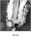
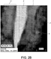
- Example 8 The effect pigment prepared in Example 8 was added to an acetate lacquer at 5 wt. %, dried, and then cross cut to give a cross sectional sample, which was examined via High Resolution Transmission Electron Microscopy (TEM). This image is shown in Fig. 2A . The same sample was also examined via Energy Dispersive X-Ray Spectroscopy (EDXS) in order to examine the distribution of the various elements coated onto the mica. This image is shown in Fig. 2B .
- TEM High Resolution Transmission Electron Microscopy
- Fig. 2A The same sample was also examined via Energy Dispersive X-Ray Spectroscopy (EDXS) in order to examine the distribution of the various elements coated onto the mica. This image is shown in Fig. 2B .
- EDXS Energy Dispersive X-Ray Spectroscopy
- the aluminum oxide deposition does not lead to a separate interlayer or coating between the two first and second high refractive index materials 1 and 2 but instead shows the aluminum oxide to be completely diffused in the second high refractive index material 2 and the diffusion occurs between the interface 7 and remote surface 9 of the second high refractive index layer 2.
- a 5% aqueous slurry containing 100 g of mica flakes (avg. particle size about 20 ⁇ m) was heated to 82°C and stirred.
- the pH of the slurry was adjusted to 3.2 with 28% HCI.
- 39% FeCl 3 was added at a rate of 1.3 g/min while the pH was maintained at 3.2 by the addition of 35% NaOH.
- the pH of the slurry was lowered to 1.5 with 28% HCI. Then, 60 g of 20% SnCl 4 ⁇ 5H 2 O were added at a rate of 1.0 g/min while the pH was maintained at 1.5 by the addition of 35% NaOH. After the addition was complete, the pH of the slurry was adjusted to 3.2 with 35% NaOH. 39% FeCl 3 was added at a rate of 1.3 g/min while the pH was maintained at 3.2 by the addition of 35% NaOH.
- the hematite outer layer is similar to that in Figures 2A and 2B . It is less dense than the first Fe 2 O 3 layer. The SnO 2 is partially diffused in the Fe 2 O 3 layer. See Figure 3B element 3.
- a 5% aqueous slurry containing 100 g of mica flakes (avg. particle size about 20 ⁇ m) was heated to 82°C and stirred.
- the pH of the slurry was adjusted to 1.5 with 28% HCI.
- 20% SnCl 4 ⁇ 5H 2 O was added at a rate of 0.8 g/min while the pH was maintained at 1.5 by the addition of 10% NaOH.
- the solution was stirred for 30 minutes and then 40% TiCl 4 was added at a rate of 1.9 g/min.
- the pH was maintained at 1.5 by the addition of 35% HCI.
- the reactor was cooled to 30°C and the pH was raised to 6.0 with 35% NaOH. Then, 25 g of 20% Na 2 Al 2 O 4 were added at a rate of 0.5 g/min while the pH was maintained at 6.0 by the addition of 25% H 2 SO 4 . After the addition was complete, the slurry was heated to 82°C. The pH of the slurry was adjusted to 3.2 with 39% FeCl 3 , and the FeCl 3 was added at a rate of 1.3 g/min. The pH was maintained at 3.2 by the addition of 35% NaOH.
- Example 10 At the desired shade, 55 mL of the slurry was filtered, and the press-cake washed with water and calcined at 850°C for 20 min. The sample was drawn down for color measurement. The resulting hue was 48 and the chroma was 79. The Al 2 O 3 wt. % based on the total weight of the calcined optical coating in the effect pigments of Example 10 was 2%.
- a 16% aqueous slurry containing 160 g of mica flakes (avg. particle size about 20 ⁇ m) was heated to 76°C and stirred.
- the pH of the slurry was adjusted to 3.3 with 28% HCI.
- 39% FeCl 3 was added at a rate of 1.3 g/min while the pH was maintained at 3.3 by addition of 35% NaOH.
- No Al 2 O 3 or SnO 2 precursor was used.
- a 10% aqueous slurry containing 200 g of mica flakes (avg. particle size about 10 ⁇ m) was heated to 82°C and stirred.
- the pH of the slurry was adjusted to 3.2 with 28% HCI.
- 39% FeCl 3 was added at a rate of 2.0 g/min while the pH was maintained at 3.2 by the addition of 35% NaOH.
- the pH of the slurry was raised to 6.0 with 35% NaOH, and the slurry cooled to 30°C. Then, 60 g of 20% Na 2 Al 2 O 4 were added at a rate of 1.5 g/min while the pH was maintained at 6.0 by the addition of 25% H 2 SO 4 . After the addition was complete, the pH of the slurry was adjusted to 3.2 with 28% HCI, and the slurry was heated to 82°C. 39% FeCl 3 was added at a rate of 2.0 g/min while the pH was maintained at 3.2 by the addition of 35% NaOH.
- a 20% aqueous slurry containing 400 g of mica flakes (avg. particle size about 10 ⁇ m) was heated to 76°C and stirred.
- the pH of the slurry was adjusted to 3.3 with 28% HCI.
- 39% FeCl 3 was added at a rate of 2.0 g/min while the pH was maintained at 3.3 by the addition of 35% NaOH.
- No Al 2 O 3 or SnO 2 precursor was used.
- each of examples 8, 9 and 10-12 included Fe 2 O 3 as the high refractive index layers in the optical coating.
- Example10 included rutile TiO 2 and Fe 2 O 3 as the high refractive index materials in the optical coating.
- Table 2 illustrates the diffused third material used (if any), the weight percent of the diffused third material, the substrate particle size, the hue, and the chroma for each of Examples 8, 9, 10, and 11, and Comparative Examples 10 and 12 after the 850°C calcination.
- a 10% aqueous slurry containing 200 g of mica flakes (avg. particle size about 10 ⁇ m) was heated to 82°C and stirred.
- the pH of the slurry was adjusted to 3.2 with 28% HCI.
- 39% FeCl 3 was added at a rate of 2.0 g/min while the pH was maintained at 3.2 by the addition of 35% NaOH.
- the pH of the slurry was raised to 7.8 with 35% NaOH. Then, 60 g of 20% Na 2 SiO 3 were added at a rate of 0.5 g/min while the pH was maintained at 7.8 by the addition of 28% HCI. After the addition was complete, the pH of the slurry was adjusted to 3.2 with 28% HCI. 39% FeCl 3 was added at a rate of 2.0 g/min while the pH was maintained at 3.2 by the addition of 35% NaOH.
- the pH was raised to 3.2 with 35% NaOH.
- 39% FeCl 3 was added at 1.1 g/min, and the pH was maintained at 3.2 with 35% NaOH.
- the pH was lowered to 1.4 with 28% HCI, and 80 g of 20% SnCl 4 ⁇ 5H 2 O was added at 2.2 g/min while maintaining the pH at 1.4 with 35% NaOH.
- the pH of the slurry was adjusted to 3.2 with 35% NaOH.
- 39% FeCl 3 was added at a rate of 1.1 g/min while maintaining the pH at 3.2 by the addition of 35% NaOH.
- the SnO 2 diffused third material wt. % based on the total weight of the calcined optical coating in the effect pigments of Example 14 was 7%.
- the total weight of the calcined optical coating in this Example included 77% Fe 2 O 3 , 14% SnO 2 (7% SnO 2 as rutile director and 7% as diffused third material), and 9% TiO 2 .
- a 10% aqueous slurry containing 200 g of mica flakes (avg. particle size about 10 ⁇ m) was heated to 76°C and stirred.
- the pH of the slurry was adjusted to 3.2 with 28% HCI.
- 39% FeCl 3 was added at a rate of 2.0 g/min while the pH was maintained at 3.2 by the addition of 35% NaOH.
- the pH of the slurry was raised to 7.8 with 35% NaOH. Then, 60 g of 20% Na 2 SiO 3 were added at a rate of 0.5 g/min while the pH was maintained at 7.8 by the addition of 28% HCI. After the addition was complete, the pH of the slurry was adjusted to 3.2 with 28% HCI. 100 g of 39% FeCl 3 was added at a rate of 2.0 g/min while the pH was maintained at 3.2 by the addition of 35% NaOH.
- a 5% aqueous slurry containing 100 g of mica flakes (avg. particle size about 10 ⁇ m) was heated 82°C and stirred.
- the pH of the slurry was adjusted to 3.2 with 28% HCI.
- 39% FeCl 3 was added at a rate 1.0 g/min while the pH was maintained at 3.2 by the addition of 35% NaOH.
- the pH of the slurry was raised to 7.8 with 35% NaOH. Then, 702 g of 20% Na 2 SiO 3 were added at a rate of 0.5 g/min while the pH was maintained at 7.8 by the addition of 28% HCI. 300 g of 39% FeCl 3 was added at a rate of 1.0 g/min while the pH was maintained at 3.2 by the addition of 35% NaOH.
- Comparing example 16 with comparative example 17 shows that there is quicker color progression using the present process.
- example 16 shows that 60 g of SiO 2 and 100 g of ferric chloride is required to reach a hue of 68 on 200 g of mica, whereas in a typical multilayer stack 700 g of SiO 2 and 300 g of ferric chloride on 100 g of mica are needed to reach the same hue.
- ranges provided herein include the stated range and any value or sub-range within the stated range.
- a range from about 10 nm to about 700 nm should be interpreted to include not only the explicitly recited limits of about 10 nm to about 700 nm but also to include individual values, such as 11 nm, 125 nm, 404.5 nm, etc., and sub-ranges, such as from about 15 nm to about 400 nm, from about 30 nm to about 375 nm, etc.
- “about” is utilized to describe a value, this is meant to encompass minor variations (up to +/- 10%) from the stated value.
Landscapes
- Chemical & Material Sciences (AREA)
- Organic Chemistry (AREA)
- Health & Medical Sciences (AREA)
- Chemical Kinetics & Catalysis (AREA)
- Medicinal Chemistry (AREA)
- Polymers & Plastics (AREA)
- Pigments, Carbon Blacks, Or Wood Stains (AREA)
- Cosmetics (AREA)
- Compounds Of Iron (AREA)
- Inorganic Compounds Of Heavy Metals (AREA)
- Paints Or Removers (AREA)
- Inks, Pencil-Leads, Or Crayons (AREA)
- Laminated Bodies (AREA)
Claims (13)
- Pigment à effet, comprenant :
une lamelle revêtue d'un revêtement optique et le revêtement optique comprenant :une première couche d'indice de réfraction élevé ;une seconde couche d'indice de réfraction élevé formée sur la première couche d'indice de réfraction élevé ; etun troisième matériau diffusé,dans lequel :la première couche d'indice de réfraction élevé est adjacente à la seconde couche d'indice de réfraction élevé et en contact avec celle-ci ;le troisième matériau diffusé est diffusé à 100 % dans l'une des première et seconde couches d'indice de réfraction élevé ou les deux, dans lequelles première et seconde couches d'indice de réfraction élevé sont formées à partir de matériaux ayant un indice de réfraction environ > 1,65 ;le troisième matériau diffusé est du SiO2 ou un oxyde métallique ; etle troisième matériau diffusé est différent des première et seconde couches d'indice de réfraction élevé. - Pigment à effet selon la revendication 1, dans lequel les première et seconde couches d'indice de réfraction élevé sont choisies dans le groupe constitué par SnO2, TiO2, Cr2O3, ZnO, ZrO2, Fe2O3, Fe3O4, les oxydes de cuivre, les oxydes de cobalt, les oxydes de manganèse, l'alumine et les mélanges de ceux-ci.
- Pigment à effet selon soit la revendication 1 soit la revendication 2, dans lequel le troisième matériau diffusé est choisi dans le groupe constitué par Al2O3, SnO2, SiO2,les oxydes de cobalt, l'oxyde de magnésium, l'oxyde de manganèse, les oxydes de cuivre, Fe2O3, Fe3O4, B2O3, TiO2, Cr2O3, ZnO, ZrO2 et les mélanges de ceux-ci.
- Pigment à effet selon la revendication 3, dans lequel le troisième matériau diffusé est choisi dans le groupe constitué par Al2O3, SnO2, SiO2 et les mélanges de ceux-ci.
- Pigment à effet selon l'une quelconque des revendications 2 à 4, dans lequel les première et seconde couches d'indice de réfraction élevé sont choisies dans le groupe constitué par TiO2, Fe2O3 et les mélanges de ceux-ci.
- Pigment à effet selon la revendication 1, dans lequel les première et seconde couches d'indice de réfraction élevé sont du TiO2 et le troisième matériau diffusé est du SiO2, alors les première et seconde couches d'indice de réfraction élevé en TiO2 sont du TiO2 rutile.
- Pigment à effet selon la revendication 1, dans lequel le matériau du revêtement optique est choisi parmi les combinaisons suivantes :
Le matériau de la première couche est formé à partir de Troisième matériau diffusé Le matériau de la seconde couche est formé à partir de Fe2O3 Al2O3 Fe2O3 Fe2O3 SnO2 Fe2O3 Fe2O3 SnO2 Fe2O3 TiO2 (rutile ou anatase) Al2O3 Fe2O3 Fe2O3 Al2O3 TiO2 (rutile ou anatase) Fe2O3 SnO2 TiO2 (rutile ou anatase) TiO2 (rutile ou anatase) SnO2 Fe2O3 Fe2O3 SnO2 TiO2 (rutile ou anatase) TiO2 (rutile ou anatase) SnO2 Fe2O3 TiO2 rutile SnO2 TiO2 rutile TiO2 (rutile ou anatase) SnO2 TiO2 (rutile ou anatase) TiO2 (rutile ou anatase) Al2O3 TiO2 (rutile ou anatase). - Pigment à effet selon l'une quelconque des revendications 1 à 7, dans lequel la lamelle est choisie dans le groupe constitué par les micas naturels et synthétiques, le talc, le kaolin, les oxydes de fer, l'oxychlorure de bismuth, les éclats de verre, SiO2, Al2O3, les éclats de céramique synthétique, la perlite, l'aluminium et le graphite.
- Pigment à effet selon l'une quelconque des revendications 1 à 8 dans lequel le troisième matériau diffusé est présent dans le revêtement optique en une quantité allant d'environ 0,5 % en poids à environ 11 % en poids, le % en poids étant par rapport au poids total du revêtement optique après calcination.
- Peinture, encre pour jet d'encre, revêtement, revêtement pour automobile, encre d'imprimerie, plastique, produit cosmétique, vernis pour des compositions de céramique ou de verre contenant les pigments à effet selon l'une quelconque des revendications précédentes.
- Procédé de fabrication d'un pigment à effet selon l'une quelconque des revendications 1-9 comprenant :
le revêtement d'une lamelle avec un revêtement optique comprenant les étapes :dépôt d'une première couche de matériau d'indice de réfraction élevé sur la lamelle ;dépôt d'une seconde couche d'indice de réfraction élevé ; etdépôt d'un troisième matériau diffusé à la suite du dépôt de la première couche d'indice de réfraction élevé et avant le dépôt de la seconde couche d'indice de réfraction élevé ouco-dépôt du troisième matériau diffusé pendant le dépôt de la première couche d'indice de réfraction élevé ou de la seconde couche d'indice de réfraction élevé, le troisième matériau diffusé déposé étant diffusé à 100 % dans soit la première couche d'indice de réfraction élevé soit la seconde couche d'indice de réfraction élevé ou les deux à condition que le troisième matériau diffusé soit différent des première et seconde couches d'indice de réfraction élevé. - Procédé d'augmentation d'une saturation à une teinte donnée pour un pigment à effet selon l'une quelconque des revendications 1-9,
le revêtement d'une lamelle avec un revêtement optique comprenant les étapes :dépôt d'une première couche d'indice de réfraction élevé sur la lamelle ;dépôt d'une seconde couche d'indice de réfraction élevé ; etdépôt d'un troisième matériau diffusé à la suite du dépôt de la première couche d'indice de réfraction élevé et avant le dépôt de la seconde couche d'indice de réfraction élevé ouco-dépôt du troisième matériau diffusé pendant le dépôt de la première ou seconde couche d'indice de réfraction élevé, le troisième matériau diffusé déposé étant diffusé à 100 % dans soit la première couche d'indice de réfraction élevé soit la seconde couche d'indice de réfraction élevé ou les deux à condition que le troisième matériau diffusé soit différent des première et seconde couches d'indice de réfraction élevé. - Pigment à effet selon la revendication 1, dans lequel :
une lamelle est revêtue d'un revêtement optique et le revêtement optique comprend :la première couche d'indice de réfraction élevé qui est du TiO2 ;la seconde couche d'indice de réfraction élevé qui est une couche de TiO2 ; etle troisième matériau diffusé qui est du SiO2.
Priority Applications (1)
| Application Number | Priority Date | Filing Date | Title |
|---|---|---|---|
| EP19181921.8A EP3578610B1 (fr) | 2014-05-28 | 2015-05-21 | Pigments à effet |
Applications Claiming Priority (3)
| Application Number | Priority Date | Filing Date | Title |
|---|---|---|---|
| US201462004007P | 2014-05-28 | 2014-05-28 | |
| US201562137918P | 2015-03-25 | 2015-03-25 | |
| PCT/US2015/031882 WO2015183674A1 (fr) | 2014-05-28 | 2015-05-21 | Pigments a effet |
Related Child Applications (2)
| Application Number | Title | Priority Date | Filing Date |
|---|---|---|---|
| EP19181921.8A Division EP3578610B1 (fr) | 2014-05-28 | 2015-05-21 | Pigments à effet |
| EP19181921.8A Division-Into EP3578610B1 (fr) | 2014-05-28 | 2015-05-21 | Pigments à effet |
Publications (3)
| Publication Number | Publication Date |
|---|---|
| EP3149089A1 EP3149089A1 (fr) | 2017-04-05 |
| EP3149089A4 EP3149089A4 (fr) | 2017-12-27 |
| EP3149089B1 true EP3149089B1 (fr) | 2019-10-02 |
Family
ID=54699589
Family Applications (2)
| Application Number | Title | Priority Date | Filing Date |
|---|---|---|---|
| EP15798867.6A Active EP3149089B1 (fr) | 2014-05-28 | 2015-05-21 | Pigments a effet |
| EP19181921.8A Active EP3578610B1 (fr) | 2014-05-28 | 2015-05-21 | Pigments à effet |
Family Applications After (1)
| Application Number | Title | Priority Date | Filing Date |
|---|---|---|---|
| EP19181921.8A Active EP3578610B1 (fr) | 2014-05-28 | 2015-05-21 | Pigments à effet |
Country Status (9)
| Country | Link |
|---|---|
| US (1) | US9815970B2 (fr) |
| EP (2) | EP3149089B1 (fr) |
| JP (1) | JP7020779B2 (fr) |
| KR (1) | KR102396623B1 (fr) |
| CN (1) | CN106536640B (fr) |
| BR (1) | BR112016027743B1 (fr) |
| ES (2) | ES2900620T3 (fr) |
| MX (1) | MX2016015556A (fr) |
| WO (1) | WO2015183674A1 (fr) |
Families Citing this family (13)
| Publication number | Priority date | Publication date | Assignee | Title |
|---|---|---|---|---|
| EP2123721B1 (fr) | 2008-04-15 | 2013-11-27 | Eckart GmbH | Pigments nacrés à base de substrats fins et minces |
| EP3034562B2 (fr) | 2014-12-19 | 2021-12-08 | Eckart GmbH | Pigments à absorption et de grande brillance et ayant un degré chromatique élevé, leur procédé de fabrication et leur utilisation |
| EP3034566B2 (fr) * | 2014-12-19 | 2022-06-08 | Eckart GmbH | Pigments à effet métallique d'une plus grande brillance et ayant un degré chromatique élevé, leur procédé de fabrication et leur utilisation |
| ES2662134T3 (es) * | 2014-12-19 | 2018-04-05 | Eckart Gmbh | Pigmentos de efecto de gran transparencia, gran cromatismo y gran brillantez, procedimiento para su preparación y uso de los mismos |
| SI3034563T1 (sl) * | 2014-12-19 | 2019-06-28 | Eckart Gmbh | Zlato obarvani efektni pigmenti z visoko kromo in visokim sijajem, postopek za njihovo pripravo in njihova uporaba |
| KR102532466B1 (ko) | 2014-12-19 | 2023-05-16 | 엑카르트 게엠베하 | 고 채도 및 고 휘도를 갖는 적색 장식용 안료, 그의 제조 방법 및 그의 용도 |
| US11820900B2 (en) | 2017-03-17 | 2023-11-21 | Merck Patent Gmbh | Interference pigments |
| CN110914371A (zh) * | 2017-04-04 | 2020-03-24 | 巴斯夫色彩与效果有限公司 | 无机效果颜料 |
| CN110128880A (zh) * | 2019-05-24 | 2019-08-16 | 上海应用技术大学 | 一种宝蓝色陶瓷喷墨打印墨水 |
| CN110283479B (zh) * | 2019-08-02 | 2021-05-25 | 四川赛和新材料科技有限责任公司 | 一种超白复合绢云母及其制备方法 |
| US20230295443A1 (en) | 2020-07-23 | 2023-09-21 | Eckart Gmbh | Solvochromic effect pigments, method of production and use thereof |
| KR102553132B1 (ko) * | 2021-06-08 | 2023-07-10 | (주)스파코 | 진주광택 안료 입자 및 이의 제조 장치 및 제조 방법 |
| CN114276700A (zh) * | 2022-01-06 | 2022-04-05 | 广西七色珠光材料股份有限公司 | 一种无钛金色珠光颜料及其制备方法和用途 |
Family Cites Families (34)
| Publication number | Priority date | Publication date | Assignee | Title |
|---|---|---|---|---|
| US4373963A (en) | 1981-09-03 | 1983-02-15 | Titan Kogyo K.K. | Lustrous pigment and process for producing same |
| JPS5876461A (ja) | 1981-10-26 | 1983-05-09 | メルク・パテント・ゲゼルシヤフト・ミツト・ベシユレンクテル・ハフツング | 透明性着色顔料およびその製造法 |
| DE3528256A1 (de) * | 1985-08-07 | 1987-02-19 | Merck Patent Gmbh | Eisenoxidbeschichtete perlglanzpigmente |
| DE3636076A1 (de) | 1986-10-23 | 1988-04-28 | Merck Patent Gmbh | Plaettchenfoermige eisenoxidpigmente |
| WO1994018276A1 (fr) * | 1993-02-11 | 1994-08-18 | Corveagh Limited | Pigment colorant et son procede de fabrication |
| JP3542388B2 (ja) | 1994-10-11 | 2004-07-14 | 株式会社資生堂 | 低次酸化チタン含有顔料及びその製造方法 |
| US5584925A (en) * | 1995-06-26 | 1996-12-17 | Thiele Kaolin Company | Chemically aggregated kaolin clay pigment and process for making the same by phosphate bonding |
| DE19618562A1 (de) | 1996-05-09 | 1997-11-13 | Merck Patent Gmbh | Plättchenförmiges Titandioxidreduktionspigment |
| DE19618569A1 (de) * | 1996-05-09 | 1997-11-13 | Merck Patent Gmbh | Mehrschichtige Interferenzpigmente |
| US6132873A (en) | 1996-09-21 | 2000-10-17 | Merck Patent Gesellschaft Mit Beschrankter Haftung | Multilayered interference pigments |
| DE19746067A1 (de) * | 1997-10-17 | 1999-04-22 | Merck Patent Gmbh | Interferenzpigmente |
| DE19817286A1 (de) * | 1998-04-18 | 1999-10-21 | Merck Patent Gmbh | Mehrschichtiges Perlglanzpigment auf Basis eines opaken Substrates |
| DE19951869A1 (de) * | 1999-10-28 | 2001-05-03 | Merck Patent Gmbh | Farbstarke Interferenzpigmente |
| US7604862B2 (en) * | 2001-07-12 | 2009-10-20 | Merck Patent Gesellschaft Mit Beschrankter Haftung | Multilayer pigments based on glass flakes |
| CN1281690C (zh) | 2001-08-10 | 2006-10-25 | 日本光研工业株式会社 | 高虹彩色氧化钛组合物及其制法 |
| DE10151844A1 (de) * | 2001-10-24 | 2003-05-08 | Merck Patent Gmbh | Farbige Interferenzpigmente |
| DE10204336A1 (de) * | 2002-02-01 | 2003-08-14 | Merck Patent Gmbh | Verwendung von Mehrschichtpigmenten im Lebensmittel- und Pharmabereich |
| EP1375601A1 (fr) * | 2002-06-28 | 2004-01-02 | MERCK PATENT GmbH | Pigments comprenant cinq couches |
| US7993444B2 (en) * | 2003-01-17 | 2011-08-09 | Basf Catalysts Llc | Multi-layer effect pigment |
| DE10346167A1 (de) * | 2003-10-01 | 2005-05-25 | Merck Patent Gmbh | Glänzende schwarze Interferenzpigmente |
| CN1323117C (zh) * | 2004-04-19 | 2007-06-27 | 付建生 | 随角异色颜料及其生产方法 |
| CN1266229C (zh) * | 2004-08-10 | 2006-07-26 | 汕头市龙华珠光颜料有限公司 | 一种随角异色的多层变色颜料及其生产方法 |
| JP2006160683A (ja) * | 2004-12-08 | 2006-06-22 | Kao Corp | 水系美爪料 |
| US7842130B2 (en) * | 2005-08-22 | 2010-11-30 | Basf Corporation | Complex inorganic effect materials |
| US20070048239A1 (en) * | 2005-08-26 | 2007-03-01 | Engelhard Corporation | Cosmetic and Personal Care Formulations with Goniochromatic Non-Quarter Wave Multi-Quadrant Multi-Layer Effect Materials |
| KR101398710B1 (ko) * | 2006-10-18 | 2014-05-27 | 바스프 코포레이션 | 색 이동을 나타내는 다층 안료 |
| WO2009016056A1 (fr) * | 2007-07-31 | 2009-02-05 | Basf Se | Pigments à effet optique variable |
| CN100562544C (zh) * | 2007-10-16 | 2009-11-25 | 汕头市龙华珠光颜料有限公司 | 一种具有强烈金属质感的金色珠光颜料及其生产方法 |
| CN101962492B (zh) * | 2009-07-24 | 2014-01-08 | 林文广 | 多层涂覆的随角异色干涉色珠光颜料 |
| DE102009037935A1 (de) * | 2009-08-19 | 2011-02-24 | Eckart Gmbh | Hochglänzende Mehrschichtperlglanzpigmente mit silberner Interferenzfarbe und enger Größenverteilung und Verfahren zu deren Herstellung |
| DE102009051171A1 (de) | 2009-10-29 | 2011-05-05 | Merck Patent Gmbh | Pigmente |
| WO2011103713A1 (fr) * | 2010-02-24 | 2011-09-01 | 汕头市龙华珠光颜料有限公司 | Nouveaux pigments à interférence flip-flop |
| EP2607432A1 (fr) * | 2011-12-21 | 2013-06-26 | Merck Patent GmbH | Pigments à effets basés sur des substrats avec un facteur de forme circulaire de 1.2-2 |
| KR101399954B1 (ko) * | 2012-09-10 | 2014-05-29 | 씨큐브 주식회사 | 높은 색강도를 갖는 간섭안료 및 그 제조 방법 |
-
2015
- 2015-05-21 MX MX2016015556A patent/MX2016015556A/es unknown
- 2015-05-21 US US14/718,501 patent/US9815970B2/en active Active
- 2015-05-21 JP JP2016570047A patent/JP7020779B2/ja active Active
- 2015-05-21 CN CN201580041051.1A patent/CN106536640B/zh active Active
- 2015-05-21 EP EP15798867.6A patent/EP3149089B1/fr active Active
- 2015-05-21 KR KR1020167034830A patent/KR102396623B1/ko active IP Right Grant
- 2015-05-21 ES ES19181921T patent/ES2900620T3/es active Active
- 2015-05-21 EP EP19181921.8A patent/EP3578610B1/fr active Active
- 2015-05-21 ES ES15798867T patent/ES2764198T3/es active Active
- 2015-05-21 BR BR112016027743-0A patent/BR112016027743B1/pt active IP Right Grant
- 2015-05-21 WO PCT/US2015/031882 patent/WO2015183674A1/fr active Application Filing
Non-Patent Citations (1)
| Title |
|---|
| None * |
Also Published As
| Publication number | Publication date |
|---|---|
| BR112016027743A2 (pt) | 2017-08-15 |
| EP3578610A1 (fr) | 2019-12-11 |
| EP3149089A4 (fr) | 2017-12-27 |
| ES2900620T3 (es) | 2022-03-17 |
| JP2017524752A (ja) | 2017-08-31 |
| JP7020779B2 (ja) | 2022-02-16 |
| KR102396623B1 (ko) | 2022-05-12 |
| EP3578610B1 (fr) | 2021-09-01 |
| US9815970B2 (en) | 2017-11-14 |
| US20150344677A1 (en) | 2015-12-03 |
| ES2764198T3 (es) | 2020-06-02 |
| CN106536640B (zh) | 2019-05-21 |
| BR112016027743B1 (pt) | 2022-04-12 |
| BR112016027743A8 (pt) | 2021-05-04 |
| MX2016015556A (es) | 2017-02-27 |
| KR20170012313A (ko) | 2017-02-02 |
| CN106536640A (zh) | 2017-03-22 |
| EP3149089A1 (fr) | 2017-04-05 |
| WO2015183674A1 (fr) | 2015-12-03 |
Similar Documents
| Publication | Publication Date | Title |
|---|---|---|
| EP3149089B1 (fr) | Pigments a effet | |
| US7226503B2 (en) | Effect pigments based on coated glass flakes | |
| JP6166594B2 (ja) | ガラスフレークに基づく多層顔料 | |
| KR101297023B1 (ko) | 특수한 입자 크기 분포의 스파클 효과 | |
| FI100599B (fi) | Sähköä johtavia levymäisiä pigmenttejä | |
| JP4065370B2 (ja) | 干渉顔料 | |
| EP3305857B1 (fr) | Pigment brillant et son procédé de production, composition contenant un pigment, et objet peint contenant un pigment | |
| CN110183875B (zh) | 一种高亮度的颜料及其制备方法和用途 | |
| CN111479883A (zh) | 效果颜料 | |
| KR20140070035A (ko) | 강한 간섭색을 갖는 진주 광택 안료 및 이를 함유하는 화장료 조성물 | |
| EP1153088B1 (fr) | Pigments a effet de couleur et leur procede de fabrication | |
| KR101903207B1 (ko) | 브릴리언트 흑색 안료 | |
| KR101132502B1 (ko) | 2종 이상의 기재 물질의 혼합물을 포함하는 개선된 효과안료 | |
| EP4365242A1 (fr) | Pigment nacré multicolore à effet scintillant amélioré et procédé de préparation associé |
Legal Events
| Date | Code | Title | Description |
|---|---|---|---|
| STAA | Information on the status of an ep patent application or granted ep patent |
Free format text: STATUS: THE INTERNATIONAL PUBLICATION HAS BEEN MADE |
|
| PUAI | Public reference made under article 153(3) epc to a published international application that has entered the european phase |
Free format text: ORIGINAL CODE: 0009012 |
|
| STAA | Information on the status of an ep patent application or granted ep patent |
Free format text: STATUS: REQUEST FOR EXAMINATION WAS MADE |
|
| 17P | Request for examination filed |
Effective date: 20170102 |
|
| AK | Designated contracting states |
Kind code of ref document: A1 Designated state(s): AL AT BE BG CH CY CZ DE DK EE ES FI FR GB GR HR HU IE IS IT LI LT LU LV MC MK MT NL NO PL PT RO RS SE SI SK SM TR |
|
| AX | Request for extension of the european patent |
Extension state: BA ME |
|
| DAV | Request for validation of the european patent (deleted) | ||
| DAX | Request for extension of the european patent (deleted) | ||
| A4 | Supplementary search report drawn up and despatched |
Effective date: 20171128 |
|
| RIC1 | Information provided on ipc code assigned before grant |
Ipc: C09C 3/06 20060101AFI20171122BHEP Ipc: C09C 1/00 20060101ALI20171122BHEP |
|
| STAA | Information on the status of an ep patent application or granted ep patent |
Free format text: STATUS: EXAMINATION IS IN PROGRESS |
|
| 17Q | First examination report despatched |
Effective date: 20180911 |
|
| GRAP | Despatch of communication of intention to grant a patent |
Free format text: ORIGINAL CODE: EPIDOSNIGR1 |
|
| STAA | Information on the status of an ep patent application or granted ep patent |
Free format text: STATUS: GRANT OF PATENT IS INTENDED |
|
| RIC1 | Information provided on ipc code assigned before grant |
Ipc: C09C 1/00 20060101ALI20190130BHEP Ipc: C08K 3/16 20060101ALI20190130BHEP Ipc: C08K 3/34 20060101ALI20190130BHEP Ipc: C09C 3/06 20060101AFI20190130BHEP |
|
| INTG | Intention to grant announced |
Effective date: 20190227 |
|
| GRAJ | Information related to disapproval of communication of intention to grant by the applicant or resumption of examination proceedings by the epo deleted |
Free format text: ORIGINAL CODE: EPIDOSDIGR1 |
|
| STAA | Information on the status of an ep patent application or granted ep patent |
Free format text: STATUS: EXAMINATION IS IN PROGRESS |
|
| GRAP | Despatch of communication of intention to grant a patent |
Free format text: ORIGINAL CODE: EPIDOSNIGR1 |
|
| STAA | Information on the status of an ep patent application or granted ep patent |
Free format text: STATUS: GRANT OF PATENT IS INTENDED |
|
| INTC | Intention to grant announced (deleted) | ||
| INTG | Intention to grant announced |
Effective date: 20190716 |
|
| GRAS | Grant fee paid |
Free format text: ORIGINAL CODE: EPIDOSNIGR3 |
|
| GRAA | (expected) grant |
Free format text: ORIGINAL CODE: 0009210 |
|
| STAA | Information on the status of an ep patent application or granted ep patent |
Free format text: STATUS: THE PATENT HAS BEEN GRANTED |
|
| AK | Designated contracting states |
Kind code of ref document: B1 Designated state(s): AL AT BE BG CH CY CZ DE DK EE ES FI FR GB GR HR HU IE IS IT LI LT LU LV MC MK MT NL NO PL PT RO RS SE SI SK SM TR |
|
| REG | Reference to a national code |
Ref country code: GB Ref legal event code: FG4D |
|
| REG | Reference to a national code |
Ref country code: CH Ref legal event code: EP Ref country code: AT Ref legal event code: REF Ref document number: 1186133 Country of ref document: AT Kind code of ref document: T Effective date: 20191015 |
|
| REG | Reference to a national code |
Ref country code: DE Ref legal event code: R096 Ref document number: 602015039162 Country of ref document: DE |
|
| REG | Reference to a national code |
Ref country code: IE Ref legal event code: FG4D |
|
| REG | Reference to a national code |
Ref country code: SE Ref legal event code: TRGR |
|
| REG | Reference to a national code |
Ref country code: NL Ref legal event code: MP Effective date: 20191002 |
|
| REG | Reference to a national code |
Ref country code: LT Ref legal event code: MG4D |
|
| REG | Reference to a national code |
Ref country code: AT Ref legal event code: MK05 Ref document number: 1186133 Country of ref document: AT Kind code of ref document: T Effective date: 20191002 |
|
| PG25 | Lapsed in a contracting state [announced via postgrant information from national office to epo] |
Ref country code: LT Free format text: LAPSE BECAUSE OF FAILURE TO SUBMIT A TRANSLATION OF THE DESCRIPTION OR TO PAY THE FEE WITHIN THE PRESCRIBED TIME-LIMIT Effective date: 20191002 Ref country code: GR Free format text: LAPSE BECAUSE OF FAILURE TO SUBMIT A TRANSLATION OF THE DESCRIPTION OR TO PAY THE FEE WITHIN THE PRESCRIBED TIME-LIMIT Effective date: 20200103 Ref country code: NO Free format text: LAPSE BECAUSE OF FAILURE TO SUBMIT A TRANSLATION OF THE DESCRIPTION OR TO PAY THE FEE WITHIN THE PRESCRIBED TIME-LIMIT Effective date: 20200102 Ref country code: AT Free format text: LAPSE BECAUSE OF FAILURE TO SUBMIT A TRANSLATION OF THE DESCRIPTION OR TO PAY THE FEE WITHIN THE PRESCRIBED TIME-LIMIT Effective date: 20191002 Ref country code: PL Free format text: LAPSE BECAUSE OF FAILURE TO SUBMIT A TRANSLATION OF THE DESCRIPTION OR TO PAY THE FEE WITHIN THE PRESCRIBED TIME-LIMIT Effective date: 20191002 Ref country code: FI Free format text: LAPSE BECAUSE OF FAILURE TO SUBMIT A TRANSLATION OF THE DESCRIPTION OR TO PAY THE FEE WITHIN THE PRESCRIBED TIME-LIMIT Effective date: 20191002 Ref country code: BG Free format text: LAPSE BECAUSE OF FAILURE TO SUBMIT A TRANSLATION OF THE DESCRIPTION OR TO PAY THE FEE WITHIN THE PRESCRIBED TIME-LIMIT Effective date: 20200102 Ref country code: PT Free format text: LAPSE BECAUSE OF FAILURE TO SUBMIT A TRANSLATION OF THE DESCRIPTION OR TO PAY THE FEE WITHIN THE PRESCRIBED TIME-LIMIT Effective date: 20200203 Ref country code: LV Free format text: LAPSE BECAUSE OF FAILURE TO SUBMIT A TRANSLATION OF THE DESCRIPTION OR TO PAY THE FEE WITHIN THE PRESCRIBED TIME-LIMIT Effective date: 20191002 Ref country code: NL Free format text: LAPSE BECAUSE OF FAILURE TO SUBMIT A TRANSLATION OF THE DESCRIPTION OR TO PAY THE FEE WITHIN THE PRESCRIBED TIME-LIMIT Effective date: 20191002 |
|
| PG25 | Lapsed in a contracting state [announced via postgrant information from national office to epo] |
Ref country code: HR Free format text: LAPSE BECAUSE OF FAILURE TO SUBMIT A TRANSLATION OF THE DESCRIPTION OR TO PAY THE FEE WITHIN THE PRESCRIBED TIME-LIMIT Effective date: 20191002 Ref country code: IS Free format text: LAPSE BECAUSE OF FAILURE TO SUBMIT A TRANSLATION OF THE DESCRIPTION OR TO PAY THE FEE WITHIN THE PRESCRIBED TIME-LIMIT Effective date: 20200224 Ref country code: CZ Free format text: LAPSE BECAUSE OF FAILURE TO SUBMIT A TRANSLATION OF THE DESCRIPTION OR TO PAY THE FEE WITHIN THE PRESCRIBED TIME-LIMIT Effective date: 20191002 Ref country code: RS Free format text: LAPSE BECAUSE OF FAILURE TO SUBMIT A TRANSLATION OF THE DESCRIPTION OR TO PAY THE FEE WITHIN THE PRESCRIBED TIME-LIMIT Effective date: 20191002 |
|
| REG | Reference to a national code |
Ref country code: ES Ref legal event code: FG2A Ref document number: 2764198 Country of ref document: ES Kind code of ref document: T3 Effective date: 20200602 |
|
| PG25 | Lapsed in a contracting state [announced via postgrant information from national office to epo] |
Ref country code: AL Free format text: LAPSE BECAUSE OF FAILURE TO SUBMIT A TRANSLATION OF THE DESCRIPTION OR TO PAY THE FEE WITHIN THE PRESCRIBED TIME-LIMIT Effective date: 20191002 |
|
| REG | Reference to a national code |
Ref country code: DE Ref legal event code: R097 Ref document number: 602015039162 Country of ref document: DE |
|
| PG2D | Information on lapse in contracting state deleted |
Ref country code: IS |
|
| PG25 | Lapsed in a contracting state [announced via postgrant information from national office to epo] |
Ref country code: RO Free format text: LAPSE BECAUSE OF FAILURE TO SUBMIT A TRANSLATION OF THE DESCRIPTION OR TO PAY THE FEE WITHIN THE PRESCRIBED TIME-LIMIT Effective date: 20191002 Ref country code: EE Free format text: LAPSE BECAUSE OF FAILURE TO SUBMIT A TRANSLATION OF THE DESCRIPTION OR TO PAY THE FEE WITHIN THE PRESCRIBED TIME-LIMIT Effective date: 20191002 Ref country code: DK Free format text: LAPSE BECAUSE OF FAILURE TO SUBMIT A TRANSLATION OF THE DESCRIPTION OR TO PAY THE FEE WITHIN THE PRESCRIBED TIME-LIMIT Effective date: 20191002 Ref country code: IS Free format text: LAPSE BECAUSE OF FAILURE TO SUBMIT A TRANSLATION OF THE DESCRIPTION OR TO PAY THE FEE WITHIN THE PRESCRIBED TIME-LIMIT Effective date: 20200202 |
|
| PLBE | No opposition filed within time limit |
Free format text: ORIGINAL CODE: 0009261 |
|
| STAA | Information on the status of an ep patent application or granted ep patent |
Free format text: STATUS: NO OPPOSITION FILED WITHIN TIME LIMIT |
|
| PG25 | Lapsed in a contracting state [announced via postgrant information from national office to epo] |
Ref country code: SM Free format text: LAPSE BECAUSE OF FAILURE TO SUBMIT A TRANSLATION OF THE DESCRIPTION OR TO PAY THE FEE WITHIN THE PRESCRIBED TIME-LIMIT Effective date: 20191002 Ref country code: SK Free format text: LAPSE BECAUSE OF FAILURE TO SUBMIT A TRANSLATION OF THE DESCRIPTION OR TO PAY THE FEE WITHIN THE PRESCRIBED TIME-LIMIT Effective date: 20191002 |
|
| 26N | No opposition filed |
Effective date: 20200703 |
|
| PG25 | Lapsed in a contracting state [announced via postgrant information from national office to epo] |
Ref country code: SI Free format text: LAPSE BECAUSE OF FAILURE TO SUBMIT A TRANSLATION OF THE DESCRIPTION OR TO PAY THE FEE WITHIN THE PRESCRIBED TIME-LIMIT Effective date: 20191002 |
|
| PG25 | Lapsed in a contracting state [announced via postgrant information from national office to epo] |
Ref country code: LI Free format text: LAPSE BECAUSE OF NON-PAYMENT OF DUE FEES Effective date: 20200531 Ref country code: MC Free format text: LAPSE BECAUSE OF FAILURE TO SUBMIT A TRANSLATION OF THE DESCRIPTION OR TO PAY THE FEE WITHIN THE PRESCRIBED TIME-LIMIT Effective date: 20191002 Ref country code: CH Free format text: LAPSE BECAUSE OF NON-PAYMENT OF DUE FEES Effective date: 20200531 |
|
| REG | Reference to a national code |
Ref country code: BE Ref legal event code: MM Effective date: 20200531 |
|
| GBPC | Gb: european patent ceased through non-payment of renewal fee |
Effective date: 20200521 |
|
| PG25 | Lapsed in a contracting state [announced via postgrant information from national office to epo] |
Ref country code: LU Free format text: LAPSE BECAUSE OF NON-PAYMENT OF DUE FEES Effective date: 20200521 |
|
| PG25 | Lapsed in a contracting state [announced via postgrant information from national office to epo] |
Ref country code: IE Free format text: LAPSE BECAUSE OF NON-PAYMENT OF DUE FEES Effective date: 20200521 Ref country code: GB Free format text: LAPSE BECAUSE OF NON-PAYMENT OF DUE FEES Effective date: 20200521 |
|
| PG25 | Lapsed in a contracting state [announced via postgrant information from national office to epo] |
Ref country code: BE Free format text: LAPSE BECAUSE OF NON-PAYMENT OF DUE FEES Effective date: 20200531 |
|
| PGFP | Annual fee paid to national office [announced via postgrant information from national office to epo] |
Ref country code: SE Payment date: 20210521 Year of fee payment: 7 Ref country code: TR Payment date: 20210507 Year of fee payment: 7 |
|
| PG25 | Lapsed in a contracting state [announced via postgrant information from national office to epo] |
Ref country code: MT Free format text: LAPSE BECAUSE OF FAILURE TO SUBMIT A TRANSLATION OF THE DESCRIPTION OR TO PAY THE FEE WITHIN THE PRESCRIBED TIME-LIMIT Effective date: 20191002 Ref country code: CY Free format text: LAPSE BECAUSE OF FAILURE TO SUBMIT A TRANSLATION OF THE DESCRIPTION OR TO PAY THE FEE WITHIN THE PRESCRIBED TIME-LIMIT Effective date: 20191002 |
|
| PG25 | Lapsed in a contracting state [announced via postgrant information from national office to epo] |
Ref country code: MK Free format text: LAPSE BECAUSE OF FAILURE TO SUBMIT A TRANSLATION OF THE DESCRIPTION OR TO PAY THE FEE WITHIN THE PRESCRIBED TIME-LIMIT Effective date: 20191002 |
|
| REG | Reference to a national code |
Ref country code: SE Ref legal event code: EUG |
|
| PG25 | Lapsed in a contracting state [announced via postgrant information from national office to epo] |
Ref country code: SE Free format text: LAPSE BECAUSE OF NON-PAYMENT OF DUE FEES Effective date: 20220522 |
|
| REG | Reference to a national code |
Ref country code: DE Ref legal event code: R081 Ref document number: 602015039162 Country of ref document: DE Owner name: SUN CHEMICAL B.V., NL Free format text: FORMER OWNER: BASF SE, 67063 LUDWIGSHAFEN, DE |
|
| P01 | Opt-out of the competence of the unified patent court (upc) registered |
Effective date: 20230520 |
|
| PGFP | Annual fee paid to national office [announced via postgrant information from national office to epo] |
Ref country code: IT Payment date: 20230420 Year of fee payment: 9 Ref country code: FR Payment date: 20230420 Year of fee payment: 9 Ref country code: ES Payment date: 20230601 Year of fee payment: 9 Ref country code: DE Payment date: 20230419 Year of fee payment: 9 |