EP3148411B1 - Imaging apparatus, imaging method and medical imaging system - Google Patents
Imaging apparatus, imaging method and medical imaging system Download PDFInfo
- Publication number
- EP3148411B1 EP3148411B1 EP15729582.5A EP15729582A EP3148411B1 EP 3148411 B1 EP3148411 B1 EP 3148411B1 EP 15729582 A EP15729582 A EP 15729582A EP 3148411 B1 EP3148411 B1 EP 3148411B1
- Authority
- EP
- European Patent Office
- Prior art keywords
- speckle
- numerical aperture
- fluid
- light
- imaging apparatus
- Prior art date
- Legal status (The legal status is an assumption and is not a legal conclusion. Google has not performed a legal analysis and makes no representation as to the accuracy of the status listed.)
- Not-in-force
Links
Images


Classifications
-
- A—HUMAN NECESSITIES
- A61—MEDICAL OR VETERINARY SCIENCE; HYGIENE
- A61B—DIAGNOSIS; SURGERY; IDENTIFICATION
- A61B1/00—Instruments for performing medical examinations of the interior of cavities or tubes of the body by visual or photographical inspection, e.g. endoscopes; Illuminating arrangements therefor
- A61B1/00002—Operational features of endoscopes
- A61B1/00043—Operational features of endoscopes provided with output arrangements
- A61B1/00045—Display arrangement
-
- A—HUMAN NECESSITIES
- A61—MEDICAL OR VETERINARY SCIENCE; HYGIENE
- A61B—DIAGNOSIS; SURGERY; IDENTIFICATION
- A61B1/00—Instruments for performing medical examinations of the interior of cavities or tubes of the body by visual or photographical inspection, e.g. endoscopes; Illuminating arrangements therefor
- A61B1/04—Instruments for performing medical examinations of the interior of cavities or tubes of the body by visual or photographical inspection, e.g. endoscopes; Illuminating arrangements therefor combined with photographic or television appliances
- A61B1/044—Instruments for performing medical examinations of the interior of cavities or tubes of the body by visual or photographical inspection, e.g. endoscopes; Illuminating arrangements therefor combined with photographic or television appliances for absorption imaging
-
- A—HUMAN NECESSITIES
- A61—MEDICAL OR VETERINARY SCIENCE; HYGIENE
- A61B—DIAGNOSIS; SURGERY; IDENTIFICATION
- A61B5/00—Measuring for diagnostic purposes; Identification of persons
- A61B5/0059—Measuring for diagnostic purposes; Identification of persons using light, e.g. diagnosis by transillumination, diascopy, fluorescence
- A61B5/0062—Arrangements for scanning
- A61B5/0066—Optical coherence imaging
-
- A—HUMAN NECESSITIES
- A61—MEDICAL OR VETERINARY SCIENCE; HYGIENE
- A61B—DIAGNOSIS; SURGERY; IDENTIFICATION
- A61B5/00—Measuring for diagnostic purposes; Identification of persons
- A61B5/02—Detecting, measuring or recording for evaluating the cardiovascular system, e.g. pulse, heart rate, blood pressure or blood flow
- A61B5/026—Measuring blood flow
- A61B5/0261—Measuring blood flow using optical means, e.g. infrared light
-
- A—HUMAN NECESSITIES
- A61—MEDICAL OR VETERINARY SCIENCE; HYGIENE
- A61B—DIAGNOSIS; SURGERY; IDENTIFICATION
- A61B5/00—Measuring for diagnostic purposes; Identification of persons
- A61B5/74—Details of notification to user or communication with user or patient; User input means
- A61B5/742—Details of notification to user or communication with user or patient; User input means using visual displays
-
- A—HUMAN NECESSITIES
- A61—MEDICAL OR VETERINARY SCIENCE; HYGIENE
- A61B—DIAGNOSIS; SURGERY; IDENTIFICATION
- A61B5/00—Measuring for diagnostic purposes; Identification of persons
- A61B5/05—Detecting, measuring or recording for diagnosis by means of electric currents or magnetic fields; Measuring using microwaves or radio waves
- A61B5/053—Measuring electrical impedance or conductance of a portion of the body
- A61B5/0538—Measuring electrical impedance or conductance of a portion of the body invasively, e.g. using a catheter
Definitions
- the present technology is related to a fluid analysis device, a fluid analysis method, a program and a fluid analysis system, and specifically, is related to a technology of detecting and analyzing fluid such as a blood flow.
- a technology of an imaging system that captures a coherent light image of a blood vessel area is disclosed. According to this technology, for example, an internal blood vessel of an organ and blood that covers a living body surface can be distinguished.
- the patent US7113817 B1 discloses the features in the preambles of claims 1 and 14.
- the disclosed apparatus and method relate to speckle imaging of blood flow.
- the exposure time of the camera used for the imaging is optimized for maximizing the speckle contrast.
- a main object of the disclosure is to provide a fluid analysis device, a fluid analysis method, a program, and a fluid analysis system that can enhance the detection accuracy of a flow of fluid.
- the detection accuracy of the flow of the fluid can be enhanced.
- the effects described herein are examples, are not intended to limit the disclosure, and may be any one of effects described in the disclosure.
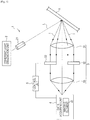
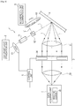
- Fig. 1 is a diagram schematically illustrating the fluid analysis device 1 of the embodiment.
- the fluid analysis device 1 of the embodiment includes a coherent light irradiation unit 2 that irradiates the fluid X with coherent light L, an image forming optical system 3 that forms an image with light applied to the fluid X, and a data acquiring unit 4 that acquires the speckle data of the fluid, and the image forming optical system 3 adjusts the numerical aperture based on the speckle data.
- the fluid X is not particularly limited as long as it has the light scattering material. However, it is preferable that blood is used. At this point, the fluid analysis device 1 functions as a blood flow analysis device, so that while performing medical treatment on an animal such as a human, the fluid analysis device 1 can detect the blood flow thereof and analyze the blood flow.
- the fluid X is generally described as the blood flow X.
- the coherent light irradiation unit 2 included in the fluid analysis device 1 of the embodiment irradiates the blood flow X with the coherent light L.
- the coherent light irradiation unit 2 can be used as a light source for irradiation with the coherent light L.
- the coherent light L is not particularly limited as long as the speckle data can be obtained from light applied to the blood flow X, and a laser beam can be used as the coherent light L.
- a beam expander 21 can be provided between the coherent light irradiation unit 2 and the blood flow X.
- the image forming optical system 3 included in the fluid analysis device 1 of the embodiment forms an image with the light applied to the blood flow X.
- the image forming optical system 3 adjusts the numerical aperture based on the speckle data acquired by the data acquiring unit 4 as described below.
- the speckle data is data of the speckle contrast, and at this point, the image forming optical system 3 adjusts the numerical aperture so that the speckle contrast becomes the maximum. Accordingly, the detection accuracy of the flow of the blood flow X can be enhanced.
- the details of the speckle contrast are described below.
- the image forming optical system 3 mainly includes a first lens 31 that functions as a condensing lens that focuses the light 1 applied to the blood flow X, a diaphragm 32 that can change the opening diameter in a plane direction parallel to a Fourier surface, and a second lens 33 that functions as an imaging lens focusing on the imaging device 41 described below.
- the image forming optical system 3 can adjust the numerical aperture by adjusting the size of the diaphragm 32.
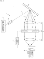
- Fig. 2 is a diagram illustrating a concept of another device configuration of the fluid analysis device 1.
- the image forming optical system 3 may have an optional spatial optical modulator 34, instead of the diaphragm 32.
- the speckle contrast of the speckle image can be caused to be the maximum by controlling the opening of the spatial optical modulator 34, instead of adjusting the size of the diaphragm 32.
- the fluid analysis device 1 of the embodiment can be operated by using a digital micro device (DMD).
- a digital micro device DMD
- an optional light valve that can electronically or mechanically control the numerical aperture can be provided.
- an optional optical modulating element such as a mechanical iris diaphragm, a liquid crystal shutter, an electrochromic device, and an electrophoretic device can be used.
- the data acquiring unit 4 included in the fluid analysis device 1 of the embodiment acquires the speckle data of the blood flow X irradiated with the coherent light L.
- the data acquiring unit 4 can include the imaging device 41as a CCD camera, and it is possible to capture the speckle image of the blood flow X with the imaging device 41 and to acquire the speckle data.
- the data acquiring unit 4 can transmit a signal relating to the acquired speckle data to a control unit 5 described below, and adjusts the numerical aperture of the image forming optical system 3 by the control unit 5. Also, in the fluid analysis device 1 of the embodiment, in order to statistically process a speckle pattern described below and to accurately obtain data of the speckle contrast with respect to the numerical aperture, a pixel size of the image captured by the imaging device 41 is preferably smaller than a speckle grain size.
- the fluid analysis device 1 of the embodiment can further include the control unit 5.
- a central processing unit (CPU), a memory, an input and output interface unit, a hard disk or the like may be provided. Details thereof are described in the fluid analysis method described below.
- the control unit 5 can generate the speckle data for each numerical aperture based on the speckle data acquired by the data acquiring unit 4.
- the control unit 5 can generate data of the speckle contrast for each numerical aperture.
- the control unit 5 can adjust the numerical aperture of the diaphragm 32 in the image forming optical system 3 based on the speckle data acquired by the data acquiring unit 4.
- the fluid analysis method includes a data acquiring step of irradiating the blood flow X with coherent light and acquiring speckle data of the fluid irradiated with the coherent light and a step of adjusting the numerical aperture of the image forming optical system 3 for forming an image with the light applied to the fluid based on the speckle data.
- the numerical aperture of the diaphragm 32 of the image forming optical system 3 is adjusted to an optimum value by the control unit 5 so that the movement of the scattered fluid of the blood flow X can be most distinctly observed from the speckle data acquired by the data acquiring unit 4.
- the image forming optical system 3 adjusts the numerical aperture so that the speckle contrast becomes the maximum.
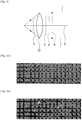
- Fig. 3 is a diagram illustrating a state of forming an image with light using the image forming optical system 3.
- rays near an optical axis l 0 of the light applied to the blood flow X are not disturbed on the wave surface, but the rays are disturbed on the wave surface as it gets farther from the optical axis (in the drawing, see references a and b), and a speckle phenomenon occurs due to the random interference of the scattered wave.
- the imaging device 41 can capture a spot pattern image (speckle image) of the blood flow X.
- the image forming optical system 3 causes the numerical aperture to be great so that angles and directions of the incident light and phases vary and the scattered waves are equalized. Therefore, the speckle contrast decreases. Meanwhile, when the image forming optical system 3 causes the numerical aperture to be small, the speckle contrast becomes great. Further, if the wave front aberration in the image forming optical system 3 becomes small, the main phase difference occurs due to the scatter from a rough surface of the blood flow X. At this point, if the phase difference applied by the scatter from the blood flow X is in a range of 1 cycle (-pi to pi), a phenomenon called "undeveloped speckle" by the image forming optical system 3 is generated so that a speckle pattern changes and the speckle contrast decreases on the imaging surface.
- the flow measurement sensitivity or the accuracy becomes high. Therefore, if the spatial resolution is negligible, the flow can be measured with high accuracy by reducing the numerical aperture of the image forming optical system 3 to be as small as possible in a range in which the speckle is not undeveloped.
- the numerical aperture at this point varies in response to the phase difference occurring due to the blood flow X which is a measuring object, the aberration of the image forming optical system 3, the numerical aperture of the illumination system, and the sensitivity of the two-dimensional imaging device 41.
- the image forming optical system 3 changes the numerical aperture based on the speckle data (intensity of speckle contrast, speckle pattern, or the like) acquired by capturing the speckle image by the data acquiring unit 4.
- an optional optical modulating element such as a mechanical iris diaphragm, a liquid crystal shutter, an electrochromic device, and an electrophoretic device can be used.
- Figs. 4A and 4B are diagrams illustrating an example of the speckle image.
- a complex amplitude of the light made on an image surface by n points of a dispersed object such as the blood flow X is expressed by Expression (2) below.
- sigma represents a standard deviation between Ar and Ai.
- the speckle expressed by the probability density functions can be called a sufficiently developed speckle, and a pattern illustrated in Fig. 4A is an example thereof.
- rho is a correlation coefficient between Ar and Ai
- delta Ar Ar - ⁇ Ar>
- delta Ai Ai - ⁇ Ai>.
- the speckle expressed by the probability density function is called an undeveloped speckle, and a pattern illustrated in Fig. 4B is an example.
- the control unit 5 can convert information of the blood flow X into the speckle contrast by performing data processing on the speckle data acquired by the data acquiring unit 4.
- the speckle contrast (CS) is expressed by Expression (9) below.
- the velocity of the light scattered fluid such as the blood flow X is inversely proportional to a square of the speckle contrast.
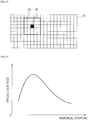
- Fig. 5 is a diagram schematically illustrating a state of mapping the speckle image. With respect to the speckle image illustrated in Figs. 4A and 4B , the entire range of an image 41 for each pixel is mapped as illustrated in Fig. 5 so that the image of the blood flow X can be generated, and the movement and the flow of the blood flow X can be observed.
- an area of the image 41 in which statistical processing for calculating the speckle contrast is performed is set to be a square area 42 in which five pixels are arranged respectively in horizontal and vertical directions.
- the speckle contrast in a center 43 of the square area 42 can be calculated as the speckle contrast of the square area.
- An optional range can be set as the statistical processing area depending on the resolution of the speckle image and the measurement accuracy of the flow of the blood flow X.
- Fig. 6 is a graph illustrating a relationship between the numerical aperture and the speckle contrast.
- the image forming optical system 3 can adjust the numerical aperture so that the speckle contrast becomes the maximum. Accordingly, the detection accuracy of the flow of the blood flow X can be enhanced.
- the data acquiring unit 4 acquires data of speckle contrast other than that of the fluid such as the blood flow X, and the image forming optical system 3 can adjust the numerical aperture so that the speckle contrast of the blood flow X and the speckle contrast other than that of the blood flow X becomes the maximum.
- Fig. 7 is a graph illustrating a relationship between the numerical aperture and the speckle contrast. Particularly, Fig. 7 is a graph illustrating the numerical aperture and the difference between the speckle contrast of the blood flow X and the speckle contrast other than that of the blood flow X.
- the detection accuracy of the flow of the blood flow X is increased by adjusting the numerical aperture so that the difference (difference in Fig. 7 ) between the speckle contrast of the blood flow X (flow in Fig. 7 ) and the speckle contrast other than that of the blood flow X (phantom in Fig. 7 ) becomes the maximum.
- the image forming optical system 3 may adjust the numerical aperture based on the granularity or the stripe density of the speckle image.
- the speckle image illustrated in Fig. 4A has granularity greater than that of the speckle image illustrated in Fig. 4B .
- the speckle image illustrated in Fig. 4B has stripe density greater than that of the speckle image illustrated in Fig. 4A .
- the control unit 5 can control the numerical aperture in response to the value of the granularity and stripe density thereof, by distributing, for example, how much pixels having luminance values which are the same or in a certain range are continued and adjacent to each other. In this manner, the image forming optical system 3 can adjust the numerical aperture so that the granularity of the speckle image becomes greater.
- the image forming optical system 3 adjusts the numerical aperture based on the speckle data, it is possible to enhance the detection accuracy of the flow of the blood flow X.
- the blood flow X can be accurately observed by causing the image forming optical system 3 to adjust the numerical aperture so that the speckle contrast becomes the maximum by using the data of the speckle contrast as the speckle data.
- the blood flow X can be accurately observed by causing the image forming optical system 3 to adjust the numerical aperture so that the difference between the speckle contrast of the blood flow X and the speckle contrast other than that of the blood flow X becomes the maximum.
- Fig. 8 is a diagram schematically illustrating a configuration example of the fluid analysis device 11 of the modification example of the embodiment.
- the fluid analysis device 11 of the modification example of the embodiment is different from the fluid analysis device 1 of the first embodiment described above in that the fluid analysis device 11 includes an incoherent light irradiation unit 6 that irradiates the blood flow X with incoherent light L'. Therefore, herein, the configuration of the incoherent light irradiation unit 6 and the function thereof are mainly described.
- the image forming optical system 3 can adjust the diaphragm 32 so that the size of the aperture becomes optimal for the speckle image and the bright field and fluorescence image.
- the incoherent light irradiation unit 6 is not particularly limited, a visible light laser with low coherency such as a Xe lamp can be used.
- a rotating chopper 61 may be provided between the coherent light irradiation unit 2 and the beam expander 21.
- a polarization beam splitter 62 may be provided between the beam expander 21 and the blood flow X.
- the parallel light from the Xe lamp can pass through a rotating band pass filter 63 that can block the red light, the green light, and the blue light at an even time interval, and be incident to and reflected on the polarization beam splitter 62.
- the rotating chopper 61 and the rotating band pass filter 63 can be synchronized, and the same position of the blood flow X can be illuminated with red, green, and blue naturally emitted light and a near infrared laser beam at a specific time interval.
- the control unit 5 can be provided in a different device from the fluid analysis devices 1, and 11, compared with the fluid analysis device 1 of the first embodiment and the fluid analysis device 11 of the modification example of the first embodiment. Accordingly, for example, the control unit 5 can adjust the numerical aperture based on the speckle data in the image forming optical system 3 of the fluid analysis device 1 via a network.
- the network includes, for example, a public network such as the Internet, a telephone network, a satellite communication network, and a broadcast communication path, or a leased line network such as a wide area network (WAN), a local area network (LAN), an internet protocol-virtual private network (IP-VPN), an Ethernet (registered trade mark), and a wireless LAN, regardless of being wired or wireless.
- a public network such as the Internet
- a telephone network such as a satellite communication network, and a broadcast communication path
- a leased line network such as a wide area network (WAN), a local area network (LAN), an internet protocol-virtual private network (IP-VPN), an Ethernet (registered trade mark), and a wireless LAN, regardless of being wired or wireless.
- IP-VPN internet protocol-virtual private network
- Ethernet registered trade mark
- wireless LAN regardless of being wired or wireless.
- the network may be a communication channel network exclusively provided in the fluid analysis system of the embodiment.
- a server, an image display apparatus, or the like may be provided in the fluid analysis system of the embodiment.
- the fluid analysis devices 1, and 11, a server, and an image display apparatus may be directly connected, or may be connected in a communicable manner via a network.
- Fig. 13 shows a diagram of a medical imaging system, specifically, an endoscopy system 130, according to some embodiments.
- the endoscopy system 130 has a light source 132.
- Light source 132 may include a coherent light irradiation unit 2, an incoherent light illumination unit 6, or both a coherent light irradiation unit 2, an incoherent light illumination unit 6, as discussed above.
- the light source 132 emits light that is provided to an endoscope body 134 to perform endoscopy.
- the endoscope body 134 may include a lighting optical system 136 to receive the light from light source 132.
- the lighting optical system 136 may include any suitable optical components, such as one or more lenses, one or more optical fibers, a beam expander 21, a beam splitter such as polarization beam splitter 62, a filter such as rotating band pass filter 63, or any suitable combination of such components.
- the techinques described herein are not limited to the lighting optical system 136 being included within the endoscope body 134, as in some embodiments on or more components of the lighting optical system 136 may be provided external to the endoscope body 134.
- Light may be emitted from the lighting optical system to 136 to illuminate a region of an organism, such as the human body, to perform endoscopy.
- the endoscope body 134 may also include an image forming optical system 3 and a data acquiring unit 4 which may include an imaging element 41,as described above.
- the endoscopy system 130 may include a control unit 5 that receives data from the data acquiring unit 4 and controls the image forming optical system 3.
- the control unit 5 and/or the data acquiring unit 4 may include a processor that processes the received image data to obtain speckle data, such as a speckle contrast.
- the control unit 5 may control the light source 132.
- the endoscopy system 130 may include a display 138 for display of an image produced by the data acquiring unit 4 and/or the control unit 5.
- Display 138 may be any suitable type of display for displaying images to a user.
- a medical imaging system may include a microscope including an optical apparatus as described above and shown in FIG. 1 , by way of example.
- Fluid is observed using the fluid analysis device illustrated in Fig. 1 .
- an external resonance semiconductor laser (CW oscillation, wavelength: 780 nanometer, single vertical mode, line width: 300 kHz (1 ms), transverse mode: TEM00, output number: up to 100 mW) manufactured by Sacher Lasertechnik is used as a light source.
- CW oscillation wavelength: 780 nanometer, single vertical mode, line width: 300 kHz (1 ms), transverse mode: TEM00, output number: up to 100 mW
- Sacher Lasertechnik is used as a light source.
- a laser beam emitted from the light source is expanded by a beam expander manufactured by Edmund Optics, and a phantom formed as a channel is irradiated with a parallel beam.
- alumina particles as a light diffusion agent and red ink as a light absorbent are mixed in an ultraviolet curing resin, and an absorption coefficient and an equivalent scatter coefficient in a wavelength of 780 nanometer are set to be 0.07 per millimeter and 1.08 per millimeter so as to be the same as those of an inner wall of a stomach of a human.
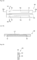
- Figs. 9A to 9C are diagrams illustrating a configuration of the tool 100 circulate the fluid.
- a cross-sectional view taken along line IXB-IXB in a front view of Fig. 9A is illustrated in Fig. 9B
- a cross-sectional view taken along line IXC-IXC is illustrated in Fig. 9C .
- an opening portion 101 and a channel 102 of which a cross section has a 1 millimeter angle are formed in positions having a depth of 200 micrometers from an observation surface, and a tube is connected to an injection and discharge port provided on a rear side with respect to the observation surface.
- artificial blood flows from the opening portion 101 to the channel 102 at a velocity of about 10 millimeter/sec with a syringe pump.
- drinkable milk is used as the artificial blood.
- a reference number 103 denotes a focusing member.
- the diaphragm 32 iris diaphragm
- a diameter of the aperture is adjustable in a range of 3 millimeter to 15 millimeter.
- a focus is adjusted so that an imaging surface of a CCD camera is identical to an image surface of the data acquiring unit 4.
- An industrial CCD camera (XCD-V60) manufactured by Sony Corporation is used as an imaging CCD camera.
- the camera has a pixel size sufficiently smaller than a speckle grain size so that an intensity of a speckle pattern is a resolution sufficient for statistical processing (square of which one side is 7.4 micrometers).
- a signal from the CCD camera is output as a bitmap file of 8 bits, VGA, 60 fps, and is obtained by a PC according to IEEE1394b, to perform statistical processing.
- An image of the flow is generated by setting an image area for performing statistical processing in order to calculate speckle contrast as a square area having five pixels respectively in horizontal and vertical directions, setting speckle contrast at this point as speckle contrast in the center of the area, and mapping the entire image.
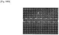
- Figs. 10A to 10D are diagrams illustrating an example of the speckle image obtained in this manner. As illustrated in Figs. 10A to 10D , portions enclosed with frames of alternate long and short dashed lines in all patterns correspond to channels. Figs. 10A and 10B illustrate speckle when the flow of the fluid X is stopped, and Figs. 10C and 10D illustrate the fluid X flowing. Also, Figs. 10A and 10C illustrate that the opening diameter of the iris diaphragm is 12 millimeter, and Figs. 10B and 10D illustrate that the opening diameter is 4 millimeter. It can be observed that speckle patterns and contrast become different according to whether the fluid flows or not or according to the size of the aperture, from the image illustrated in Figs. 10A to 10D .
- the speckle contrast is calculated in the method above with reference to Expression (9).
- the speckle contrast for each size of the aperture can be obtained by obtaining a standard deviation sigma and an average ⁇ I> from the frequency distribution of the luminance gradation obtained by subtracting a value corresponding to a dark current for each pixel with respect to the area in which the illuminance near the center of the channel image is even.
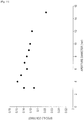
- Fig. 11 is a graph illustrating a relationship between the numerical aperture and the speckle contrast with respect to the speckle images illustrated in Figs. 10A to 10D .
- the speckle contrast is obtained as a maximum value. That is, it is found that the sensitivity and the accuracy become the maximum by setting the numerical aperture of the image forming optical system 3 to be 4 millimeter in order to visualize the flow of the fluid. In this manner, the numerical aperture of the image forming optical system 3 can be controlled so that the speckle contrast becomes the maximum.
- Example 2 a test is performed in the same manner as in Example 1 except for controlling the aperture so that the difference between the speckle contrast and speckle contrast other than that of the fluid X becomes the maximum instead of controlling the aperture so that the speckle contrast becomes the maximum.
- Fig. 12 is a graph illustrating a relationship between the numerical aperture and the difference between the speckle contrast and the speckle contrast other than that of the fluid X with respect to the speckle images illustrated in Figs. 10A to 10D .
- the sensitivity and the accuracy become the maximum by setting the size of the aperture of the image forming optical system 3 to be about 6 millimeter. In this manner, the numerical aperture of the image forming optical system 3 can be controlled.
- a test is performed in the same manner as in Example 1 except for using the image forming optical system 3 illustrated in Fig. 2 instead of the image forming optical system 3 used in Examples 1 and 2.
- an image of the flow is captured by controlling the aperture in real time by the liquid crystal transmission-type spatial optical modulator manufactured by Holoeye photonics installed in substitution for the iris diaphragm.
- the size of the aperture of which a speckle pattern changes from a particle shape to a stripe shape is obtained while the aperture of the spatial optical modulator is controlled, and the image of the flow with the numerical aperture and the shape thereof is captured. Accordingly, the test result which is the same as that in Example 1 can be obtained.
- a test is performed in the same manner as in Examples 1, 2, and 3 except for using the fluid analysis device 11 illustrated in Fig. 8 instead of the fluid analysis device 1 used in Examples 1, 2, and 3.
- the rotating chopper 61 is provided in front of the beam expander 21, and the broad band polarization beam splitter 62 which is valid when the wavelength is in the range of 400 nanometer to 800 nanometer is provided behind the beam expander 21.
- the polarization beam splitter 62 is arranged so as to be penetrated by a laser in the wavelength of 780 nanometer.
- the parallel light from the Xe lamp can pass through the rotating band pass filter 63 in which the blockage of red, green, and blue changes at an even time interval, and be incident to and reflected on the polarization beam splitter 62.
- the rotating chopper 61 and the rotating band pass filter 63 are synchronized, and the same position on the sample surface can be illuminated with red, green, and blue naturally emitted light and a near infrared laser beam at the same time interval.
- the rotating chopper 61 and the rotating band pass filter 63 are synchronized with an imaging camera (the imaging device 41), the images illuminated with the red, green, and blue light and a near infrared laser beam are repeatedly obtained, and the image data is sent to a PC.
- the spatial optical modulator 34 which is the same as in Example 3 is provided.
- the numerical aperture is set to be great, and when the sensitivity and the accuracy of the flow in the speckle image are necessary, the numerical aperture is set so that the sensitivity and the accuracy of the flow detection in the method of Example 2 become high, and this aperture control is repeated. Accordingly, a good bright field image and a good image of a flow in the same observation position can be simultaneously observed in real time.
- the Xe lamp is used as the incoherent light irradiation unit 6, but a visible light laser with sufficiently low coherency may be used.
- Example 4 it is found that optimum sensitivity, accuracy, resolution, and a focal depth are obtained when the image forming optical system is used together with the bright field image, the fluorescence image, and the like.
Landscapes
- Health & Medical Sciences (AREA)
- Life Sciences & Earth Sciences (AREA)
- Surgery (AREA)
- Heart & Thoracic Surgery (AREA)
- Molecular Biology (AREA)
- Veterinary Medicine (AREA)
- Biophysics (AREA)
- Pathology (AREA)
- Engineering & Computer Science (AREA)
- Biomedical Technology (AREA)
- Public Health (AREA)
- Medical Informatics (AREA)
- Physics & Mathematics (AREA)
- General Health & Medical Sciences (AREA)
- Animal Behavior & Ethology (AREA)
- Nuclear Medicine, Radiotherapy & Molecular Imaging (AREA)
- Radiology & Medical Imaging (AREA)
- Optics & Photonics (AREA)
- Hematology (AREA)
- Cardiology (AREA)
- Physiology (AREA)
- Investigating Or Analysing Materials By Optical Means (AREA)
- Measuring Pulse, Heart Rate, Blood Pressure Or Blood Flow (AREA)
Applications Claiming Priority (3)
| Application Number | Priority Date | Filing Date | Title |
|---|---|---|---|
| JP2014112436 | 2014-05-30 | ||
| JP2014260054A JP6394367B2 (ja) | 2014-05-30 | 2014-12-24 | 流体分析装置、流体分析方法、プログラム及び流体分析システム |
| PCT/JP2015/002521 WO2015182065A1 (en) | 2014-05-30 | 2015-05-20 | Imaging apparatus, imaging method and medical imaging system |
Publications (2)
| Publication Number | Publication Date |
|---|---|
| EP3148411A1 EP3148411A1 (en) | 2017-04-05 |
| EP3148411B1 true EP3148411B1 (en) | 2020-07-22 |
Family
ID=53404827
Family Applications (1)
| Application Number | Title | Priority Date | Filing Date |
|---|---|---|---|
| EP15729582.5A Not-in-force EP3148411B1 (en) | 2014-05-30 | 2015-05-20 | Imaging apparatus, imaging method and medical imaging system |
Country Status (5)
| Country | Link |
|---|---|
| US (1) | US20170188853A1 (enExample) |
| EP (1) | EP3148411B1 (enExample) |
| JP (1) | JP6394367B2 (enExample) |
| CN (1) | CN106413543B (enExample) |
| WO (1) | WO2015182065A1 (enExample) |
Families Citing this family (27)
| Publication number | Priority date | Publication date | Assignee | Title |
|---|---|---|---|---|
| US10652444B2 (en) | 2012-10-30 | 2020-05-12 | California Institute Of Technology | Multiplexed Fourier ptychography imaging systems and methods |
| US10679763B2 (en) | 2012-10-30 | 2020-06-09 | California Institute Of Technology | Fourier ptychographic imaging systems, devices, and methods |
| US9864184B2 (en) | 2012-10-30 | 2018-01-09 | California Institute Of Technology | Embedded pupil function recovery for fourier ptychographic imaging devices |
| WO2015017730A1 (en) | 2013-07-31 | 2015-02-05 | California Institute Of Technoloby | Aperture scanning fourier ptychographic imaging |
| CN110082900B (zh) | 2013-08-22 | 2022-05-13 | 加州理工学院 | 可变照明傅立叶重叠关联成像设备、系统以及方法 |
| US11468557B2 (en) | 2014-03-13 | 2022-10-11 | California Institute Of Technology | Free orientation fourier camera |
| CN107111118B (zh) | 2014-12-22 | 2019-12-10 | 加州理工学院 | 用于厚样本的epi照明傅立叶重叠关联成像 |
| AU2016209275A1 (en) | 2015-01-21 | 2017-06-29 | California Institute Of Technology | Fourier ptychographic tomography |
| AU2016211635A1 (en) | 2015-01-26 | 2017-06-29 | California Institute Of Technology | Multi-well fourier ptychographic and fluorescence imaging |
| JP6798511B2 (ja) * | 2016-02-18 | 2020-12-09 | ソニー株式会社 | 撮像装置及び撮像システム |
| US20190293554A1 (en) * | 2016-03-28 | 2019-09-26 | Sony Corporation | Imaging apparatus and imaging method |
| EP3440997B1 (en) * | 2016-04-05 | 2020-11-25 | Sony Corporation | Speckle measurement device and speckle measurement method |
| US10690904B2 (en) * | 2016-04-12 | 2020-06-23 | Stryker Corporation | Multiple imaging modality light source |
| US11092795B2 (en) | 2016-06-10 | 2021-08-17 | California Institute Of Technology | Systems and methods for coded-aperture-based correction of aberration obtained from Fourier ptychography |
| US10568507B2 (en) * | 2016-06-10 | 2020-02-25 | California Institute Of Technology | Pupil ptychography methods and systems |
| JP6999656B2 (ja) | 2017-05-02 | 2022-01-18 | ソニーグループ株式会社 | 流速測定方法、流速測定装置及びプログラム |
| JP7156275B2 (ja) * | 2017-05-16 | 2022-10-19 | ソニーグループ株式会社 | 制御装置、制御方法、及びプログラム |
| WO2019090149A1 (en) | 2017-11-03 | 2019-05-09 | California Institute Of Technology | Parallel digital imaging acquisition and restoration methods and systems |
| JP2020163037A (ja) * | 2019-03-29 | 2020-10-08 | ソニー株式会社 | 医療システム、情報処理装置及び情報処理方法 |
| US11194074B2 (en) * | 2019-08-30 | 2021-12-07 | Baker Hughes Oilfield Operations Llc | Systems and methods for downhole imaging through a scattering medium |
| CN111012325B (zh) * | 2019-12-05 | 2022-07-29 | 华中科技大学苏州脑空间信息研究院 | 一种精准光调控系统及光调控方法 |
| IL294563B1 (en) | 2020-01-14 | 2026-04-01 | Pxe Computational Imaging Ltd | System and method for optical imaging and measurement of objects |
| US12198300B2 (en) | 2021-02-25 | 2025-01-14 | California Institute Of Technology | Computational refocusing-assisted deep learning |
| JP7499973B2 (ja) * | 2021-07-29 | 2024-06-14 | 三菱電機株式会社 | 撮像システム及び撮像方法 |
| CN118765377A (zh) * | 2021-12-23 | 2024-10-11 | 雷迪奥米特医学公司 | 具有自适应光圈设备的生物流体分析仪 |
| JP2025034464A (ja) * | 2023-08-31 | 2025-03-13 | 株式会社Screenホールディングス | 観察装置 |
| EP4566522A1 (en) * | 2023-12-08 | 2025-06-11 | Stichting IMEC Nederland | Device and method for analyzing a speckle pattern from biological tissue |
Family Cites Families (14)
| Publication number | Priority date | Publication date | Assignee | Title |
|---|---|---|---|---|
| JPH02232031A (ja) * | 1989-03-06 | 1990-09-14 | Kowa Co | 眼科診断方法 |
| JPH02232028A (ja) * | 1989-03-06 | 1990-09-14 | Kowa Co | 眼科診断装置 |
| JPH02231673A (ja) * | 1989-03-06 | 1990-09-13 | Kowa Co | 相関関数の評価方法 |
| US7113817B1 (en) * | 2001-10-04 | 2006-09-26 | Wintec, Llc | Optical imaging of blood circulation velocities |
| EP2166934A4 (en) * | 2007-07-06 | 2012-10-17 | Ind Res Ltd | ENHANCED LASER GRANULATED IMAGING SYSTEMS AND METHODS |
| JP5087771B2 (ja) | 2007-12-04 | 2012-12-05 | 富士フイルム株式会社 | 撮像システム、内視鏡システム、およびプログラム |
| JP5171564B2 (ja) * | 2008-11-14 | 2013-03-27 | キヤノン株式会社 | 音響光学トモグラフィー測定装置および測定方法 |
| GB0921477D0 (en) * | 2009-12-08 | 2010-01-20 | Moor Instr Ltd | Apparatus for measuring blood parameters |
| EP2760338B1 (en) * | 2011-09-26 | 2018-08-22 | The Johns Hopkins University | Anisotropic processing of laser speckle images |
| EP2809225B1 (en) * | 2012-02-03 | 2017-04-05 | Oregon Health & Science University | In vivo optical flow imaging |
| US9848787B2 (en) * | 2012-02-07 | 2017-12-26 | Laser Associated Sciences, Inc. | Perfusion assessment using transmission laser speckle imaging |
| EP2861935B1 (en) * | 2012-06-13 | 2016-02-10 | Koninklijke Philips N.V. | Determining a propagation velocity for a surface wave |
| US20150286341A1 (en) * | 2012-11-21 | 2015-10-08 | The Board Of Trustees Of The Leland Stanford Junior University | multi-touch ultrasonic touch screen |
| CN104287713B (zh) * | 2013-06-13 | 2016-04-13 | 上海理工大学 | 一种快速激光散斑血流成像方法 |
-
2014
- 2014-12-24 JP JP2014260054A patent/JP6394367B2/ja not_active Expired - Fee Related
-
2015
- 2015-05-20 US US15/313,573 patent/US20170188853A1/en not_active Abandoned
- 2015-05-20 WO PCT/JP2015/002521 patent/WO2015182065A1/en not_active Ceased
- 2015-05-20 CN CN201580026353.1A patent/CN106413543B/zh not_active Expired - Fee Related
- 2015-05-20 EP EP15729582.5A patent/EP3148411B1/en not_active Not-in-force
Non-Patent Citations (1)
| Title |
|---|
| None * |
Also Published As
| Publication number | Publication date |
|---|---|
| JP2016005525A (ja) | 2016-01-14 |
| US20170188853A1 (en) | 2017-07-06 |
| EP3148411A1 (en) | 2017-04-05 |
| CN106413543B (zh) | 2020-02-18 |
| JP6394367B2 (ja) | 2018-09-26 |
| WO2015182065A1 (en) | 2015-12-03 |
| CN106413543A (zh) | 2017-02-15 |
Similar Documents
| Publication | Publication Date | Title |
|---|---|---|
| EP3148411B1 (en) | Imaging apparatus, imaging method and medical imaging system | |
| US20160157736A1 (en) | System and Methods for Assessment of Relative Fluid Flow Using Laser Speckle Imaging | |
| US9645070B2 (en) | Nanoparticle analyzer | |
| US20210250479A1 (en) | Ballistic light modulations for image enhancement through fog | |
| US20190045112A1 (en) | Imaging apparatus, imaging method, and imaging system | |
| KR20210027404A (ko) | 복강경 검사에서 혈류 및 조직 관류의 무염색 가시화를 위한 방법 및 시스템 | |
| JP2016526185A (ja) | 構造化照明を用いた組織試料の顕微鏡観察 | |
| WO2017168984A1 (ja) | 撮像装置、撮像方法 | |
| US20180302542A1 (en) | Image capturing apparatus, image capturing method, and storage medium | |
| US20190099089A1 (en) | Image analysis apparatus and image analysis method | |
| EP3416366A1 (en) | Image pickup apparatus, image pickup method, and image pickup system | |
| TW201827914A (zh) | 觀察裝置及觀察方法 | |
| US11874224B2 (en) | Sample observation device and sample observation method | |
| JP6948407B2 (ja) | 表面トポロジおよび関連する色を決定するための装置および方法 | |
| Cavalcanti et al. | Smartphone‐based spectral imaging otoscope: System development and preliminary study for evaluation of its potential as a mobile diagnostic tool | |
| WO2018211982A1 (ja) | 画像処理装置および方法、並びに画像処理システム | |
| JP2019080804A5 (enExample) | ||
| JP6887599B2 (ja) | コロイド粒子の成長キネティクスまたは分解キネティクスの測定のための装置および方法 | |
| US11710236B1 (en) | Variable exposure portable perfusion monitor | |
| JP7659895B2 (ja) | 試料観察方法、試料観察装置、及び顕微鏡 | |
| JP2021040731A (ja) | 均一照射モジュール | |
| WO2023200692A1 (en) | Variable exposure portable perfusion monitor | |
| Akashi et al. | Scattering tomography using ellipsoidal mirror | |
| WO2026035545A1 (en) | Multi-segment darkfield imaging | |
| AU2024358861A1 (en) | Self-calibrating devices, systems, and methods of measuring corneal topography |
Legal Events
| Date | Code | Title | Description |
|---|---|---|---|
| STAA | Information on the status of an ep patent application or granted ep patent |
Free format text: STATUS: THE INTERNATIONAL PUBLICATION HAS BEEN MADE |
|
| PUAI | Public reference made under article 153(3) epc to a published international application that has entered the european phase |
Free format text: ORIGINAL CODE: 0009012 |
|
| STAA | Information on the status of an ep patent application or granted ep patent |
Free format text: STATUS: REQUEST FOR EXAMINATION WAS MADE |
|
| 17P | Request for examination filed |
Effective date: 20161123 |
|
| AK | Designated contracting states |
Kind code of ref document: A1 Designated state(s): AL AT BE BG CH CY CZ DE DK EE ES FI FR GB GR HR HU IE IS IT LI LT LU LV MC MK MT NL NO PL PT RO RS SE SI SK SM TR |
|
| AX | Request for extension of the european patent |
Extension state: BA ME |
|
| DAV | Request for validation of the european patent (deleted) | ||
| DAX | Request for extension of the european patent (deleted) | ||
| GRAP | Despatch of communication of intention to grant a patent |
Free format text: ORIGINAL CODE: EPIDOSNIGR1 |
|
| STAA | Information on the status of an ep patent application or granted ep patent |
Free format text: STATUS: GRANT OF PATENT IS INTENDED |
|
| INTG | Intention to grant announced |
Effective date: 20200221 |
|
| GRAS | Grant fee paid |
Free format text: ORIGINAL CODE: EPIDOSNIGR3 |
|
| GRAA | (expected) grant |
Free format text: ORIGINAL CODE: 0009210 |
|
| STAA | Information on the status of an ep patent application or granted ep patent |
Free format text: STATUS: THE PATENT HAS BEEN GRANTED |
|
| AK | Designated contracting states |
Kind code of ref document: B1 Designated state(s): AL AT BE BG CH CY CZ DE DK EE ES FI FR GB GR HR HU IE IS IT LI LT LU LV MC MK MT NL NO PL PT RO RS SE SI SK SM TR |
|
| REG | Reference to a national code |
Ref country code: GB Ref legal event code: FG4D |
|
| REG | Reference to a national code |
Ref country code: CH Ref legal event code: EP |
|
| REG | Reference to a national code |
Ref country code: DE Ref legal event code: R096 Ref document number: 602015056130 Country of ref document: DE |
|
| REG | Reference to a national code |
Ref country code: AT Ref legal event code: REF Ref document number: 1292575 Country of ref document: AT Kind code of ref document: T Effective date: 20200815 |
|
| REG | Reference to a national code |
Ref country code: IE Ref legal event code: FG4D |
|
| REG | Reference to a national code |
Ref country code: LT Ref legal event code: MG4D |
|
| REG | Reference to a national code |
Ref country code: AT Ref legal event code: MK05 Ref document number: 1292575 Country of ref document: AT Kind code of ref document: T Effective date: 20200722 |
|
| PG25 | Lapsed in a contracting state [announced via postgrant information from national office to epo] |
Ref country code: NO Free format text: LAPSE BECAUSE OF FAILURE TO SUBMIT A TRANSLATION OF THE DESCRIPTION OR TO PAY THE FEE WITHIN THE PRESCRIBED TIME-LIMIT Effective date: 20201022 Ref country code: GR Free format text: LAPSE BECAUSE OF FAILURE TO SUBMIT A TRANSLATION OF THE DESCRIPTION OR TO PAY THE FEE WITHIN THE PRESCRIBED TIME-LIMIT Effective date: 20201023 Ref country code: SE Free format text: LAPSE BECAUSE OF FAILURE TO SUBMIT A TRANSLATION OF THE DESCRIPTION OR TO PAY THE FEE WITHIN THE PRESCRIBED TIME-LIMIT Effective date: 20200722 Ref country code: FI Free format text: LAPSE BECAUSE OF FAILURE TO SUBMIT A TRANSLATION OF THE DESCRIPTION OR TO PAY THE FEE WITHIN THE PRESCRIBED TIME-LIMIT Effective date: 20200722 Ref country code: LT Free format text: LAPSE BECAUSE OF FAILURE TO SUBMIT A TRANSLATION OF THE DESCRIPTION OR TO PAY THE FEE WITHIN THE PRESCRIBED TIME-LIMIT Effective date: 20200722 Ref country code: HR Free format text: LAPSE BECAUSE OF FAILURE TO SUBMIT A TRANSLATION OF THE DESCRIPTION OR TO PAY THE FEE WITHIN THE PRESCRIBED TIME-LIMIT Effective date: 20200722 Ref country code: PT Free format text: LAPSE BECAUSE OF FAILURE TO SUBMIT A TRANSLATION OF THE DESCRIPTION OR TO PAY THE FEE WITHIN THE PRESCRIBED TIME-LIMIT Effective date: 20201123 Ref country code: AT Free format text: LAPSE BECAUSE OF FAILURE TO SUBMIT A TRANSLATION OF THE DESCRIPTION OR TO PAY THE FEE WITHIN THE PRESCRIBED TIME-LIMIT Effective date: 20200722 Ref country code: BG Free format text: LAPSE BECAUSE OF FAILURE TO SUBMIT A TRANSLATION OF THE DESCRIPTION OR TO PAY THE FEE WITHIN THE PRESCRIBED TIME-LIMIT Effective date: 20201022 Ref country code: ES Free format text: LAPSE BECAUSE OF FAILURE TO SUBMIT A TRANSLATION OF THE DESCRIPTION OR TO PAY THE FEE WITHIN THE PRESCRIBED TIME-LIMIT Effective date: 20200722 |
|
| PG25 | Lapsed in a contracting state [announced via postgrant information from national office to epo] |
Ref country code: PL Free format text: LAPSE BECAUSE OF FAILURE TO SUBMIT A TRANSLATION OF THE DESCRIPTION OR TO PAY THE FEE WITHIN THE PRESCRIBED TIME-LIMIT Effective date: 20200722 Ref country code: RS Free format text: LAPSE BECAUSE OF FAILURE TO SUBMIT A TRANSLATION OF THE DESCRIPTION OR TO PAY THE FEE WITHIN THE PRESCRIBED TIME-LIMIT Effective date: 20200722 Ref country code: LV Free format text: LAPSE BECAUSE OF FAILURE TO SUBMIT A TRANSLATION OF THE DESCRIPTION OR TO PAY THE FEE WITHIN THE PRESCRIBED TIME-LIMIT Effective date: 20200722 Ref country code: IS Free format text: LAPSE BECAUSE OF FAILURE TO SUBMIT A TRANSLATION OF THE DESCRIPTION OR TO PAY THE FEE WITHIN THE PRESCRIBED TIME-LIMIT Effective date: 20201122 |
|
| PG25 | Lapsed in a contracting state [announced via postgrant information from national office to epo] |
Ref country code: NL Free format text: LAPSE BECAUSE OF FAILURE TO SUBMIT A TRANSLATION OF THE DESCRIPTION OR TO PAY THE FEE WITHIN THE PRESCRIBED TIME-LIMIT Effective date: 20200722 |
|
| REG | Reference to a national code |
Ref country code: DE Ref legal event code: R097 Ref document number: 602015056130 Country of ref document: DE |
|
| PG25 | Lapsed in a contracting state [announced via postgrant information from national office to epo] |
Ref country code: IT Free format text: LAPSE BECAUSE OF FAILURE TO SUBMIT A TRANSLATION OF THE DESCRIPTION OR TO PAY THE FEE WITHIN THE PRESCRIBED TIME-LIMIT Effective date: 20200722 Ref country code: DK Free format text: LAPSE BECAUSE OF FAILURE TO SUBMIT A TRANSLATION OF THE DESCRIPTION OR TO PAY THE FEE WITHIN THE PRESCRIBED TIME-LIMIT Effective date: 20200722 Ref country code: CZ Free format text: LAPSE BECAUSE OF FAILURE TO SUBMIT A TRANSLATION OF THE DESCRIPTION OR TO PAY THE FEE WITHIN THE PRESCRIBED TIME-LIMIT Effective date: 20200722 Ref country code: EE Free format text: LAPSE BECAUSE OF FAILURE TO SUBMIT A TRANSLATION OF THE DESCRIPTION OR TO PAY THE FEE WITHIN THE PRESCRIBED TIME-LIMIT Effective date: 20200722 Ref country code: SM Free format text: LAPSE BECAUSE OF FAILURE TO SUBMIT A TRANSLATION OF THE DESCRIPTION OR TO PAY THE FEE WITHIN THE PRESCRIBED TIME-LIMIT Effective date: 20200722 Ref country code: RO Free format text: LAPSE BECAUSE OF FAILURE TO SUBMIT A TRANSLATION OF THE DESCRIPTION OR TO PAY THE FEE WITHIN THE PRESCRIBED TIME-LIMIT Effective date: 20200722 |
|
| PLBE | No opposition filed within time limit |
Free format text: ORIGINAL CODE: 0009261 |
|
| STAA | Information on the status of an ep patent application or granted ep patent |
Free format text: STATUS: NO OPPOSITION FILED WITHIN TIME LIMIT |
|
| PG25 | Lapsed in a contracting state [announced via postgrant information from national office to epo] |
Ref country code: AL Free format text: LAPSE BECAUSE OF FAILURE TO SUBMIT A TRANSLATION OF THE DESCRIPTION OR TO PAY THE FEE WITHIN THE PRESCRIBED TIME-LIMIT Effective date: 20200722 |
|
| 26N | No opposition filed |
Effective date: 20210423 |
|
| PG25 | Lapsed in a contracting state [announced via postgrant information from national office to epo] |
Ref country code: SK Free format text: LAPSE BECAUSE OF FAILURE TO SUBMIT A TRANSLATION OF THE DESCRIPTION OR TO PAY THE FEE WITHIN THE PRESCRIBED TIME-LIMIT Effective date: 20200722 |
|
| PG25 | Lapsed in a contracting state [announced via postgrant information from national office to epo] |
Ref country code: SI Free format text: LAPSE BECAUSE OF FAILURE TO SUBMIT A TRANSLATION OF THE DESCRIPTION OR TO PAY THE FEE WITHIN THE PRESCRIBED TIME-LIMIT Effective date: 20200722 |
|
| REG | Reference to a national code |
Ref country code: NL Ref legal event code: MP Effective date: 20200722 |
|
| REG | Reference to a national code |
Ref country code: CH Ref legal event code: PL |
|
| PG25 | Lapsed in a contracting state [announced via postgrant information from national office to epo] |
Ref country code: CH Free format text: LAPSE BECAUSE OF NON-PAYMENT OF DUE FEES Effective date: 20210531 Ref country code: LI Free format text: LAPSE BECAUSE OF NON-PAYMENT OF DUE FEES Effective date: 20210531 Ref country code: LU Free format text: LAPSE BECAUSE OF NON-PAYMENT OF DUE FEES Effective date: 20210520 Ref country code: MC Free format text: LAPSE BECAUSE OF FAILURE TO SUBMIT A TRANSLATION OF THE DESCRIPTION OR TO PAY THE FEE WITHIN THE PRESCRIBED TIME-LIMIT Effective date: 20200722 |
|
| REG | Reference to a national code |
Ref country code: BE Ref legal event code: MM Effective date: 20210531 |
|
| PG25 | Lapsed in a contracting state [announced via postgrant information from national office to epo] |
Ref country code: IE Free format text: LAPSE BECAUSE OF NON-PAYMENT OF DUE FEES Effective date: 20210520 |
|
| PG25 | Lapsed in a contracting state [announced via postgrant information from national office to epo] |
Ref country code: FR Free format text: LAPSE BECAUSE OF NON-PAYMENT OF DUE FEES Effective date: 20210531 |
|
| PG25 | Lapsed in a contracting state [announced via postgrant information from national office to epo] |
Ref country code: BE Free format text: LAPSE BECAUSE OF NON-PAYMENT OF DUE FEES Effective date: 20210531 |
|
| PGFP | Annual fee paid to national office [announced via postgrant information from national office to epo] |
Ref country code: GB Payment date: 20220426 Year of fee payment: 8 Ref country code: DE Payment date: 20220420 Year of fee payment: 8 |
|
| PG25 | Lapsed in a contracting state [announced via postgrant information from national office to epo] |
Ref country code: HU Free format text: LAPSE BECAUSE OF FAILURE TO SUBMIT A TRANSLATION OF THE DESCRIPTION OR TO PAY THE FEE WITHIN THE PRESCRIBED TIME-LIMIT; INVALID AB INITIO Effective date: 20150520 |
|
| PG25 | Lapsed in a contracting state [announced via postgrant information from national office to epo] |
Ref country code: CY Free format text: LAPSE BECAUSE OF FAILURE TO SUBMIT A TRANSLATION OF THE DESCRIPTION OR TO PAY THE FEE WITHIN THE PRESCRIBED TIME-LIMIT Effective date: 20200722 |
|
| REG | Reference to a national code |
Ref country code: DE Ref legal event code: R119 Ref document number: 602015056130 Country of ref document: DE |
|
| GBPC | Gb: european patent ceased through non-payment of renewal fee |
Effective date: 20230520 |
|
| PG25 | Lapsed in a contracting state [announced via postgrant information from national office to epo] |
Ref country code: MK Free format text: LAPSE BECAUSE OF FAILURE TO SUBMIT A TRANSLATION OF THE DESCRIPTION OR TO PAY THE FEE WITHIN THE PRESCRIBED TIME-LIMIT Effective date: 20200722 Ref country code: DE Free format text: LAPSE BECAUSE OF NON-PAYMENT OF DUE FEES Effective date: 20231201 Ref country code: GB Free format text: LAPSE BECAUSE OF NON-PAYMENT OF DUE FEES Effective date: 20230520 |
|
| PG25 | Lapsed in a contracting state [announced via postgrant information from national office to epo] |
Ref country code: TR Free format text: LAPSE BECAUSE OF FAILURE TO SUBMIT A TRANSLATION OF THE DESCRIPTION OR TO PAY THE FEE WITHIN THE PRESCRIBED TIME-LIMIT Effective date: 20200722 |
|
| PG25 | Lapsed in a contracting state [announced via postgrant information from national office to epo] |
Ref country code: MT Free format text: LAPSE BECAUSE OF FAILURE TO SUBMIT A TRANSLATION OF THE DESCRIPTION OR TO PAY THE FEE WITHIN THE PRESCRIBED TIME-LIMIT Effective date: 20200722 |