EP3148039A1 - Schnellladeverfahren, stromquellenadapter und mobiles endgerät - Google Patents
Schnellladeverfahren, stromquellenadapter und mobiles endgerät Download PDFInfo
- Publication number
- EP3148039A1 EP3148039A1 EP15859023.2A EP15859023A EP3148039A1 EP 3148039 A1 EP3148039 A1 EP 3148039A1 EP 15859023 A EP15859023 A EP 15859023A EP 3148039 A1 EP3148039 A1 EP 3148039A1
- Authority
- EP
- European Patent Office
- Prior art keywords
- mobile terminal
- power adapter
- charging
- instruction
- charging mode
- Prior art date
- Legal status (The legal status is an assumption and is not a legal conclusion. Google has not performed a legal analysis and makes no representation as to the accuracy of the status listed.)
- Pending
Links
Images
Classifications
-
- H—ELECTRICITY
- H02—GENERATION; CONVERSION OR DISTRIBUTION OF ELECTRIC POWER
- H02J—CIRCUIT ARRANGEMENTS OR SYSTEMS FOR SUPPLYING OR DISTRIBUTING ELECTRIC POWER; SYSTEMS FOR STORING ELECTRIC ENERGY
- H02J7/00—Circuit arrangements for charging or depolarising batteries or for supplying loads from batteries
- H02J7/007—Regulation of charging or discharging current or voltage
-
- H—ELECTRICITY
- H02—GENERATION; CONVERSION OR DISTRIBUTION OF ELECTRIC POWER
- H02J—CIRCUIT ARRANGEMENTS OR SYSTEMS FOR SUPPLYING OR DISTRIBUTING ELECTRIC POWER; SYSTEMS FOR STORING ELECTRIC ENERGY
- H02J7/00—Circuit arrangements for charging or depolarising batteries or for supplying loads from batteries
-
- G—PHYSICS
- G01—MEASURING; TESTING
- G01R—MEASURING ELECTRIC VARIABLES; MEASURING MAGNETIC VARIABLES
- G01R31/00—Arrangements for testing electric properties; Arrangements for locating electric faults; Arrangements for electrical testing characterised by what is being tested not provided for elsewhere
- G01R31/50—Testing of electric apparatus, lines, cables or components for short-circuits, continuity, leakage current or incorrect line connections
- G01R31/66—Testing of connections, e.g. of plugs or non-disconnectable joints
- G01R31/67—Testing the correctness of wire connections in electric apparatus or circuits
-
- G—PHYSICS
- G06—COMPUTING; CALCULATING OR COUNTING
- G06F—ELECTRIC DIGITAL DATA PROCESSING
- G06F1/00—Details not covered by groups G06F3/00 - G06F13/00 and G06F21/00
- G06F1/16—Constructional details or arrangements
- G06F1/20—Cooling means
- G06F1/206—Cooling means comprising thermal management
-
- G—PHYSICS
- G06—COMPUTING; CALCULATING OR COUNTING
- G06F—ELECTRIC DIGITAL DATA PROCESSING
- G06F1/00—Details not covered by groups G06F3/00 - G06F13/00 and G06F21/00
- G06F1/26—Power supply means, e.g. regulation thereof
-
- H—ELECTRICITY
- H02—GENERATION; CONVERSION OR DISTRIBUTION OF ELECTRIC POWER
- H02J—CIRCUIT ARRANGEMENTS OR SYSTEMS FOR SUPPLYING OR DISTRIBUTING ELECTRIC POWER; SYSTEMS FOR STORING ELECTRIC ENERGY
- H02J7/00—Circuit arrangements for charging or depolarising batteries or for supplying loads from batteries
- H02J7/0029—Circuit arrangements for charging or depolarising batteries or for supplying loads from batteries with safety or protection devices or circuits
- H02J7/0036—Circuit arrangements for charging or depolarising batteries or for supplying loads from batteries with safety or protection devices or circuits using connection detecting circuits
-
- H—ELECTRICITY
- H02—GENERATION; CONVERSION OR DISTRIBUTION OF ELECTRIC POWER
- H02J—CIRCUIT ARRANGEMENTS OR SYSTEMS FOR SUPPLYING OR DISTRIBUTING ELECTRIC POWER; SYSTEMS FOR STORING ELECTRIC ENERGY
- H02J7/00—Circuit arrangements for charging or depolarising batteries or for supplying loads from batteries
- H02J7/0042—Circuit arrangements for charging or depolarising batteries or for supplying loads from batteries characterised by the mechanical construction
- H02J7/0044—Circuit arrangements for charging or depolarising batteries or for supplying loads from batteries characterised by the mechanical construction specially adapted for holding portable devices containing batteries
-
- H—ELECTRICITY
- H02—GENERATION; CONVERSION OR DISTRIBUTION OF ELECTRIC POWER
- H02J—CIRCUIT ARRANGEMENTS OR SYSTEMS FOR SUPPLYING OR DISTRIBUTING ELECTRIC POWER; SYSTEMS FOR STORING ELECTRIC ENERGY
- H02J7/00—Circuit arrangements for charging or depolarising batteries or for supplying loads from batteries
- H02J7/0042—Circuit arrangements for charging or depolarising batteries or for supplying loads from batteries characterised by the mechanical construction
- H02J7/0045—Circuit arrangements for charging or depolarising batteries or for supplying loads from batteries characterised by the mechanical construction concerning the insertion or the connection of the batteries
-
- H—ELECTRICITY
- H02—GENERATION; CONVERSION OR DISTRIBUTION OF ELECTRIC POWER
- H02J—CIRCUIT ARRANGEMENTS OR SYSTEMS FOR SUPPLYING OR DISTRIBUTING ELECTRIC POWER; SYSTEMS FOR STORING ELECTRIC ENERGY
- H02J7/00—Circuit arrangements for charging or depolarising batteries or for supplying loads from batteries
- H02J7/02—Circuit arrangements for charging or depolarising batteries or for supplying loads from batteries for charging batteries from ac mains by converters
- H02J7/04—Regulation of charging current or voltage
-
- H—ELECTRICITY
- H02—GENERATION; CONVERSION OR DISTRIBUTION OF ELECTRIC POWER
- H02J—CIRCUIT ARRANGEMENTS OR SYSTEMS FOR SUPPLYING OR DISTRIBUTING ELECTRIC POWER; SYSTEMS FOR STORING ELECTRIC ENERGY
- H02J7/00—Circuit arrangements for charging or depolarising batteries or for supplying loads from batteries
- H02J7/00032—Circuit arrangements for charging or depolarising batteries or for supplying loads from batteries characterised by data exchange
- H02J7/00034—Charger exchanging data with an electronic device, i.e. telephone, whose internal battery is under charge
-
- H—ELECTRICITY
- H02—GENERATION; CONVERSION OR DISTRIBUTION OF ELECTRIC POWER
- H02J—CIRCUIT ARRANGEMENTS OR SYSTEMS FOR SUPPLYING OR DISTRIBUTING ELECTRIC POWER; SYSTEMS FOR STORING ELECTRIC ENERGY
- H02J7/00—Circuit arrangements for charging or depolarising batteries or for supplying loads from batteries
- H02J7/00032—Circuit arrangements for charging or depolarising batteries or for supplying loads from batteries characterised by data exchange
- H02J7/00045—Authentication, i.e. circuits for checking compatibility between one component, e.g. a battery or a battery charger, and another component, e.g. a power source
Definitions
- the present disclosure relates to the field of battery charging, and more particularly, to a fast charging method, a power adapter and a mobile terminal using the same.
- Embodiments of the present disclosure provide a fast charging method, a power adapter and a mobile terminal, in order to improve the security of fast charging process.
- a first aspect provides a fast charging method, wherein the method is executed by a mobile terminal, the mobile terminal is coupled to a power adapter via a USB (Universal Serial Bus) interface; a power line located in the USB interface is configured for charging the mobile terminal, a data line located in the USB interface is configured for establishing a communication between the power adapter and the mobile terminal; the mobile terminal supports an common charging mode and a fast charging mode, and a charging current under the fast charging mode is greater than a charging current under the common charging mode; the method comprises: sending, by the mobile terminal, a first instruction to the power adapter through the data line in the USB interface, the first instruction being configured for instructing the power adapter to start the fast charging mode; and receiving, by the mobile terminal, a charging current corresponding to the fast charging mode from the power adapter, so as to charge a battery in the mobile terminal.
- a USB Universal Serial Bus
- the method before receiving, by the mobile terminal, the charging current corresponding to the fast charging mode from the power adapter, so as to charge the battery in the mobile terminal, the method further comprises: sending, by the mobile terminal, a second instruction to the power adapter through the data line in the USB interface, the second instruction being configured for indicating a charging voltage corresponding to the fast charging mode.
- the method before receiving, by the mobile terminal, the charging current corresponding to the fast charging mode from the power adapter, so as to charge the battery in the mobile terminal, the method further comprises: sending, by the mobile terminal, a third instruction to the power adapter through the data line in the USB interface, the third instruction being configured for indicating the charging current corresponding to the fast charging mode.
- the method further comprises: sending, by the mobile terminal, a fourth instruction to the power adapter through the data line in the USB interface during a period of charging the mobile terminal by the power adapter under the fast charging mode, the fourth instruction being configured for indicating a current voltage of the battery in the mobile terminal such that the power adapter adjusts the charging current based on the current voltage of the battery, or determines whether a connection to the USB interface is abnormal based on the charging voltage from the power adapter and the current voltage of the battery.
- a second aspect provides a fast charging method, wherein the method is executed by a power adapter, the power adapter is coupled to a mobile terminal via a USB (Universal Serial Bus) interface; a power line located in the USB interface is configured for charging the mobile terminal by the power adapter, a data line located in the USB interface is configured for establishing a communication between the power adapter and the mobile terminal; the mobile terminal supports an common charging mode and a fast charging mode, and a charging current under the fast charging mode is greater than a charging current under the common charging mode; the method comprises: receiving, by the power adapter, a first instruction sent by the mobile terminal through the data line in the USB interface, the first instruction being configured for instructing the power adapter to start the fast charging mode; and adjusting, by the power adapter, the charging current to a current corresponding to the fast charging mode, to charge the mobile terminal.
- a USB Universal Serial Bus
- the method before adjusting, by the power adapter, the charging current to the current corresponding to the fast charging mode, to charge the mobile terminal, further comprises: receiving, by the power adapter, a second instruction sent by the mobile terminal through the data line in the USB interface, the second instruction being configured for indicating a charging voltage corresponding to the fast charging mode.
- the method before adjusting, by the power adapter, the charging current to the current corresponding to the fast charging mode, to charge the mobile terminal, further comprises: receiving, by the power adapter, a third instruction sent by the mobile terminal through the data line in the USB interface, the third instruction being configured for indicating the charging current corresponding to the fast charging mode.
- the method further comprises: receiving, by the power adapter, a fourth instruction sent by the mobile terminal through the data line in the USB interface during a period of charging the mobile terminal by the power adapter under the fast charging mode, the fourth instruction being configured for indicating a current voltage of the battery in the mobile terminal; and adjusting, by the power adapter, the charging current based on the current voltage of the battery in the mobile terminal.
- adjusting, by the power adapter, the charging current based on the current voltage of the battery in the mobile terminal comprises: adjusting, by the power adapter, the charging current of the power adapter to the charging current corresponding to the current voltage of the battery, based on the current voltage of the battery, and the preset correspondence between the battery voltage and the charging current.
- the method further comprises: receiving, by the power adapter, a fourth instruction sent by the mobile terminal through the data line in the USB interface during a period of charging the mobile terminal by the power adapter under the fast charging mode, the fourth instruction being configured for indicating a current voltage of the battery in the mobile terminal; and determining, by the power adapter, whether a connection to the USB interface is abnormal based on the charging voltage from the power adapter and the current voltage of the battery.
- the third aspect provides a mobile terminal, wherein the mobile terminal is configured for coupling with a power adapter via a USB (Universal Serial Bus) interface; a power line located in the USB interface is configured for charging the mobile terminal, a data line located in the USB interface is configured for establishing a communication between the power adapter and the mobile terminal; the mobile terminal supports an common charging mode and a fast charging mode, and a charging current under the fast charging mode is greater than a charging current under the common charging mode; the mobile terminal comprises: a communication unit configured for sending a first instruction to the power adapter through the data line in the USB interface, the first instruction being configured for instructing the power adapter to start the fast charging mode; and a charging unit configured for receiving a charging current corresponding to the fast charging mode from the power adapter, so as to charge a battery in the mobile terminal.
- a USB Universal Serial Bus
- the communication unit is further configured for sending a second instruction to the power adapter through the data line in the USB interface, the second instruction being configured for indicating a charging voltage corresponding to the fast charging mode.
- the communication unit is further configured for sending a third instruction to the power adapter through the data line in the USB interface, the third instruction being configured for indicating the charging current corresponding to the fast charging mode.
- the communication unit is further configured for sending a fourth instruction to the power adapter through the data line in the USB interface during a period of charging the mobile terminal by the power adapter under the fast charging mode, the fourth instruction being configured for indicating a current voltage of the battery in the mobile terminal such that the power adapter adjusts the charging current based on the current voltage of the battery, or determines whether a connection to the USB interface is abnormal based on the charging voltage from the power adapter and the current voltage of the battery.
- the fourth aspect provides a power adapter, wherein the power adapter is configured for coupling with a mobile terminal via a USB (Universal Serial Bus) interface; a power line located in the USB interface is configured for charging the mobile terminal by the power adapter, a data line located in the USB interface is configured for establishing a communication between the power adapter and the mobile terminal; the mobile terminal supports an common charging mode and a fast charging mode, and a charging current under the fast charging mode is greater than a charging current under the common charging mode; the power adapter comprises: a communication unit configured for receiving a first instruction sent by the mobile terminal through the data line in the USB interface, the first instruction being configured for instructing the power adapter to start the fast charging mode; and a current adjusting unit configured for adjusting a charging current to a current corresponding to the fast charging mode, to charge the mobile terminal.
- a USB Universal Serial Bus
- the communication unit is further configured for receiving a second instruction sent by the mobile terminal through the data line in the USB interface, the second instruction being configured for indicating a charging voltage corresponding to the fast charging mode.
- the communication unit is further configured for receiving a third instruction sent by the mobile terminal through the data line in the USB interface, the third instruction being configured for indicating the charging current corresponding to the fast charging mode.
- the communication unit is further configured for receiving a fourth instruction sent by the mobile terminal through the data line in the USB interface during a period of charging the mobile terminal by the power adapter under the fast charging mode, the fourth instruction being configured for indicating a current voltage of the battery in the mobile terminal; and the current adjusting unit is configured for adjusting the charging current based on the current voltage of the battery in the mobile terminal.
- the current adjusting unit is configured for adjusting the charging current of the power adapter to the charging current corresponding to the current voltage of the battery, based on the current voltage of the battery, and the preset correspondence between the battery voltage and the charging current.
- the communication unit is further configured for receiving a fourth instruction sent by the mobile terminal through the data line in the USB interface during a period of charging the mobile terminal by the power adapter under the fast charging mode, the fourth instruction being configured for indicating a current voltage of the battery in the mobile terminal; the power adapter determines whether a connection to the USB interface is abnormal based on the charging voltage from the power adapter and the current voltage of the battery.
- the power adapter instead of blindly increasing an output current to fast charge the mobile terminal, the power adapter fast charges the mobile terminal under the fast charging mode only after receiving the first instruction of the mobile terminal, thereby improving the security of the fast charging process, compared to related art.
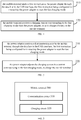
- Fig. 1 is a schematic flowchart of a fast charging method according to an embodiment of the present disclosure.
- the method as shown in Fig. 1 is executed by a mobile terminal, the mobile terminal is coupled to a power adapter via a Universal Serial Bus (USB) interface.
- the USB interface may be an ordinary USB interface, or may be a micro USB interface.
- a power line located in the USB interface is configured for charging the mobile terminal.
- the power line in the USB interface may be a VBus line and/or a ground line in the USB interface.
- a data line located in the USB interface is configured for establishing a communication between the power adapter and the mobile terminal.
- the data line may be a D+ line and/or a D- line in the USB interface.
- the so-called bidirectional communication may refer to information exchange between the power adapter and the mobile terminal.
- the mobile terminal supports an common charging mode and a fast charging mode, and a charging current under the fast charging mode is greater than a charging current under the common charging mode.
- the charging current in the common charging mode is generally less than 2.5A, and the charging current in the fast charging mode may be greater than 3A.
- the method as shown in Fig. 1 comprises:
- the mobile terminal may determine whether to be fast charged, based on current power, current voltage of a battery, or operating state of the mobile terminal, or the like.
- Step 120 the mobile terminal receives a charging current corresponding to the fast charging mode from the power adapter, so as to charge a battery in the mobile terminal.
- the power adapter instead of blindly increasing an output current to fast charge the mobile terminal, the power adapter fast charges the mobile terminal under the fast charging mode only after receiving the first instruction of the mobile terminal, thereby improving the security of the fast charging process, compared to related art.
- the method before receiving, by the mobile terminal, the charging current corresponding to the fast charging mode from the power adapter, so as to charge the battery in the mobile terminal, the method further comprises: sending, by the mobile terminal, a second instruction to the power adapter through the data line in the USB interface, the second instruction being configured for indicating a charging voltage corresponding to the fast charging mode.
- the charging voltage corresponding to the fast charging mode may be a preset charging voltage of the power adapter, or may be a charging voltage indicated through the second instruction by the mobile terminal.
- the mobile terminal may determine the charging voltage corresponding to the fast charging mode based on its operating parameters, such as battery power, voltage, and temperature and so on.
- the method before receiving, by the mobile terminal, the charging current corresponding to the fast charging mode from the power adapter, so as to charge the battery in the mobile terminal, the method further comprises: sending, by the mobile terminal, a third instruction to the power adapter through the data line in the USB interface, the third instruction being configured for indicating the charging current corresponding to the fast charging mode.
- the charging current corresponding to the fast charging mode may be a preset charging current of the power adapter, or may be a charging current indicated through the third instruction by the mobile terminal.
- the mobile terminal may determine the charging current corresponding to the fast charging mode based on its operating parameters, such as battery power, voltage, and temperature and so on.
- the method as shown in Fig. 1 may further comprise: sending, by the mobile terminal, a fourth instruction to the power adapter through the data line in the USB interface during a period of charging the mobile terminal by the power adapter under the fast charging mode, the fourth instruction being configured for indicating a current voltage of the battery in the mobile terminal such that the power adapter adjusts the charging current based on the current voltage of the battery, or determines whether a connection to the USB interface is abnormal based on the charging voltage from the power adapter and the current voltage of the battery.
- the power adapter may determine impedance of the whole circuit based on a voltage drop between its output voltage and battery voltage obtained, and determine a connection to the USB interface is abnormal when the impedance of the circuit is greater than a predetermined threshold.
- Fig. 2 is a schematic flowchart of a fast charging method according to an embodiment of the present disclosure.
- the method as shown in Fig. 2 is executed by a power adapter, the mobile terminal is coupled to a mobile terminal via a USB interface.
- a power line located in the USB interface is configured for charging the mobile terminal by the power adapter, and a data line located in the USB interface is configured for establishing a communication between the power adapter and the mobile terminal.
- the mobile terminal supports an common charging mode and a fast charging mode, and a charging current under the fast charging mode is greater than a charging current under the common charging mode.
- the method as shown in Fig. 2 comprises:
- the power adapter instead of blindly increasing an output current to fast charge the mobile terminal, the power adapter fast charges the mobile terminal under the fast charging mode only after receiving the first instruction of the mobile terminal, thereby improving the security of the fast charging process, compared to related art.
- the method as shown in Fig. 2 may further comprise: receiving, by the power adapter, a second instruction sent by the mobile terminal through the data line in the USB interface, the second instruction being configured for indicating a charging voltage corresponding to the fast charging mode.
- the method as shown in Fig. 2 may further comprise: receiving, by the power adapter, a third instruction sent by the mobile terminal through the data line in the USB interface, the third instruction being configured for indicating the charging current corresponding to the fast charging mode.
- the method as shown in Fig. 2 may further comprise: receiving, by the power adapter, a fourth instruction sent by the mobile terminal through the data line in the USB interface during a period of charging the mobile terminal by the power adapter under the fast charging mode, the fourth instruction being configured for indicating a current voltage of the battery in the mobile terminal; and adjusting, by the power adapter, the charging current based on the current voltage of the battery in the mobile terminal.
- adjusting, by the power adapter, the charging current based on the current voltage of the battery in the mobile terminal comprises: adjusting, by the power adapter, the charging current of the power adapter to the charging current corresponding to the current voltage of the battery, based on the current voltage of the battery, and the preset correspondence between the battery voltage and the charging current.
- the method as shown in Fig. 2 may further comprise: receiving, by the power adapter, a fourth instruction sent by the mobile terminal through the data line in the USB interface during a period of charging the mobile terminal by the power adapter under the fast charging mode, the fourth instruction being configured for indicating a current voltage of the battery in the mobile terminal; and determining, by the power adapter, whether a connection to the USB interface is abnormal based on the charging voltage from the power adapter and the current voltage of the battery.
- a detailed description for the fast charging method according to the embodiment of the present disclosure is provided.
- a detailed description for a mobile terminal and a power adapter according to an embodiment of the present disclosure is provided hereinafter. It should be understood that, the mobile terminal as shown in Fig. 3 may realize each of the steps as shown in Fig. 1 to Fig. 2 performed by a mobile terminal, and the power adapter as shown in Fig. 4 may realize each of the steps as shown in Fig. 1 to Fig. 2 performed by a power adapter, which is not described in detail to avoid repetition.
- Fig. 3 is a schematic block diagram of a mobile terminal according to an embodiment of the present disclosure.
- a mobile terminal 300 as shown in Fig. 3 is configured for coupling with a power adapter via a USB interface.
- a power line located in the USB interface is configured for charging the mobile terminal 300, and a data line located in the USB interface is configured for establishing a communication between the power adapter and the mobile terminal 300.
- the mobile terminal 300 supports an common charging mode and a fast charging mode, and a charging current under the fast charging mode is greater than a charging current under the common charging mode.
- the mobile terminal 300 comprises:
- the power adapter instead of blindly increasing an output current to fast charge the mobile terminal, the power adapter fast charges the mobile terminal under the fast charging mode only after receiving the first instruction of the mobile terminal, thereby improving the security of the fast charging process, compared to related art.
- the communication circuit 310 is further configured for sending a second instruction to the power adapter through the data line in the USB interface, the second instruction being configured for indicating a charging voltage corresponding to the fast charging mode.
- the communication circuit 310 is further configured for sending a third instruction to the power adapter through the data line in the USB interface, the third instruction being configured for indicating the charging current corresponding to the fast charging mode.
- the communication circuit 310 is further configured for sending a fourth instruction to the power adapter through the data line in the USB interface during a period of charging the mobile terminal 300 by the power adapter under the fast charging mode, the fourth instruction being configured for indicating a current voltage of the battery in the mobile terminal 300 such that the power adapter adjusts the charging current based on the current voltage of the battery, or determines whether a connection to the USB interface is abnormal based on the charging voltage from the power adapter and the current voltage of the battery.
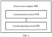
- Fig. 4 is a schematic diagram of a power adapter according to an embodiment of the present disclosure.
- the power adapter 400 as shown in Fig. 4 is configured for coupling with a mobile terminal via a USB interface.
- a power line located in the USB interface is configured for charging the mobile terminal by the power adapter 400
- a data line located in the USB interface is configured for establishing a communication between the power adapter 400 and the mobile terminal.
- the power adapter 400 supports an common charging mode and a fast charging mode, and a charging current under the fast charging mode is greater than a charging current under the common charging mode.
- the power adapter 400 comprises:
- the power adapter instead of blindly increasing an output current to fast charge the mobile terminal, the power adapter fast charges the mobile terminal under the fast charging mode only after receiving the first instruction of the mobile terminal, thereby improving the security of the fast charging process, compared to related art.
- the communication circuit 410 is further configured for receiving a second instruction sent by the mobile terminal through the data line in the USB interface, the second instruction being configured for indicating a charging voltage corresponding to the fast charging mode.
- the communication circuit 410 is further configured for receiving a third instruction sent by the mobile terminal through the data line in the USB interface, the third instruction being configured for indicating the charging current corresponding to the fast charging mode.
- the communication circuit 410 is further configured for receiving a fourth instruction sent by the mobile terminal through the data line in the USB interface during a period of charging the mobile terminal by the power adapter 400 under the fast charging mode, the fourth instruction being configured for indicating a current voltage of the battery in the mobile terminal; and the current adjusting circuit 420 is configured for adjusting the charging current based on the current voltage of the battery in the mobile terminal.
- the current adjusting circuit 420 is configured for adjusting the charging current of the power adapter 400 to the charging current corresponding to the current voltage of the battery, based on the current voltage of the battery, and the preset correspondence between the battery voltage and the charging current.
- the communication circuit 410 is further configured for receiving a fourth instruction sent by the mobile terminal through the data line in the USB interface during a period of charging the mobile terminal by the power adapter 400 under the fast charging mode, the fourth instruction being configured for indicating a current voltage of the battery in the mobile terminal; the power adapter 400 determines whether there is a poor connection between the power adapter 400 and the mobile terminal based on the charging voltage from the power adapter and the current voltage of the battery.
- the units described as separate units may be or may not be physically separated, and components shown as units may be or may not be physical units, that is to say, may be in one place, or may be distributed in several network units. A part or all of the units may be selected according to actual requirements to achieve the purpose of the solution of the present embodiments.
- various functional units in the embodiments of the present disclosure may be integrated into one processing unit, or various functional units each may exist physically separately or two or more units may be integrated into one unit.
- the functions are realized in a form of functional software units and may be sold or configured as stand-alone products, they may be stored in a computer-readable storage medium. Based on such understanding, the spirit of the technical solution of the present disclosure, or a part of the technical solution that contributes to related art or a certain part of the technical solution may be embodied in a form of software product.
- the computer software product may be stored in a storage medium, and comprise a plurality of instructions configured to instruct a computer device (personal computer, server, or network device) to execute all or a part of steps of various embodiments of the present disclosure.
- the storage medium described above comprises various medium storing program codes, such as a U-disk, a mobile hard disk, a read-only memory (ROM), a random access memory (RAM), a disc, a compact disc and so on.
Applications Claiming Priority (3)
| Application Number | Priority Date | Filing Date | Title |
|---|---|---|---|
| PCT/CN2014/090847 WO2016074160A1 (zh) | 2014-11-11 | 2014-11-11 | 通信方法、电源适配器和终端 |
| PCT/CN2015/074050 WO2016074391A1 (zh) | 2014-11-11 | 2015-03-11 | 电源适配器和终端 |
| PCT/CN2015/078905 WO2016074459A1 (zh) | 2014-11-11 | 2015-05-13 | 快速充电方法、电源适配器和移动终端 |
Publications (2)
| Publication Number | Publication Date |
|---|---|
| EP3148039A1 true EP3148039A1 (de) | 2017-03-29 |
| EP3148039A4 EP3148039A4 (de) | 2018-01-17 |
Family
ID=55953566
Family Applications (3)
| Application Number | Title | Priority Date | Filing Date |
|---|---|---|---|
| EP21190177.2A Pending EP3923443A1 (de) | 2014-11-11 | 2014-11-11 | Kommunikationsverfahren, netzadapter und endgerät |
| EP14905845.5A Active EP3220507B1 (de) | 2014-11-11 | 2014-11-11 | Kommunikationsverfahren, netzadapter und endgerät |
| EP15859023.2A Pending EP3148039A4 (de) | 2014-11-11 | 2015-05-13 | Schnellladeverfahren, stromquellenadapter und mobiles endgerät |
Family Applications Before (2)
| Application Number | Title | Priority Date | Filing Date |
|---|---|---|---|
| EP21190177.2A Pending EP3923443A1 (de) | 2014-11-11 | 2014-11-11 | Kommunikationsverfahren, netzadapter und endgerät |
| EP14905845.5A Active EP3220507B1 (de) | 2014-11-11 | 2014-11-11 | Kommunikationsverfahren, netzadapter und endgerät |
Country Status (6)
| Country | Link |
|---|---|
| US (3) | US9985449B2 (de) |
| EP (3) | EP3923443A1 (de) |
| JP (1) | JP6475826B2 (de) |
| KR (2) | KR102135606B1 (de) |
| CN (4) | CN108667094B (de) |
| WO (2) | WO2016074160A1 (de) |
Cited By (1)
| Publication number | Priority date | Publication date | Assignee | Title |
|---|---|---|---|---|
| EP3754777A4 (de) * | 2018-02-13 | 2021-04-14 | ZTE Corporation | Ladeverfahren und -vorrichtung, system, ladeschaltung, endgerät und ladesystem |
Families Citing this family (8)
| Publication number | Priority date | Publication date | Assignee | Title |
|---|---|---|---|---|
| CN108667094B (zh) * | 2014-11-11 | 2020-01-14 | Oppo广东移动通信有限公司 | 通信方法、电源适配器和终端 |
| DK3220506T3 (da) * | 2014-11-11 | 2020-05-04 | Guangdong Oppo Mobile Telecommunications Corp Ltd | Kommunikationsfremgangsmåde, strømadapter og terminal |
| DK3131171T3 (en) * | 2014-11-11 | 2019-04-15 | Guangdong Oppo Mobile Telecommunications Corp Ltd | POWER ADAPTERS, TERMINAL AND CHARGING SYSTEM |
| ES2896245T3 (es) * | 2016-01-05 | 2022-02-24 | Guangdong Oppo Mobile Telecommunications Corp Ltd | Método de carga rápida, terminal móvil y adaptador de corriente |
| CN107231013B (zh) * | 2016-05-24 | 2019-01-15 | 华为技术有限公司 | 一种充电的方法、终端、充电器和系统 |
| WO2018068243A1 (zh) * | 2016-10-12 | 2018-04-19 | 广东欧珀移动通信有限公司 | 移动终端 |
| CN109004710B (zh) * | 2018-08-01 | 2021-04-06 | 广州番禺巨大汽车音响设备有限公司 | 基于usb线的音响设备充电模式切换方法及装置 |
| CN113162199B (zh) * | 2021-05-12 | 2023-06-02 | 展讯通信(上海)有限公司 | 充电方法及装置、计算机可读存储介质 |
Family Cites Families (63)
| Publication number | Priority date | Publication date | Assignee | Title |
|---|---|---|---|---|
| JPH06284586A (ja) | 1993-03-30 | 1994-10-07 | Toyoda Mach Works Ltd | 電力供給装置 |
| JPH07308031A (ja) * | 1994-05-13 | 1995-11-21 | Toshiba Battery Co Ltd | 二次電池の充電装置 |
| JPH08126221A (ja) | 1994-10-27 | 1996-05-17 | Canon Inc | 充電装置 |
| JP2880940B2 (ja) | 1995-12-26 | 1999-04-12 | 埼玉日本電気株式会社 | 携帯電話機 |
| US5764035A (en) | 1996-09-23 | 1998-06-09 | Ericsson Inc. | System and method for automatically enabling rapid charging of a battery in a portable phone |
| KR100593127B1 (ko) | 1999-05-17 | 2006-06-26 | 마츠시타 덴끼 산교 가부시키가이샤 | 2차 전지의 보호회로 및 보호소자 |
| JP4846755B2 (ja) | 2002-04-15 | 2011-12-28 | 富士通セミコンダクター株式会社 | 携帯型電子機器 |
| US7190171B2 (en) | 2002-10-11 | 2007-03-13 | Canon Kabushiki Kaisha | Detecting method and detecting apparatus for detecting internal of rechargeable battery, rechargeable battery pack having said detecting apparatus therein, apparatus having said detecting apparatus therein, program in which said detecting method is incorporated, and medium in which said program is stored |
| GB0313520D0 (en) * | 2003-06-12 | 2003-07-16 | Koninkl Philips Electronics Nv | Wireless battery charger detection and notification |
| KR101011922B1 (ko) | 2003-07-31 | 2011-02-01 | 엘지전자 주식회사 | 배터리 충전 장치 및 방법 |
| JP2007141164A (ja) | 2005-11-22 | 2007-06-07 | Sharp Corp | 給電システム、電子装置及び電力供給具 |
| JP2007189789A (ja) | 2006-01-11 | 2007-07-26 | Sanyo Electric Co Ltd | パック電池、電子機器 |
| US7531986B2 (en) | 2006-02-23 | 2009-05-12 | Eveready Battery Company, Inc. | Power supply for battery powered devices |
| JP5020530B2 (ja) * | 2006-04-14 | 2012-09-05 | パナソニック株式会社 | 充電方法ならびに電池パックおよびその充電器 |
| US7701168B2 (en) | 2007-03-23 | 2010-04-20 | Sony Ericsson Mobile Communications Ab | Universal serial bus charger device |
| KR101494900B1 (ko) | 2007-07-25 | 2015-02-24 | 삼성전자주식회사 | 충전 장치 식별을 통한 충전 기능을 갖는 휴대 단말기 및방법 |
| CN101399386B (zh) | 2007-09-25 | 2012-04-18 | 南京德朔实业有限公司 | 一种锂电池包及其充电方法 |
| US20120153891A1 (en) * | 2007-11-07 | 2012-06-21 | Yung-Tai Yang | Portable electronic apparatus and circuit and method for charging rechargeable battery thereof |
| CN101651403A (zh) * | 2008-08-13 | 2010-02-17 | 鸿富锦精密工业(深圳)有限公司 | 供电设备,用电设备,供用电系统以及供电方法,用电方法 |
| CN101771178A (zh) | 2008-12-29 | 2010-07-07 | 深圳易拓科技有限公司 | 一种采用usb接口的充电方法 |
| WO2010084599A1 (ja) | 2009-01-23 | 2010-07-29 | トヨタ自動車株式会社 | 充電制御装置 |
| US8386814B2 (en) * | 2009-07-20 | 2013-02-26 | Texas Instruments Incorporated | Continuous monitoring of a USB client for battery charging specification charging capacity |
| DE102009036816A1 (de) | 2009-08-10 | 2011-02-17 | Rwe Ag | Steuerung von Ladestationen |
| US8350522B2 (en) | 2010-03-10 | 2013-01-08 | Apple Inc. | External power source voltage drop compensation for portable devices |
| US8717044B2 (en) | 2010-04-23 | 2014-05-06 | Apple Inc. | Charging systems with direct charging port support and extended capabilities |
| CN102270860B (zh) * | 2010-06-07 | 2015-08-19 | 技嘉科技股份有限公司 | 智能型手机的快充装置 |
| JP2012143092A (ja) | 2011-01-04 | 2012-07-26 | Kimitake Utsunomiya | 充電acアダプタ |
| JP5668542B2 (ja) | 2011-03-11 | 2015-02-12 | 日産自動車株式会社 | 車両の充電制御装置 |
| JP2012223077A (ja) | 2011-04-14 | 2012-11-12 | Kyocera Corp | 充電システム |
| US8836287B2 (en) * | 2011-05-03 | 2014-09-16 | Apple Inc. | Time-domain multiplexing of power and data |
| CN102820682B (zh) | 2011-06-09 | 2016-01-20 | 中兴通讯股份有限公司 | 一种通过usb接口通信并为外部设备充电的装置及方法 |
| CN102270680B (zh) | 2011-08-25 | 2013-08-28 | 广东保威新能源有限公司 | 立柱安装偏心可调螺旋地桩 |
| CN102427260A (zh) | 2011-12-02 | 2012-04-25 | 苏州冠硕新能源有限公司 | 充电管理系统及采用该充电管理系统的充电器 |
| KR20130083116A (ko) | 2012-01-12 | 2013-07-22 | 삼성전자주식회사 | 단말기의 배터리 충전 제어 방법 및 시스템 |
| JP5773920B2 (ja) | 2012-03-19 | 2015-09-02 | ルネサスエレクトロニクス株式会社 | 充電装置 |
| CN102868820A (zh) * | 2012-09-19 | 2013-01-09 | 中兴通讯股份有限公司 | 移动终端、数据通信主设备和移动终端充电系统及方法 |
| WO2014077978A1 (en) * | 2012-11-14 | 2014-05-22 | Apple Inc. | High voltage charging for a portable device |
| CN102957193B (zh) * | 2012-11-19 | 2015-12-23 | 中兴通讯股份有限公司 | 一种充电管理方法、装置和系统 |
| CN103066340B (zh) | 2012-12-17 | 2015-08-12 | 中兴通讯股份有限公司 | 充电方法、移动终端及适配器 |
| JP5495407B1 (ja) * | 2012-12-21 | 2014-05-21 | パナソニック株式会社 | 電子機器、充電器及び電子機器システム |
| KR20140120699A (ko) * | 2013-04-04 | 2014-10-14 | 삼성전자주식회사 | 충전을 위한 전자 장치 제어 방법 및 이를 지원하는 전자 장치와 충전 장치 |
| US9356460B2 (en) * | 2013-08-05 | 2016-05-31 | Texas Instruments Incorporated | Method and apparatus of fast battery charging with universal high power input source |
| JP5949701B2 (ja) | 2013-08-20 | 2016-07-13 | 富士通株式会社 | 充電システム及び処理装置 |
| CN203617746U (zh) | 2013-11-26 | 2014-05-28 | 比亚迪股份有限公司 | 一种电动车、充电装置及其充电控制引导电路 |
| CN103730933A (zh) | 2013-12-23 | 2014-04-16 | 联想(北京)有限公司 | 一种充电方法及电子设备 |
| CN203722283U (zh) | 2013-12-27 | 2014-07-16 | 中兴通讯股份有限公司 | 一种充电电缆及充电系统 |
| CN203747454U (zh) * | 2014-01-28 | 2014-07-30 | 广东欧珀移动通信有限公司 | 电子设备充电控制装置 |
| CN103746434B (zh) * | 2014-01-28 | 2016-04-06 | 广东欧珀移动通信有限公司 | 充电方法和系统 |
| CN106165236B (zh) | 2014-01-28 | 2018-06-29 | 广东欧珀移动通信有限公司 | 终端、电源适配器和充电异常的处理方法 |
| CN103762702B (zh) * | 2014-01-28 | 2015-12-16 | 广东欧珀移动通信有限公司 | 电子设备充电装置及其电源适配器 |
| CN103779907B (zh) * | 2014-01-28 | 2016-11-23 | 广东欧珀移动通信有限公司 | 终端及其电池充电控制装置与方法 |
| CN103762690B (zh) * | 2014-01-28 | 2016-08-24 | 广东欧珀移动通信有限公司 | 充电系统 |
| CN104124483B (zh) * | 2014-05-23 | 2016-05-04 | 东莞市钜大电子有限公司 | 一种移动电源快速充电方法及系统 |
| CN104065147B (zh) * | 2014-06-27 | 2017-06-06 | 宇龙计算机通信科技(深圳)有限公司 | 一种充电适配器、终端、充电控制方法 |
| CN104065126B (zh) * | 2014-06-27 | 2017-01-25 | 宇龙计算机通信科技(深圳)有限公司 | 一种充电器、终端和充电方法 |
| CN104092274A (zh) * | 2014-07-29 | 2014-10-08 | 深圳市至高通信技术发展有限公司 | 一种智能可变换输出电压的充电器 |
| CN104135057B (zh) | 2014-08-13 | 2016-05-18 | 宇龙计算机通信科技(深圳)有限公司 | 终端、充电器和充电方法 |
| CN104393628B (zh) | 2014-08-29 | 2017-02-01 | 展讯通信(上海)有限公司 | Usb充电器、移动终端和充电控制方法 |
| CN104393627B (zh) * | 2014-08-29 | 2017-06-30 | 展讯通信(上海)有限公司 | Usb充电器、移动终端和充电控制方法 |
| CN104269893B (zh) | 2014-09-11 | 2017-08-04 | 深圳天珑无线科技有限公司 | 充电控制方法以及充电系统 |
| DK3220506T3 (da) * | 2014-11-11 | 2020-05-04 | Guangdong Oppo Mobile Telecommunications Corp Ltd | Kommunikationsfremgangsmåde, strømadapter og terminal |
| DK3131171T3 (en) * | 2014-11-11 | 2019-04-15 | Guangdong Oppo Mobile Telecommunications Corp Ltd | POWER ADAPTERS, TERMINAL AND CHARGING SYSTEM |
| CN108667094B (zh) * | 2014-11-11 | 2020-01-14 | Oppo广东移动通信有限公司 | 通信方法、电源适配器和终端 |
-
2014
- 2014-11-11 CN CN201810461219.XA patent/CN108667094B/zh active Active
- 2014-11-11 EP EP21190177.2A patent/EP3923443A1/de active Pending
- 2014-11-11 WO PCT/CN2014/090847 patent/WO2016074160A1/zh active Application Filing
- 2014-11-11 EP EP14905845.5A patent/EP3220507B1/de active Active
- 2014-11-11 CN CN201480073122.1A patent/CN105900312B/zh active Active
- 2014-11-11 US US15/122,459 patent/US9985449B2/en active Active
-
2015
- 2015-05-13 KR KR1020197027788A patent/KR102135606B1/ko active IP Right Grant
- 2015-05-13 CN CN201810716984.1A patent/CN108988415A/zh active Pending
- 2015-05-13 EP EP15859023.2A patent/EP3148039A4/de active Pending
- 2015-05-13 CN CN201580004522.1A patent/CN106030962B/zh active Active
- 2015-05-13 JP JP2017518081A patent/JP6475826B2/ja active Active
- 2015-05-13 KR KR1020177003394A patent/KR20170020536A/ko active Application Filing
- 2015-05-13 WO PCT/CN2015/078905 patent/WO2016074459A1/zh active Application Filing
-
2017
- 2017-01-13 US US15/405,771 patent/US10454288B2/en active Active
-
2018
- 2018-11-21 US US16/198,662 patent/US10326291B2/en active Active
Cited By (1)
| Publication number | Priority date | Publication date | Assignee | Title |
|---|---|---|---|---|
| EP3754777A4 (de) * | 2018-02-13 | 2021-04-14 | ZTE Corporation | Ladeverfahren und -vorrichtung, system, ladeschaltung, endgerät und ladesystem |
Also Published As
| Publication number | Publication date |
|---|---|
| US20170149252A1 (en) | 2017-05-25 |
| US20170237273A1 (en) | 2017-08-17 |
| CN108667094B (zh) | 2020-01-14 |
| KR20190110160A (ko) | 2019-09-27 |
| US20190157886A1 (en) | 2019-05-23 |
| KR102135606B1 (ko) | 2020-07-21 |
| US10454288B2 (en) | 2019-10-22 |
| WO2016074160A1 (zh) | 2016-05-19 |
| EP3220507A1 (de) | 2017-09-20 |
| EP3923443A1 (de) | 2021-12-15 |
| CN106030962A (zh) | 2016-10-12 |
| CN108667094A (zh) | 2018-10-16 |
| WO2016074459A1 (zh) | 2016-05-19 |
| CN106030962B (zh) | 2018-09-04 |
| JP6475826B2 (ja) | 2019-02-27 |
| US10326291B2 (en) | 2019-06-18 |
| EP3220507A4 (de) | 2018-04-04 |
| KR20170020536A (ko) | 2017-02-22 |
| JP2017531984A (ja) | 2017-10-26 |
| EP3148039A4 (de) | 2018-01-17 |
| CN105900312B (zh) | 2018-05-29 |
| EP3220507B1 (de) | 2021-09-01 |
| US9985449B2 (en) | 2018-05-29 |
| CN108988415A (zh) | 2018-12-11 |
| CN105900312A (zh) | 2016-08-24 |
Similar Documents
| Publication | Publication Date | Title |
|---|---|---|
| US10326291B2 (en) | Quick charging method, power adapter and mobile terminal | |
| US10910853B2 (en) | Quick charging method, power adapter and mobile terminal | |
| EP3131171B1 (de) | Stromadapter, anschlussklemme und ladesystem | |
| CN109149694B (zh) | 充电方法、充电装置、电源提供设备及待充电终端 | |
| JP6275856B2 (ja) | 端末、電源アダプター及び充電異常の処理方法 | |
| CN108988417B (zh) | 电源适配器和终端 | |
| EP3101770B1 (de) | Netzadapter und anschluss | |
| CN110582917A (zh) | 一种充电方法、终端及计算机存储介质 |
Legal Events
| Date | Code | Title | Description |
|---|---|---|---|
| STAA | Information on the status of an ep patent application or granted ep patent |
Free format text: STATUS: THE INTERNATIONAL PUBLICATION HAS BEEN MADE |
|
| PUAI | Public reference made under article 153(3) epc to a published international application that has entered the european phase |
Free format text: ORIGINAL CODE: 0009012 |
|
| STAA | Information on the status of an ep patent application or granted ep patent |
Free format text: STATUS: REQUEST FOR EXAMINATION WAS MADE |
|
| 17P | Request for examination filed |
Effective date: 20161222 |
|
| AK | Designated contracting states |
Kind code of ref document: A1 Designated state(s): AL AT BE BG CH CY CZ DE DK EE ES FI FR GB GR HR HU IE IS IT LI LT LU LV MC MK MT NL NO PL PT RO RS SE SI SK SM TR |
|
| AX | Request for extension of the european patent |
Extension state: BA ME |
|
| A4 | Supplementary search report drawn up and despatched |
Effective date: 20171215 |
|
| RIC1 | Information provided on ipc code assigned before grant |
Ipc: H02J 7/04 20060101ALI20171211BHEP Ipc: H02J 7/00 20060101AFI20171211BHEP Ipc: H01M 10/44 20060101ALI20171211BHEP |
|
| DAV | Request for validation of the european patent (deleted) | ||
| DAX | Request for extension of the european patent (deleted) | ||
| RAP1 | Party data changed (applicant data changed or rights of an application transferred) |
Owner name: GUANGDONG OPPO MOBILE TELECOMMUNICATIONS CORP., LT |
|
| STAA | Information on the status of an ep patent application or granted ep patent |
Free format text: STATUS: EXAMINATION IS IN PROGRESS |
|
| 17Q | First examination report despatched |
Effective date: 20200218 |
|
| STAA | Information on the status of an ep patent application or granted ep patent |
Free format text: STATUS: EXAMINATION IS IN PROGRESS |
|
| STAA | Information on the status of an ep patent application or granted ep patent |
Free format text: STATUS: EXAMINATION IS IN PROGRESS |