EP3148039A1 - Fast charging method, power source adapter and mobile terminal - Google Patents
Fast charging method, power source adapter and mobile terminal Download PDFInfo
- Publication number
- EP3148039A1 EP3148039A1 EP15859023.2A EP15859023A EP3148039A1 EP 3148039 A1 EP3148039 A1 EP 3148039A1 EP 15859023 A EP15859023 A EP 15859023A EP 3148039 A1 EP3148039 A1 EP 3148039A1
- Authority
- EP
- European Patent Office
- Prior art keywords
- mobile terminal
- power adapter
- charging
- instruction
- charging mode
- Prior art date
- Legal status (The legal status is an assumption and is not a legal conclusion. Google has not performed a legal analysis and makes no representation as to the accuracy of the status listed.)
- Pending
Links
Images
Classifications
-
- H—ELECTRICITY
- H02—GENERATION; CONVERSION OR DISTRIBUTION OF ELECTRIC POWER
- H02J—CIRCUIT ARRANGEMENTS OR SYSTEMS FOR SUPPLYING OR DISTRIBUTING ELECTRIC POWER; SYSTEMS FOR STORING ELECTRIC ENERGY
- H02J7/00—Circuit arrangements for charging or depolarising batteries or for supplying loads from batteries
- H02J7/007—Regulation of charging or discharging current or voltage
-
- H—ELECTRICITY
- H02—GENERATION; CONVERSION OR DISTRIBUTION OF ELECTRIC POWER
- H02J—CIRCUIT ARRANGEMENTS OR SYSTEMS FOR SUPPLYING OR DISTRIBUTING ELECTRIC POWER; SYSTEMS FOR STORING ELECTRIC ENERGY
- H02J7/00—Circuit arrangements for charging or depolarising batteries or for supplying loads from batteries
-
- G—PHYSICS
- G01—MEASURING; TESTING
- G01R—MEASURING ELECTRIC VARIABLES; MEASURING MAGNETIC VARIABLES
- G01R31/00—Arrangements for testing electric properties; Arrangements for locating electric faults; Arrangements for electrical testing characterised by what is being tested not provided for elsewhere
- G01R31/50—Testing of electric apparatus, lines, cables or components for short-circuits, continuity, leakage current or incorrect line connections
- G01R31/66—Testing of connections, e.g. of plugs or non-disconnectable joints
- G01R31/67—Testing the correctness of wire connections in electric apparatus or circuits
-
- G—PHYSICS
- G06—COMPUTING; CALCULATING OR COUNTING
- G06F—ELECTRIC DIGITAL DATA PROCESSING
- G06F1/00—Details not covered by groups G06F3/00 - G06F13/00 and G06F21/00
- G06F1/16—Constructional details or arrangements
- G06F1/20—Cooling means
- G06F1/206—Cooling means comprising thermal management
-
- G—PHYSICS
- G06—COMPUTING; CALCULATING OR COUNTING
- G06F—ELECTRIC DIGITAL DATA PROCESSING
- G06F1/00—Details not covered by groups G06F3/00 - G06F13/00 and G06F21/00
- G06F1/26—Power supply means, e.g. regulation thereof
-
- H—ELECTRICITY
- H02—GENERATION; CONVERSION OR DISTRIBUTION OF ELECTRIC POWER
- H02J—CIRCUIT ARRANGEMENTS OR SYSTEMS FOR SUPPLYING OR DISTRIBUTING ELECTRIC POWER; SYSTEMS FOR STORING ELECTRIC ENERGY
- H02J7/00—Circuit arrangements for charging or depolarising batteries or for supplying loads from batteries
- H02J7/0029—Circuit arrangements for charging or depolarising batteries or for supplying loads from batteries with safety or protection devices or circuits
- H02J7/0036—Circuit arrangements for charging or depolarising batteries or for supplying loads from batteries with safety or protection devices or circuits using connection detecting circuits
-
- H—ELECTRICITY
- H02—GENERATION; CONVERSION OR DISTRIBUTION OF ELECTRIC POWER
- H02J—CIRCUIT ARRANGEMENTS OR SYSTEMS FOR SUPPLYING OR DISTRIBUTING ELECTRIC POWER; SYSTEMS FOR STORING ELECTRIC ENERGY
- H02J7/00—Circuit arrangements for charging or depolarising batteries or for supplying loads from batteries
- H02J7/0042—Circuit arrangements for charging or depolarising batteries or for supplying loads from batteries characterised by the mechanical construction
- H02J7/0044—Circuit arrangements for charging or depolarising batteries or for supplying loads from batteries characterised by the mechanical construction specially adapted for holding portable devices containing batteries
-
- H—ELECTRICITY
- H02—GENERATION; CONVERSION OR DISTRIBUTION OF ELECTRIC POWER
- H02J—CIRCUIT ARRANGEMENTS OR SYSTEMS FOR SUPPLYING OR DISTRIBUTING ELECTRIC POWER; SYSTEMS FOR STORING ELECTRIC ENERGY
- H02J7/00—Circuit arrangements for charging or depolarising batteries or for supplying loads from batteries
- H02J7/0042—Circuit arrangements for charging or depolarising batteries or for supplying loads from batteries characterised by the mechanical construction
- H02J7/0045—Circuit arrangements for charging or depolarising batteries or for supplying loads from batteries characterised by the mechanical construction concerning the insertion or the connection of the batteries
-
- H—ELECTRICITY
- H02—GENERATION; CONVERSION OR DISTRIBUTION OF ELECTRIC POWER
- H02J—CIRCUIT ARRANGEMENTS OR SYSTEMS FOR SUPPLYING OR DISTRIBUTING ELECTRIC POWER; SYSTEMS FOR STORING ELECTRIC ENERGY
- H02J7/00—Circuit arrangements for charging or depolarising batteries or for supplying loads from batteries
- H02J7/02—Circuit arrangements for charging or depolarising batteries or for supplying loads from batteries for charging batteries from ac mains by converters
- H02J7/04—Regulation of charging current or voltage
-
- H—ELECTRICITY
- H02—GENERATION; CONVERSION OR DISTRIBUTION OF ELECTRIC POWER
- H02J—CIRCUIT ARRANGEMENTS OR SYSTEMS FOR SUPPLYING OR DISTRIBUTING ELECTRIC POWER; SYSTEMS FOR STORING ELECTRIC ENERGY
- H02J7/00—Circuit arrangements for charging or depolarising batteries or for supplying loads from batteries
- H02J7/00032—Circuit arrangements for charging or depolarising batteries or for supplying loads from batteries characterised by data exchange
- H02J7/00034—Charger exchanging data with an electronic device, i.e. telephone, whose internal battery is under charge
-
- H—ELECTRICITY
- H02—GENERATION; CONVERSION OR DISTRIBUTION OF ELECTRIC POWER
- H02J—CIRCUIT ARRANGEMENTS OR SYSTEMS FOR SUPPLYING OR DISTRIBUTING ELECTRIC POWER; SYSTEMS FOR STORING ELECTRIC ENERGY
- H02J7/00—Circuit arrangements for charging or depolarising batteries or for supplying loads from batteries
- H02J7/00032—Circuit arrangements for charging or depolarising batteries or for supplying loads from batteries characterised by data exchange
- H02J7/00045—Authentication, i.e. circuits for checking compatibility between one component, e.g. a battery or a battery charger, and another component, e.g. a power source
Definitions
- the present disclosure relates to the field of battery charging, and more particularly, to a fast charging method, a power adapter and a mobile terminal using the same.
- Embodiments of the present disclosure provide a fast charging method, a power adapter and a mobile terminal, in order to improve the security of fast charging process.
- a first aspect provides a fast charging method, wherein the method is executed by a mobile terminal, the mobile terminal is coupled to a power adapter via a USB (Universal Serial Bus) interface; a power line located in the USB interface is configured for charging the mobile terminal, a data line located in the USB interface is configured for establishing a communication between the power adapter and the mobile terminal; the mobile terminal supports an common charging mode and a fast charging mode, and a charging current under the fast charging mode is greater than a charging current under the common charging mode; the method comprises: sending, by the mobile terminal, a first instruction to the power adapter through the data line in the USB interface, the first instruction being configured for instructing the power adapter to start the fast charging mode; and receiving, by the mobile terminal, a charging current corresponding to the fast charging mode from the power adapter, so as to charge a battery in the mobile terminal.
- a USB Universal Serial Bus
- the method before receiving, by the mobile terminal, the charging current corresponding to the fast charging mode from the power adapter, so as to charge the battery in the mobile terminal, the method further comprises: sending, by the mobile terminal, a second instruction to the power adapter through the data line in the USB interface, the second instruction being configured for indicating a charging voltage corresponding to the fast charging mode.
- the method before receiving, by the mobile terminal, the charging current corresponding to the fast charging mode from the power adapter, so as to charge the battery in the mobile terminal, the method further comprises: sending, by the mobile terminal, a third instruction to the power adapter through the data line in the USB interface, the third instruction being configured for indicating the charging current corresponding to the fast charging mode.
- the method further comprises: sending, by the mobile terminal, a fourth instruction to the power adapter through the data line in the USB interface during a period of charging the mobile terminal by the power adapter under the fast charging mode, the fourth instruction being configured for indicating a current voltage of the battery in the mobile terminal such that the power adapter adjusts the charging current based on the current voltage of the battery, or determines whether a connection to the USB interface is abnormal based on the charging voltage from the power adapter and the current voltage of the battery.
- a second aspect provides a fast charging method, wherein the method is executed by a power adapter, the power adapter is coupled to a mobile terminal via a USB (Universal Serial Bus) interface; a power line located in the USB interface is configured for charging the mobile terminal by the power adapter, a data line located in the USB interface is configured for establishing a communication between the power adapter and the mobile terminal; the mobile terminal supports an common charging mode and a fast charging mode, and a charging current under the fast charging mode is greater than a charging current under the common charging mode; the method comprises: receiving, by the power adapter, a first instruction sent by the mobile terminal through the data line in the USB interface, the first instruction being configured for instructing the power adapter to start the fast charging mode; and adjusting, by the power adapter, the charging current to a current corresponding to the fast charging mode, to charge the mobile terminal.
- a USB Universal Serial Bus
- the method before adjusting, by the power adapter, the charging current to the current corresponding to the fast charging mode, to charge the mobile terminal, further comprises: receiving, by the power adapter, a second instruction sent by the mobile terminal through the data line in the USB interface, the second instruction being configured for indicating a charging voltage corresponding to the fast charging mode.
- the method before adjusting, by the power adapter, the charging current to the current corresponding to the fast charging mode, to charge the mobile terminal, further comprises: receiving, by the power adapter, a third instruction sent by the mobile terminal through the data line in the USB interface, the third instruction being configured for indicating the charging current corresponding to the fast charging mode.
- the method further comprises: receiving, by the power adapter, a fourth instruction sent by the mobile terminal through the data line in the USB interface during a period of charging the mobile terminal by the power adapter under the fast charging mode, the fourth instruction being configured for indicating a current voltage of the battery in the mobile terminal; and adjusting, by the power adapter, the charging current based on the current voltage of the battery in the mobile terminal.
- adjusting, by the power adapter, the charging current based on the current voltage of the battery in the mobile terminal comprises: adjusting, by the power adapter, the charging current of the power adapter to the charging current corresponding to the current voltage of the battery, based on the current voltage of the battery, and the preset correspondence between the battery voltage and the charging current.
- the method further comprises: receiving, by the power adapter, a fourth instruction sent by the mobile terminal through the data line in the USB interface during a period of charging the mobile terminal by the power adapter under the fast charging mode, the fourth instruction being configured for indicating a current voltage of the battery in the mobile terminal; and determining, by the power adapter, whether a connection to the USB interface is abnormal based on the charging voltage from the power adapter and the current voltage of the battery.
- the third aspect provides a mobile terminal, wherein the mobile terminal is configured for coupling with a power adapter via a USB (Universal Serial Bus) interface; a power line located in the USB interface is configured for charging the mobile terminal, a data line located in the USB interface is configured for establishing a communication between the power adapter and the mobile terminal; the mobile terminal supports an common charging mode and a fast charging mode, and a charging current under the fast charging mode is greater than a charging current under the common charging mode; the mobile terminal comprises: a communication unit configured for sending a first instruction to the power adapter through the data line in the USB interface, the first instruction being configured for instructing the power adapter to start the fast charging mode; and a charging unit configured for receiving a charging current corresponding to the fast charging mode from the power adapter, so as to charge a battery in the mobile terminal.
- a USB Universal Serial Bus
- the communication unit is further configured for sending a second instruction to the power adapter through the data line in the USB interface, the second instruction being configured for indicating a charging voltage corresponding to the fast charging mode.
- the communication unit is further configured for sending a third instruction to the power adapter through the data line in the USB interface, the third instruction being configured for indicating the charging current corresponding to the fast charging mode.
- the communication unit is further configured for sending a fourth instruction to the power adapter through the data line in the USB interface during a period of charging the mobile terminal by the power adapter under the fast charging mode, the fourth instruction being configured for indicating a current voltage of the battery in the mobile terminal such that the power adapter adjusts the charging current based on the current voltage of the battery, or determines whether a connection to the USB interface is abnormal based on the charging voltage from the power adapter and the current voltage of the battery.
- the fourth aspect provides a power adapter, wherein the power adapter is configured for coupling with a mobile terminal via a USB (Universal Serial Bus) interface; a power line located in the USB interface is configured for charging the mobile terminal by the power adapter, a data line located in the USB interface is configured for establishing a communication between the power adapter and the mobile terminal; the mobile terminal supports an common charging mode and a fast charging mode, and a charging current under the fast charging mode is greater than a charging current under the common charging mode; the power adapter comprises: a communication unit configured for receiving a first instruction sent by the mobile terminal through the data line in the USB interface, the first instruction being configured for instructing the power adapter to start the fast charging mode; and a current adjusting unit configured for adjusting a charging current to a current corresponding to the fast charging mode, to charge the mobile terminal.
- a USB Universal Serial Bus
- the communication unit is further configured for receiving a second instruction sent by the mobile terminal through the data line in the USB interface, the second instruction being configured for indicating a charging voltage corresponding to the fast charging mode.
- the communication unit is further configured for receiving a third instruction sent by the mobile terminal through the data line in the USB interface, the third instruction being configured for indicating the charging current corresponding to the fast charging mode.
- the communication unit is further configured for receiving a fourth instruction sent by the mobile terminal through the data line in the USB interface during a period of charging the mobile terminal by the power adapter under the fast charging mode, the fourth instruction being configured for indicating a current voltage of the battery in the mobile terminal; and the current adjusting unit is configured for adjusting the charging current based on the current voltage of the battery in the mobile terminal.
- the current adjusting unit is configured for adjusting the charging current of the power adapter to the charging current corresponding to the current voltage of the battery, based on the current voltage of the battery, and the preset correspondence between the battery voltage and the charging current.
- the communication unit is further configured for receiving a fourth instruction sent by the mobile terminal through the data line in the USB interface during a period of charging the mobile terminal by the power adapter under the fast charging mode, the fourth instruction being configured for indicating a current voltage of the battery in the mobile terminal; the power adapter determines whether a connection to the USB interface is abnormal based on the charging voltage from the power adapter and the current voltage of the battery.
- the power adapter instead of blindly increasing an output current to fast charge the mobile terminal, the power adapter fast charges the mobile terminal under the fast charging mode only after receiving the first instruction of the mobile terminal, thereby improving the security of the fast charging process, compared to related art.
- Fig. 1 is a schematic flowchart of a fast charging method according to an embodiment of the present disclosure.
- the method as shown in Fig. 1 is executed by a mobile terminal, the mobile terminal is coupled to a power adapter via a Universal Serial Bus (USB) interface.
- the USB interface may be an ordinary USB interface, or may be a micro USB interface.
- a power line located in the USB interface is configured for charging the mobile terminal.
- the power line in the USB interface may be a VBus line and/or a ground line in the USB interface.
- a data line located in the USB interface is configured for establishing a communication between the power adapter and the mobile terminal.
- the data line may be a D+ line and/or a D- line in the USB interface.
- the so-called bidirectional communication may refer to information exchange between the power adapter and the mobile terminal.
- the mobile terminal supports an common charging mode and a fast charging mode, and a charging current under the fast charging mode is greater than a charging current under the common charging mode.
- the charging current in the common charging mode is generally less than 2.5A, and the charging current in the fast charging mode may be greater than 3A.
- the method as shown in Fig. 1 comprises:
- the mobile terminal may determine whether to be fast charged, based on current power, current voltage of a battery, or operating state of the mobile terminal, or the like.
- Step 120 the mobile terminal receives a charging current corresponding to the fast charging mode from the power adapter, so as to charge a battery in the mobile terminal.
- the power adapter instead of blindly increasing an output current to fast charge the mobile terminal, the power adapter fast charges the mobile terminal under the fast charging mode only after receiving the first instruction of the mobile terminal, thereby improving the security of the fast charging process, compared to related art.
- the method before receiving, by the mobile terminal, the charging current corresponding to the fast charging mode from the power adapter, so as to charge the battery in the mobile terminal, the method further comprises: sending, by the mobile terminal, a second instruction to the power adapter through the data line in the USB interface, the second instruction being configured for indicating a charging voltage corresponding to the fast charging mode.
- the charging voltage corresponding to the fast charging mode may be a preset charging voltage of the power adapter, or may be a charging voltage indicated through the second instruction by the mobile terminal.
- the mobile terminal may determine the charging voltage corresponding to the fast charging mode based on its operating parameters, such as battery power, voltage, and temperature and so on.
- the method before receiving, by the mobile terminal, the charging current corresponding to the fast charging mode from the power adapter, so as to charge the battery in the mobile terminal, the method further comprises: sending, by the mobile terminal, a third instruction to the power adapter through the data line in the USB interface, the third instruction being configured for indicating the charging current corresponding to the fast charging mode.
- the charging current corresponding to the fast charging mode may be a preset charging current of the power adapter, or may be a charging current indicated through the third instruction by the mobile terminal.
- the mobile terminal may determine the charging current corresponding to the fast charging mode based on its operating parameters, such as battery power, voltage, and temperature and so on.
- the method as shown in Fig. 1 may further comprise: sending, by the mobile terminal, a fourth instruction to the power adapter through the data line in the USB interface during a period of charging the mobile terminal by the power adapter under the fast charging mode, the fourth instruction being configured for indicating a current voltage of the battery in the mobile terminal such that the power adapter adjusts the charging current based on the current voltage of the battery, or determines whether a connection to the USB interface is abnormal based on the charging voltage from the power adapter and the current voltage of the battery.
- the power adapter may determine impedance of the whole circuit based on a voltage drop between its output voltage and battery voltage obtained, and determine a connection to the USB interface is abnormal when the impedance of the circuit is greater than a predetermined threshold.
- Fig. 2 is a schematic flowchart of a fast charging method according to an embodiment of the present disclosure.
- the method as shown in Fig. 2 is executed by a power adapter, the mobile terminal is coupled to a mobile terminal via a USB interface.
- a power line located in the USB interface is configured for charging the mobile terminal by the power adapter, and a data line located in the USB interface is configured for establishing a communication between the power adapter and the mobile terminal.
- the mobile terminal supports an common charging mode and a fast charging mode, and a charging current under the fast charging mode is greater than a charging current under the common charging mode.
- the method as shown in Fig. 2 comprises:
- the power adapter instead of blindly increasing an output current to fast charge the mobile terminal, the power adapter fast charges the mobile terminal under the fast charging mode only after receiving the first instruction of the mobile terminal, thereby improving the security of the fast charging process, compared to related art.
- the method as shown in Fig. 2 may further comprise: receiving, by the power adapter, a second instruction sent by the mobile terminal through the data line in the USB interface, the second instruction being configured for indicating a charging voltage corresponding to the fast charging mode.
- the method as shown in Fig. 2 may further comprise: receiving, by the power adapter, a third instruction sent by the mobile terminal through the data line in the USB interface, the third instruction being configured for indicating the charging current corresponding to the fast charging mode.
- the method as shown in Fig. 2 may further comprise: receiving, by the power adapter, a fourth instruction sent by the mobile terminal through the data line in the USB interface during a period of charging the mobile terminal by the power adapter under the fast charging mode, the fourth instruction being configured for indicating a current voltage of the battery in the mobile terminal; and adjusting, by the power adapter, the charging current based on the current voltage of the battery in the mobile terminal.
- adjusting, by the power adapter, the charging current based on the current voltage of the battery in the mobile terminal comprises: adjusting, by the power adapter, the charging current of the power adapter to the charging current corresponding to the current voltage of the battery, based on the current voltage of the battery, and the preset correspondence between the battery voltage and the charging current.
- the method as shown in Fig. 2 may further comprise: receiving, by the power adapter, a fourth instruction sent by the mobile terminal through the data line in the USB interface during a period of charging the mobile terminal by the power adapter under the fast charging mode, the fourth instruction being configured for indicating a current voltage of the battery in the mobile terminal; and determining, by the power adapter, whether a connection to the USB interface is abnormal based on the charging voltage from the power adapter and the current voltage of the battery.
- a detailed description for the fast charging method according to the embodiment of the present disclosure is provided.
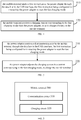
- a detailed description for a mobile terminal and a power adapter according to an embodiment of the present disclosure is provided hereinafter. It should be understood that, the mobile terminal as shown in Fig. 3 may realize each of the steps as shown in Fig. 1 to Fig. 2 performed by a mobile terminal, and the power adapter as shown in Fig. 4 may realize each of the steps as shown in Fig. 1 to Fig. 2 performed by a power adapter, which is not described in detail to avoid repetition.
- Fig. 3 is a schematic block diagram of a mobile terminal according to an embodiment of the present disclosure.
- a mobile terminal 300 as shown in Fig. 3 is configured for coupling with a power adapter via a USB interface.
- a power line located in the USB interface is configured for charging the mobile terminal 300, and a data line located in the USB interface is configured for establishing a communication between the power adapter and the mobile terminal 300.
- the mobile terminal 300 supports an common charging mode and a fast charging mode, and a charging current under the fast charging mode is greater than a charging current under the common charging mode.
- the mobile terminal 300 comprises:
- the power adapter instead of blindly increasing an output current to fast charge the mobile terminal, the power adapter fast charges the mobile terminal under the fast charging mode only after receiving the first instruction of the mobile terminal, thereby improving the security of the fast charging process, compared to related art.
- the communication circuit 310 is further configured for sending a second instruction to the power adapter through the data line in the USB interface, the second instruction being configured for indicating a charging voltage corresponding to the fast charging mode.
- the communication circuit 310 is further configured for sending a third instruction to the power adapter through the data line in the USB interface, the third instruction being configured for indicating the charging current corresponding to the fast charging mode.
- the communication circuit 310 is further configured for sending a fourth instruction to the power adapter through the data line in the USB interface during a period of charging the mobile terminal 300 by the power adapter under the fast charging mode, the fourth instruction being configured for indicating a current voltage of the battery in the mobile terminal 300 such that the power adapter adjusts the charging current based on the current voltage of the battery, or determines whether a connection to the USB interface is abnormal based on the charging voltage from the power adapter and the current voltage of the battery.
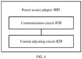
- Fig. 4 is a schematic diagram of a power adapter according to an embodiment of the present disclosure.
- the power adapter 400 as shown in Fig. 4 is configured for coupling with a mobile terminal via a USB interface.
- a power line located in the USB interface is configured for charging the mobile terminal by the power adapter 400
- a data line located in the USB interface is configured for establishing a communication between the power adapter 400 and the mobile terminal.
- the power adapter 400 supports an common charging mode and a fast charging mode, and a charging current under the fast charging mode is greater than a charging current under the common charging mode.
- the power adapter 400 comprises:
- the power adapter instead of blindly increasing an output current to fast charge the mobile terminal, the power adapter fast charges the mobile terminal under the fast charging mode only after receiving the first instruction of the mobile terminal, thereby improving the security of the fast charging process, compared to related art.
- the communication circuit 410 is further configured for receiving a second instruction sent by the mobile terminal through the data line in the USB interface, the second instruction being configured for indicating a charging voltage corresponding to the fast charging mode.
- the communication circuit 410 is further configured for receiving a third instruction sent by the mobile terminal through the data line in the USB interface, the third instruction being configured for indicating the charging current corresponding to the fast charging mode.
- the communication circuit 410 is further configured for receiving a fourth instruction sent by the mobile terminal through the data line in the USB interface during a period of charging the mobile terminal by the power adapter 400 under the fast charging mode, the fourth instruction being configured for indicating a current voltage of the battery in the mobile terminal; and the current adjusting circuit 420 is configured for adjusting the charging current based on the current voltage of the battery in the mobile terminal.
- the current adjusting circuit 420 is configured for adjusting the charging current of the power adapter 400 to the charging current corresponding to the current voltage of the battery, based on the current voltage of the battery, and the preset correspondence between the battery voltage and the charging current.
- the communication circuit 410 is further configured for receiving a fourth instruction sent by the mobile terminal through the data line in the USB interface during a period of charging the mobile terminal by the power adapter 400 under the fast charging mode, the fourth instruction being configured for indicating a current voltage of the battery in the mobile terminal; the power adapter 400 determines whether there is a poor connection between the power adapter 400 and the mobile terminal based on the charging voltage from the power adapter and the current voltage of the battery.
- the units described as separate units may be or may not be physically separated, and components shown as units may be or may not be physical units, that is to say, may be in one place, or may be distributed in several network units. A part or all of the units may be selected according to actual requirements to achieve the purpose of the solution of the present embodiments.
- various functional units in the embodiments of the present disclosure may be integrated into one processing unit, or various functional units each may exist physically separately or two or more units may be integrated into one unit.
- the functions are realized in a form of functional software units and may be sold or configured as stand-alone products, they may be stored in a computer-readable storage medium. Based on such understanding, the spirit of the technical solution of the present disclosure, or a part of the technical solution that contributes to related art or a certain part of the technical solution may be embodied in a form of software product.
- the computer software product may be stored in a storage medium, and comprise a plurality of instructions configured to instruct a computer device (personal computer, server, or network device) to execute all or a part of steps of various embodiments of the present disclosure.
- the storage medium described above comprises various medium storing program codes, such as a U-disk, a mobile hard disk, a read-only memory (ROM), a random access memory (RAM), a disc, a compact disc and so on.
Landscapes
- Engineering & Computer Science (AREA)
- Power Engineering (AREA)
- Theoretical Computer Science (AREA)
- Physics & Mathematics (AREA)
- General Physics & Mathematics (AREA)
- General Engineering & Computer Science (AREA)
- Human Computer Interaction (AREA)
- Charge And Discharge Circuits For Batteries Or The Like (AREA)
- Telephone Function (AREA)
- Secondary Cells (AREA)
Abstract
Description
- The present disclosure relates to the field of battery charging, and more particularly, to a fast charging method, a power adapter and a mobile terminal using the same.
- Currently, mobile terminals (such as smart phones) are increasingly favored by consumers; however, generally, the mobile terminals need to be frequently recharged due to their great power consumption. With the increasement of the battery capacity of the mobile terminals, it takes more time to fully charge the battery. Accordingly, how to shorten the charging time has been a major concern to be solved.
- In related art, in order to shorten the charging time, it is a common method to directly increase an output current of a power adapter regardless of the capacity of a mobile terminal, such that the mobile terminal may be overloaded to cause overheating or even burning, thereby shortening the life span of the mobile terminal.
- Embodiments of the present disclosure provide a fast charging method, a power adapter and a mobile terminal, in order to improve the security of fast charging process.
- A first aspect provides a fast charging method, wherein the method is executed by a mobile terminal, the mobile terminal is coupled to a power adapter via a USB (Universal Serial Bus) interface; a power line located in the USB interface is configured for charging the mobile terminal, a data line located in the USB interface is configured for establishing a communication between the power adapter and the mobile terminal; the mobile terminal supports an common charging mode and a fast charging mode, and a charging current under the fast charging mode is greater than a charging current under the common charging mode; the method comprises: sending, by the mobile terminal, a first instruction to the power adapter through the data line in the USB interface, the first instruction being configured for instructing the power adapter to start the fast charging mode; and receiving, by the mobile terminal, a charging current corresponding to the fast charging mode from the power adapter, so as to charge a battery in the mobile terminal.
- In conjunction with the first aspect, in an embodiment of the first aspect, before receiving, by the mobile terminal, the charging current corresponding to the fast charging mode from the power adapter, so as to charge the battery in the mobile terminal, the method further comprises: sending, by the mobile terminal, a second instruction to the power adapter through the data line in the USB interface, the second instruction being configured for indicating a charging voltage corresponding to the fast charging mode.
- In conjunction with the first aspect or any one of the above embodiments, in another embodiment of the first aspect, before receiving, by the mobile terminal, the charging current corresponding to the fast charging mode from the power adapter, so as to charge the battery in the mobile terminal, the method further comprises: sending, by the mobile terminal, a third instruction to the power adapter through the data line in the USB interface, the third instruction being configured for indicating the charging current corresponding to the fast charging mode.
- In conjunction with the first aspect or any one of the above embodiments, in another embodiment of the first aspect, the method further comprises: sending, by the mobile terminal, a fourth instruction to the power adapter through the data line in the USB interface during a period of charging the mobile terminal by the power adapter under the fast charging mode, the fourth instruction being configured for indicating a current voltage of the battery in the mobile terminal such that the power adapter adjusts the charging current based on the current voltage of the battery, or determines whether a connection to the USB interface is abnormal based on the charging voltage from the power adapter and the current voltage of the battery.
- A second aspect provides a fast charging method, wherein the method is executed by a power adapter, the power adapter is coupled to a mobile terminal via a USB (Universal Serial Bus) interface; a power line located in the USB interface is configured for charging the mobile terminal by the power adapter, a data line located in the USB interface is configured for establishing a communication between the power adapter and the mobile terminal; the mobile terminal supports an common charging mode and a fast charging mode, and a charging current under the fast charging mode is greater than a charging current under the common charging mode; the method comprises: receiving, by the power adapter, a first instruction sent by the mobile terminal through the data line in the USB interface, the first instruction being configured for instructing the power adapter to start the fast charging mode; and adjusting, by the power adapter, the charging current to a current corresponding to the fast charging mode, to charge the mobile terminal.
- In conjunction with the second aspect, in an embodiment of the second aspect, before adjusting, by the power adapter, the charging current to the current corresponding to the fast charging mode, to charge the mobile terminal, the method further comprises: receiving, by the power adapter, a second instruction sent by the mobile terminal through the data line in the USB interface, the second instruction being configured for indicating a charging voltage corresponding to the fast charging mode.
- In conjunction with the second aspect or any one of the above embodiments, in another embodiment of the second aspect, before adjusting, by the power adapter, the charging current to the current corresponding to the fast charging mode, to charge the mobile terminal, the method further comprises: receiving, by the power adapter, a third instruction sent by the mobile terminal through the data line in the USB interface, the third instruction being configured for indicating the charging current corresponding to the fast charging mode.
- In conjunction with the second aspect or any one of the above embodiments, in another embodiment of the second aspect, the method further comprises: receiving, by the power adapter, a fourth instruction sent by the mobile terminal through the data line in the USB interface during a period of charging the mobile terminal by the power adapter under the fast charging mode, the fourth instruction being configured for indicating a current voltage of the battery in the mobile terminal; and adjusting, by the power adapter, the charging current based on the current voltage of the battery in the mobile terminal.
- In conjunction with the second aspect or any one of the above embodiments, in another embodiment of the second aspect, adjusting, by the power adapter, the charging current based on the current voltage of the battery in the mobile terminal comprises: adjusting, by the power adapter, the charging current of the power adapter to the charging current corresponding to the current voltage of the battery, based on the current voltage of the battery, and the preset correspondence between the battery voltage and the charging current.
- In conjunction with the second aspect or any one of the above embodiments, in another embodiment of the second aspect, the method further comprises: receiving, by the power adapter, a fourth instruction sent by the mobile terminal through the data line in the USB interface during a period of charging the mobile terminal by the power adapter under the fast charging mode, the fourth instruction being configured for indicating a current voltage of the battery in the mobile terminal; and determining, by the power adapter, whether a connection to the USB interface is abnormal based on the charging voltage from the power adapter and the current voltage of the battery.
- The third aspect provides a mobile terminal, wherein the mobile terminal is configured for coupling with a power adapter via a USB (Universal Serial Bus) interface; a power line located in the USB interface is configured for charging the mobile terminal, a data line located in the USB interface is configured for establishing a communication between the power adapter and the mobile terminal; the mobile terminal supports an common charging mode and a fast charging mode, and a charging current under the fast charging mode is greater than a charging current under the common charging mode; the mobile terminal comprises: a communication unit configured for sending a first instruction to the power adapter through the data line in the USB interface, the first instruction being configured for instructing the power adapter to start the fast charging mode; and a charging unit configured for receiving a charging current corresponding to the fast charging mode from the power adapter, so as to charge a battery in the mobile terminal.
- In conjunction with the third aspect, in an embodiment of the third aspect, the communication unit is further configured for sending a second instruction to the power adapter through the data line in the USB interface, the second instruction being configured for indicating a charging voltage corresponding to the fast charging mode.
- In conjunction with the third aspect or any one of the above embodiments, in another embodiment of the third aspect, the communication unit is further configured for sending a third instruction to the power adapter through the data line in the USB interface, the third instruction being configured for indicating the charging current corresponding to the fast charging mode.
- In conjunction with the third aspect or any one of the above embodiments, in another embodiment of the third aspect, the communication unit is further configured for sending a fourth instruction to the power adapter through the data line in the USB interface during a period of charging the mobile terminal by the power adapter under the fast charging mode, the fourth instruction being configured for indicating a current voltage of the battery in the mobile terminal such that the power adapter adjusts the charging current based on the current voltage of the battery, or determines whether a connection to the USB interface is abnormal based on the charging voltage from the power adapter and the current voltage of the battery.
- The fourth aspect provides a power adapter, wherein the power adapter is configured for coupling with a mobile terminal via a USB (Universal Serial Bus) interface; a power line located in the USB interface is configured for charging the mobile terminal by the power adapter, a data line located in the USB interface is configured for establishing a communication between the power adapter and the mobile terminal; the mobile terminal supports an common charging mode and a fast charging mode, and a charging current under the fast charging mode is greater than a charging current under the common charging mode; the power adapter comprises: a communication unit configured for receiving a first instruction sent by the mobile terminal through the data line in the USB interface, the first instruction being configured for instructing the power adapter to start the fast charging mode; and a current adjusting unit configured for adjusting a charging current to a current corresponding to the fast charging mode, to charge the mobile terminal.
- In conjunction with the fourth aspect, in an embodiment of the fourth aspect, the communication unit is further configured for receiving a second instruction sent by the mobile terminal through the data line in the USB interface, the second instruction being configured for indicating a charging voltage corresponding to the fast charging mode.
- In conjunction with the fourth aspect or any one of the above embodiments, in another embodiment of the fourth aspect, the communication unit is further configured for receiving a third instruction sent by the mobile terminal through the data line in the USB interface, the third instruction being configured for indicating the charging current corresponding to the fast charging mode.
- In conjunction with the fourth aspect or any one of the above embodiments, in another embodiment of the fourth aspect, the communication unit is further configured for receiving a fourth instruction sent by the mobile terminal through the data line in the USB interface during a period of charging the mobile terminal by the power adapter under the fast charging mode, the fourth instruction being configured for indicating a current voltage of the battery in the mobile terminal; and the current adjusting unit is configured for adjusting the charging current based on the current voltage of the battery in the mobile terminal.
- In conjunction with the fourth aspect or any one of the above embodiments, in another embodiment of the fourth aspect, the current adjusting unit is configured for adjusting the charging current of the power adapter to the charging current corresponding to the current voltage of the battery, based on the current voltage of the battery, and the preset correspondence between the battery voltage and the charging current.
- In conjunction with the fourth aspect or any one of the above embodiments, in another embodiment of the fourth aspect, the communication unit is further configured for receiving a fourth instruction sent by the mobile terminal through the data line in the USB interface during a period of charging the mobile terminal by the power adapter under the fast charging mode, the fourth instruction being configured for indicating a current voltage of the battery in the mobile terminal; the power adapter determines whether a connection to the USB interface is abnormal based on the charging voltage from the power adapter and the current voltage of the battery.
- In the embodiments of the present disclosure, instead of blindly increasing an output current to fast charge the mobile terminal, the power adapter fast charges the mobile terminal under the fast charging mode only after receiving the first instruction of the mobile terminal, thereby improving the security of the fast charging process, compared to related art.
- In order to more clearly illustrate technical solutions according to embodiments of the present disclosure, accompanying drawings configured for the embodiments of the present disclosure will be briefly introduced hereinafter. Apparently, the accompanying drawings described below merely show some embodiments of the present disclosure, and persons skilled in the art may derive other drawings from these accompanying drawings without creative efforts.
-
Fig. 1 is a schematic flowchart of a fast charging method according to an embodiment of the present disclosure. -
Fig. 2 is a schematic flowchart of a fast charging method according to an embodiment of the present disclosure. -
Fig. 3 is a schematic block diagram of a mobile terminal according to an embodiment of the present disclosure. -
Fig. 4 is a schematic block diagram of a power adapter according to an embodiment of the present disclosure. - In conjunction with the drawings in the embodiments of the present disclosure, a clear, complete description for the technical solutions in the embodiments of the present disclosure is provided below. Apparently, the described embodiments are a part rather than all of the embodiments of the present disclosure. All other embodiments derived by persons skilled in the art from the embodiments of the present disclosure without creative efforts should fall within the protection scope of the present disclosure.
-
Fig. 1 is a schematic flowchart of a fast charging method according to an embodiment of the present disclosure. The method as shown inFig. 1 is executed by a mobile terminal, the mobile terminal is coupled to a power adapter via a Universal Serial Bus (USB) interface. The USB interface may be an ordinary USB interface, or may be a micro USB interface. A power line located in the USB interface is configured for charging the mobile terminal. The power line in the USB interface may be a VBus line and/or a ground line in the USB interface. A data line located in the USB interface is configured for establishing a communication between the power adapter and the mobile terminal. The data line may be a D+ line and/or a D- line in the USB interface. The so-called bidirectional communication may refer to information exchange between the power adapter and the mobile terminal. The mobile terminal supports an common charging mode and a fast charging mode, and a charging current under the fast charging mode is greater than a charging current under the common charging mode. For example, the charging current in the common charging mode is generally less than 2.5A, and the charging current in the fast charging mode may be greater than 3A. - The method as shown in
Fig. 1 comprises: - Step 110: the mobile terminal sends a first instruction to the power adapter through the data line in the USB interface, the first instruction being configured for instructing the power adapter to start the fast charging mode.
- It should be understood that, before
step 110, the mobile terminal may determine whether to be fast charged, based on current power, current voltage of a battery, or operating state of the mobile terminal, or the like. - Step 120: the mobile terminal receives a charging current corresponding to the fast charging mode from the power adapter, so as to charge a battery in the mobile terminal.
- In the embodiments of the present disclosure, instead of blindly increasing an output current to fast charge the mobile terminal, the power adapter fast charges the mobile terminal under the fast charging mode only after receiving the first instruction of the mobile terminal, thereby improving the security of the fast charging process, compared to related art.
- In at least one embodiment, before receiving, by the mobile terminal, the charging current corresponding to the fast charging mode from the power adapter, so as to charge the battery in the mobile terminal, the method further comprises: sending, by the mobile terminal, a second instruction to the power adapter through the data line in the USB interface, the second instruction being configured for indicating a charging voltage corresponding to the fast charging mode.
- It should be understood that, the charging voltage corresponding to the fast charging mode may be a preset charging voltage of the power adapter, or may be a charging voltage indicated through the second instruction by the mobile terminal. In at least one embodiment, the mobile terminal may determine the charging voltage corresponding to the fast charging mode based on its operating parameters, such as battery power, voltage, and temperature and so on.
- In at least one embodiment, before receiving, by the mobile terminal, the charging current corresponding to the fast charging mode from the power adapter, so as to charge the battery in the mobile terminal, the method further comprises: sending, by the mobile terminal, a third instruction to the power adapter through the data line in the USB interface, the third instruction being configured for indicating the charging current corresponding to the fast charging mode.
- It should be understood that, the charging current corresponding to the fast charging mode may be a preset charging current of the power adapter, or may be a charging current indicated through the third instruction by the mobile terminal. In at least one embodiment, the mobile terminal may determine the charging current corresponding to the fast charging mode based on its operating parameters, such as battery power, voltage, and temperature and so on.
- In at least one embodiment, the method as shown in
Fig. 1 may further comprise: sending, by the mobile terminal, a fourth instruction to the power adapter through the data line in the USB interface during a period of charging the mobile terminal by the power adapter under the fast charging mode, the fourth instruction being configured for indicating a current voltage of the battery in the mobile terminal such that the power adapter adjusts the charging current based on the current voltage of the battery, or determines whether a connection to the USB interface is abnormal based on the charging voltage from the power adapter and the current voltage of the battery. - In at least one embodiment, the power adapter may determine impedance of the whole circuit based on a voltage drop between its output voltage and battery voltage obtained, and determine a connection to the USB interface is abnormal when the impedance of the circuit is greater than a predetermined threshold.
- In the above, in conjunction with
Fig. 1 , from the mobile terminal's perspective, a detailed description for the fast charging method according to the embodiment of the present disclosure is provided. Moreover, in conjunction withFig. 2 , from the power adapter's perspective, a description for the fast charging method according to an embodiment of the present disclosure is provided hereinafter. - It should be understood that, the interactions, relevant features, functions and so on of the power adapter and the mobile terminal described from the mobile terminal's perspective are corresponding to those described from the power adapter's perspective, and thus repeated description is omitted appropriately for simplicity.
-
Fig. 2 is a schematic flowchart of a fast charging method according to an embodiment of the present disclosure. The method as shown inFig. 2 is executed by a power adapter, the mobile terminal is coupled to a mobile terminal via a USB interface. A power line located in the USB interface is configured for charging the mobile terminal by the power adapter, and a data line located in the USB interface is configured for establishing a communication between the power adapter and the mobile terminal. The mobile terminal supports an common charging mode and a fast charging mode, and a charging current under the fast charging mode is greater than a charging current under the common charging mode. The method as shown inFig. 2 comprises: - Step 210: the power adapter receives a first instruction sent by the mobile terminal through the data line in the USB interface, the first instruction being configured for instructing the power adapter to start the fast charging mode.
- Step 220: the power adapter adjusts the charging current to a current corresponding to the fast charging mode, to charge the mobile terminal.
- In the embodiments of the present disclosure, instead of blindly increasing an output current to fast charge the mobile terminal, the power adapter fast charges the mobile terminal under the fast charging mode only after receiving the first instruction of the mobile terminal, thereby improving the security of the fast charging process, compared to related art..
- In at least one embodiment, before the power adapter adjusts the charging current to the current corresponding to the fast charging mode, to charge the mobile terminal, the method as shown in
Fig. 2 may further comprise: receiving, by the power adapter, a second instruction sent by the mobile terminal through the data line in the USB interface, the second instruction being configured for indicating a charging voltage corresponding to the fast charging mode. - In at least one embodiment, before the power adapter adjusts the charging current to the current corresponding to the fast charging mode, to charge the mobile terminal, the method as shown in
Fig. 2 may further comprise: receiving, by the power adapter, a third instruction sent by the mobile terminal through the data line in the USB interface, the third instruction being configured for indicating the charging current corresponding to the fast charging mode. - In at least one embodiment, the method as shown in
Fig. 2 may further comprise: receiving, by the power adapter, a fourth instruction sent by the mobile terminal through the data line in the USB interface during a period of charging the mobile terminal by the power adapter under the fast charging mode, the fourth instruction being configured for indicating a current voltage of the battery in the mobile terminal; and adjusting, by the power adapter, the charging current based on the current voltage of the battery in the mobile terminal. - In at least one embodiment, adjusting, by the power adapter, the charging current based on the current voltage of the battery in the mobile terminal comprises: adjusting, by the power adapter, the charging current of the power adapter to the charging current corresponding to the current voltage of the battery, based on the current voltage of the battery, and the preset correspondence between the battery voltage and the charging current.
- In at least one embodiment, the method as shown in
Fig. 2 may further comprise: receiving, by the power adapter, a fourth instruction sent by the mobile terminal through the data line in the USB interface during a period of charging the mobile terminal by the power adapter under the fast charging mode, the fourth instruction being configured for indicating a current voltage of the battery in the mobile terminal; and determining, by the power adapter, whether a connection to the USB interface is abnormal based on the charging voltage from the power adapter and the current voltage of the battery. - In the above, in conjunction with
Fig. 1 and Fig. 2 , a detailed description for the fast charging method according to the embodiment of the present disclosure is provided. Moreover, in conjunction withFig. 3 andFig. 4 , a detailed description for a mobile terminal and a power adapter according to an embodiment of the present disclosure is provided hereinafter. It should be understood that, the mobile terminal as shown inFig. 3 may realize each of the steps as shown inFig. 1 to Fig. 2 performed by a mobile terminal, and the power adapter as shown inFig. 4 may realize each of the steps as shown inFig. 1 to Fig. 2 performed by a power adapter, which is not described in detail to avoid repetition. -
Fig. 3 is a schematic block diagram of a mobile terminal according to an embodiment of the present disclosure. Amobile terminal 300 as shown inFig. 3 is configured for coupling with a power adapter via a USB interface. A power line located in the USB interface is configured for charging themobile terminal 300, and a data line located in the USB interface is configured for establishing a communication between the power adapter and themobile terminal 300. Themobile terminal 300 supports an common charging mode and a fast charging mode, and a charging current under the fast charging mode is greater than a charging current under the common charging mode. - The
mobile terminal 300 comprises: - A
communication circuit 310 configured for sending a first instruction to the power adapter through the data line in the USB interface, the first instruction being configured for instructing the power adapter to start the fast charging mode; and - A charging
circuit 320 configured for receiving a charging current corresponding to the fast charging mode from the power adapter, so as to charge a battery in themobile terminal 300. - In the embodiments of the present disclosure, instead of blindly increasing an output current to fast charge the mobile terminal, the power adapter fast charges the mobile terminal under the fast charging mode only after receiving the first instruction of the mobile terminal, thereby improving the security of the fast charging process, compared to related art..
- In at least one embodiment, the
communication circuit 310 is further configured for sending a second instruction to the power adapter through the data line in the USB interface, the second instruction being configured for indicating a charging voltage corresponding to the fast charging mode. - In at least one embodiment, the
communication circuit 310 is further configured for sending a third instruction to the power adapter through the data line in the USB interface, the third instruction being configured for indicating the charging current corresponding to the fast charging mode. - In at least one embodiment, the
communication circuit 310 is further configured for sending a fourth instruction to the power adapter through the data line in the USB interface during a period of charging themobile terminal 300 by the power adapter under the fast charging mode, the fourth instruction being configured for indicating a current voltage of the battery in themobile terminal 300 such that the power adapter adjusts the charging current based on the current voltage of the battery, or determines whether a connection to the USB interface is abnormal based on the charging voltage from the power adapter and the current voltage of the battery. -
Fig. 4 is a schematic diagram of a power adapter according to an embodiment of the present disclosure. Thepower adapter 400 as shown inFig. 4 is configured for coupling with a mobile terminal via a USB interface. A power line located in the USB interface is configured for charging the mobile terminal by thepower adapter 400, and a data line located in the USB interface is configured for establishing a communication between thepower adapter 400 and the mobile terminal. Thepower adapter 400 supports an common charging mode and a fast charging mode, and a charging current under the fast charging mode is greater than a charging current under the common charging mode. - The
power adapter 400 comprises: - A
communication circuit 410 configured for receiving a first instruction sent by the mobile terminal through the data line in the USB interface, the first instruction being configured for instructing the power adapter to start the fast charging mode; and - A current adjusting circuit 420 configured for adjusting a charging current to a current corresponding to the fast charging mode, to charge the mobile terminal.
- In the embodiments of the present disclosure, instead of blindly increasing an output current to fast charge the mobile terminal, the power adapter fast charges the mobile terminal under the fast charging mode only after receiving the first instruction of the mobile terminal, thereby improving the security of the fast charging process, compared to related art..
- In at least one embodiment, the
communication circuit 410 is further configured for receiving a second instruction sent by the mobile terminal through the data line in the USB interface, the second instruction being configured for indicating a charging voltage corresponding to the fast charging mode. - In at least one embodiment, the
communication circuit 410 is further configured for receiving a third instruction sent by the mobile terminal through the data line in the USB interface, the third instruction being configured for indicating the charging current corresponding to the fast charging mode. - In at least one embodiment, the
communication circuit 410 is further configured for receiving a fourth instruction sent by the mobile terminal through the data line in the USB interface during a period of charging the mobile terminal by thepower adapter 400 under the fast charging mode, the fourth instruction being configured for indicating a current voltage of the battery in the mobile terminal; and the current adjusting circuit 420 is configured for adjusting the charging current based on the current voltage of the battery in the mobile terminal. - In at least one embodiment, the current adjusting circuit 420 is configured for adjusting the charging current of the
power adapter 400 to the charging current corresponding to the current voltage of the battery, based on the current voltage of the battery, and the preset correspondence between the battery voltage and the charging current. - In at least one embodiment, the
communication circuit 410 is further configured for receiving a fourth instruction sent by the mobile terminal through the data line in the USB interface during a period of charging the mobile terminal by thepower adapter 400 under the fast charging mode, the fourth instruction being configured for indicating a current voltage of the battery in the mobile terminal; thepower adapter 400 determines whether there is a poor connection between thepower adapter 400 and the mobile terminal based on the charging voltage from the power adapter and the current voltage of the battery. - Persons skilled in the art should appreciate that units and programming steps of various examples described in the embodiments of the present disclosure can be realized by electronic hardware or a combination of computer software and electronic hardware. Whether these functions are realized by hardware or software depends on particular applications and design constraint conditions of technical solutions. For each particular application, persons skilled in the art can employ different methods to realize described functions, but this realization should fall into the scope of the present disclosure.
- Persons skilled in the art can clearly understand that specific operating processes of the above described systems, devices, and units may be understood by referring to the corresponding processes of the above process embodiments which will not be repeated herein for convenience and simplicity.
- In several embodiments provided by the present disclosure, it should be understood that the disclosed systems, devices, and methods can be implemented in other ways. The apparatus embodiments described above are only illustrative. For example, a division into the units is only a division based on logic functions, and may be a division in other ways when actually implementing. For example, several units or assemblies may be combined or may be integrated into another system, or some features may be ignored, or not executed. On the other hand, mutual coupling or direct coupling or communication connection illustrated or discussed herein may be indirect coupling or communication connection through certain interfaces, devices, or units, and may be in a form of electricity, machine, or the like.
- The units described as separate units may be or may not be physically separated, and components shown as units may be or may not be physical units, that is to say, may be in one place, or may be distributed in several network units. A part or all of the units may be selected according to actual requirements to achieve the purpose of the solution of the present embodiments.
- Additionally, various functional units in the embodiments of the present disclosure may be integrated into one processing unit, or various functional units each may exist physically separately or two or more units may be integrated into one unit.
- If the functions are realized in a form of functional software units and may be sold or configured as stand-alone products, they may be stored in a computer-readable storage medium. Based on such understanding, the spirit of the technical solution of the present disclosure, or a part of the technical solution that contributes to related art or a certain part of the technical solution may be embodied in a form of software product. The computer software product may be stored in a storage medium, and comprise a plurality of instructions configured to instruct a computer device (personal computer, server, or network device) to execute all or a part of steps of various embodiments of the present disclosure. The storage medium described above comprises various medium storing program codes, such as a U-disk, a mobile hard disk, a read-only memory (ROM), a random access memory (RAM), a disc, a compact disc and so on.
- The foregoing descriptions are merely preferred embodiments of the present disclosure, rather than limiting the protection scope of the present disclosure. Any person skilled in the art could readily conceive modifications or substitutions within the technical scope of the present disclosure, and these modifications or substitutions should fall within the protection scope of the present disclosure. Therefore, the protection scope of the present disclosure should be limited by the protection scope of the claims.
Claims (20)
- A fast charging method, wherein the method is executed by a mobile terminal, the mobile terminal is coupled to a power adapter via a USB (Universal Serial Bus) interface; a power line located in the USB interface is configured for charging the mobile terminal, a data line located in the USB interface is configured for establishing a communication between the power adapter and the mobile terminal; the mobile terminal supports an common charging mode and a fast charging mode, and a charging current under the fast charging mode is greater than a charging current under the common charging mode; the method comprises:sending, by the mobile terminal, a first instruction to the power adapter through the data line in the USB interface, the first instruction being configured for instructing the power adapter to start the fast charging mode; andreceiving, by the mobile terminal, a charging current corresponding to the fast charging mode from the power adapter, so as to charge a battery in the mobile terminal.
- The method according to claim 1, wherein before receiving, by the mobile terminal, the charging current corresponding to the fast charging mode from the power adapter, so as to charge the battery in the mobile terminal, the method further comprises:sending, by the mobile terminal, a second instruction to the power adapter through the data line in the USB interface, the second instruction being configured for indicating a charging voltage corresponding to the fast charging mode.
- The method according to claim 1 or 2, wherein before receiving, by the mobile terminal, the charging current corresponding to the fast charging mode from the power adapter, so as to charge the battery in the mobile terminal, the method further comprises:sending, by the mobile terminal, a third instruction to the power adapter through the data line in the USB interface, the third instruction being configured for indicating the charging current corresponding to the fast charging mode.
- The method according to any one of claims 1 to 3, wherein the method further comprises: sending, by the mobile terminal, a fourth instruction to the power adapter through the data line in the USB interface during a period of charging the mobile terminal by the power adapter under the fast charging mode, the fourth instruction being configured for indicating a current voltage of the battery in the mobile terminal such that the power adapter adjusts the charging current based on the current voltage of the battery, or determines whether a connection to the USB interface is abnormal based on the charging voltage from the power adapter and the current voltage of the battery.
- A fast charging method, wherein the method is executed by a power adapter, the power adapter is coupled to a mobile terminal via a USB (Universal Serial Bus) interface; a power line located in the USB interface is configured for charging the mobile terminal by the power adapter, a data line located in the USB interface is configured for establishing a communication between the power adapter and the mobile terminal; the mobile terminal supports an common charging mode and a fast charging mode, and a charging current under the fast charging mode is greater than a charging current under the common charging mode; the method comprises:receiving, by the power adapter, a first instruction sent by the mobile terminal through the data line in the USB interface, the first instruction being configured for instructing the power adapter to start the fast charging mode; andadjusting, by the power adapter, the charging current to a current corresponding to the fast charging mode, to charge the mobile terminal.
- The method according to claim 5, wherein before adjusting, by the power adapter, the charging current to the current corresponding to the fast charging mode, to charge the mobile terminal, the method further comprises:receiving, by the power adapter, a second instruction sent by the mobile terminal through the data line in the USB interface, the second instruction being configured for indicating a charging voltage corresponding to the fast charging mode.
- The method according to claim 5 or 6, wherein before adjusting, by the power adapter, the charging current to the current corresponding to the fast charging mode, to charge the mobile terminal, the method further comprises:receiving, by the power adapter, a third instruction sent by the mobile terminal through the data line in the USB interface, the third instruction being configured for indicating the charging current corresponding to the fast charging mode.
- The method according to any one of claims 5 to 7, wherein the method further comprises:receiving, by the power adapter, a fourth instruction sent by the mobile terminal through the data line in the USB interface during a period of charging the mobile terminal by the power adapter under the fast charging mode, the fourth instruction being configured for indicating a current voltage of the battery in the mobile terminal; andadjusting, by the power adapter, the charging current based on the current voltage of the battery in the mobile terminal.
- The method according to claim 8, wherein adjusting, by the power adapter, the charging current based on the current voltage of the battery in the mobile terminal comprises:adjusting, by the power adapter, the charging current of the power adapter to the charging current corresponding to the current voltage of the battery, based on the current voltage of the battery, and the preset correspondence between the battery voltage and the charging current.
- The method according to any one of claims 5 to 9, wherein the method further comprises:receiving, by the power adapter, a fourth instruction sent by the mobile terminal through the data line in the USB interface during a period of charging the mobile terminal by the power adapter under the fast charging mode, the fourth instruction being configured for indicating a current voltage of the battery in the mobile terminal; anddetermining, by the power adapter, whether a connection to the USB interface is abnormal based on the charging voltage from the power adapter and the current voltage of the battery.
- A mobile terminal, wherein the mobile terminal is configured for coupling with a power adapter via a USB (Universal Serial Bus) interface; a power line located in the USB interface is configured for charging the mobile terminal, a data line located in the USB interface is configured for establishing a communication between the power adapter and the mobile terminal; the mobile terminal supports an common charging mode and a fast charging mode, and a charging current under the fast charging mode is greater than a charging current under the common charging mode; the mobile terminal comprises:a communication unit configured for sending a first instruction to the power adapter through the data line in the USB interface, the first instruction being configured for instructing the power adapter to start the fast charging mode; anda charging unit configured for receiving a charging current corresponding to the fast charging mode from the power adapter, so as to charge a battery in the mobile terminal.
- The mobile terminal according to claim 11, wherein the communication unit is further configured for sending a second instruction to the power adapter through the data line in the USB interface, the second instruction being configured for indicating a charging voltage corresponding to the fast charging mode.
- The mobile terminal according to claim 11 or 12, wherein the communication unit is further configured for sending a third instruction to the power adapter through the data line in the USB interface, the third instruction being configured for indicating the charging current corresponding to the fast charging mode.
- The mobile terminal according to any one of claims 11 to 13, wherein the communication unit is further configured for sending a fourth instruction to the power adapter through the data line in the USB interface during a period of charging the mobile terminal by the power adapter under the fast charging mode, the fourth instruction being configured for indicating a current voltage of the battery in the mobile terminal such that the power adapter adjusts the charging current based on the current voltage of the battery, or determines whether a connection to the USB interface is abnormal based on the charging voltage from the power adapter and the current voltage of the battery.
- A power adapter, wherein the power adapter is configured for coupling with a mobile terminal via a USB (Universal Serial Bus) interface; a power line located in the USB interface is configured for charging the mobile terminal by the power adapter, a data line located in the USB interface is configured for establishing a communication between the power adapter and the mobile terminal; the mobile terminal supports an common charging mode and a fast charging mode, and a charging current under the fast charging mode is greater than a charging current under the common charging mode; the power adapter comprises:a communication unit configured for receiving a first instruction sent by the mobile terminal through the data line in the USB interface, the first instruction being configured for instructing the power adapter to start the fast charging mode; anda current adjusting unit configured for adjusting a charging current to a current corresponding to the fast charging mode, to charge the mobile terminal.
- The power adapter according to claim 15, wherein the communication unit is further configured for receiving a second instruction sent by the mobile terminal through the data line in the USB interface, the second instruction being configured for indicating a charging voltage corresponding to the fast charging mode.
- The power adapter according to claim 15 or 16, wherein the communication unit is further configured for receiving a third instruction sent by the mobile terminal through the data line in the USB interface, the third instruction being configured for indicating the charging current corresponding to the fast charging mode.
- the power adapter according to any one of claims 15 to 17, wherein the communication unit is further configured for receiving a fourth instruction sent by the mobile terminal through the data line in the USB interface during a period of charging the mobile terminal by the power adapter under the fast charging mode, the fourth instruction being configured for indicating a current voltage of the battery in the mobile terminal; and
the current adjusting unit is configured for adjusting the charging current based on the current voltage of the battery in the mobile terminal. - The power adapter according to claim 18, wherein the current adjusting unit is configured for adjusting the charging current of the power adapter to the charging current corresponding to the current voltage of the battery, based on the current voltage of the battery, and the preset correspondence between the battery voltage and the charging current.
- The power adapter according to any one of claims 15 to 19, wherein the communication unit is further configured for receiving a fourth instruction sent by the mobile terminal through the data line in the USB interface during a period of charging the mobile terminal by the power adapter under the fast charging mode, the fourth instruction being configured for indicating a current voltage of the battery in the mobile terminal; the power adapter determines whether a connection to the USB interface is abnormal based on the charging voltage from the power adapter and the current voltage of the battery.
Applications Claiming Priority (3)
| Application Number | Priority Date | Filing Date | Title |
|---|---|---|---|
| PCT/CN2014/090847 WO2016074160A1 (en) | 2014-11-11 | 2014-11-11 | Communication method, power adaptor and terminal |
| PCT/CN2015/074050 WO2016074391A1 (en) | 2014-11-11 | 2015-03-11 | Power adapter and terminal |
| PCT/CN2015/078905 WO2016074459A1 (en) | 2014-11-11 | 2015-05-13 | Fast charging method, power source adapter and mobile terminal |
Publications (2)
| Publication Number | Publication Date |
|---|---|
| EP3148039A1 true EP3148039A1 (en) | 2017-03-29 |
| EP3148039A4 EP3148039A4 (en) | 2018-01-17 |
Family
ID=55953566
Family Applications (3)
| Application Number | Title | Priority Date | Filing Date |
|---|---|---|---|
| EP14905845.5A Active EP3220507B1 (en) | 2014-11-11 | 2014-11-11 | Communication method, power adaptor and terminal |
| EP21190177.2A Pending EP3923443A1 (en) | 2014-11-11 | 2014-11-11 | Communication method, power adaptor and terminal |
| EP15859023.2A Pending EP3148039A4 (en) | 2014-11-11 | 2015-05-13 | Fast charging method, power source adapter and mobile terminal |
Family Applications Before (2)
| Application Number | Title | Priority Date | Filing Date |
|---|---|---|---|
| EP14905845.5A Active EP3220507B1 (en) | 2014-11-11 | 2014-11-11 | Communication method, power adaptor and terminal |
| EP21190177.2A Pending EP3923443A1 (en) | 2014-11-11 | 2014-11-11 | Communication method, power adaptor and terminal |
Country Status (6)
| Country | Link |
|---|---|
| US (3) | US9985449B2 (en) |
| EP (3) | EP3220507B1 (en) |
| JP (1) | JP6475826B2 (en) |
| KR (2) | KR20170020536A (en) |
| CN (4) | CN108667094B (en) |
| WO (2) | WO2016074160A1 (en) |
Cited By (1)
| Publication number | Priority date | Publication date | Assignee | Title |
|---|---|---|---|---|
| EP3754777A4 (en) * | 2018-02-13 | 2021-04-14 | ZTE Corporation | Charging method and apparatus, system, charging circuit, terminal and charging system |
Families Citing this family (8)
| Publication number | Priority date | Publication date | Assignee | Title |
|---|---|---|---|---|
| WO2016074160A1 (en) * | 2014-11-11 | 2016-05-19 | 广东欧珀移动通信有限公司 | Communication method, power adaptor and terminal |
| EP3131171B1 (en) * | 2014-11-11 | 2019-01-30 | Guangdong Oppo Mobile Telecommunications Corp., Ltd | Power adaptor, terminal and charging system |
| WO2016074159A1 (en) * | 2014-11-11 | 2016-05-19 | 广东欧珀移动通信有限公司 | Communication method, power adaptor and terminal |
| PL3214726T3 (en) * | 2016-01-05 | 2019-04-30 | Guangdong Oppo Mobile Telecommunications Corp Ltd | Rapid charging method, mobile terminal and adapter |
| CN107231013B (en) * | 2016-05-24 | 2019-01-15 | 华为技术有限公司 | A kind of method of charging, terminal, charger and system |
| CN209488195U (en) * | 2016-10-12 | 2019-10-11 | Oppo广东移动通信有限公司 | Mobile terminal |
| CN109004710B (en) * | 2018-08-01 | 2021-04-06 | 广州番禺巨大汽车音响设备有限公司 | Sound equipment charging mode switching method and device based on USB (Universal Serial bus) line |
| CN113162199B (en) * | 2021-05-12 | 2023-06-02 | 展讯通信(上海)有限公司 | Charging method and device, and computer readable storage medium |
Family Cites Families (63)
| Publication number | Priority date | Publication date | Assignee | Title |
|---|---|---|---|---|
| JPH06284586A (en) | 1993-03-30 | 1994-10-07 | Toyoda Mach Works Ltd | Power supply apparatus |
| JPH07308031A (en) * | 1994-05-13 | 1995-11-21 | Toshiba Battery Co Ltd | Charger for secondary battery |
| JPH08126221A (en) | 1994-10-27 | 1996-05-17 | Canon Inc | Charger |
| JP2880940B2 (en) | 1995-12-26 | 1999-04-12 | 埼玉日本電気株式会社 | Mobile phone |
| US5764035A (en) | 1996-09-23 | 1998-06-09 | Ericsson Inc. | System and method for automatically enabling rapid charging of a battery in a portable phone |
| EP1107344B1 (en) | 1999-05-17 | 2010-11-03 | Panasonic Corporation | Circuit and device for protecting secondary battery |
| JP4846755B2 (en) | 2002-04-15 | 2011-12-28 | 富士通セミコンダクター株式会社 | Portable electronic devices |
| US7190171B2 (en) | 2002-10-11 | 2007-03-13 | Canon Kabushiki Kaisha | Detecting method and detecting apparatus for detecting internal of rechargeable battery, rechargeable battery pack having said detecting apparatus therein, apparatus having said detecting apparatus therein, program in which said detecting method is incorporated, and medium in which said program is stored |
| GB0313520D0 (en) * | 2003-06-12 | 2003-07-16 | Koninkl Philips Electronics Nv | Wireless battery charger detection and notification |
| KR101011922B1 (en) | 2003-07-31 | 2011-02-01 | 엘지전자 주식회사 | Battery charging apparatus and method thereof |
| JP2007141164A (en) | 2005-11-22 | 2007-06-07 | Sharp Corp | Power supply system, electronic device and power supply tool |
| JP2007189789A (en) | 2006-01-11 | 2007-07-26 | Sanyo Electric Co Ltd | Battery pack and electronic equipment |
| US7531986B2 (en) * | 2006-02-23 | 2009-05-12 | Eveready Battery Company, Inc. | Power supply for battery powered devices |
| JP5020530B2 (en) * | 2006-04-14 | 2012-09-05 | パナソニック株式会社 | Charging method, battery pack and charger thereof |
| US7701168B2 (en) | 2007-03-23 | 2010-04-20 | Sony Ericsson Mobile Communications Ab | Universal serial bus charger device |
| KR101494900B1 (en) | 2007-07-25 | 2015-02-24 | 삼성전자주식회사 | Mobile phone and method for charging through discernment charging cable |
| CN101399386B (en) | 2007-09-25 | 2012-04-18 | 南京德朔实业有限公司 | Lithium battery pack and charging method thereof |
| US20120153891A1 (en) * | 2007-11-07 | 2012-06-21 | Yung-Tai Yang | Portable electronic apparatus and circuit and method for charging rechargeable battery thereof |
| CN101651403A (en) * | 2008-08-13 | 2010-02-17 | 鸿富锦精密工业(深圳)有限公司 | Power supply equipment, power utilization equipment, power supply and utilization system, as well as power supply method and power utilization method |
| CN101771178A (en) | 2008-12-29 | 2010-07-07 | 深圳易拓科技有限公司 | Charging method adopting USB interfaces |
| WO2010084599A1 (en) | 2009-01-23 | 2010-07-29 | トヨタ自動車株式会社 | Charge control device |
| US8386814B2 (en) * | 2009-07-20 | 2013-02-26 | Texas Instruments Incorporated | Continuous monitoring of a USB client for battery charging specification charging capacity |
| DE102009036816A1 (en) | 2009-08-10 | 2011-02-17 | Rwe Ag | Control of charging stations |
| US8350522B2 (en) | 2010-03-10 | 2013-01-08 | Apple Inc. | External power source voltage drop compensation for portable devices |
| US8717044B2 (en) * | 2010-04-23 | 2014-05-06 | Apple Inc. | Charging systems with direct charging port support and extended capabilities |
| CN102270860B (en) * | 2010-06-07 | 2015-08-19 | 技嘉科技股份有限公司 | Filling soon of intelligent mobile phone is put |
| JP2012143092A (en) | 2011-01-04 | 2012-07-26 | Kimitake Utsunomiya | Charging ac adapter |
| JP5668542B2 (en) | 2011-03-11 | 2015-02-12 | 日産自動車株式会社 | Vehicle charging control device |
| JP2012223077A (en) | 2011-04-14 | 2012-11-12 | Kyocera Corp | Charging system |
| US8836287B2 (en) * | 2011-05-03 | 2014-09-16 | Apple Inc. | Time-domain multiplexing of power and data |
| CN102820682B (en) | 2011-06-09 | 2016-01-20 | 中兴通讯股份有限公司 | A kind of communicated by USB interface and be external equipment charging device and method |
| CN102270680B (en) | 2011-08-25 | 2013-08-28 | 广东保威新能源有限公司 | Spiral pile capable of adjusting eccentrically-installed vertical post |
| CN102427260A (en) | 2011-12-02 | 2012-04-25 | 苏州冠硕新能源有限公司 | Charging management system and charging holder using same |
| KR20130083116A (en) | 2012-01-12 | 2013-07-22 | 삼성전자주식회사 | Recharging control system and method for battery of electronic device |
| JP5773920B2 (en) | 2012-03-19 | 2015-09-02 | ルネサスエレクトロニクス株式会社 | Charger |
| CN102868820A (en) * | 2012-09-19 | 2013-01-09 | 中兴通讯股份有限公司 | Mobile terminal, primary data communication device and mobile terminal charging system and method |
| WO2014077978A1 (en) * | 2012-11-14 | 2014-05-22 | Apple Inc. | High voltage charging for a portable device |
| CN102957193B (en) | 2012-11-19 | 2015-12-23 | 中兴通讯股份有限公司 | A kind of charging management method, device and system |
| CN103066340B (en) | 2012-12-17 | 2015-08-12 | 中兴通讯股份有限公司 | charging method, mobile terminal and adapter |
| JP5495407B1 (en) * | 2012-12-21 | 2014-05-21 | パナソニック株式会社 | Electronic device, charger and electronic device system |
| KR20140120699A (en) | 2013-04-04 | 2014-10-14 | 삼성전자주식회사 | Control Method for Charging and Electronic Device, and Charging Device supporting the same |
| US9356460B2 (en) * | 2013-08-05 | 2016-05-31 | Texas Instruments Incorporated | Method and apparatus of fast battery charging with universal high power input source |
| JP5949701B2 (en) | 2013-08-20 | 2016-07-13 | 富士通株式会社 | Charging system and processing device |
| CN203617746U (en) | 2013-11-26 | 2014-05-28 | 比亚迪股份有限公司 | Electric vehicle, charging device, and charging control guide circuit of electric vehicle |
| CN103730933A (en) * | 2013-12-23 | 2014-04-16 | 联想(北京)有限公司 | Charging method and electronic devices |
| CN203722283U (en) | 2013-12-27 | 2014-07-16 | 中兴通讯股份有限公司 | Charging cable and charging system |
| CN103762702B (en) * | 2014-01-28 | 2015-12-16 | 广东欧珀移动通信有限公司 | Charging device of electronic appliances and power supply adaptor thereof |
| CN108448667B (en) | 2014-01-28 | 2022-07-12 | Oppo广东移动通信有限公司 | Terminal, power adapter and charging abnormity processing method |
| CN203747454U (en) * | 2014-01-28 | 2014-07-30 | 广东欧珀移动通信有限公司 | Electronic device charging control device |
| CN103762690B (en) * | 2014-01-28 | 2016-08-24 | 广东欧珀移动通信有限公司 | Charging system |
| CN106253427B (en) * | 2014-01-28 | 2018-05-29 | 广东欧珀移动通信有限公司 | Terminal and its battery charging control device and method |
| CN103746434B (en) * | 2014-01-28 | 2016-04-06 | 广东欧珀移动通信有限公司 | Charging method and system |
| CN104124483B (en) * | 2014-05-23 | 2016-05-04 | 东莞市钜大电子有限公司 | A kind of portable power source fast charge method and system |
| CN104065147B (en) * | 2014-06-27 | 2017-06-06 | 宇龙计算机通信科技(深圳)有限公司 | A kind of charging adapter, terminal, charge control method |
| CN104065126B (en) * | 2014-06-27 | 2017-01-25 | 宇龙计算机通信科技(深圳)有限公司 | Charger, terminal and charging method |
| CN104092274A (en) * | 2014-07-29 | 2014-10-08 | 深圳市至高通信技术发展有限公司 | Intelligent charger with output voltage changing function |
| CN104135057B (en) | 2014-08-13 | 2016-05-18 | 宇龙计算机通信科技(深圳)有限公司 | terminal, charger and charging method |
| CN104393628B (en) | 2014-08-29 | 2017-02-01 | 展讯通信(上海)有限公司 | USB charger, mobile terminal and charging control method |
| CN104393627B (en) | 2014-08-29 | 2017-06-30 | 展讯通信(上海)有限公司 | USB charger, mobile terminal and charge control method |
| CN104269893B (en) | 2014-09-11 | 2017-08-04 | 深圳天珑无线科技有限公司 | Charge control method and charging system |
| WO2016074159A1 (en) * | 2014-11-11 | 2016-05-19 | 广东欧珀移动通信有限公司 | Communication method, power adaptor and terminal |
| EP3131171B1 (en) * | 2014-11-11 | 2019-01-30 | Guangdong Oppo Mobile Telecommunications Corp., Ltd | Power adaptor, terminal and charging system |
| WO2016074160A1 (en) * | 2014-11-11 | 2016-05-19 | 广东欧珀移动通信有限公司 | Communication method, power adaptor and terminal |
-
2014
- 2014-11-11 WO PCT/CN2014/090847 patent/WO2016074160A1/en active Application Filing
- 2014-11-11 CN CN201810461219.XA patent/CN108667094B/en active Active
- 2014-11-11 CN CN201480073122.1A patent/CN105900312B/en active Active
- 2014-11-11 EP EP14905845.5A patent/EP3220507B1/en active Active
- 2014-11-11 US US15/122,459 patent/US9985449B2/en active Active
- 2014-11-11 EP EP21190177.2A patent/EP3923443A1/en active Pending
-
2015
- 2015-05-13 WO PCT/CN2015/078905 patent/WO2016074459A1/en active Application Filing
- 2015-05-13 CN CN201580004522.1A patent/CN106030962B/en active Active
- 2015-05-13 JP JP2017518081A patent/JP6475826B2/en active Active
- 2015-05-13 KR KR1020177003394A patent/KR20170020536A/en active Application Filing
- 2015-05-13 EP EP15859023.2A patent/EP3148039A4/en active Pending
- 2015-05-13 KR KR1020197027788A patent/KR102135606B1/en active IP Right Grant
- 2015-05-13 CN CN201810716984.1A patent/CN108988415A/en active Pending
-
2017
- 2017-01-13 US US15/405,771 patent/US10454288B2/en active Active
-
2018
- 2018-11-21 US US16/198,662 patent/US10326291B2/en active Active
Cited By (1)
| Publication number | Priority date | Publication date | Assignee | Title |
|---|---|---|---|---|
| EP3754777A4 (en) * | 2018-02-13 | 2021-04-14 | ZTE Corporation | Charging method and apparatus, system, charging circuit, terminal and charging system |
Also Published As
| Publication number | Publication date |
|---|---|
| JP6475826B2 (en) | 2019-02-27 |
| KR20190110160A (en) | 2019-09-27 |
| WO2016074160A1 (en) | 2016-05-19 |
| CN108988415A (en) | 2018-12-11 |
| EP3923443A1 (en) | 2021-12-15 |
| US20190157886A1 (en) | 2019-05-23 |
| KR20170020536A (en) | 2017-02-22 |
| US10454288B2 (en) | 2019-10-22 |
| EP3220507B1 (en) | 2021-09-01 |
| CN108667094B (en) | 2020-01-14 |
| CN105900312A (en) | 2016-08-24 |
| CN108667094A (en) | 2018-10-16 |
| CN106030962A (en) | 2016-10-12 |
| US20170149252A1 (en) | 2017-05-25 |
| EP3148039A4 (en) | 2018-01-17 |
| KR102135606B1 (en) | 2020-07-21 |
| US20170237273A1 (en) | 2017-08-17 |
| US10326291B2 (en) | 2019-06-18 |
| JP2017531984A (en) | 2017-10-26 |
| CN105900312B (en) | 2018-05-29 |
| EP3220507A4 (en) | 2018-04-04 |
| WO2016074459A1 (en) | 2016-05-19 |
| CN106030962B (en) | 2018-09-04 |
| EP3220507A1 (en) | 2017-09-20 |
| US9985449B2 (en) | 2018-05-29 |
Similar Documents
| Publication | Publication Date | Title |
|---|---|---|
| US10326291B2 (en) | Quick charging method, power adapter and mobile terminal | |
| US10910853B2 (en) | Quick charging method, power adapter and mobile terminal | |
| EP3131171B1 (en) | Power adaptor, terminal and charging system | |
| CN109149694B (en) | Charging method, charging device, power supply equipment and terminal to be charged | |
| JP6275856B2 (en) | Terminal, power adapter and charging error processing method | |
| CN108988417B (en) | Power adapter and terminal | |
| CN103730933A (en) | Charging method and electronic devices | |
| CN106063073B (en) | Fast charge method, power supply adaptor and mobile terminal | |
| EP3101770B1 (en) | Power adapter and terminal | |
| CN110582917A (en) | Charging method, terminal and computer storage medium |
Legal Events
| Date | Code | Title | Description |
|---|---|---|---|
| STAA | Information on the status of an ep patent application or granted ep patent |
Free format text: STATUS: THE INTERNATIONAL PUBLICATION HAS BEEN MADE |
|
| PUAI | Public reference made under article 153(3) epc to a published international application that has entered the european phase |
Free format text: ORIGINAL CODE: 0009012 |
|
| STAA | Information on the status of an ep patent application or granted ep patent |
Free format text: STATUS: REQUEST FOR EXAMINATION WAS MADE |
|
| 17P | Request for examination filed |
Effective date: 20161222 |
|
| AK | Designated contracting states |
Kind code of ref document: A1 Designated state(s): AL AT BE BG CH CY CZ DE DK EE ES FI FR GB GR HR HU IE IS IT LI LT LU LV MC MK MT NL NO PL PT RO RS SE SI SK SM TR |
|
| AX | Request for extension of the european patent |
Extension state: BA ME |
|
| A4 | Supplementary search report drawn up and despatched |
Effective date: 20171215 |
|
| RIC1 | Information provided on ipc code assigned before grant |
Ipc: H02J 7/04 20060101ALI20171211BHEP Ipc: H02J 7/00 20060101AFI20171211BHEP Ipc: H01M 10/44 20060101ALI20171211BHEP |
|
| DAV | Request for validation of the european patent (deleted) | ||
| DAX | Request for extension of the european patent (deleted) | ||
| RAP1 | Party data changed (applicant data changed or rights of an application transferred) |
Owner name: GUANGDONG OPPO MOBILE TELECOMMUNICATIONS CORP., LT |
|
| STAA | Information on the status of an ep patent application or granted ep patent |
Free format text: STATUS: EXAMINATION IS IN PROGRESS |
|
| 17Q | First examination report despatched |
Effective date: 20200218 |
|
| STAA | Information on the status of an ep patent application or granted ep patent |
Free format text: STATUS: EXAMINATION IS IN PROGRESS |
|
| STAA | Information on the status of an ep patent application or granted ep patent |
Free format text: STATUS: EXAMINATION IS IN PROGRESS |