EP3147264B1 - Systeme und verfahren zur mechanischen kombination von losem schrott - Google Patents
Systeme und verfahren zur mechanischen kombination von losem schrott Download PDFInfo
- Publication number
- EP3147264B1 EP3147264B1 EP16189756.6A EP16189756A EP3147264B1 EP 3147264 B1 EP3147264 B1 EP 3147264B1 EP 16189756 A EP16189756 A EP 16189756A EP 3147264 B1 EP3147264 B1 EP 3147264B1
- Authority
- EP
- European Patent Office
- Prior art keywords
- station
- scrap
- feed scrap
- feed
- twisting
- Prior art date
- Legal status (The legal status is an assumption and is not a legal conclusion. Google has not performed a legal analysis and makes no representation as to the accuracy of the status listed.)
- Active
Links
Images


Classifications
-
- C—CHEMISTRY; METALLURGY
- C03—GLASS; MINERAL OR SLAG WOOL
- C03B—MANUFACTURE, SHAPING, OR SUPPLEMENTARY PROCESSES
- C03B1/00—Preparing the batches
- C03B1/02—Compacting the glass batches, e.g. pelletising
-
- B—PERFORMING OPERATIONS; TRANSPORTING
- B30—PRESSES
- B30B—PRESSES IN GENERAL
- B30B3/00—Presses characterised by the use of rotary pressing members, e.g. rollers, rings, discs
- B30B3/04—Presses characterised by the use of rotary pressing members, e.g. rollers, rings, discs co-operating with one another, e.g. with co-operating cones
-
- C—CHEMISTRY; METALLURGY
- C03—GLASS; MINERAL OR SLAG WOOL
- C03B—MANUFACTURE, SHAPING, OR SUPPLEMENTARY PROCESSES
- C03B5/00—Melting in furnaces; Furnaces so far as specially adapted for glass manufacture
- C03B5/005—Melting in furnaces; Furnaces so far as specially adapted for glass manufacture of glass-forming waste materials
-
- C—CHEMISTRY; METALLURGY
- C03—GLASS; MINERAL OR SLAG WOOL
- C03B—MANUFACTURE, SHAPING, OR SUPPLEMENTARY PROCESSES
- C03B5/00—Melting in furnaces; Furnaces so far as specially adapted for glass manufacture
- C03B5/16—Special features of the melting process; Auxiliary means specially adapted for glass-melting furnaces
- C03B5/235—Heating the glass
- C03B5/2356—Submerged heating, e.g. by using heat pipes, hot gas or submerged combustion burners
-
- Y—GENERAL TAGGING OF NEW TECHNOLOGICAL DEVELOPMENTS; GENERAL TAGGING OF CROSS-SECTIONAL TECHNOLOGIES SPANNING OVER SEVERAL SECTIONS OF THE IPC; TECHNICAL SUBJECTS COVERED BY FORMER USPC CROSS-REFERENCE ART COLLECTIONS [XRACs] AND DIGESTS
- Y02—TECHNOLOGIES OR APPLICATIONS FOR MITIGATION OR ADAPTATION AGAINST CLIMATE CHANGE
- Y02P—CLIMATE CHANGE MITIGATION TECHNOLOGIES IN THE PRODUCTION OR PROCESSING OF GOODS
- Y02P40/00—Technologies relating to the processing of minerals
- Y02P40/50—Glass production, e.g. reusing waste heat during processing or shaping
Definitions
- SCM submerged combustion melting
- the matrix can include glass and/or inorganic non-metallic raw feedstocks such as rock (basalt) and mineral wool (stone wool). Regardless of the material utilized, it is heated at a high efficiency via the intimate contact with the combustion gases and melts into a matrix.
- Using submerged combustion burners produces violent turbulence of the molten matrix and results in a high degree of mechanical energy in the submerged combustion melter.
- the raw material is introduced so as to ensure sufficient time to melt the material into the matrix and to avoid cool spots in the matrix,
- US2009317319 A1 teaches in a method including the steps of collecting waste, compressing and twisting it into rope form and feeding the rope into an incinerator in which implicitly some melting processes take place.
- the technology relates to a method according to claim 1 including: collecting, at a collection station, loose feed scrap; feeding the loose feed scrap to a compression station where the loose feed scrap is compressed into a compressed feed scrap having a density higher than a density of the loose feed scrap; feeding the loose feed scrap to a twisting station where the loose feed scrap is twisted into a bound feed scrap having a substantially continuous length greater than a length of the loose feed scrap; feeding at least one of the compressed feed scrap and the bound feed scrap to an exit station, wherein the at least one of the compressed feed scrap and the bound feed scrap exit the exit station as a rope of scrap; and delivering the rope of scrap to a melter system.
- the compression station and the twisting station are a combined station.
- the compression station includes a plurality of compression stations and the twisting station includes a plurality of twisting stations.
- at least one of the feeding operations include moving a material via at least one conveyor.
- the collection station includes a plurality of conveyors configured to move the loose feed scrap.
- the plurality of conveyors of the collection station are configured to move in a generally forward direction and a generally backward direction.
- the combined station includes a plurality of rollers.
- the plurality of rollers are disposed at an angle to a general direction of movement of the loose feed scrap.
- the rope of feed scrap is delivered to a melter system at an entry port of an SCM melt vessel, wherein the SCM port has a port temperature lower than a temperature of the SCM melt vessel.
- the technology relates to a method according to claim 1 including: collecting a feed scrap; twisting the feed scrap; compressing the feed scrap; and feeding the twisted feed scrap and the compressed feed scrap into a melter system.
- the twisting operation and compression operation are performed substantially simultaneously.
- the method includes forming the compressed feed scrap and the twisted feed scrap into a substantially continuous rope.
- the forming operation is performed substantially simultaneously with the twisting operation and the compressing operation.
- the rope is fed into the melter system during the feeding operation.
- the twisting operation and the compression operation are performed in a plurality of discrete operations between the collecting operation and the feeding operation.
- the twisting operation and the compression operation are performed at a first simultaneous operation to produce a first twisted, compressed feed scrap output having a first diameter and a first density.
- the twisting operation and the compression operation are performed at a second simultaneous operation downstream of the first simultaneous operation to produce a second twisted, compressed feed scrap output having a second diameter less than the first diameter and second density greater than the first density.
- the technology relates to a method according to claim 1 of forming a rope material from a loose feed scrap, the method including: substantially simultaneously advancing, twisting, and compressing the loose scrap feed until the rope material is formed.
- the technology relates to a system according to claim 14 including: a collection station for collecting feed scrap; an advancing mechanism for advancing the feed scrap through the system; a first twisting station for twisting the feed scrap; a first compressing station for compressing the feed scrap; and a feed station for feeding the feed scrap into a melter system.
- the first twisting station and the first compressing station are contained in a first combination station.
- the system includes a second twisting station and a second compressing station contained in a second combination station.
- the first combination station is disposed at a first end of the advancing mechanism and the second combination station is disposed at a second end of the advancing mechanism.
- the feed scrap collected at the collecting station is a loose feed scrap and wherein the feed scrap fed from the feed station is a roped feed scrap.
- at least one of the twisting station and the compressing station include a plurality of rollers.
- the plurality of rollers each include a plurality of teeth projecting from the rollers.
- FIG. 1 depicts a side sectional view of a melter system 100 that may be utilized in conjunction with examples of the technology described herein.
- the melter system 100 is a submerged combustion melter (SCM) and is described in more detail in U.S. Patent Application Publication No. 2013/0283861 .
- SCM submerged combustion melter
- Melter apparatus or melt vessel 101 of FIG. 1 includes a floor 102, a roof or ceiling 104, a feed end wall 106A, a first portion of an exit end wall 106B, and a second portion of the exit end wall 106C.
- Each of the floor 102, the roof 104, and walls 106A, 106B, and 106C comprise a metal shell 117 and a refractory panel 109, some or all of which may be fluid-cooled.
- Exit end wall portion 106C may form an angle with respect to a skimmer 118.
- the melt vessel 101 may be fluid cooled by using a gaseous, liquid, or combination thereof, heat transfer media.
- the wall may have a refractory liner at least between the panels and the molten glass.
- Certain systems may cool various components by directing a heat transfer fluid through those components.
- the refractory cooled-panels of the walls, the fluid-cooled skimmer, the fluid-cooled dam, the walls of the fluid-cooled transition channel, and the burners may be cooled by a heat transfer fluid selected from the group consisting of gaseous, liquid, or combinations of gaseous and liquid compositions that function or are capable of being modified to function as a heat transfer fluid.
- Gaseous heat transfer fluids may be selected from air, including ambient air and treated air (for air treated to remove moisture), inert inorganic gases, such as nitrogen, argon, and helium, inert organic gases such as fluoro-, chloro-and chlorofluorocarbons, including perfluorinated versions, such as tetrafluoromethane, and hexafluoroethane, and tetrafluoroethylene, and the like, and mixtures of inert gases with small portions of non-inert gases, such as hydrogen.
- inert inorganic gases such as nitrogen, argon, and helium
- inert organic gases such as fluoro-, chloro-and chlorofluorocarbons, including perfluorinated versions, such as tetrafluoromethane, and hexafluoroethane, and tetrafluoroethylene, and the like
- Heat transfer liquids may be selected from inert liquids, which may be organic, inorganic, or some combination thereof, for example, salt solutions, glycol solutions, oils and the like.
- Other possible heat transfer fluids include water, steam (if cooler than the oxygen manifold temperature), carbon dioxide, or mixtures thereof with nitrogen.
- Heat transfer fluids may be compositions including both gas and liquid phases, such as the higher chlorofluorocarbons.
- the melt vessel 101 further includes an exhaust stack 108, and openings 110 for submerged combustion burners 112, which create during operation a highly turbulent melt matrix indicated at 114.
- Highly turbulent melt matrix 114 may have an uneven top surface 115 due to the nature of submerged combustion.
- An average level 107 is illustrated with a dashed line.
- burners 112 are positioned to emit combustion products into molten matrix in the melting zone 114 in a fashion so that the gases penetrate the melt generally perpendicularly to floor 102. In other examples, one or more burners 112 may emit combustion products into the melt at an angle to floor 102.
- combustion gases emanate from burners 112 under the level of a molten matrix.
- the burners 112 may be floor-mounted, wall-mounted, or in melter examples comprising more than one submerged combustion burner, any combination thereof (for example, two floor mounted burners and one wall mounted burner).
- These combustion gases may be substantially gaseous mixtures of combusted fuel, any excess oxidant, and combustion products, such as oxides of carbon (such as carbon monoxide, carbon dioxide), oxides of nitrogen, oxides of sulfur, and water.
- Combustion products may include liquids and solids, for example soot and unburned liquid fuels.
- a burner 112 may be an air-fuel burner that combusts one or more fuels with only air, or an oxy-fuel burner that combusts one or more fuels with either oxygen alone, or employs oxygen-enriched air, or some other combination of air and oxygen, including combustion burners where the primary oxidant is air, and secondary and tertiary oxidants are oxygen.
- Burners may be comprised of metal, ceramic, ceramic-lined metal, or combination thereof.
- Air in an air-fuel mixture may include ambient air as well as gases having the same molar concentration of oxygen as air.
- Oxygen-enriched air having an oxygen concentration greater than 121 mole percent may be used.
- Oxygen may include pure oxygen, such as industrial grade oxygen, food grade oxygen, and cryogenic oxygen.
- Oxygen-enriched air may have 50 mole percent or more oxygen, and in certain examples may be 90 mole percent or more oxygen.
- Oxidants such as air, oxygen-enriched air, and pure oxygen may be supplied from a pipeline, cylinders, storage facility, cryogenic air separation unit, membrane permeation separator, or adsorption unit.
- the fuel burned by the burners may be a combustible composition (either in gaseous, liquid, or solid form, or any flowable combination of these) having a major portion of, for example, methane, natural gas, liquefied natural gas, propane, atomized oil, powders or the like.
- Contemplated fuels may include minor amounts of non-fuels therein, including oxidants, for purposes such as premixing the fuel with the oxidant, or atomizing liquid fuels.
- At least some of the burners may be mounted below the melt vessel, and in certain examples the burners may be positioned in one or more parallel rows substantially perpendicular to a longitudinal axis of the melt vessel. In certain examples, the number of burners in each row may be proportional to width of the vessel. In certain examples the depth of the vessel may decrease as width of the vessel decreases. In certain other examples, an intermediate location may comprise a constant width zone positioned between an expanding zone and a narrowing zone of the vessel, in accordance with U.S. Patent Application Publication No. 2011/0308280 , the disclosure of which is hereby incorporated by reference herein in its entirety.
- the initial raw material can be introduced into melt vessel 101 on a batch, semi-continuous or continuous basis.
- a port 105 is arranged at end 106A of melt vessel 101 through which the initial raw material is introduced by a feeder 134.
- a batch blanket 136 may form along wall 106A, as illustrated.
- Feed port 105 may be positioned above the average matrix melt level, indicated by dashed line 107.
- the amount of the initial raw material introduced into melt vessel 101 is generally a function of, for example, the capacity and operating conditions of melt vessel 101 as well as the rate at which the molten material is removed from melt vessel 101.
- submerged combustion burners may produce violent turbulence of the molten matrix and may result in a high degree of mechanical energy (e.g., vibration V in FIG. 1 ) in the submerged combustion melter that, without modification, is undesirably transferred to the conditioning channel. Vibration may be due to one or more impacts from sloshing of the molten matrix, pulsing of the submerged combustion burners, popping of large bubbles above submerged burners, ejection of the molten matrix from main matrix melt against the walls and ceiling of melt vessel 101, and the like.
- Vibration may be due to one or more impacts from sloshing of the molten matrix, pulsing of the submerged combustion burners, popping of large bubbles above submerged burners, ejection of the molten matrix from main matrix melt against the walls and ceiling of melt vessel 101, and the like.
- Melter exit structure 128 comprises a fluid-cooled transition channel 30, having generally rectangular cross-section in melt vessel 101, although any other cross-section would suffice, such as hexagonal, trapezoidal, oval, circular, and the like. Regardless of cross-sectional shape, fluid-cooled transition channel 130 is configured to form a frozen matrix layer or highly viscous matrix layer, or combination thereof, on inner surfaces of fluid-cooled transition channel 130 and thus protect melter exit structure 128 from the mechanical energy imparted from the melt vessel 101 to melter exit structure 128.
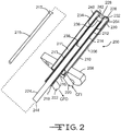
- FIG. 2 depicts a side sectional view of a burner 200 that may be utilized in conjunction with the examples of the technology described herein.
- the burner 200 is an SCM burner having a fluid-cooled portion 202 having a burner tip 204 attached to a burner body 206.
- a burner main flange 208 connects the burner to an SCM superstructure or flange, illustrated below.
- Burner body 206 has an external conduit 210, a first internal conduit 212, a second internal conduit 214, and end plates 216, 218.
- a coolant fluid inlet conduit 220 is provided, along with a coolant fluid exit conduit 222, allowing ingress of a cool coolant fluid as indicated by an arrow CFI, and warmed coolant fluid egress, as indicated by an arrow CFO, respectively.
- a first annulus 211 is thus formed between substantially concentric external conduit 210 and first internal conduit 212, and a second annulus 213 is formed between substantially concentric first and second internal conduits 212, 214.
- a proximal end 224 of second internal conduit 214 may be sized to allow insertion of a fuel or oxidant conduit 215 (depending on the burner arrangement), which may or may not include a distal end nozzle 217.
- conduit 215 and optional nozzle 217 are inserted internal of second internal conduit 214, a third annulus is formed there between.
- oxidant flows through the third annulus, while one or more fuels flow through conduit 215, entering through a port 244.
- one or more fuels flow through the third annulus, while oxidant flows through conduit 215, entering through port 244.
- the fluid-cooled portion 202 of the burner 200 includes a ceramic or other material insert 226 fitted to the distal end of first internal conduit 212.
- Insert 226 has a shape similar to but smaller than burner tip 204, allowing coolant fluid to pass between burner tip 204 and insert 226, thus cooling burner tip 204.
- Burner tip 204 includes an inner wall 228, an outer wall 230, and a crown 232 connecting inner wall 228 and outer wall 230.
- welds at locations 234 and 236, and optionally at 238, 240 and 242 connect burner tip 204 to external conduit 210 and second internal conduit 214, using conventional weld materials to weld together similar base metal parts, such as carbon steel, stainless steel, or titanium.
- the initial raw material may include any material suitable for forming a molten matrix, such as glass and/or inorganic non-metallic feedstocks such as rock (basalt) and mineral wool (stone wool).
- glass matrices specifically, limestone, glass, sand, soda ash, feldspar and mixtures thereof can be utilized.
- a glass composition for producing glass fibers is "E-glass," which typically includes 52-56% SiO 2 , 12-16% Al 2 O 3 , 0-0.8% Fe 2 O 3 , 16-25% CaO, 0-6% MgO, 0-10% B 2 O 3 , 0-2% Na 2 O+K 2 O, 0-1.5% TiO 2 and 0-1% F 2 .
- Other glass compositions may be used, such as those described in U.S. Published Patent Application No. 2008/0276652 .
- the initial raw material can be provided in any form such as, for example, relatively small particles.
- Loose feed scrap can be particularly difficult to feed evenly into the SCM burner vessel.
- Loose feed scrap can include portions of batt glass insulation that is produced during the insulation manufacturing process. The dimensions, densities, shapes, etc. of loose feed scrap can vary within a given volume of material. For example, the loose feed scrap can be cut or trimmed from finished insulation, resulting in oddly-shaped chunks of material that are difficult to introduce in a controlled fashion to the melt vessel.
- the technologies described herein relate to systems and methods utilized to produce substantially consistent (with regard to, e.g., size, density, etc.) masses of feed scrap fiberglass wool for introduction into a melter system.
- the technologies transform disorganized, non-uniform, loose wool or loose feed scrap from a bin and generate a tight, twisted rope of material that is fed into a melt vessel for melting and refining.
- the system produces a continuous, deadened (e.g., non-expanding) rope of material with sufficient size uniformity and feed rate so as not to disrupt stable operation of the melter.
- the rope has sufficient strength to enable a set of rollers to feed the rope into the melter from its exterior, thereby requiring no moving mechanisms inside the melter. If desired, however, static guides can be used.
- the final roller station and entry port in the melter wall may be cooled such that the rope will not begin to melt outside the melter. Additionally, by not melting outside the melter, binder volatiles are not released.
- the entry port in the melter wall may be as small as practical to minimize melter gas emissions through the port.
- the bin disposed at a front end of the system, may incorporate moving walls and a moving bottom surface, as well as constraining conveyors such that a controlled flow of loose wool is fed into twist rollers and/or compression stations having a number of rollers.
- the walls, conveyors, and twisting/compression stations may be independently reversible. Individual reversibility of components helps stretch any heavy or large lumps of wool that would may be drawn into the system from the bin.
- roller stations may influence the final size, limpness, density, and twist imparted in the wool rope.
- a combination station having both twit and compression functionality may incorporate two or more driven rollers.
- Each roller may be disposed at oblique angles to the feed direction, such that the rollers cause both compression of the product and impart twist in it.
- Subsequent roller stations may utilize rollers having more prominent oblique angles, faster drive speed relative to prior stations, smaller rollers, and more closely spaced rollers. This can help further reduce the diameter of, and increase the density of, the finished rope.
- the number of rollers, diameter of rollers, oblique angles of the rollers, roller teeth shape/quantity/spacing, and station-to-station spacing may each affect the degree of twist, rope diameter, and the compression imparted into the material rope (and thus the resulting density thereof).
- the roller stations crush and deaden the material to further diminish the recovery/expansion thereof as it leaves any roller station.
- roller surfaces may both grip and crush the feed scrap, thereby reducing recovery or expansion of the material downstream of any roller station. Additionally, this provides load transfer from the rollers into the material, thereby further feeding the twisted/compressed feed scrap forward to each subsequent station.
- Each roller surface may incorporate hardened teeth, such as carbide, that may enable both the gripping and crushing of the material. The spacing, quantity, shape, and arrangement of such teeth may influence the performance of the rollers.
- Each roller station may utilize a different configuration of such teeth on its rollers. While the described technology utilizes as initial raw material loose feed scrap in the form of bonded and cured batt insulation of virtually any size, the technologies described herein may also utilize feed scrap in the form of unbonded loose fill wool. With these general considerations in mind, specific examples of systems and methods for mechanically binding loose feed scrap are described below.
- FIG. 3 depicts a schematic view of a system 300 for mechanically binding loose scrap.
- the various stations are first described generally below.
- a feed direction D of the material is generally left-to-right in the system 300.
- the system includes a collection station 302, into which loose feed scrap 304 is amassed and collected.
- the loose feed scrap 304 can be dumped into the bin via mechanical equipment or the emptying of containers.
- the feed scrap 304 exits the collection station 302 and enters one or more compression stations 306, 308 that compress the feed scrap 304.
- the compressed feed scrap 304 is moved along an advancing mechanism 310. In general, the advancing mechanism 310 advances the feed scrap 304, generally without significant compression or twisting.
- the feed stock enters a twisting station 312 to twist together the feed scrap 304.
- the feed scrap 304 can then be fed to a combination twisting/compression station 314 that both twists the feed scrap 304 and reduces a thickness thereof simultaneously.
- the feed scrap 304 can be fed through further advancing mechanisms, compression stations, twisting stations, twisting/compression stations, etc., (depicted generally as 316) as required or desired for a particular application.
- the feed scrap is then advanced through an exit station 318 before being fed into an SCM melt vessel 320 as a mechanically bound and twisted rope of material.
- the collection station 302 includes one or more conveyors 322 that form walls and a floor of a bin into which the loose feed scrap is deposited via an open inlet 324.
- These conveyors 322 can be actuated in either in a forward direction (e.g., thus moving the feed scrap in a direction generally towards an outlet 326) or in a rearward direction (e.g., thus moving the feed scrap in a direction generally away from the outlet 326).
- the conveyors 322 advance the feed scrap towards the outlet 326, where they are compressed at the first compression station 306 and the second compression station 308.
- Each compression station 306, 308 may include a plurality of rollers 328 having axes A mounted generally orthogonal to (but offset from) the advancing feed scrap.
- the first compression station 306 includes two rollers 328 (only one of which is depicted) rotating around vertical axes A.
- the second compression station 308 includes two rollers 328 rotating around horizontal axes A. Further details of the rollers 328 are described below.
- the compression stations 306, 308 generally define the outer volume of the feed scrap 304 as it exits the outlet 326.
- the rollers 328 are spaced so as to compress the feed stock into a first volume having first dimensions. These dimensions will be reduced as the feed scrap passes through the remaining stations of the system 300. As such, the density of material will increase within a particular cross section of the feed scrap as it advances through the system 300.
- the compressed feed scrap is then advanced by the advancing mechanism 310, which generally includes a plurality of conveyors 330 that maintain the general outer dimension of the compressed feed stock, but without further mechanical binding actions (such as twisting and compression).
- the advancing mechanism 310 which generally includes a plurality of conveyors 330 that maintain the general outer dimension of the compressed feed stock, but without further mechanical binding actions (such as twisting and compression).
- Conveyors may also be disposed on the sides of the feed scrap, so as to contain and move the material.
- the fixed walls can be located on the sides of the advancing mechanism to prevent loss of material.
- the feed stock next enters a twisting station 312. This feed station includes a number of rollers 332 having axes disposed substantially parallel to the advancing feed scrap. Further details of the rollers 332 are provided below.
- the rollers 332 advance the feed scrap through the twisting station 312 while at the same time twisting the various pieces of feed scrap together into a substantially continuous mass.
- the feed stock forms into a substantially continuous mass by twisting and therefore binding together discrete pieces of loose scrap. Additionally and substantially simultaneously, twisting further binds together individual threads of a single piece of loose scrap. Threads of a first piece of loose scrap may also be twisted with threads of a second piece of loose scrap, further mechanically binding the loose scrap together.
- the feed scrap After passing through the first twisting station 312, the feed scrap now begins to take on the form factor of a bound, substantially continuous rope.
- the feed scrap advances to the twisting/compression station 314 that includes a number of rollers 334 having axes disposed oblique to the advancing feed scrap. Further details of the rollers 334 are provided below. In general, however, the rollers 334 advance the feed scrap through the twisting/compression station 314 while at the same time twisting the various pieces of feed scrap together into a substantially continuous mass.
- the twisting aspect of the station 314 is described above with regard to the actions of station 312.
- the rollers 334 also further compress the scrap as it moves through the twisting/compression station 314. This further binds the mass together, further decreases the dimensions thereof, and as such, further increases the density of a particular cross section thereof.
- the feed scrap mass begins to take on a form having a substantially circular cross section (e.g., similar to that of a rope).
- twisting/compression stations are not necessarily required, but it has been discovered that a plurality of twisting/compression stations may further define and control the dimensions and density of the rope material.
- further advancing mechanisms, compression stations, twisting stations, twist/compression stations, coil stations (in the form of rollers or storage bins), etc. are depicted generally as 316. These may be utilized as required or desired for a particular application. For example, depending on the desired diameter of the rope material, further compression stations may be utilized.
- Systems 300 having a collection station 302 particularly remote from the SCM melter 320 may require additional advancing mechanisms to move the rope material towards melter 320.
- most of the stations may be disposed in a location (e.g., a room) remote from a room containing the SCM melter.
- the rope material may be advanced into the room with the melter for feeding.
- the rope may be stored at a coil station in a coiled configuration and uncoiled as desired to be fed into the melter 320.
- Other configurations are contemplated.
- the exit station 318 defines the approximate end of the system 300 and is used to feed the mechanically bound, twisted/compressed rope material into the SCM melter 320.
- the exit station 318 includes a plurality of rollers 336 disposed widthwise relative to the feed direction of the rope.
- the rollers 336 advance the rope material into an entry port 338 defined by a wall 340 in the SCM melter 320.
- the rollers 336 and entry port 338 may be cooled such that the rope will not begin to melt outside the melter 320.
- the geometry/configuration of the rollers and enclosure (not shown) may be configured to control gases entering or exiting the melter through 338.
- FIG. 4 depicts a method 400 for mechanically binding loose scrap.
- the feed scrap is collected in a substantially loose form.
- the feed scrap is twisted.
- This operation 404 contemplates both twisting discrete pieces of scrap upon themselves, and also contemplates twisting discrete pieces of scrap into other discrete pieces of scrap.
- the scrap is compressed, which increases the density of the material.
- Operations 404 and 406 may be performed at discrete locations at one or more times between the collecting operation 402 and a feeding operation 414 (described below). In another example, both of operations 404 and 406 may be performed in a simultaneous operation 408.
- the individual twisting operation 404, compression operation 406, and/or simultaneous operation 408 may be repeated any number of times, as indicated by loop 410. Indeed, as the feed scrap passes through, e.g., a first simultaneous operation 408, it exits the operation 408 having a first, twisted configuration having a first diameter and a first density. As the simultaneous operation 408 is repeated via loop 410, and the feed scrap passes through a second simultaneous operation 408 downstream of the first simultaneous operation 408, it exits that operation 408 having a second, twisted configuration having a second dimension and a second density. As the feed scrap has been compressed and twisted, the second diameter is generally less than the first diameter, while the second density is generally greater than the first density.
- This feed scrap in the form of a rope, may then be fed into a melter system in operation 414.
- the technologies described herein advance a loose feed scrap in a system that substantially simultaneously twists and compresses the loose feed scrap into a mechanically-bound, rope-like material for delivery to a melt system.
- the twisting and compression operations 404, 406 may be discontinuous, intermittent, or may be performed in opposite directions. This can create partial tears or elongations of the continuous rope, which may help to spread bulges or high density clumps in the feed scrap. Such operations may also create further tension in the rope, deadening of resiliency/recovery, and alignment of the feed scrap within the rope.
- FIG. 5 depicts a method 500 for mechanically binding loose scrap, e.g., with the system of FIG. 3 , and other arrangements based on that system.
- a collection station which may include a number of conveyors to move material within the station, as well as to discharge the material therefrom.
- a station upstream from another station may directly feed material to a downstream station (e.g., without the use of a conveyor).
- loose scrap 504a may be fed as material to a compression station, as depicted in operation 506.
- a compression station disposed immediately downstream of the collection station may help more quickly define and contain the outer dimensions of the mass of material.
- operation 506 immediately following operation 502 may be desirable.
- loose scrap 504b may be fed as material to a twisting station 508.
- the operation of compression and twisting stations are described elsewhere herein.
- compressed scrap 510 may be fed as material to the twisting station in operation 508. This is the configuration previously depicted in FIG. 5 .
- This compressed scrap 510 has a density higher than that of the loose scrap 504a fed into the compression station.
- twisted scrap 512 can be fed as material to the compression station in operation 506.
- This twisted and bound scrap 512 typically has a substantially continuous length greater than that of the longest pieces of loose scrap 504a fed into the twisting station.
- the twisting station and the compression station may be combined into a combination station that performs both functions substantially simultaneously.
- feed scrap may pass through a plurality each of the compression stations and the twisting stations.
- Output material 514 from the compression station and/or the twisting station 508 is fed to an exit station in operation 516 and exits that station as a rope of material 518.
- This rope 518 is delivered in operation 520 to a melter system where it is melted into a matrix.
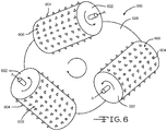
- FIG. 6 depicts front view of a roller station 600 utilized in the system of FIG. 3 . More specifically, in view of the number and orientation of the rollers 602, FIG. 6 depicts a combination twist and compression station 600. Each roller 602 rotates about an axis A, which in the depicted example, is in a counterclockwise direction.
- the rollers 602 include a plurality of teeth 604 extending from an outer surface 606 therefrom. The teeth 604 may have a number of different configurations, as described in more detail below.
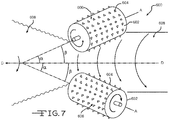
- FIG. 7 depicts a side view of the roller station 600 of FIG. 6 . As can be seen, the rollers 602 are disposed at two angles ⁇ , ⁇ to a direction of travel axis D.
- the direction of travel axis D represents the general direction along which the scrap material 608 moves through the station 600 (and the system generally).
- Scrap material 608 enters the proximity of the rollers 602 and is drawn therethrough by contact with the rollers 602 and the teeth 604, which grip, pull, and twist the scrap material 608 and draw it along the direction of travel axis D.
- the rollers 602 compress and twist the scrap material 608 as it passes through the station 600. This, in turn, increases the density of the material and forms the material into a substantially continuous rope of material.
- Subsequent roller stations may be similarly categorized to further compress and twist the material into a tighter, more dense rope of material.
- Each roller 602 has two oblique angles ⁇ , ⁇ relative to the feed direction D (i.e., coaxial with the approximate rope centerline) such that the rollers 602 cause both compression of the material and impart twist in it.
- the tail end of each roller 602 (the end further downstream along the rope centerline) is closer to the centerline of the rope to amplify compression of the rope as the rope proceeds downstream within any single roller 602.
- the angle ⁇ at which the roller 602 is disposed may be between about 0° to about 45° off the rope axis, preferably 5° to about 20°.
- the rotational axis of the roller 602 is not parallel to the centerline of the rope, so as to impart additional twist as such, this angle ⁇ may be about 0° to about 45° off the rope axis, preferably 5° to about 20°.
- FIG. 8A and 8B depict examples of teeth 700 utilized in the roller stations of FIG. 6 .
- a number of roller stations are utilized, each performing different functions.
- rollers dedicated to compressing the loose scrap rollers dedicated to twisting the loose scrap, and rollers that perform both functions are utilized.
- Each of these types of rollers generally also perform an advancing function, moving the material through a respective station.
- teeth projecting from the rotors can aid in these functions.
- FIGS. 8A and 8B depict such teeth.
- FIG. 8A depicts so called crushing teeth 700.
- FIG. 8B depicts so-called gripping teeth 702.
- crushing and gripping describe generally the primary function of the particular type of teeth 700, 702, but are not intended to be limiting or mutually exclusive. That is, crushing teeth 700 can also perform some gripping function, while gripping teeth 702 can also perform some crushing function. The terms are used to describe the general physical characteristics of the teeth 700, 702 so as to differentiate different types of teeth from each other.
- crushing teeth 700 have a larger diameter ⁇ than the diameter ⁇ of the gripping teeth 702.
- Another distinction is the height H of the crushing teeth 700 above the roller surface 704. That is, the height H of the crushing teeth 700 is generally less than the height H of the gripping teeth 702.
- the taller height of the gripping teeth 702 allows those teeth 702 to penetrate deeper into the material so as to pull and twist the material as the rollers rotate.
- a top surface 708 of the crushing teeth 700 is generally flat. This allows the crushing teeth 700 to push larger quantities of the material together so as to aid in compression thereof.
- a top surface 710 of the gripping teeth 702, however, can have a generally pointed construction, so as to more easily separate and penetrate the material.
Landscapes
- Chemical & Material Sciences (AREA)
- Engineering & Computer Science (AREA)
- Materials Engineering (AREA)
- Organic Chemistry (AREA)
- Mechanical Engineering (AREA)
- Combustion & Propulsion (AREA)
- Processing Of Solid Wastes (AREA)
- Manufacture And Refinement Of Metals (AREA)
- Ropes Or Cables (AREA)
Claims (17)
- Verfahren (400, 500), umfassend:Sammeln eines losen Zufuhrausschusses (402, 502) in Form von gebundener und gehärteter Wärmedämmung von nahezu beliebiger Größe oder in Form von ungebundener, loser Füllungswolle;Verdrillen des Zufuhrausschusses (404, 508);Komprimieren des Zufuhrausschusses (406, 506);Formen des komprimierten Zufuhrausschusses und des verdrillten Zufuhrausschusses zu einem Strang; undZuführen des Strangs in ein Tauchbrenner-Schmelzersystem (414, 520).
- Verfahren (500) nach Anspruch 1, wobei der Verdrillungsvorgang (506) und Komprimierungsvorgang (508) im Wesentlichen gleichzeitig durchgeführt werden.
- Verfahren (400, 500) nach einem der vorstehenden Ansprüche 1 oder 2, weiter umfassend Formen des komprimierten Zufuhrausschusses und des verdrillten Zufuhrausschusses zu einem im Wesentlichen durchgängigen Strang (412, 518).
- Verfahren (400, 500) nach Anspruch 3, wobei der Strang im Laufe des Zuführungsvorgangs (414, 520) in das Schmelzersystem (320) zugeführt wird.
- Verfahren (400) nach Anspruch 1, wobei der Verdrillungsvorgang (404) und der Komprimierungsvorgang (406) in einer Vielzahl diskreter Vorgänge zwischen dem Sammelvorgang (402) und dem Zuführungsvorgang (414) durchgeführt werden.
- Verfahren (400) nach Anspruch 5, wobei der Verdrillungsvorgang (404) und der Komprimierungsvorgang (406) bei einem ersten gleichzeitigen Vorgang (408) durchgeführt werden, um eine erste verdrillte, komprimierte Zufuhrausschussausgabe mit einem ersten Durchmesser und einer ersten Dichte zu produzieren.
- Verfahren (400) nach einem der vorstehenden Ansprüche 5 oder 6, wobei der Verdrillungsvorgang (404) und der Komprimierungsvorgang (406) bei einem zweiten gleichzeitigen Vorgang (410), dem ersten gleichzeitigen Vorgang (408) nachgelagert, durchgeführt werden, um eine verdrillte, komprimierte Zufuhrausschussausgabe mit einem zweiten Durchmesser kleiner als der erste Durchmesser und einer zweiten Dichte größer als die erste Dichte zu produzieren.
- Verfahren (400, 500) nach einem der vorstehenden Ansprüche, umfassend:Sammeln (402, 502), an einer Sammelstation (302), von losem Zufuhrausschuss (304, 504a, 504b);Zuführen des losen Zufuhrausschusses (304, 504a) an eine Komprimierungsstation (306, 308), wo der lose Zufuhrausschuss (304, 504a) zu einem komprimierten Zufuhrausschuss (304, 510) mit einer Dichte höher als eine Dichte des losen Zufuhrausschusses (304, 504a, 504b) komprimiert (406, 506) wird;Zuführen des losen Zufuhrausschusses (304, 504b) an eine Verdrillungsstation (312), wo der lose Zufuhrausschuss (304, 504b) zu einem gebundenen Zufuhrausschuss (304) mit einer im Wesentlichen durchgängigen Länge größer als eine Länge des losen Zufuhrausschusses (304, 504a, 504b) verdrillt (404, 508) wird;Zuführen (516) von mindestens einem von dem komprimierten Zufuhrausschuss (304, 510) und dem gebundenen Zufuhrausschuss (304) an eine Ausgangsstation (318), wobei der mindestens eine des komprimierten Zufuhrausschusses (304, 510) und des gebundenen Zufuhrausschusses (304) die Ausgangsstation (318) als ein Strang von Ausschuss (304, 518) verlässt; undAbliefern des Strangs von Ausschuss (304, 518) an ein Tauchbrenner-Schmelzersystem (100,320).
- Verfahren (400, 500) nach Anspruch 8, wobei die Komprimierungsstation (306, 308) und die Verdrillungsstation (312, 508) eine kombinierte Station (314) sind.
- Verfahren (400, 500) nach Anspruch 9, wobei die kombinierte Station (314) eine Vielzahl von Walzen (602) beinhaltet, wobei die Vielzahl von Walzen (602) zu einer allgemeinen Richtung (D) von Bewegung des losen Zufuhrausschusses (304) vorzugsweise in einem Winkel (α, β) angeordnet ist.
- Verfahren (400, 500) nach einem der Ansprüche 8 bis 10, wobei mindestens einer der Zuführungsvorgänge (414) Bewegen eines Materials (304, 514, 518, 608) mittels mindestens eines Förderbands (322, 330) beinhaltet.
- Verfahren (400, 500) nach einem der vorstehenden Ansprüche 8 bis 11, wobei die Sammelstation (302) eine Vielzahl von Förderbändern (322) beinhaltet, konfiguriert, um den losen Zufuhrausschuss (304) zu bewegen, wobei die Vielzahl von Förderbändern (322) der Sammelstation (302) vorzugsweise konfiguriert ist, um sich in einer allgemeinen Vorwärtsrichtung und einer allgemeinen Rückwärtsrichtung zu bewegen.
- Verfahren (400, 500) nach einem der vorstehenden Ansprüche 8 bis 12, wobei der Strang von Zufuhrausschuss (304, 518) an einer Eingangsöffnung (105, 338) eines Tauchbrenner-Schmelzer-Schmelzgefäßes (101,320) an einem Schmelzersystem (100, 320) abgeliefert wird, wobei die Tauchbrenner-Schmelzeröffnung (105, 338) eine Öffnungstemperatur niedriger als eine Temperatur des Tauchbrenner-Schmelzer-Schmelzgefäßes (101, 320) aufweist.
- System (300), umfassend:eine Sammelstation (302) zum Sammeln von Zufuhrausschuss (304) in Form von gebundener und gehärteter Wärmedämmung von nahezu beliebiger Größe oder in Form von ungebundener, loser Füllungswolle;einen Vorschubmechanismus (310) zum Vorschieben des Zufuhrausschusses (304) durch das System (300) hindurch;eine erste Verdrillungsstation (312) zum Verdrillen des Zufuhrausschusses (304) zu der Form eines Strangs;eine erste Komprimierungsstation (306) zum Komprimieren des Zufuhrausschusses zu der Form eines Strangs; undeine Zufuhrstation zum Zuführen des Strangs von Zufuhrausschuss (304) in ein Tauchbrenner-Schmelzersystem (320).
- System (300) nach Anspruch 14, wobei die erste Verdrillungsstation (312) und die erste Komprimierungsstation (306) in einer ersten Kombinationsstation (314) enthalten sind.
- System (300) nach Anspruch 15, weiter umfassend eine in einer zweiten Kombinationsstation (316) enthaltene zweite Verdrillungsstation und eine zweite Komprimierungsstation (308), wobei die erste Kombinationsstation (314) vorzugsweise an einem ersten Ende des Vorschubmechanismus (310) angeordnet ist und die zweite Kombinationsstation (316) vorzugsweise an einem zweiten Ende des Vorschubmechanismus (310) angeordnet ist.
- System (300) nach einem der vorstehenden Ansprüche 14 bis 16, wobei mindestens eine von der Verdrillungsstation (312) und der Komprimierungsstation (306) eine Vielzahl von Walzen (328, 332, 334, 336, 602) umfassen, wobei die Vielzahl von Walzen (328, 332, 334, 336, 602) vorzugsweise jede eine Vielzahl von Zähnen (604, 700, 702) umfassen, die aus den Walzen (328, 332, 334, 336, 602) herausragen.
Priority Applications (2)
| Application Number | Priority Date | Filing Date | Title |
|---|---|---|---|
| SI201631455T SI3147264T1 (sl) | 2015-09-23 | 2016-09-20 | Sistemi in postopki za mehansko združevanje sipkih odpadkov |
| PL16189756T PL3147264T3 (pl) | 2015-09-23 | 2016-09-20 | Układy i sposoby służące do mechanicznego łączenia luźnego wsadu |
Applications Claiming Priority (1)
| Application Number | Priority Date | Filing Date | Title |
|---|---|---|---|
| US14/862,811 US10081563B2 (en) | 2015-09-23 | 2015-09-23 | Systems and methods for mechanically binding loose scrap |
Publications (3)
| Publication Number | Publication Date |
|---|---|
| EP3147264A2 EP3147264A2 (de) | 2017-03-29 |
| EP3147264A3 EP3147264A3 (de) | 2017-06-28 |
| EP3147264B1 true EP3147264B1 (de) | 2021-12-15 |
Family
ID=57132983
Family Applications (1)
| Application Number | Title | Priority Date | Filing Date |
|---|---|---|---|
| EP16189756.6A Active EP3147264B1 (de) | 2015-09-23 | 2016-09-20 | Systeme und verfahren zur mechanischen kombination von losem schrott |
Country Status (5)
| Country | Link |
|---|---|
| US (2) | US10081563B2 (de) |
| EP (1) | EP3147264B1 (de) |
| CA (1) | CA2940936A1 (de) |
| PL (1) | PL3147264T3 (de) |
| SI (1) | SI3147264T1 (de) |
Families Citing this family (3)
| Publication number | Priority date | Publication date | Assignee | Title |
|---|---|---|---|---|
| GB201801977D0 (en) * | 2018-02-07 | 2018-03-28 | Knauf Insulation Doo Skofja Loka | Recycling |
| US11697608B2 (en) * | 2019-10-01 | 2023-07-11 | Owens-Brockway Glass Container Inc. | Selective chemical fining of small bubbles in glass |
| PL3835269T3 (pl) * | 2019-12-11 | 2022-03-28 | International Partners In Glass Research (Ipgr) E.V. | Sposób i urządzenie do wytwarzania zestawu do wprowadzania do pieca szklarskiego |
Family Cites Families (402)
| Publication number | Priority date | Publication date | Assignee | Title |
|---|---|---|---|---|
| US1875474A (en) | 1932-09-06 | To libbey-owens | ||
| GB191301772A (en) | 1913-01-22 | 1914-01-22 | Louis Frederick Tooth | Improvements in or relating to Gas-fired Furnaces or Kilns. |
| GB191407633A (en) | 1914-03-26 | 1915-03-26 | Louis Frederick Tooth | Improved Gas-fired Furnace for the Cupellation or Refining of Silver, Glass Bending, Enamelling and other like purposes. |
| GB164073A (en) | 1920-01-29 | 1921-05-30 | Morris William Travers | Improvements in furnaces |
| US1636151A (en) | 1922-08-23 | 1927-07-19 | Shaw John Schofield | Furnace for melting and refining glass and other like purposes |
| US1579353A (en) | 1924-11-01 | 1926-04-06 | Good Robert | Water-cooled bridge |
| US1716433A (en) | 1925-03-17 | 1929-06-11 | Ellis Foster Co | Submerged combustion process |
| US1706857A (en) | 1925-08-14 | 1929-03-26 | Hartford Empire Co | Apparatus for the precise determination of the level of glass in alpha furnace |
| US1883023A (en) | 1926-05-11 | 1932-10-18 | Edwin E Slick | Glass furnace |
| US1679295A (en) | 1927-01-13 | 1928-07-31 | Hazel Atlas Glass Co | Bridge wall for glass tanks |
| US1989103A (en) | 1932-02-06 | 1935-01-29 | Laclede Christy Clay Products | Glass melting tank |
| US1944855A (en) | 1932-07-28 | 1934-01-23 | Hartford Empire Co | Method of and apparatus for making glass |
| US1937321A (en) | 1933-01-16 | 1933-11-28 | Hartford Empire Co | Apparatus for making glass |
| US2042560A (en) | 1934-09-28 | 1936-06-02 | Andrew H Stewart | Furnace wall |
| US2064546A (en) | 1935-04-06 | 1936-12-15 | Pittsburgh Plate Glass Co | Glass melting tank |
| US2174533A (en) | 1937-02-23 | 1939-10-03 | Theodore S See | Submerged combustion control system |
| US2269459A (en) | 1937-08-11 | 1942-01-13 | Owens Corning Fiberglass Corp | Tubular fiber |
| US2118479A (en) | 1938-03-24 | 1938-05-24 | Submerged Comb Company Of Amer | Submerged combustion burner |
| US2432942A (en) | 1943-04-05 | 1947-12-16 | Submerged Comb Company Of Amer | Submerged combustion system |
| US2455907A (en) | 1944-04-15 | 1948-12-07 | Owens Corning Fiberglass Corp | Apparatus for melting glass |
| US2718096A (en) | 1947-07-17 | 1955-09-20 | Union Des Verreries Mecaniques | Apparatus for melting glass and the like |
| US2691689A (en) | 1948-01-12 | 1954-10-12 | Saint Gobain | Glass tank furnace and method of operating the same |
| US2679749A (en) | 1948-10-30 | 1954-06-01 | Brockway Glass Co Inc | Molten glass viscosity measuring apparatus |
| US2677003A (en) | 1949-01-04 | 1954-04-27 | Saint Gobain | Glass furnace |
| US2658094A (en) | 1950-05-10 | 1953-11-03 | Gen Electric | Combined electrode and skimmer for electric glass melting furnaces |
| US2867972A (en) | 1951-12-05 | 1959-01-13 | Anaconda Co | Submerged flame evaporator |
| US2781756A (en) | 1952-04-26 | 1957-02-19 | Kenneth A Kobe | Apparatus for submerged combustion of liquid fuels |
| US2890166A (en) | 1952-10-14 | 1959-06-09 | Submerged Comb Company Of Amer | Process and apparatus for utilizing submerged combustion |
| US2773545A (en) | 1952-10-24 | 1956-12-11 | Swift & Co | Submerged combustion evaporation |
| US2798531A (en) * | 1953-01-06 | 1957-07-09 | American Air Filter Co | Condensed filamentous mat and method and apparatus for making same |
| US2878644A (en) | 1956-05-01 | 1959-03-24 | Experiment Inc | Sonic velocity submerged combustion burner |
| US2981250A (en) | 1958-02-07 | 1961-04-25 | Richard M Stewart | Submerged combustion heating apparatus |
| US3084392A (en) | 1958-04-02 | 1963-04-09 | Johns Manville Fiber Glass Inc | Method for producing a gaseous blast and for producing glass fibers |
| US2902029A (en) | 1958-04-30 | 1959-09-01 | Int Minerals & Chem Corp | Heating apparatus employing submerged secondary combustion chamber |
| US3088812A (en) | 1959-02-12 | 1963-05-07 | Thermal Res & Engineering Corp | Submerged exhaust combustion unit |
| US3165452A (en) | 1959-06-15 | 1965-01-12 | Submerged Comb Inc | Submerged combustion and flash evaporation system and process |
| US3056283A (en) | 1959-06-23 | 1962-10-02 | Owens Corning Fiberglass Corp | Apparatus for measuring the viscosity of glass at high temperatures |
| US3104947A (en) | 1959-08-25 | 1963-09-24 | Collier Carbon & Chemical Co | Submerged combustion concentration apparatus and process |
| US3073683A (en) | 1959-08-25 | 1963-01-15 | Collier Carbon & Chemical Co | Apparatus for submerged combustion heating of liquids |
| US3170781A (en) | 1959-11-18 | 1965-02-23 | Owens Illinois Glass Co | Apparatus for feeding gaseous materials to glass melting furnaces |
| US3239325A (en) | 1960-06-30 | 1966-03-08 | Owens Corning Fiberglass Corp | Viscometer for glass furnace |
| US3020165A (en) | 1960-07-05 | 1962-02-06 | Bausch & Lomb | Low viscosity glass compositions |
| NL271559A (de) | 1960-11-28 | |||
| NL125544C (de) | 1960-12-09 | 1900-01-01 | ||
| US3160578A (en) | 1960-12-12 | 1964-12-08 | Exxon Research Engineering Co | Submerged combustion distillation |
| US3129087A (en) | 1961-05-15 | 1964-04-14 | Corning Glass Works | Apparatus for controlled heat treatment of glass |
| US3226220A (en) | 1961-09-06 | 1965-12-28 | Glaverbel | Device for the protection of barriers in glass furnaces |
| US3174820A (en) | 1961-11-13 | 1965-03-23 | Submerged Comb Company Of Amer | Method for utilizing submerged combustion |
| US3241548A (en) | 1962-05-07 | 1966-03-22 | Selas Corp Of America | Submerged combustion apparatus embodying a shallow, closed, rectilinear tank and upstanding liquid separation chamber at one end thereof |
| US3248206A (en) | 1962-07-02 | 1966-04-26 | Bausch & Lomb | Glass containing pot furnace |
| US3268313A (en) | 1962-10-01 | 1966-08-23 | Pittsburgh Plate Glass Co | Method and apparatus for forming hollow glass fibers |
| US3510393A (en) | 1962-10-01 | 1970-05-05 | Ppg Industries Inc | Hollow glass article |
| US3245769A (en) | 1962-10-25 | 1966-04-12 | Corning Glass Works | Method of introducing material into molten glass |
| US3325298A (en) | 1962-11-23 | 1967-06-13 | Libbey Owens Ford Glass Co | Increasing the melting rate of glass batch |
| US3260587A (en) | 1962-12-05 | 1966-07-12 | Selas Corp Of America | Method of melting glass with submerged combustion heaters and apparatus therefor |
| US3285834A (en) | 1962-12-10 | 1966-11-15 | Lummus Co | Multiple-effect evaporation utilizing submerged combustion heat |
| US3248205A (en) | 1962-12-21 | 1966-04-26 | Selas Corp Of America | Glass melting furnace with submerged gas burners |
| US3215189A (en) | 1963-05-13 | 1965-11-02 | Lummus Co | Evaporative process using submerged combustion |
| US3294512A (en) | 1963-05-22 | 1966-12-27 | Harvey L Penberthy | Glass furnace |
| LU44661A1 (de) | 1963-10-19 | 1965-04-19 | ||
| US3442633A (en) | 1964-01-02 | 1969-05-06 | Walter Merton Perry | Method and apparatus for conveying and for treating glass fibers |
| US3375095A (en) | 1964-10-09 | 1968-03-26 | Brockway Glass Co Inc | Treatment of melting glass with so2 |
| US3402025A (en) | 1964-10-14 | 1968-09-17 | Kerr Mc Gee Oil Ind Inc | Potassium chloride recovery from potash ores using submerged combustion heating |
| GB1124624A (en) | 1965-03-03 | 1968-08-21 | Pilkington Brothers Ltd | Improvements in or relating to the manufacture of flat glass |
| US3380463A (en) | 1965-07-30 | 1968-04-30 | Owens Corning Fiberglass Corp | Viscosity measuring process and apparatus |
| US3421876A (en) | 1965-11-04 | 1969-01-14 | Anchor Hocking Glass Corp | Glass furnace with two separate throat passages |
| CH490641A (fr) | 1965-12-02 | 1970-05-15 | Hanrez Sa J Atel | Appareil pour chauffer un fluide |
| US3421873A (en) | 1966-03-17 | 1969-01-14 | Jerome A Burgman | Method and apparatus for producing an intermittently hollow glass filament |
| FR1485634A (fr) | 1966-04-19 | 1967-06-23 | Boussois Souchon Neuvesel Sa | Procédé et dispositif pour la fusion du verre et l'élaboration de produits vitreux |
| US3525674A (en) | 1966-05-23 | 1970-08-25 | Barnebey Cheney Co | Submerged combustion carbonization |
| US3407862A (en) | 1966-07-07 | 1968-10-29 | Armour Agricult Chem | Submerged combustion apparatus for the concentration of phosphoric acids |
| US3432399A (en) | 1967-01-30 | 1969-03-11 | Fluor Corp | Still and column with submerged combustion burners in the still |
| US3420510A (en) | 1967-03-31 | 1969-01-07 | Owens Corning Fiberglass Corp | Method of and apparatus for heating material |
| US3533770A (en) | 1967-08-23 | 1970-10-13 | Corning Glass Works | Pneumatic feeder system for low viscosity molten glass |
| US3498779A (en) | 1967-10-30 | 1970-03-03 | Owens Illinois Inc | Apparatus for melting highly corrosive glass compositions |
| US3573887A (en) * | 1968-02-27 | 1971-04-06 | Dow Chemical Co | Method of making glass from reacted and shaped batch materials |
| US3547611A (en) | 1968-03-28 | 1970-12-15 | Johns Manville | Control system for glass melting furnaces |
| AU421598B2 (en) | 1968-03-29 | 1972-02-21 | Monzino Riotinto Of Australia Limited | Separation of molten materials |
| US3573016A (en) | 1968-07-24 | 1971-03-30 | Owens Corning Fiberglass Corp | Method and apparatus for forming fibers |
| US3563683A (en) | 1969-04-03 | 1971-02-16 | Selas Corp Of America | Industrial burner |
| US3592623A (en) | 1969-04-04 | 1971-07-13 | Air Reduction | Glass melting furnace and method of operating it |
| BE756175A (fr) | 1969-09-16 | 1971-03-15 | Ppg Industries Inc | Appareil de conditionnement du verre dans un bassin |
| US3600149A (en) | 1969-09-26 | 1971-08-17 | Corning Glass Works | Temperature control system for a glass tank forehearth |
| BE759249A (fr) | 1969-11-28 | 1971-05-21 | Gaz De France | Generateur de chaleur a combustion submergee en particulier pour la production d'eau tres chaude |
| BE759248A (fr) | 1969-11-28 | 1971-05-21 | Gaz De France | Generateur de chaleur a combustion submergee ( |
| US3606825A (en) | 1969-12-24 | 1971-09-21 | Glass Container Ind Res | Process fo melting glass |
| US3627504A (en) | 1969-12-29 | 1971-12-14 | Glass Container Ind Res | Method of adding colorant to molten glass |
| US3592151A (en) | 1970-03-09 | 1971-07-13 | Morgan Construction Co | Method and apparatus for refuse incineration |
| GB1337313A (en) | 1970-07-22 | 1973-11-14 | Copper Refineries Pty Ltd | Evaporative treatment of liquids |
| US3754879A (en) | 1970-10-29 | 1973-08-28 | American Optical Corp | Method for forming a doubly clad glass monofiber element having a lowviscosity outer cladding |
| US3756800A (en) | 1970-10-29 | 1973-09-04 | R Phaneuf | Low viscosity outer cladding apparatus for forming a doubly clad glass monofiber element having a |
| US3885945A (en) | 1974-03-20 | 1975-05-27 | Owens Corning Fiberglass Corp | Method of and apparatus for electrically heating molten glass |
| US3746527A (en) | 1971-05-20 | 1973-07-17 | Ppg Industries Inc | Method and apparatus for homogenizing viscous molten glass |
| US3741656A (en) | 1971-05-27 | 1973-06-26 | Bendix Corp | Fill level measuring device |
| US3747588A (en) | 1971-06-10 | 1973-07-24 | C & W Walker Ltd | Oil burning submerged combustion units |
| BE786412A (fr) | 1971-07-19 | 1973-01-18 | Johns Manville | Procede et appareil pour l'introduction et le reglage d'un fluxde matieres premieres dans un four |
| US3738792A (en) | 1972-02-11 | 1973-06-12 | Selas Corp Of America | Industrial burner |
| US3771988A (en) | 1972-02-14 | 1973-11-13 | Ppg Industries Inc | High temperature apparatus for conditioning glass |
| US3764287A (en) | 1972-03-20 | 1973-10-09 | G Brocious | Method of an apparatus for melting and refining glass |
| US3835909A (en) | 1972-05-15 | 1974-09-17 | Ozark Mahoning Co | Methods and apparatus for submerged combustion (with air pollution control) |
| US3840002A (en) | 1972-05-15 | 1974-10-08 | C Douglas | Methods and apparatus for submerged combustion (with air pollution control) |
| FR2195326A5 (de) | 1972-08-04 | 1974-03-01 | Aquitaine Petrole | |
| US3788832A (en) | 1972-08-25 | 1974-01-29 | Inst Gas Technology | Process for pre-treating and melting glassmaking materials |
| US3856496A (en) | 1973-01-26 | 1974-12-24 | Leone Int Sales Corp | Glass melting furnace and process |
| US4203761A (en) | 1973-02-21 | 1980-05-20 | Robert C. LeMay | Process of smelting with submerged burner |
| US3818893A (en) | 1973-08-07 | 1974-06-25 | T Watanabe | Submerged combustion type vaporizer |
| US3907585A (en) | 1973-12-03 | 1975-09-23 | Owens Illinois Inc | Method of producing a sealing glass composition with a uniform viscosity |
| FR2266663B1 (de) | 1974-04-04 | 1977-03-04 | Saint Gobain | |
| US3936290A (en) | 1974-04-08 | 1976-02-03 | Ppg Industries, Inc. | Novel flat glass-producing furnace |
| US3929445A (en) | 1974-07-05 | 1975-12-30 | Alfred Zippe | Mixture feeder for continuous electric glass-melting furnace |
| US3976464A (en) | 1974-08-05 | 1976-08-24 | Owens-Corning Fiberglas Corporation | Skimmer |
| US4110098A (en) | 1974-08-14 | 1978-08-29 | Saint-Gobain Industries | Molten glass refining apparatus |
| US4028083A (en) | 1974-08-19 | 1977-06-07 | Johns-Manville Corporation | Method and apparatus for controlling temperature within a furnace |
| US4153438A (en) | 1974-10-03 | 1979-05-08 | Owens-Corning Fiberglas Corporation | Method and apparatus for controlling the viscosity of glass streams |
| US3951635A (en) | 1974-11-29 | 1976-04-20 | Owens-Illinois, Inc. | Method for rapidly melting and refining glass |
| US4208201A (en) | 1975-05-15 | 1980-06-17 | Owens-Corning Fiberglas Corporation | Process and apparatus for treatment of exhaust gases from glass melting furnaces |
| US4004903A (en) | 1975-06-05 | 1977-01-25 | Libbey-Owens-Ford Company | Method of and apparatus for increasing the melting rate of glass making materials |
| US4001001A (en) | 1976-01-19 | 1977-01-04 | Ppg Industries, Inc. | Horizontal glassmaking furnace |
| GB1513653A (en) | 1976-04-12 | 1978-06-07 | Bfg Glassgroup | Manufacture of glass sheets |
| US4083711A (en) | 1977-03-28 | 1978-04-11 | Ppg Industries, Inc. | Glass forehearth having a viscosity pump |
| US4226564A (en) | 1977-05-24 | 1980-10-07 | Asahi Glass Company, Limited | Apparatus for feeding glass batch materials into a glass melting furnace |
| US4185982A (en) | 1978-06-07 | 1980-01-29 | Ppg Industries, Inc. | Method of measuring temperature of a sheet with a noncontacting-type pyrometer |
| US4205966A (en) | 1978-11-02 | 1980-06-03 | Fuji Photo Film Co., Ltd. | System for ultrasonic wave type bubble removal |
| US4303435A (en) | 1979-03-22 | 1981-12-01 | Ppg Industries, Inc. | Glass ribbon float tank with a pyrometer assembly having a heated viewing tube and method of use |
| DE2925395C2 (de) | 1979-06-23 | 1984-04-19 | Hoechst Ag, 6230 Frankfurt | Ofendecke für einen elektrothermischen Reduktionsofen |
| US4238226A (en) | 1979-07-16 | 1980-12-09 | Midrex Corporation | Method for producing molten iron by submerged combustion |
| US4270740A (en) | 1979-07-16 | 1981-06-02 | Midrex Corporation | Apparatus for producing molten iron by submerged combustion |
| US4249927A (en) | 1979-08-01 | 1981-02-10 | Kabushiki Kaisha Ohara Kogaku Garasu Seizosho | Method and apparatus for manufacturing glass products by controlling free flow of low viscosity molten glass |
| US4309204A (en) | 1979-11-19 | 1982-01-05 | Owens-Corning Fiberglas Corporation | Process and apparatus for remelting scrap glass |
| US4316734A (en) | 1980-03-03 | 1982-02-23 | Battelle Memorial Institute | Removing inclusions |
| US4413882A (en) | 1980-07-03 | 1983-11-08 | Corning Glass Works | Low viscosity core glass optical fiber |
| US4282023A (en) | 1980-08-01 | 1981-08-04 | Ppg Industries, Inc. | Glass melting enhancement by toroidal batch shaping |
| US4461576A (en) | 1981-02-18 | 1984-07-24 | Courser Incorporated | Optical measuring system |
| US4455762A (en) | 1981-03-16 | 1984-06-26 | Olin Corporation | Glass batch pellet production and drying process and apparatus |
| US4360373A (en) | 1981-04-02 | 1982-11-23 | Ppg Industries, Inc. | Method of and apparatus for controlling erosion of a refractory threshold |
| US4349376A (en) | 1981-06-08 | 1982-09-14 | Owens-Corning Fiberglas Corporation | Liquid cooled skimmer |
| US4405351A (en) | 1981-06-29 | 1983-09-20 | Owens-Corning Fiberglas Corporation | Method for controlling a glass melting furnace |
| US4406683A (en) | 1981-12-04 | 1983-09-27 | Ppg Industries, Inc. | Method of and apparatus for removing gas inclusions from a molten glass pool |
| US4398925A (en) | 1982-01-21 | 1983-08-16 | The United States Of America As Represented By The Administrator Of The National Aeronautics And Space Administration | Acoustic bubble removal method |
| US4397692A (en) | 1982-03-12 | 1983-08-09 | Manville Service Corporation | Method for the reclamation of glass fiber from scrap fiber glass mat |
| FR2524969B1 (fr) | 1982-04-07 | 1988-11-10 | Laurent Francois | Procede et installation permettant d'ameliorer les caracteristiques de fonctionnement d'une installation de chauffage a combustion submergee |
| JPS6031772B2 (ja) | 1982-05-17 | 1985-07-24 | 工業技術院長 | ガラス溶融炉 |
| US4508970A (en) | 1982-07-15 | 1985-04-02 | Motorola, Inc. | Melt level sensing system and method |
| US4432780A (en) | 1982-08-27 | 1984-02-21 | Owens-Corning Fiberglas Corporation | Glass fiber scrap reclamation |
| US4424071A (en) | 1982-09-27 | 1984-01-03 | Toledo Engineering Co., Inc. | Molten mass temperature conditioner |
| US5483548A (en) | 1983-01-10 | 1996-01-09 | Coble; Gary L. | Insulated furnace door and wall panel system |
| IT1208172B (it) | 1983-10-10 | 1989-06-06 | Owens Corning Fiberglass Corp | Fusione per via elettrica di vetro solidificato in unita' di fusione. |
| US4542106A (en) | 1983-12-19 | 1985-09-17 | Ppg Industries, Inc. | Fiber glass composition |
| US4545800A (en) | 1984-07-19 | 1985-10-08 | Ppg Industries, Inc. | Submerged oxygen-hydrogen combustion melting of glass |
| US4539034A (en) | 1984-07-19 | 1985-09-03 | Ppg Industries, Inc. | Melting of glass with staged submerged combustion |
| US4622007A (en) | 1984-08-17 | 1986-11-11 | American Combustion, Inc. | Variable heat generating method and apparatus |
| US4549896A (en) | 1984-08-27 | 1985-10-29 | Owens-Corning Fiberglas Corporation | Apparatus and method for removing gaseous inclusions from molten material |
| FR2571836B1 (fr) | 1984-10-16 | 1987-01-16 | Gaz De France | Procede de chauffage d'un liquide par combustion submergee et dispositif pour la mise en oeuvre du procede |
| US4599100A (en) | 1985-04-01 | 1986-07-08 | Ppg Industries, Inc. | Melting glass with port and melter burners for NOx control |
| US4626199A (en) | 1985-04-25 | 1986-12-02 | United States Gypsum Company | Submerged combustion calcination |
| US4632687A (en) | 1985-06-25 | 1986-12-30 | Ppg Industries, Inc. | Method of melting raw materials for glass or the like using solid fuels or fuel-batch mixtures |
| US4634461A (en) | 1985-06-25 | 1987-01-06 | Ppg Industries, Inc. | Method of melting raw materials for glass or the like with staged combustion and preheating |
| US4735642A (en) | 1985-10-20 | 1988-04-05 | Ppg Industries, Inc. | Hollow glass fiber bushing assembly |
| US4657586A (en) | 1985-10-25 | 1987-04-14 | Union Carbide Corporation | Submerged combustion in molten materials |
| US4738938A (en) | 1986-01-02 | 1988-04-19 | Ppg Industries, Inc. | Melting and vacuum refining of glass or the like and composition of sheet |
| US4723708A (en) | 1986-05-09 | 1988-02-09 | Sono-Tek Corporation | Central bolt ultrasonic atomizer |
| NZ220810A (en) | 1986-07-07 | 1989-08-29 | Ppg Industries Inc | Refining glass; collapsing foam above melt by adding substances |
| DE3629965A1 (de) | 1986-09-03 | 1988-03-17 | Kernforschungsz Karlsruhe | Einrichtung zur messung des fuellstandes |
| US4798616A (en) | 1986-10-02 | 1989-01-17 | Ppg Industries, Inc. | Multi-stage process and apparatus for refining glass or the like |
| US4758259A (en) | 1986-10-02 | 1988-07-19 | Ppg Industries, Inc. | Hollow glass fiber bushing, method of making hollow fibers and the hollow glass fibers made by that method |
| US4718931A (en) | 1987-02-05 | 1988-01-12 | Corning Glass Works | Method of controlling melting in a cold crown glass melter |
| DE3718276A1 (de) | 1987-05-30 | 1988-12-08 | Sorg Gmbh & Co Kg | Glasschmelzofen |
| US4932035A (en) | 1987-05-30 | 1990-06-05 | Sorg Gmbh & Co. Kg | Discontinuous glass melting furnace |
| DE3720201C1 (de) | 1987-06-16 | 1988-09-08 | Ransburg Gmbh | Spruehbeschichtungseinrichtung mit einer ringfoermigen Elektrodenanordnung fuer elektrisch leitfaehige Beschichtungsfluessigkeiten |
| US4877449A (en) | 1987-07-22 | 1989-10-31 | Institute Of Gas Technology | Vertical shaft melting furnace and method of melting |
| US4814387A (en) | 1987-08-14 | 1989-03-21 | The B. F. Goodrich Company | Low inherent viscosity-high glass transition temperature enhancing agents produced by suspension polymerization as an overpolymer on polyvinyl chloride resins |
| US5168109A (en) | 1987-08-14 | 1992-12-01 | B. F. Goodrich Company | Process for preparing low inherent viscosity-high glass transition agents as an overpolymer on polyvinyl chloride resins |
| US4927886A (en) | 1987-08-14 | 1990-05-22 | The B. F. Goodrich Company | Low inherent viscosity-high glass transition temperature enhancing agents produced by mass reaction polymerization as an overpolymer on polyvinyl chloride resins |
| FR2619560B1 (fr) | 1987-08-18 | 1992-10-30 | Saint Gobain Vitrage | Procede et dispositif d'elaboration de verre fondu |
| US4816056A (en) | 1987-10-02 | 1989-03-28 | Ppg Industries, Inc. | Heating and agitating method for multi-stage melting and refining of glass |
| US4818265A (en) | 1987-12-14 | 1989-04-04 | Ppg Industries, Inc. | Barrier apparatus and method of use for melting and refining glass or the like |
| US4812372A (en) | 1988-01-25 | 1989-03-14 | Owens-Corning Fiberglas Corporation | Refractory metal substrate and coatings therefor |
| US4878829A (en) | 1988-05-05 | 1989-11-07 | Union Carbide Corporation | Fuel jet burner and combustion method |
| US5062789A (en) | 1988-06-08 | 1991-11-05 | Gitman Gregory M | Aspirating combustion system |
| US5032230A (en) | 1988-08-22 | 1991-07-16 | Deep Woods, Inc. | Vacuum draft submerged combustion separation system |
| US4919700A (en) | 1989-01-03 | 1990-04-24 | Ppg Industries, Inc. | Vacuum refining of glassy materials with selected water content |
| US4877436A (en) | 1989-03-13 | 1989-10-31 | Sheinkop Isac | Continuous viscosity monitoring of glass |
| DE4000358A1 (de) | 1989-03-24 | 1990-09-27 | Sorg Gmbh & Co Kg | Verfahren zum stetigen trocknen und vorwaermen eines aufgabegutstromes eines glasschmelzofens durch dessen abgas sowie vorrichtung zur durchfuehrung des verfahrens |
| US4886539A (en) | 1989-04-03 | 1989-12-12 | Ppg Industries, Inc. | Method of vacuum refining of glassy materials with selenium foaming agent |
| US4953376A (en) | 1989-05-09 | 1990-09-04 | Merlone John C | Metal spinning process and apparatus and product made thereby |
| US4963731A (en) | 1989-08-11 | 1990-10-16 | Courser, Incorporated | Optical level measurement system |
| US4973346A (en) | 1989-10-30 | 1990-11-27 | Union Carbide Corporation | Glassmelting method with reduced nox generation |
| US4969942A (en) | 1990-01-02 | 1990-11-13 | Ppg Industries, Inc. | Glass melter exhaust duct cleaning method and apparatus |
| US5052874A (en) | 1990-04-12 | 1991-10-01 | Jr Johanson, Inc. | Compacting screw feeder |
| US5169424A (en) | 1990-05-07 | 1992-12-08 | Grinnen Kent F | Forehearth structure |
| US5097802A (en) | 1990-11-30 | 1992-03-24 | Raytheon Company | Condensing furnace with submerged combustion |
| US5204082A (en) | 1991-07-18 | 1993-04-20 | C.F. Braun Inc. | Sulfur dioxide generation by submerged combustion and reduced thermal cycling by use of a hot recycle of sulfur |
| US5194747A (en) | 1991-10-21 | 1993-03-16 | Midland Manufacturing Corp. | Liquid level gauge comparing moldulations of incident and reflected loser beams |
| US5199866A (en) | 1992-03-30 | 1993-04-06 | Air Products And Chemicals, Inc. | Adjustable momentum self-cooled oxy/fuel burner for heating in high temperature environments |
| DE4213481C1 (en) | 1992-04-24 | 1993-05-27 | Zippe Gmbh + Co, 6980 Wertheim, De | Pre-warming melt material consisting of broken glass - by passing material down through vertical columns while passing heating gas in reverse direction |
| BR9302204A (pt) | 1992-06-05 | 1993-12-14 | Praxair Technology Inc | Processo para producao de vidro |
| US5374595A (en) | 1993-01-22 | 1994-12-20 | Corning Incorporated | High liquidus viscosity glasses for flat panel displays |
| US5299929A (en) | 1993-02-26 | 1994-04-05 | The Boc Group, Inc. | Fuel burner apparatus and method employing divergent flow nozzle |
| FR2703041B1 (fr) | 1993-03-23 | 1995-06-09 | Saint Gobain Vitrage Int | Procede et dispositif pour la fusion du verre. |
| US5449286A (en) | 1993-06-22 | 1995-09-12 | Praxair Technology, Inc. | Controlled flame fuel jet combustion |
| US5405082A (en) | 1993-07-06 | 1995-04-11 | Corning Incorporated | Oxy/fuel burner with low volume fuel stream projection |
| FR2711769B1 (fr) | 1993-10-29 | 1995-12-08 | Air Liquide | Procédé de combustion dans un four industriel. |
| US5490775A (en) | 1993-11-08 | 1996-02-13 | Combustion Tec, Inc. | Forward injection oxy-fuel burner |
| RO114827B1 (ro) | 1993-11-10 | 1999-07-30 | Teodor Buzia | Arzător scufundat, pentru topirea silicaţilor |
| BE1008128A3 (nl) | 1994-03-10 | 1996-01-23 | Materialise Nv | Werkwijze voor het ondersteunen van een voorwerp vervaardigd door stereolithografie of een andere snelle prototypevervaardigingswerkwijze en voor het vervaardigen van de daarbij gebruikte steunkonstruktie. |
| US5615668A (en) | 1994-03-22 | 1997-04-01 | Inproheat Industires Ltd. | Apparatus for cooling combustion chamber in a submerged combustion heating system |
| US5606965A (en) | 1994-03-22 | 1997-03-04 | Panz; Eric | Submerged combustion system |
| US5636623A (en) | 1994-03-22 | 1997-06-10 | Inproheat Industries Ltd. | Method and apparatus for minimizing turbulence in a submerged combustion system |
| US5473885A (en) | 1994-06-24 | 1995-12-12 | Lockheed Corporation | Pulse detonation engine |
| DE4424814A1 (de) | 1994-07-14 | 1996-01-18 | Horn Aug Soehne | Schmelzwanne |
| US5575637A (en) | 1994-11-04 | 1996-11-19 | Air Products And Chemicals, Inc. | Method and device for low-NOx high efficiency heating in high temperature furnaces |
| US5545031A (en) | 1994-12-30 | 1996-08-13 | Combustion Tec, Inc. | Method and apparatus for injecting fuel and oxidant into a combustion burner |
| US5718741A (en) | 1995-05-19 | 1998-02-17 | Owens-Brockway Glass Container Inc. | Directly cooled, side fired forehearth |
| US5672827A (en) | 1995-06-07 | 1997-09-30 | American Air Liquide Inc. | Method for measuring the flow rate of a species contained in an exhaust gas stream of a combustion process |
| US5984667A (en) | 1995-07-17 | 1999-11-16 | American Air Liquide, Inc. | Combustion process and apparatus therefore containing separate injection of fuel and oxidant streams |
| CA2181292C (en) | 1995-07-17 | 2008-07-15 | Louis C. Philippe | Combustion process and apparatus therefor containing separate injection of fuel and oxidant streams |
| US5743723A (en) | 1995-09-15 | 1998-04-28 | American Air Liquide, Inc. | Oxy-fuel burner having coaxial fuel and oxidant outlets |
| DE19536708C1 (de) | 1995-09-30 | 1996-10-31 | Jenaer Glaswerk Gmbh | Zirkon- und lithiumoxidhaltiges Borosilicatglas hoher chemischer Beständigkeit und geringer Viskosität und dessen Verwendung |
| US5993203A (en) | 1995-11-01 | 1999-11-30 | Gas Research Institute | Heat transfer enhancements for increasing fuel efficiency in high temperature furnaces |
| US5724901A (en) | 1995-11-02 | 1998-03-10 | Gaz Metropolitan And Company Limited | Oxygen-enriched gas burner for incinerating waste materials |
| KR100444628B1 (ko) | 1995-11-21 | 2004-11-03 | 아사히 가라스 가부시키가이샤 | 용융유리의정제방법및장치 |
| US5814121A (en) | 1996-02-08 | 1998-09-29 | The Boc Group, Inc. | Oxygen-gas fuel burner and glass forehearth containing the oxygen-gas fuel burner |
| US6036480A (en) | 1996-02-16 | 2000-03-14 | Aos Holding Company | Combustion burner for a water heater |
| DE19619919A1 (de) | 1996-05-17 | 1997-08-14 | Sorg Gmbh & Co Kg | Verfahren zum Beheizen von Schmelzöfen und Brenneranordnung hierfür |
| US5829962A (en) | 1996-05-29 | 1998-11-03 | L'air Liquide, Societe Anonyme Pour L'etude Et, L'exploitation Des Procedes Georges | Method and apparatus for optical flame control of combustion burners |
| US6045353A (en) | 1996-05-29 | 2000-04-04 | American Air Liquide, Inc. | Method and apparatus for optical flame control of combustion burners |
| US5765964A (en) | 1996-07-22 | 1998-06-16 | Aerochem Research Laboratories, Inc. | Submerged combustion process and apparatus for removing volatile contaminants from groundwater or subsurface soil |
| GB9616442D0 (en) | 1996-08-05 | 1996-09-25 | Boc Group Plc | Oxygen-fuel burner |
| US5713668A (en) | 1996-08-23 | 1998-02-03 | Accutru International Corporation | Self-verifying temperature sensor |
| ATE210200T1 (de) | 1996-09-17 | 2001-12-15 | Holcim Ltd | Verfahren zum aufarbeiten von verbrennungsrückständen |
| US6109062A (en) | 1996-10-08 | 2000-08-29 | Richards; Raymond S. | Apparatus for melting molten material |
| US5772126A (en) * | 1996-11-06 | 1998-06-30 | Ppg Industries, Inc. | System and process for recycling waste material produced by a glass fiberizing process |
| US5975886A (en) | 1996-11-25 | 1999-11-02 | L'air Liquide, Societe Anonyme Pour L'etude Et L'exploitation Des Procedes Georges Claude | Combustion process and apparatus therefore containing separate injection of fuel and oxidant streams |
| US6085551A (en) | 1997-03-14 | 2000-07-11 | Beteiligungen Sorg Gmbh & Co. Kg | Method and apparatus for manufacturing high melting point glasses with volatile components |
| US6071116A (en) | 1997-04-15 | 2000-06-06 | American Air Liquide, Inc. | Heat recovery apparatus and methods of use |
| GB9709205D0 (en) | 1997-05-07 | 1997-06-25 | Boc Group Plc | Oxy/oil swirl burner |
| US5979191A (en) | 1997-06-02 | 1999-11-09 | Owens Corning Fiberglas Technology, Inc. | Method and apparatus for melting of glass batch materials |
| PT102023A (pt) | 1997-07-01 | 1999-02-26 | Servotrol Sistemas De Comando | Sistema de medicao em linha da viscosidade e/ou do nivel de vidro fundido |
| US5961686A (en) | 1997-08-25 | 1999-10-05 | Guardian Fiberglass, Inc. | Side-discharge melter for use in the manufacture of fiberglass |
| US6044667A (en) | 1997-08-25 | 2000-04-04 | Guardian Fiberglass, Inc. | Glass melting apparatus and method |
| US6237369B1 (en) | 1997-12-17 | 2001-05-29 | Owens Corning Fiberglas Technology, Inc. | Roof-mounted oxygen-fuel burner for a glass melting furnace and process of using the oxygen-fuel burner |
| US6210703B1 (en) | 1997-12-19 | 2001-04-03 | Ppg Industries Ohio, Inc. | Glass fiber chemical delivery system |
| TR199902155T1 (xx) | 1998-01-09 | 2000-04-21 | Saint-Gobain Vitrage | Cam haline gelebilen maddelerin ergitilmesi, rafinaj�na y�nelik metod. |
| FR2774085B3 (fr) | 1998-01-26 | 2000-02-25 | Saint Gobain Vitrage | Procede de fusion et d'affinage de matieres vitrifiables |
| US6029910A (en) | 1998-02-05 | 2000-02-29 | American Air Liquide, Inc. | Low firing rate oxy-fuel burner |
| US5954498A (en) | 1998-02-26 | 1999-09-21 | American Air Liquide, Inc. | Oxidizing oxygen-fuel burner firing for reducing NOx emissions from high temperature furnaces |
| DE19815326C2 (de) | 1998-04-06 | 2001-05-03 | Sorg Gmbh & Co Kg | Glasschmelzofen mit Brennern für fossile Brennstoffe und mit inneren Strahlungsschutzwänden |
| FR2781786B1 (fr) | 1998-07-29 | 2000-10-13 | Stein Heurtey | Dispositif de conduite des fours de fusion et/ou d'affinage de verre |
| US6077072A (en) | 1998-09-18 | 2000-06-20 | American Air Liquide Inc. | Prefferential oxygen firing system for counter-current mineral calcining |
| US6123542A (en) | 1998-11-03 | 2000-09-26 | American Air Liquide | Self-cooled oxygen-fuel burner for use in high-temperature and high-particulate furnaces |
| US6156285A (en) | 1998-11-12 | 2000-12-05 | Dow Corning Corporation | Method for densifying particulate silica |
| US6244197B1 (en) | 1999-01-04 | 2001-06-12 | Gary L. Coble | Thermal induced cooling of industrial furnace components |
| KR20000050572A (ko) | 1999-01-12 | 2000-08-05 | 서두칠 | 유리용해로의 냉각장치 |
| EG25130A (en) | 1999-02-05 | 2011-09-18 | Saint Gobain Vitrage | Process and apparatus for preparing batch materials for the manufacture of glass. |
| US6344747B1 (en) | 1999-03-11 | 2002-02-05 | Accutru International | Device and method for monitoring the condition of a thermocouple |
| JP4110663B2 (ja) | 1999-04-13 | 2008-07-02 | 旭硝子株式会社 | 溶融ガラス流の減圧脱泡方法 |
| DE19924521C2 (de) | 1999-05-28 | 2003-04-30 | Schott Glas | Verfahren zum Schmelzen von Glas |
| US6113389A (en) | 1999-06-01 | 2000-09-05 | American Air Liquide, Inc. | Method and system for increasing the efficiency and productivity of a high temperature furnace |
| US6120889A (en) | 1999-06-03 | 2000-09-19 | Eastman Chemical Company | Low melt viscosity amorphous copolyesters with enhanced glass transition temperatures |
| US6183848B1 (en) | 1999-06-03 | 2001-02-06 | Eastman Chemical Company | Low melt viscosity amorphous copolyesters with enhanced glass transition temperatures having improved gas barrier properties |
| US6314896B1 (en) | 1999-06-10 | 2001-11-13 | L'air Liquide, Societe Anonyme Pour L'etude Et L'exploitation Des Procedes Georges Claude | Method for operating a boiler using oxygen-enriched oxidants |
| JP3019859B1 (ja) | 1999-06-11 | 2000-03-13 | 住友金属工業株式会社 | 連続鋳造方法 |
| US6126438A (en) | 1999-06-23 | 2000-10-03 | American Air Liquide | Preheated fuel and oxidant combustion burner |
| DE19936827A1 (de) | 1999-08-05 | 2001-03-08 | Hosokawa Bepex Gmbh | Vorrichtung zum Extrudieren plastischer Massen |
| US6705117B2 (en) | 1999-08-16 | 2004-03-16 | The Boc Group, Inc. | Method of heating a glass melting furnace using a roof mounted, staged combustion oxygen-fuel burner |
| US6422041B1 (en) | 1999-08-16 | 2002-07-23 | The Boc Group, Inc. | Method of boosting a glass melting furnace using a roof mounted oxygen-fuel burner |
| US6241514B1 (en) | 1999-09-15 | 2001-06-05 | L'air Liquide, Societe Anonyme Pour L'etude Et L'exploitation Des Procedes Georges Claude | Oxidant-driven dust recycling process and device for rotary kilns |
| US6116896A (en) | 1999-09-15 | 2000-09-12 | Air Liquide America Inc. | System and method for oxidant injection in rotary kilns |
| US6293277B1 (en) | 1999-09-30 | 2001-09-25 | Inproheat Industries Ltd. | Sludge treatment system using two-stage heat recovery submerged combustion |
| US6338337B1 (en) | 1999-09-30 | 2002-01-15 | Inproheat Industries Ltd. | Two-stage heat recovery for submerged combustion heating system |
| US6558606B1 (en) | 2000-01-28 | 2003-05-06 | 3D Systems, Inc. | Stereolithographic process of making a three-dimensional object |
| US6247315B1 (en) | 2000-03-08 | 2001-06-19 | American Air Liquids, Inc. | Oxidant control in co-generation installations |
| US6454562B1 (en) | 2000-04-20 | 2002-09-24 | L'air Liquide-Societe' Anonyme A' Directoire Et Conseil De Surveillance Pour L'etude Et L'exploitation Des Procedes Georges Claude | Oxy-boost control in furnaces |
| EP1293018B1 (de) | 2000-06-20 | 2004-10-13 | Evotec OAI AG | Faser-laser |
| DE10029983C2 (de) | 2000-06-26 | 2003-09-25 | Sorg Gmbh & Co Kg | Verfahren und Vorrichtung zum Schmelzen und Läutern von Glas mit Wärmerückgewinnung |
| DE10041757C1 (de) | 2000-08-25 | 2002-02-21 | Schott Glas | Verfahren und Vorrichtung zum Läutern von Glas |
| US6694791B1 (en) | 2000-08-31 | 2004-02-24 | Hayes-Albion Corporation | Method of spin forming and part made thereof |
| DE10043629A1 (de) | 2000-09-01 | 2002-03-14 | Endress Hauser Gmbh Co | Vorrichtung zur Bestimmung und/oder Überwachung der Dichte und/oder des Füllstands eines Füllguts in einem Behälter |
| US6711942B2 (en) | 2000-10-10 | 2004-03-30 | Endress + Hauser Gmbh & Co. Kg | Apparatus for determining and/or monitoring the viscosity of a medium in a container |
| US6578779B2 (en) | 2000-10-18 | 2003-06-17 | Behr Systems, Inc. | Rotary atomizer with bell element |
| US7175423B1 (en) | 2000-10-26 | 2007-02-13 | Bloom Engineering Company, Inc. | Air staged low-NOx burner |
| EP1337481B1 (de) | 2000-11-06 | 2005-12-28 | Schott AG | Verfahren und vorrichtung zur unterdruck-läuterung einer glasschmelze |
| JP3553012B2 (ja) | 2000-11-17 | 2004-08-11 | 株式会社日立製作所 | 摩擦攪拌接合方法 |
| WO2002044618A1 (en) | 2000-12-01 | 2002-06-06 | Furigas Assen B.V. | Premix burner with curved impermeable end cap |
| FR2818358B1 (fr) | 2000-12-15 | 2006-03-10 | Saint Gobain | Procede de destruction et/ou d'inertage de dechets |
| DE10104165A1 (de) | 2001-01-30 | 2002-09-26 | Endress & Hauser Gmbh & Co Kg | Verfahren zur Bestimmung und Darstellung einer optimirten Anordnung und Montage eines radiomatrischen Mesystem |
| US6736129B1 (en) | 2001-03-12 | 2004-05-18 | David G. Smith | Submerged combustion snow melting apparatus |
| US6715319B2 (en) | 2001-03-23 | 2004-04-06 | Pilkington Plc | Melting of glass |
| DE10118880C2 (de) | 2001-04-18 | 2003-04-30 | Sorg Gmbh & Co Kg | Verfahren und Anordnungen zum Beheizen von Glasschmelzöfen mit fossilen Brennstoffen |
| US6722161B2 (en) | 2001-05-03 | 2004-04-20 | The Boc Group, Inc. | Rapid glass melting or premelting |
| US7475569B2 (en) | 2001-05-16 | 2009-01-13 | Owens Corning Intellectual Captial, Llc | Exhaust positioned at the downstream end of a glass melting furnace |
| US6701751B2 (en) | 2001-06-14 | 2004-03-09 | Avacon, S.A. | Glass melting furnace |
| US6854290B2 (en) | 2001-07-18 | 2005-02-15 | Corning Incorporated | Method for controlling foam production in reduced pressure fining |
| US6708527B1 (en) | 2001-08-14 | 2004-03-23 | Praxair Technology, Inc. | Glass feeder operated with oxy-gas combustion |
| EP1285886A3 (de) | 2001-08-20 | 2004-03-10 | Schott Glas | Verfahren und Vorrichtung zum Herstellen einer Glasschmelze |
| US6532771B1 (en) | 2001-08-21 | 2003-03-18 | Praxair Technology, Inc. | Method for controlling glass furnace atmosphere |
| US6660106B1 (en) | 2001-08-22 | 2003-12-09 | The Boeing Company | Methods of manufacture of spin-forming blanks, particularly for fabrication of rocket domes |
| EP1434741A2 (de) * | 2001-10-02 | 2004-07-07 | Schott Glas | Vorrichtung und verfahren zum kontaminationsarmen schmelzen von glas oder glaskeramik |
| FR2830528B1 (fr) | 2001-10-08 | 2004-07-02 | Saint Gobain | Procede de preparation de matieres premieres pour la fabrication de verre |
| FR2832704B1 (fr) | 2001-11-27 | 2004-02-20 | Saint Gobain Isover | Dispositif et procede de fusion de matieres vitrifiables |
| DE10205839B4 (de) | 2002-02-13 | 2011-08-11 | Alstom Technology Ltd. | Vormischbrenner zur Verminderung verbrennungsgetriebener Schwingungen in Verbrennungssystemen |
| KR100465272B1 (ko) | 2002-03-20 | 2005-01-13 | 주식회사 쎄코텍 | 현무암 연속섬유 제조장치 |
| US7509819B2 (en) | 2002-04-04 | 2009-03-31 | Ocv Intellectual Capital, Llc | Oxygen-fired front end for glass forming operation |
| US6701617B2 (en) | 2002-08-06 | 2004-03-09 | Visteon Global Technologies, Inc. | Spin-forming method for making catalytic converter |
| DE10236521B4 (de) | 2002-08-09 | 2005-06-23 | Schott Ag | Wanne zum Schmelzen und Läutern von Glas |
| TWI272257B (en) | 2002-11-29 | 2007-02-01 | Nippon Electric Glass Co | Glass smelting furnace and manufacturing method of glass |
| US20060144089A1 (en) | 2002-12-03 | 2006-07-06 | Rainer Eichholz | Method and apparatus for heating melts |
| AU2002358907A1 (en) | 2002-12-19 | 2004-07-14 | Glassflake Limited | Method and apparatus for forming glass flakes and fibres |
| JP3762370B2 (ja) | 2003-01-14 | 2006-04-05 | 本田技研工業株式会社 | 摩擦撹拌接合方法および装置 |
| FR2851767B1 (fr) | 2003-02-27 | 2007-02-09 | Saint Gobain | Procede de preparation d'un verre par melange de verres fondus |
| DE10314955B4 (de) | 2003-04-02 | 2008-04-17 | Schott Ag | Verfahren zum Schmelzen anorganischer Materialien |
| US20060174655A1 (en) | 2003-04-15 | 2006-08-10 | Hisashi Kobayashi | Process of fining glassmelts using helium bubblles |
| MXPA05012855A (es) | 2003-06-10 | 2006-02-22 | Owens Corning Fiberglass Corp | Quemador operado con gas oxigeno de baja capacidad termica. |
| DE10329718B4 (de) | 2003-07-02 | 2006-04-27 | Schott Ag | Verfahren und Vorrichtung zum Einschmelzen von anorganischen Substanzen, insbesondere von Gläsern |
| JP3986070B2 (ja) | 2003-08-08 | 2007-10-03 | Hoya株式会社 | 熔融ガラスの製造方法及びガラス成形体の製造方法 |
| MXPA06002909A (es) | 2003-09-19 | 2006-05-31 | Saint Gobain | Preparacion de un silicato o de un vidrio en un horno de quemador sumergido, en un ambiente reductor. |
| US7168395B2 (en) | 2003-10-16 | 2007-01-30 | Gerald E Engdahl | Submerged combustion LNG vaporizer |
| DE102004007680A1 (de) | 2004-02-16 | 2005-09-01 | Endress + Hauser Gmbh + Co. Kg | Radiometrisches Meßgerät |
| US7273583B2 (en) | 2004-04-27 | 2007-09-25 | Gas Technology Institute | Process and apparatus for uniform combustion within a molten material |
| FR2873681A1 (fr) | 2004-07-28 | 2006-02-03 | Saint Gobain | Procede et four a cuves en serie pour la preparation de frittes de verre |
| FR2873682B1 (fr) | 2004-07-29 | 2007-02-02 | Saint Gobain Isover Sa | Procede et dispositif de traitement de dechets fibreux en vue de leur recyclage |
| KR100611358B1 (ko) | 2004-11-24 | 2006-08-11 | 한국수력원자력 주식회사 | 전이금속 함유 폐수지 유리화 장치 및 방법 |
| US20060177785A1 (en) | 2004-12-13 | 2006-08-10 | Varagani Rajani K | Advanced control system for enhanced operation of oscillating combustion in combustors |
| FR2881132B1 (fr) | 2005-01-26 | 2007-04-27 | Saint Gobain | Bruleur immerge a flamme regulee |
| WO2007053548A2 (en) | 2005-10-28 | 2007-05-10 | Eastman Chemical Company | Polyester compositions comprising minimal amounts of cyclobutanediol |
| US7803440B2 (en) | 2005-06-17 | 2010-09-28 | Eastman Chemical Company | Bottles comprising polyester compositions which comprise cyclobutanediol |
| US7116888B1 (en) | 2005-04-13 | 2006-10-03 | Corning, Incorporated | Chalcogenide glass for low viscosity extrusion and injection molding |
| JP4624190B2 (ja) | 2005-06-20 | 2011-02-02 | トヨタ自動車株式会社 | バサルト繊維の製造方法 |
| JP4745729B2 (ja) | 2005-06-21 | 2011-08-10 | 川崎重工業株式会社 | 摩擦撹拌接合装置 |
| DE102005033330B3 (de) | 2005-07-16 | 2006-08-03 | Schott Ag | Glasschmelzwanne |
| US7832365B2 (en) | 2005-09-07 | 2010-11-16 | Fives North American Combustion, Inc. | Submerged combustion vaporizer with low NOx |
| US7778290B2 (en) | 2005-10-02 | 2010-08-17 | Elbit Systems Electro-Optics Elop Ltd. | Fiber lasers |
| US20100087574A1 (en) | 2005-10-28 | 2010-04-08 | Emmett Dudley Crawford | Polyester compositions containing cyclobutanediol having a certain combination of inherent viscosity and moderate glass transition temperature and articles made therefrom |
| US20070106054A1 (en) | 2005-10-28 | 2007-05-10 | Crawford Emmett D | Polyester compositions containing cyclobutanediol having a certain combination of inherent viscosity and high glass transition temperature and articles made therefrom |
| US20070130994A1 (en) | 2005-12-08 | 2007-06-14 | Boratav Olus N | Method and apparatus for drawing a low liquidus viscosity glass |
| US7802452B2 (en) | 2005-12-21 | 2010-09-28 | Johns Manville | Processes for making inorganic fibers |
| US7581948B2 (en) | 2005-12-21 | 2009-09-01 | Johns Manville | Burner apparatus and methods for making inorganic fibers |
| US7454925B2 (en) | 2005-12-29 | 2008-11-25 | Corning Incorporated | Method of forming a glass melt |
| NO324171B1 (no) | 2006-01-11 | 2007-09-03 | Ntnu Technology Transfer As | Metode for forbrenning av gass, samt gassbrenner |
| CN101024498A (zh) * | 2006-02-21 | 2007-08-29 | 秦才东 | 无水钠或钾的硅酸盐的生产方法 |
| US20070220922A1 (en) | 2006-03-23 | 2007-09-27 | Bauer Jon F | Method for making glass fibers |
| FR2899577B1 (fr) | 2006-04-07 | 2008-05-30 | Saint Gobain | Four de fusion du verre comprenant un barrage de bruleurs immerges aux matieres vitrifiables |
| CN100441975C (zh) | 2006-08-09 | 2008-12-10 | 李伟成 | 一种涡轮浸燃锅炉的工作方法及其装置 |
| DE102007008299B4 (de) | 2006-08-12 | 2012-06-14 | Schott Ag | Verfahren zur Herstellung von Gläsern, wobei die chemische Reduktion von Bestandteilen vermieden wird |
| US7622677B2 (en) | 2006-09-26 | 2009-11-24 | Accutru International Corporation | Mineral insulated metal sheathed cable connector and method of forming the connector |
| US7845314B2 (en) | 2006-11-13 | 2010-12-07 | Smith David G | Submerged combustion disposal of produced water |
| US20100162757A1 (en) | 2007-01-12 | 2010-07-01 | Brodie Sally H | Novel process |
| CN101688641A (zh) | 2007-02-16 | 2010-03-31 | 塞拉斯流体工艺设计公司 | 用于浸没燃烧/大气液化天然气汽化的装置和过程 |
| US7767606B2 (en) | 2007-03-15 | 2010-08-03 | Ocv Intellectual Capital, Llc | Low viscosity E-glass composition enabling the use of platinum and rhodium free bushings |
| FR2913971B1 (fr) | 2007-03-20 | 2009-04-24 | Saint Gobain | Dispositif de fusion du verre comprenant deux fours |
| US8746013B2 (en) | 2007-03-30 | 2014-06-10 | Corning Incorporated | Three dimensional micro-fabricated burners |
| US20080278404A1 (en) | 2007-05-10 | 2008-11-13 | Viasat, Inc. | Worm Gear Elevation Adjustment of a Parabolic Dish |
| FR2915989B1 (fr) | 2007-05-10 | 2011-05-20 | Saint Gobain Emballage | Injecteur mixte a bas nox |
| US20080276652A1 (en) | 2007-05-11 | 2008-11-13 | Jon Frederick Bauer | Submerged combustion for melting high-temperature glass |
| JP5185929B2 (ja) | 2007-05-18 | 2013-04-17 | 株式会社フジクラ | ファイバレーザ |
| US7934393B2 (en) | 2007-06-05 | 2011-05-03 | Johns Nanville | Process for recycling glass fiber |
| US20090044568A1 (en) | 2007-08-15 | 2009-02-19 | Albert Lewis | Submerged fired vertical furnance |
| DE102007043811A1 (de) | 2007-09-13 | 2009-03-19 | Endress + Hauser Gmbh + Co. Kg | Verfahren zur Bestimmung und/oder Überwachung der Viskosität und entsprechende Vorrichtung |
| EP2203297B1 (de) | 2007-09-17 | 2012-05-16 | 3D Systems, Inc. | Bereichsbasierende träger für durch sff (solid freeform fabrication) hergestellte teile |
| US8925353B2 (en) | 2007-11-08 | 2015-01-06 | Corning Incorporated | Process and system for fining glass |
| DE102007053860A1 (de) | 2007-11-09 | 2009-05-14 | Endress + Hauser Gmbh + Co. Kg | Radiometrisches Messgerät |
| US20110236846A1 (en) | 2008-01-18 | 2011-09-29 | Gas Technology Institute | Submerged combustion melter |
| FR2927148B1 (fr) | 2008-02-05 | 2010-02-19 | Saint Gobain | Procede de combustion et injecteur de combustible gazeux a jets peripheriques basse pression convergeant vers un jet central haute pression, a faible emission de nox. |
| GB0802253D0 (en) | 2008-02-07 | 2008-03-12 | Johnson Matthey Plc | Level measurement system and apparatus |
| FR2927327B1 (fr) | 2008-02-08 | 2010-11-19 | Saint Gobain | Four verrier bas nox a haut transfert de chaleur |
| FR2929955B1 (fr) | 2008-04-09 | 2012-02-10 | Saint Gobain | Gazeification de materiaux organiques combustibles |
| DE102009025905A1 (de) | 2008-06-10 | 2010-02-11 | Matthias Fraass | Hochleistungsschmelzverfahren für die Glasherstellung als High-Efficieny-Glas-Melter-Verfahren (HEGM-Verfahren) und dazugehörige Anlage zur Glasherstellung |
| US20090320525A1 (en) | 2008-06-26 | 2009-12-31 | William Weston Johnson | Method of bubbling a gas into a glass melt |
| DE102008030161B3 (de) | 2008-06-27 | 2009-07-23 | Zippe Industrieanlagen Gmbh | Wärmetauscher und Verfahren zum Betrieb eines Wärmetauschers |
| WO2010011701A2 (en) | 2008-07-25 | 2010-01-28 | Dielectric Solutions, Llc | Glass fiber composition and printed circuit board made from the glass fiber composition |
| US8408197B2 (en) | 2008-10-13 | 2013-04-02 | Corning Incorporated | Submergible combustion burner |
| CN201448850U (zh) | 2009-08-13 | 2010-05-05 | 泰山玻璃纤维有限公司 | 纯氧燃烧器 |
| US20100307196A1 (en) | 2009-06-08 | 2010-12-09 | Richardson Andrew P | Burner injection system for glass melting |
| US8806897B2 (en) | 2009-06-12 | 2014-08-19 | Air Products And Chemicals, Inc. | Furnace and process for controlling the oxidative state of molten materials |
| US8402787B2 (en) | 2009-10-21 | 2013-03-26 | Ocv Intellectual Capital, Llc | Molten glass delivery and refining system |
| CN101704640A (zh) * | 2009-11-19 | 2010-05-12 | 杨祺 | 一种治理高浓度有机污水所产生的污泥的处理方法 |
| US9145319B2 (en) | 2012-04-27 | 2015-09-29 | Johns Manville | Submerged combustion melter comprising a melt exit structure designed to minimize impact of mechanical energy, and methods of making molten glass |
| US8973400B2 (en) | 2010-06-17 | 2015-03-10 | Johns Manville | Methods of using a submerged combustion melter to produce glass products |
| US8707739B2 (en) | 2012-06-11 | 2014-04-29 | Johns Manville | Apparatus, systems and methods for conditioning molten glass |
| US8769992B2 (en) | 2010-06-17 | 2014-07-08 | Johns Manville | Panel-cooled submerged combustion melter geometry and methods of making molten glass |
| US9096453B2 (en) | 2012-06-11 | 2015-08-04 | Johns Manville | Submerged combustion melting processes for producing glass and similar materials, and systems for carrying out such processes |
| US8997525B2 (en) | 2010-06-17 | 2015-04-07 | Johns Manville | Systems and methods for making foamed glass using submerged combustion |
| US8707740B2 (en) | 2011-10-07 | 2014-04-29 | Johns Manville | Submerged combustion glass manufacturing systems and methods |
| US8650914B2 (en) | 2010-09-23 | 2014-02-18 | Johns Manville | Methods and apparatus for recycling glass products using submerged combustion |
| US8973405B2 (en) | 2010-06-17 | 2015-03-10 | Johns Manville | Apparatus, systems and methods for reducing foaming downstream of a submerged combustion melter producing molten glass |
| US9032760B2 (en) | 2012-07-03 | 2015-05-19 | Johns Manville | Process of using a submerged combustion melter to produce hollow glass fiber or solid glass fiber having entrained bubbles, and burners and systems to make such fibers |
| US8875544B2 (en) | 2011-10-07 | 2014-11-04 | Johns Manville | Burner apparatus, submerged combustion melters including the burner, and methods of use |
| US9021838B2 (en) | 2010-06-17 | 2015-05-05 | Johns Manville | Systems and methods for glass manufacturing |
| US8991215B2 (en) | 2010-06-17 | 2015-03-31 | Johns Manville | Methods and systems for controlling bubble size and bubble decay rate in foamed glass produced by a submerged combustion melter |
| US9096452B2 (en) | 2010-06-17 | 2015-08-04 | Johns Manville | Methods and systems for destabilizing foam in equipment downstream of a submerged combustion melter |
| DE102010026487B4 (de) | 2010-07-07 | 2012-10-04 | Zippe Gmbh U. Co. Kg | Vorwärmvorrichtung zum Vorwärmen von Glasgemenge |
| US8306187B2 (en) | 2010-08-06 | 2012-11-06 | Thermo Fisher Scientific Inc. | Optimal detector position for gamma backscatter |
| DE102010048297B4 (de) | 2010-10-14 | 2016-07-21 | Schott Ag | Vorrichtung zum Läutern einer anorganischen nichtmetallischen Schmelze und Verfahren zur Herstellung eines Glases und/oder einer Glaskeramik |
| JP5778939B2 (ja) * | 2011-02-14 | 2015-09-16 | 株式会社フジクラ | 光ファイバ素線の製造方法 |
| US9061928B2 (en) | 2011-02-28 | 2015-06-23 | Corning Incorporated | Ultrasonic transducer assembly for applying ultrasonic acoustic energy to a glass melt |
| US8490433B2 (en) | 2011-02-28 | 2013-07-23 | Corning Incorporated | Method for applying ultrasonic acoustic energy to a glass melt |
| TWI583646B (zh) | 2011-02-28 | 2017-05-21 | 康寧公司 | 玻璃熔化方法、系統和設備 |
| US20130072371A1 (en) | 2011-03-17 | 2013-03-21 | Ppg Industries Ohio, Inc. | Method of, and apparatus for, using a glass fluxing agent to reduce foam during melting of glass batch |
| US8983028B2 (en) | 2011-11-16 | 2015-03-17 | Thermo Fisher Scientific Inc. | Density profile measurement by detecting backscattered radiation with position-sensitive detector |
| US9533905B2 (en) | 2012-10-03 | 2017-01-03 | Johns Manville | Submerged combustion melters having an extended treatment zone and methods of producing molten glass |
| US9227865B2 (en) | 2012-11-29 | 2016-01-05 | Johns Manville | Methods and systems for making well-fined glass using submerged combustion |
| US10654740B2 (en) | 2013-05-22 | 2020-05-19 | Johns Manville | Submerged combustion burners, melters, and methods of use |
-
2015
- 2015-09-23 US US14/862,811 patent/US10081563B2/en active Active
-
2016
- 2016-09-01 CA CA2940936A patent/CA2940936A1/en active Pending
- 2016-09-20 SI SI201631455T patent/SI3147264T1/sl unknown
- 2016-09-20 EP EP16189756.6A patent/EP3147264B1/de active Active
- 2016-09-20 PL PL16189756T patent/PL3147264T3/pl unknown
-
2018
- 2018-08-28 US US16/114,473 patent/US10435320B2/en active Active
Non-Patent Citations (1)
| Title |
|---|
| None * |
Also Published As
| Publication number | Publication date |
|---|---|
| US10435320B2 (en) | 2019-10-08 |
| US20170081231A1 (en) | 2017-03-23 |
| US10081563B2 (en) | 2018-09-25 |
| EP3147264A3 (de) | 2017-06-28 |
| EP3147264A2 (de) | 2017-03-29 |
| SI3147264T1 (sl) | 2022-04-29 |
| US20180362381A1 (en) | 2018-12-20 |
| CA2940936A1 (en) | 2017-03-23 |
| PL3147264T3 (pl) | 2022-05-02 |
Similar Documents
| Publication | Publication Date | Title |
|---|---|---|
| US11233484B2 (en) | Process of using a submerged combustion melter to produce hollow glass fiber or solid glass fiber having entrained bubbles, and burners and systems to make such fibers | |
| US9643869B2 (en) | System for producing molten glasses from glass batches using turbulent submerged combustion melting | |
| USRE46896E1 (en) | Methods and apparatus for recycling glass products using submerged combustion | |
| US10081565B2 (en) | Systems and methods for making foamed glass using submerged combustion | |
| US9145319B2 (en) | Submerged combustion melter comprising a melt exit structure designed to minimize impact of mechanical energy, and methods of making molten glass | |
| US10392285B2 (en) | Submerged combustion melters having an extended treatment zone and methods of producing molten glass | |
| US8991215B2 (en) | Methods and systems for controlling bubble size and bubble decay rate in foamed glass produced by a submerged combustion melter | |
| US10435320B2 (en) | Systems and methods for mechanically binding loose scrap | |
| CA2942711A1 (en) | Controlling foam in apparatus downstream of a melter by adjustment of alkali oxide content in the melter | |
| CN107000252A (zh) | 生产高达100%沥青路面回料再生混料的热(或温)拌装置 | |
| EP3162771B1 (de) | Steuerung des schaums in einer einem schmelzer nachgeschalteten vorrichtung durch anpassung des alkalioxidgehalts im schmelzer |
Legal Events
| Date | Code | Title | Description |
|---|---|---|---|
| PUAI | Public reference made under article 153(3) epc to a published international application that has entered the european phase |
Free format text: ORIGINAL CODE: 0009012 |
|
| STAA | Information on the status of an ep patent application or granted ep patent |
Free format text: STATUS: THE APPLICATION HAS BEEN PUBLISHED |
|
| AK | Designated contracting states |
Kind code of ref document: A2 Designated state(s): AL AT BE BG CH CY CZ DE DK EE ES FI FR GB GR HR HU IE IS IT LI LT LU LV MC MK MT NL NO PL PT RO RS SE SI SK SM TR |
|
| AX | Request for extension of the european patent |
Extension state: BA ME |
|
| PUAL | Search report despatched |
Free format text: ORIGINAL CODE: 0009013 |
|
| AK | Designated contracting states |
Kind code of ref document: A3 Designated state(s): AL AT BE BG CH CY CZ DE DK EE ES FI FR GB GR HR HU IE IS IT LI LT LU LV MC MK MT NL NO PL PT RO RS SE SI SK SM TR |
|
| AX | Request for extension of the european patent |
Extension state: BA ME |
|
| RIC1 | Information provided on ipc code assigned before grant |
Ipc: C03B 5/00 20060101ALI20170519BHEP Ipc: B30B 3/04 20060101ALI20170519BHEP Ipc: C03C 1/00 20060101ALI20170519BHEP Ipc: C03B 1/02 20060101AFI20170519BHEP Ipc: C03B 5/235 20060101ALI20170519BHEP |
|
| STAA | Information on the status of an ep patent application or granted ep patent |
Free format text: STATUS: REQUEST FOR EXAMINATION WAS MADE |
|
| 17P | Request for examination filed |
Effective date: 20171129 |
|
| RBV | Designated contracting states (corrected) |
Designated state(s): AL AT BE BG CH CY CZ DE DK EE ES FI FR GB GR HR HU IE IS IT LI LT LU LV MC MK MT NL NO PL PT RO RS SE SI SK SM TR |
|
| STAA | Information on the status of an ep patent application or granted ep patent |
Free format text: STATUS: EXAMINATION IS IN PROGRESS |
|
| 17Q | First examination report despatched |
Effective date: 20180409 |
|
| GRAP | Despatch of communication of intention to grant a patent |
Free format text: ORIGINAL CODE: EPIDOSNIGR1 |
|
| STAA | Information on the status of an ep patent application or granted ep patent |
Free format text: STATUS: GRANT OF PATENT IS INTENDED |
|
| INTG | Intention to grant announced |
Effective date: 20210715 |
|
| GRAS | Grant fee paid |
Free format text: ORIGINAL CODE: EPIDOSNIGR3 |
|
| GRAA | (expected) grant |
Free format text: ORIGINAL CODE: 0009210 |
|
| STAA | Information on the status of an ep patent application or granted ep patent |
Free format text: STATUS: THE PATENT HAS BEEN GRANTED |
|
| AK | Designated contracting states |
Kind code of ref document: B1 Designated state(s): AL AT BE BG CH CY CZ DE DK EE ES FI FR GB GR HR HU IE IS IT LI LT LU LV MC MK MT NL NO PL PT RO RS SE SI SK SM TR |
|
| REG | Reference to a national code |
Ref country code: GB Ref legal event code: FG4D Ref country code: CH Ref legal event code: EP |
|
| REG | Reference to a national code |
Ref country code: DE Ref legal event code: R096 Ref document number: 602016067322 Country of ref document: DE |
|
| REG | Reference to a national code |
Ref country code: IE Ref legal event code: FG4D |
|
| REG | Reference to a national code |
Ref country code: AT Ref legal event code: REF Ref document number: 1455386 Country of ref document: AT Kind code of ref document: T Effective date: 20220115 |
|
| REG | Reference to a national code |
Ref country code: NO Ref legal event code: T2 Effective date: 20211215 |
|
| REG | Reference to a national code |
Ref country code: NL Ref legal event code: FP |
|
| REG | Reference to a national code |
Ref country code: LT Ref legal event code: MG9D |
|
| PG25 | Lapsed in a contracting state [announced via postgrant information from national office to epo] |
Ref country code: RS Free format text: LAPSE BECAUSE OF FAILURE TO SUBMIT A TRANSLATION OF THE DESCRIPTION OR TO PAY THE FEE WITHIN THE PRESCRIBED TIME-LIMIT Effective date: 20211215 Ref country code: LT Free format text: LAPSE BECAUSE OF FAILURE TO SUBMIT A TRANSLATION OF THE DESCRIPTION OR TO PAY THE FEE WITHIN THE PRESCRIBED TIME-LIMIT Effective date: 20211215 Ref country code: FI Free format text: LAPSE BECAUSE OF FAILURE TO SUBMIT A TRANSLATION OF THE DESCRIPTION OR TO PAY THE FEE WITHIN THE PRESCRIBED TIME-LIMIT Effective date: 20211215 Ref country code: BG Free format text: LAPSE BECAUSE OF FAILURE TO SUBMIT A TRANSLATION OF THE DESCRIPTION OR TO PAY THE FEE WITHIN THE PRESCRIBED TIME-LIMIT Effective date: 20220315 |
|
| REG | Reference to a national code |
Ref country code: AT Ref legal event code: MK05 Ref document number: 1455386 Country of ref document: AT Kind code of ref document: T Effective date: 20211215 |
|
| REG | Reference to a national code |
Ref country code: SK Ref legal event code: T3 Ref document number: E 39224 Country of ref document: SK |
|
| PG25 | Lapsed in a contracting state [announced via postgrant information from national office to epo] |
Ref country code: SE Free format text: LAPSE BECAUSE OF FAILURE TO SUBMIT A TRANSLATION OF THE DESCRIPTION OR TO PAY THE FEE WITHIN THE PRESCRIBED TIME-LIMIT Effective date: 20211215 Ref country code: HR Free format text: LAPSE BECAUSE OF FAILURE TO SUBMIT A TRANSLATION OF THE DESCRIPTION OR TO PAY THE FEE WITHIN THE PRESCRIBED TIME-LIMIT Effective date: 20211215 Ref country code: GR Free format text: LAPSE BECAUSE OF FAILURE TO SUBMIT A TRANSLATION OF THE DESCRIPTION OR TO PAY THE FEE WITHIN THE PRESCRIBED TIME-LIMIT Effective date: 20220316 |
|
| PG25 | Lapsed in a contracting state [announced via postgrant information from national office to epo] |
Ref country code: SM Free format text: LAPSE BECAUSE OF FAILURE TO SUBMIT A TRANSLATION OF THE DESCRIPTION OR TO PAY THE FEE WITHIN THE PRESCRIBED TIME-LIMIT Effective date: 20211215 Ref country code: RO Free format text: LAPSE BECAUSE OF FAILURE TO SUBMIT A TRANSLATION OF THE DESCRIPTION OR TO PAY THE FEE WITHIN THE PRESCRIBED TIME-LIMIT Effective date: 20211215 Ref country code: PT Free format text: LAPSE BECAUSE OF FAILURE TO SUBMIT A TRANSLATION OF THE DESCRIPTION OR TO PAY THE FEE WITHIN THE PRESCRIBED TIME-LIMIT Effective date: 20220418 Ref country code: ES Free format text: LAPSE BECAUSE OF FAILURE TO SUBMIT A TRANSLATION OF THE DESCRIPTION OR TO PAY THE FEE WITHIN THE PRESCRIBED TIME-LIMIT Effective date: 20211215 Ref country code: EE Free format text: LAPSE BECAUSE OF FAILURE TO SUBMIT A TRANSLATION OF THE DESCRIPTION OR TO PAY THE FEE WITHIN THE PRESCRIBED TIME-LIMIT Effective date: 20211215 |
|
| PG25 | Lapsed in a contracting state [announced via postgrant information from national office to epo] |
Ref country code: AT Free format text: LAPSE BECAUSE OF FAILURE TO SUBMIT A TRANSLATION OF THE DESCRIPTION OR TO PAY THE FEE WITHIN THE PRESCRIBED TIME-LIMIT Effective date: 20211215 |
|
| REG | Reference to a national code |
Ref country code: DE Ref legal event code: R097 Ref document number: 602016067322 Country of ref document: DE |
|
| PG25 | Lapsed in a contracting state [announced via postgrant information from national office to epo] |
Ref country code: IS Free format text: LAPSE BECAUSE OF FAILURE TO SUBMIT A TRANSLATION OF THE DESCRIPTION OR TO PAY THE FEE WITHIN THE PRESCRIBED TIME-LIMIT Effective date: 20220415 |
|
| PLBE | No opposition filed within time limit |
Free format text: ORIGINAL CODE: 0009261 |
|
| STAA | Information on the status of an ep patent application or granted ep patent |
Free format text: STATUS: NO OPPOSITION FILED WITHIN TIME LIMIT |
|
| PG25 | Lapsed in a contracting state [announced via postgrant information from national office to epo] |
Ref country code: DK Free format text: LAPSE BECAUSE OF FAILURE TO SUBMIT A TRANSLATION OF THE DESCRIPTION OR TO PAY THE FEE WITHIN THE PRESCRIBED TIME-LIMIT Effective date: 20211215 Ref country code: AL Free format text: LAPSE BECAUSE OF FAILURE TO SUBMIT A TRANSLATION OF THE DESCRIPTION OR TO PAY THE FEE WITHIN THE PRESCRIBED TIME-LIMIT Effective date: 20211215 |
|
| 26N | No opposition filed |
Effective date: 20220916 |
|
| PG25 | Lapsed in a contracting state [announced via postgrant information from national office to epo] |
Ref country code: MC Free format text: LAPSE BECAUSE OF FAILURE TO SUBMIT A TRANSLATION OF THE DESCRIPTION OR TO PAY THE FEE WITHIN THE PRESCRIBED TIME-LIMIT Effective date: 20211215 |
|
| REG | Reference to a national code |
Ref country code: CH Ref legal event code: PL |
|
| GBPC | Gb: european patent ceased through non-payment of renewal fee |
Effective date: 20220920 |
|
| PG25 | Lapsed in a contracting state [announced via postgrant information from national office to epo] |
Ref country code: LU Free format text: LAPSE BECAUSE OF NON-PAYMENT OF DUE FEES Effective date: 20220920 |
|
| PG25 | Lapsed in a contracting state [announced via postgrant information from national office to epo] |
Ref country code: LI Free format text: LAPSE BECAUSE OF NON-PAYMENT OF DUE FEES Effective date: 20220930 Ref country code: IE Free format text: LAPSE BECAUSE OF NON-PAYMENT OF DUE FEES Effective date: 20220920 Ref country code: CH Free format text: LAPSE BECAUSE OF NON-PAYMENT OF DUE FEES Effective date: 20220930 |
|
| PG25 | Lapsed in a contracting state [announced via postgrant information from national office to epo] |
Ref country code: GB Free format text: LAPSE BECAUSE OF NON-PAYMENT OF DUE FEES Effective date: 20220920 |
|
| PG25 | Lapsed in a contracting state [announced via postgrant information from national office to epo] |
Ref country code: HU Free format text: LAPSE BECAUSE OF FAILURE TO SUBMIT A TRANSLATION OF THE DESCRIPTION OR TO PAY THE FEE WITHIN THE PRESCRIBED TIME-LIMIT; INVALID AB INITIO Effective date: 20160920 |
|
| PG25 | Lapsed in a contracting state [announced via postgrant information from national office to epo] |
Ref country code: CY Free format text: LAPSE BECAUSE OF FAILURE TO SUBMIT A TRANSLATION OF THE DESCRIPTION OR TO PAY THE FEE WITHIN THE PRESCRIBED TIME-LIMIT Effective date: 20211215 |
|
| PG25 | Lapsed in a contracting state [announced via postgrant information from national office to epo] |
Ref country code: MK Free format text: LAPSE BECAUSE OF FAILURE TO SUBMIT A TRANSLATION OF THE DESCRIPTION OR TO PAY THE FEE WITHIN THE PRESCRIBED TIME-LIMIT Effective date: 20211215 |
|
| PG25 | Lapsed in a contracting state [announced via postgrant information from national office to epo] |
Ref country code: MT Free format text: LAPSE BECAUSE OF FAILURE TO SUBMIT A TRANSLATION OF THE DESCRIPTION OR TO PAY THE FEE WITHIN THE PRESCRIBED TIME-LIMIT Effective date: 20211215 |
|
| PGFP | Annual fee paid to national office [announced via postgrant information from national office to epo] |
Ref country code: DE Payment date: 20250929 Year of fee payment: 10 |
|
| PGFP | Annual fee paid to national office [announced via postgrant information from national office to epo] |
Ref country code: NO Payment date: 20250929 Year of fee payment: 10 |
|
| PGFP | Annual fee paid to national office [announced via postgrant information from national office to epo] |
Ref country code: PL Payment date: 20250908 Year of fee payment: 10 Ref country code: TR Payment date: 20250908 Year of fee payment: 10 Ref country code: NL Payment date: 20250926 Year of fee payment: 10 Ref country code: IT Payment date: 20250919 Year of fee payment: 10 |
|
| PGFP | Annual fee paid to national office [announced via postgrant information from national office to epo] |
Ref country code: BE Payment date: 20250929 Year of fee payment: 10 |
|
| PGFP | Annual fee paid to national office [announced via postgrant information from national office to epo] |
Ref country code: FR Payment date: 20250925 Year of fee payment: 10 |
|
| PGFP | Annual fee paid to national office [announced via postgrant information from national office to epo] |
Ref country code: CZ Payment date: 20250908 Year of fee payment: 10 |
|
| PGFP | Annual fee paid to national office [announced via postgrant information from national office to epo] |
Ref country code: SK Payment date: 20250903 Year of fee payment: 10 |
|
| PGFP | Annual fee paid to national office [announced via postgrant information from national office to epo] |
Ref country code: LV Payment date: 20250903 Year of fee payment: 10 |
|
| PGFP | Annual fee paid to national office [announced via postgrant information from national office to epo] |
Ref country code: SI Payment date: 20250901 Year of fee payment: 10 |