EP3147232B1 - Palette de transport pour un récipient de transport et procédé et outil de formage pour sa fabrication - Google Patents
Palette de transport pour un récipient de transport et procédé et outil de formage pour sa fabrication Download PDFInfo
- Publication number
- EP3147232B1 EP3147232B1 EP16190287.9A EP16190287A EP3147232B1 EP 3147232 B1 EP3147232 B1 EP 3147232B1 EP 16190287 A EP16190287 A EP 16190287A EP 3147232 B1 EP3147232 B1 EP 3147232B1
- Authority
- EP
- European Patent Office
- Prior art keywords
- punch
- tool
- pallet
- upper tool
- transport pallet
- Prior art date
- Legal status (The legal status is an assumption and is not a legal conclusion. Google has not performed a legal analysis and makes no representation as to the accuracy of the status listed.)
- Active
Links
Images


Classifications
-
- B—PERFORMING OPERATIONS; TRANSPORTING
- B65—CONVEYING; PACKING; STORING; HANDLING THIN OR FILAMENTARY MATERIAL
- B65D—CONTAINERS FOR STORAGE OR TRANSPORT OF ARTICLES OR MATERIALS, e.g. BAGS, BARRELS, BOTTLES, BOXES, CANS, CARTONS, CRATES, DRUMS, JARS, TANKS, HOPPERS, FORWARDING CONTAINERS; ACCESSORIES, CLOSURES, OR FITTINGS THEREFOR; PACKAGING ELEMENTS; PACKAGES
- B65D19/00—Pallets or like platforms, with or without side walls, for supporting loads to be lifted or lowered
- B65D19/02—Rigid pallets with side walls, e.g. box pallets
- B65D19/06—Rigid pallets with side walls, e.g. box pallets with bodies formed by uniting or interconnecting two or more components
- B65D19/18—Rigid pallets with side walls, e.g. box pallets with bodies formed by uniting or interconnecting two or more components made wholly or mainly of plastics material
-
- B—PERFORMING OPERATIONS; TRANSPORTING
- B29—WORKING OF PLASTICS; WORKING OF SUBSTANCES IN A PLASTIC STATE IN GENERAL
- B29C—SHAPING OR JOINING OF PLASTICS; SHAPING OF MATERIAL IN A PLASTIC STATE, NOT OTHERWISE PROVIDED FOR; AFTER-TREATMENT OF THE SHAPED PRODUCTS, e.g. REPAIRING
- B29C51/00—Shaping by thermoforming, i.e. shaping sheets or sheet like preforms after heating, e.g. shaping sheets in matched moulds or by deep-drawing; Apparatus therefor
- B29C51/08—Deep drawing or matched-mould forming, i.e. using mechanical means only
- B29C51/082—Deep drawing or matched-mould forming, i.e. using mechanical means only by shaping between complementary mould parts
- B29C51/087—Deep drawing or matched-mould forming, i.e. using mechanical means only by shaping between complementary mould parts with at least one of the mould parts comprising independently movable sections
-
- B—PERFORMING OPERATIONS; TRANSPORTING
- B29—WORKING OF PLASTICS; WORKING OF SUBSTANCES IN A PLASTIC STATE IN GENERAL
- B29C—SHAPING OR JOINING OF PLASTICS; SHAPING OF MATERIAL IN A PLASTIC STATE, NOT OTHERWISE PROVIDED FOR; AFTER-TREATMENT OF THE SHAPED PRODUCTS, e.g. REPAIRING
- B29C51/00—Shaping by thermoforming, i.e. shaping sheets or sheet like preforms after heating, e.g. shaping sheets in matched moulds or by deep-drawing; Apparatus therefor
- B29C51/26—Component parts, details or accessories; Auxiliary operations
- B29C51/266—Auxiliary operations after the thermoforming operation
- B29C51/267—Two sheets being thermoformed in separate mould parts and joined together while still in the mould
-
- B—PERFORMING OPERATIONS; TRANSPORTING
- B65—CONVEYING; PACKING; STORING; HANDLING THIN OR FILAMENTARY MATERIAL
- B65D—CONTAINERS FOR STORAGE OR TRANSPORT OF ARTICLES OR MATERIALS, e.g. BAGS, BARRELS, BOTTLES, BOXES, CANS, CARTONS, CRATES, DRUMS, JARS, TANKS, HOPPERS, FORWARDING CONTAINERS; ACCESSORIES, CLOSURES, OR FITTINGS THEREFOR; PACKAGING ELEMENTS; PACKAGES
- B65D2519/00—Pallets or like platforms, with or without side walls, for supporting loads to be lifted or lowered
- B65D2519/00004—Details relating to pallets
- B65D2519/00009—Materials
- B65D2519/00014—Materials for the load supporting surface
- B65D2519/00034—Plastic
-
- B—PERFORMING OPERATIONS; TRANSPORTING
- B65—CONVEYING; PACKING; STORING; HANDLING THIN OR FILAMENTARY MATERIAL
- B65D—CONTAINERS FOR STORAGE OR TRANSPORT OF ARTICLES OR MATERIALS, e.g. BAGS, BARRELS, BOTTLES, BOXES, CANS, CARTONS, CRATES, DRUMS, JARS, TANKS, HOPPERS, FORWARDING CONTAINERS; ACCESSORIES, CLOSURES, OR FITTINGS THEREFOR; PACKAGING ELEMENTS; PACKAGES
- B65D2519/00—Pallets or like platforms, with or without side walls, for supporting loads to be lifted or lowered
- B65D2519/00004—Details relating to pallets
- B65D2519/00009—Materials
- B65D2519/00049—Materials for the base surface
- B65D2519/00069—Plastic
-
- B—PERFORMING OPERATIONS; TRANSPORTING
- B65—CONVEYING; PACKING; STORING; HANDLING THIN OR FILAMENTARY MATERIAL
- B65D—CONTAINERS FOR STORAGE OR TRANSPORT OF ARTICLES OR MATERIALS, e.g. BAGS, BARRELS, BOTTLES, BOXES, CANS, CARTONS, CRATES, DRUMS, JARS, TANKS, HOPPERS, FORWARDING CONTAINERS; ACCESSORIES, CLOSURES, OR FITTINGS THEREFOR; PACKAGING ELEMENTS; PACKAGES
- B65D2519/00—Pallets or like platforms, with or without side walls, for supporting loads to be lifted or lowered
- B65D2519/00004—Details relating to pallets
- B65D2519/00009—Materials
- B65D2519/00154—Materials for the side walls
- B65D2519/00174—Plastic
-
- B—PERFORMING OPERATIONS; TRANSPORTING
- B65—CONVEYING; PACKING; STORING; HANDLING THIN OR FILAMENTARY MATERIAL
- B65D—CONTAINERS FOR STORAGE OR TRANSPORT OF ARTICLES OR MATERIALS, e.g. BAGS, BARRELS, BOTTLES, BOXES, CANS, CARTONS, CRATES, DRUMS, JARS, TANKS, HOPPERS, FORWARDING CONTAINERS; ACCESSORIES, CLOSURES, OR FITTINGS THEREFOR; PACKAGING ELEMENTS; PACKAGES
- B65D2519/00—Pallets or like platforms, with or without side walls, for supporting loads to be lifted or lowered
- B65D2519/00004—Details relating to pallets
- B65D2519/00009—Materials
- B65D2519/00189—Materials for the lid or cover
- B65D2519/00208—Plastic
-
- B—PERFORMING OPERATIONS; TRANSPORTING
- B65—CONVEYING; PACKING; STORING; HANDLING THIN OR FILAMENTARY MATERIAL
- B65D—CONTAINERS FOR STORAGE OR TRANSPORT OF ARTICLES OR MATERIALS, e.g. BAGS, BARRELS, BOTTLES, BOXES, CANS, CARTONS, CRATES, DRUMS, JARS, TANKS, HOPPERS, FORWARDING CONTAINERS; ACCESSORIES, CLOSURES, OR FITTINGS THEREFOR; PACKAGING ELEMENTS; PACKAGES
- B65D2519/00—Pallets or like platforms, with or without side walls, for supporting loads to be lifted or lowered
- B65D2519/00004—Details relating to pallets
- B65D2519/00258—Overall construction
- B65D2519/00263—Overall construction of the pallet
- B65D2519/00273—Overall construction of the pallet made of more than one piece
-
- B—PERFORMING OPERATIONS; TRANSPORTING
- B65—CONVEYING; PACKING; STORING; HANDLING THIN OR FILAMENTARY MATERIAL
- B65D—CONTAINERS FOR STORAGE OR TRANSPORT OF ARTICLES OR MATERIALS, e.g. BAGS, BARRELS, BOTTLES, BOXES, CANS, CARTONS, CRATES, DRUMS, JARS, TANKS, HOPPERS, FORWARDING CONTAINERS; ACCESSORIES, CLOSURES, OR FITTINGS THEREFOR; PACKAGING ELEMENTS; PACKAGES
- B65D2519/00—Pallets or like platforms, with or without side walls, for supporting loads to be lifted or lowered
- B65D2519/00004—Details relating to pallets
- B65D2519/00258—Overall construction
- B65D2519/00283—Overall construction of the load supporting surface
- B65D2519/00288—Overall construction of the load supporting surface made of one piece
-
- B—PERFORMING OPERATIONS; TRANSPORTING
- B65—CONVEYING; PACKING; STORING; HANDLING THIN OR FILAMENTARY MATERIAL
- B65D—CONTAINERS FOR STORAGE OR TRANSPORT OF ARTICLES OR MATERIALS, e.g. BAGS, BARRELS, BOTTLES, BOXES, CANS, CARTONS, CRATES, DRUMS, JARS, TANKS, HOPPERS, FORWARDING CONTAINERS; ACCESSORIES, CLOSURES, OR FITTINGS THEREFOR; PACKAGING ELEMENTS; PACKAGES
- B65D2519/00—Pallets or like platforms, with or without side walls, for supporting loads to be lifted or lowered
- B65D2519/00004—Details relating to pallets
- B65D2519/00258—Overall construction
- B65D2519/00313—Overall construction of the base surface
- B65D2519/00318—Overall construction of the base surface made of one piece
-
- B—PERFORMING OPERATIONS; TRANSPORTING
- B65—CONVEYING; PACKING; STORING; HANDLING THIN OR FILAMENTARY MATERIAL
- B65D—CONTAINERS FOR STORAGE OR TRANSPORT OF ARTICLES OR MATERIALS, e.g. BAGS, BARRELS, BOTTLES, BOXES, CANS, CARTONS, CRATES, DRUMS, JARS, TANKS, HOPPERS, FORWARDING CONTAINERS; ACCESSORIES, CLOSURES, OR FITTINGS THEREFOR; PACKAGING ELEMENTS; PACKAGES
- B65D2519/00—Pallets or like platforms, with or without side walls, for supporting loads to be lifted or lowered
- B65D2519/00004—Details relating to pallets
- B65D2519/00258—Overall construction
- B65D2519/00398—Overall construction reinforcements
- B65D2519/00402—Integral, e.g. ribs
- B65D2519/00407—Integral, e.g. ribs on the load supporting surface
-
- B—PERFORMING OPERATIONS; TRANSPORTING
- B65—CONVEYING; PACKING; STORING; HANDLING THIN OR FILAMENTARY MATERIAL
- B65D—CONTAINERS FOR STORAGE OR TRANSPORT OF ARTICLES OR MATERIALS, e.g. BAGS, BARRELS, BOTTLES, BOXES, CANS, CARTONS, CRATES, DRUMS, JARS, TANKS, HOPPERS, FORWARDING CONTAINERS; ACCESSORIES, CLOSURES, OR FITTINGS THEREFOR; PACKAGING ELEMENTS; PACKAGES
- B65D2519/00—Pallets or like platforms, with or without side walls, for supporting loads to be lifted or lowered
- B65D2519/00004—Details relating to pallets
- B65D2519/00258—Overall construction
- B65D2519/00398—Overall construction reinforcements
- B65D2519/00402—Integral, e.g. ribs
- B65D2519/00412—Integral, e.g. ribs on the base surface
-
- B—PERFORMING OPERATIONS; TRANSPORTING
- B65—CONVEYING; PACKING; STORING; HANDLING THIN OR FILAMENTARY MATERIAL
- B65D—CONTAINERS FOR STORAGE OR TRANSPORT OF ARTICLES OR MATERIALS, e.g. BAGS, BARRELS, BOTTLES, BOXES, CANS, CARTONS, CRATES, DRUMS, JARS, TANKS, HOPPERS, FORWARDING CONTAINERS; ACCESSORIES, CLOSURES, OR FITTINGS THEREFOR; PACKAGING ELEMENTS; PACKAGES
- B65D2519/00—Pallets or like platforms, with or without side walls, for supporting loads to be lifted or lowered
- B65D2519/00004—Details relating to pallets
- B65D2519/00547—Connections
- B65D2519/00552—Structures connecting the constitutive elements of the pallet to each other, i.e. load supporting surface, base surface and/or separate spacer
- B65D2519/00557—Structures connecting the constitutive elements of the pallet to each other, i.e. load supporting surface, base surface and/or separate spacer without separate auxiliary elements
- B65D2519/00562—Structures connecting the constitutive elements of the pallet to each other, i.e. load supporting surface, base surface and/or separate spacer without separate auxiliary elements chemical connection, e.g. glued, welded, sealed
-
- B—PERFORMING OPERATIONS; TRANSPORTING
- B65—CONVEYING; PACKING; STORING; HANDLING THIN OR FILAMENTARY MATERIAL
- B65D—CONTAINERS FOR STORAGE OR TRANSPORT OF ARTICLES OR MATERIALS, e.g. BAGS, BARRELS, BOTTLES, BOXES, CANS, CARTONS, CRATES, DRUMS, JARS, TANKS, HOPPERS, FORWARDING CONTAINERS; ACCESSORIES, CLOSURES, OR FITTINGS THEREFOR; PACKAGING ELEMENTS; PACKAGES
- B65D2519/00—Pallets or like platforms, with or without side walls, for supporting loads to be lifted or lowered
- B65D2519/00004—Details relating to pallets
- B65D2519/00547—Connections
- B65D2519/00577—Connections structures connecting side walls, including corner posts, to each other
- B65D2519/00582—Connections structures connecting side walls, including corner posts, to each other structures intended to be disassembled, i.e. collapsible or dismountable
- B65D2519/00587—Connections structures connecting side walls, including corner posts, to each other structures intended to be disassembled, i.e. collapsible or dismountable side walls directly connected to each other
- B65D2519/00592—Connections structures connecting side walls, including corner posts, to each other structures intended to be disassembled, i.e. collapsible or dismountable side walls directly connected to each other by means of hinges
-
- B—PERFORMING OPERATIONS; TRANSPORTING
- B65—CONVEYING; PACKING; STORING; HANDLING THIN OR FILAMENTARY MATERIAL
- B65D—CONTAINERS FOR STORAGE OR TRANSPORT OF ARTICLES OR MATERIALS, e.g. BAGS, BARRELS, BOTTLES, BOXES, CANS, CARTONS, CRATES, DRUMS, JARS, TANKS, HOPPERS, FORWARDING CONTAINERS; ACCESSORIES, CLOSURES, OR FITTINGS THEREFOR; PACKAGING ELEMENTS; PACKAGES
- B65D2519/00—Pallets or like platforms, with or without side walls, for supporting loads to be lifted or lowered
- B65D2519/00004—Details relating to pallets
- B65D2519/00547—Connections
- B65D2519/00636—Connections structures connecting side walls to the pallet
- B65D2519/00641—Structures intended to be disassembled
-
- B—PERFORMING OPERATIONS; TRANSPORTING
- B65—CONVEYING; PACKING; STORING; HANDLING THIN OR FILAMENTARY MATERIAL
- B65D—CONTAINERS FOR STORAGE OR TRANSPORT OF ARTICLES OR MATERIALS, e.g. BAGS, BARRELS, BOTTLES, BOXES, CANS, CARTONS, CRATES, DRUMS, JARS, TANKS, HOPPERS, FORWARDING CONTAINERS; ACCESSORIES, CLOSURES, OR FITTINGS THEREFOR; PACKAGING ELEMENTS; PACKAGES
- B65D2519/00—Pallets or like platforms, with or without side walls, for supporting loads to be lifted or lowered
- B65D2519/00004—Details relating to pallets
- B65D2519/00547—Connections
- B65D2519/00706—Connections structures connecting the lid or cover to the side walls or corner posts
- B65D2519/00711—Connections structures connecting the lid or cover to the side walls or corner posts removable lid or covers
Definitions
- the invention relates to a transport pallet for a transport container, consisting of attachable to the transport pallet side walls and a container shell, and a method and a mold for producing such a transport pallet.
- This transport container comprises a transport pallet, on which a ring, consisting of four side walls, can be placed. A container interior is closed by a lid.
- Such transport containers have the disadvantage that when storing bulk material, the interiors of the feet are filled with bulk material and emptying is difficult.
- From the EP 1 261 528 B1 furthermore shows a transport container, which also has a transport pallet with a collapsible ring can be placed thereon and a container top. So that during transport of loose bulk this does not get into the grooves or depressions of the feet, it is proposed to provide hinged bottom portions on the side walls, which rest in their position of use on the support surface of the pallet base and form a closed pallet surface. As a result, the bulk material can not get into the recesses of the feet in the pallet base, which are required to form the feet of the transport pallet.
- a transport pallet for a transport container on which a ring can be placed, which receives a container shell to form a transport container.
- This transport pallet consists of a first molded part and molded feet, and a second molded part with a support surface.
- the first molded part and second molded part are produced by a deep-drawing tool.
- plastic foam bodies Prior to joining the first and second mold parts, plastic foam bodies are inserted into depressions formed by the feet of the first mold part, which fill the cavity formed between the lower mold part and the upper mold part by the formation of the foot in order to achieve increased rigidity of the pallet.
- the transport container consists of attachable to the transport pallet side walls and a container top.
- the transport pallet comprises a first mold part, which forms an underside of the transport pallet, on which feet are formed, and a second mold part, which forms an upper side of the transport pallet, on which a pallet base is formed.
- the first mold part and the second mold part are shaped and joined together using the twin-sheet method.
- the invention has for its object to propose a transport pallet, which has a flat support above feet and allows a stiffened training of the feet.
- the invention is further based on the object to provide a method and a mold for producing such a transport pallet, which is easy to manufacture and universally applicable and avoids impairments caused by any depressions in the formation of the feet.
- a transport pallet according to claim 1 wherein at least one foot is formed on a first molded part, whereby a recess is formed opposite a pallet base, which is open to the pallet floor open and a second molded part at least one, the recess overlapping and closed Has support surface and the at least one foot of the first molded part has a support portion which extends from the footprint of the foot in the direction of the second mold part and supports the support surface.
- a free surface portion of the support surface, which bridges the recess of the foot can be supported by such a support portion.
- the support surface in the region in which it spans the recess have a higher rigidity and load capacity.
- the closed recess further has the advantage that Objects, dirt or the like can no longer accumulate in the wells and remain in it. Rather, the depression formed by the foot is covered at least in the region of the depression or of the foot by the bearing surface of the second molding.
- a support section is provided per foot.
- This support portion is preferably arranged centrally to a footprint of the foot.
- a support of the recess of the foot spanning support surface can be created in a simple manner.
- the support portions may be formed, for example dome-like, truncated or truncated pyramid or the like.
- the base surface of the support portion is smaller than half the footprint of the foot.
- a high stiffness of the foot is given and on the other hand given a sufficiently large surface portion for deforming or deep drawing of the support portion of the footprint out so that this support portion may extend with a support surface to an underside of the second mold part.
- the support portion has a support surface, which is welded to an underside of the second molded part. As a result, the rigidity of the pallet can be additionally increased.
- the support surface on the support section has a profiling facing the second molded part.
- a profiling can improve a welded connection with the underside of the second molded part.
- the support portions may be formed, for example dome-like, truncated or truncated pyramid or the like.
- a preferred embodiment of the invention provides that the support surface covering the recess is formed as a closed bearing surface free of openings, which preferably extends over the entire pallet base, in particular to the circumferential groove.
- the pallet base can be used for various types of goods. It can be transported both bulk goods as well as individually packaged items or other goods. Due to the closed support surface easy removal is possible. In addition, a simple cleaning of the pallet base is possible. In addition, even in the storage of such transport pallets can be prevented from accumulating dirt and rainwater in the gutters.
- a preferred embodiment of the transport pallet provides that the bearing surface of the pallet base is formed flat. This makes a universal edition for various goods possible.
- the bearing surface has a plurality of spaced-apart longitudinal grooves which extend parallel to a longitudinal side of the transport pallet and preferably extend along the entire support surface between the circumferential groove in the edge region of the transport pallet.
- the transport pallet is formed from a first and a second molded part, which are welded together, wherein the first molded part, on which the feet are formed, is made of a thicker plastic film than the second molded part.
- This embodiment has the advantage that due to the deep drawing of the plastic film to form the first molded part, sufficient material and wall thicknesses are still provided for the flow of the material, wherein a smaller wall thickness suffices for the formation of the closed support surface.
- a foot is provided in the corner region of the transport pallet and the free distance between the feet in the corner and an intermediate foot on both the longitudinal side and the narrow side of the transport pallet are substantially equal.
- the first molded part in surface sections which extend between the feet, elevations or nubs, which are welded on a side opposite the support surface side with the second mold part. This allows sufficient stiffening of the pallet base in areas between the feet.
- a method for producing a transport pallet for a transport container according to claim 11.
- a first heated plastic film is inserted into a mold consisting of a top and bottom tool.
- the first plastic film is applied to a negative mold of the lower tool and formed a first molded part.
- at least one punch is extended from the upper tool in the direction of the lower tool, which rests with a punch surface on the plastic film and this support transferred to a trough of the lower tool, wherein through the trough the outer shape of the foot of the transport pallet.
- the trough has a molded in the direction of the upper tool molding.
- the stamp in the upper tool comprises a stamp surface, which surrounds the shaped body with an extended punch or laterally adjacent thereto. Since the stamp is extended after the closing movement of the upper tool and the lower tool and moved toward the recess of the lower tool, the first plastic film bears against an upper side of the shaped body and is drawn along the shaped body into the recess and deformed, so that between the shaped body and the stamp forms a support portion extending from a trough bottom of the trough in the direction of the Upper tool extends. Subsequently, the upper tool is lifted and retracted at least one punch in the upper tool. Subsequently, a second heated plastic film between the upper and lower tool is introduced.
- a vacuum is applied to the upper tool and the second plastic film is transferred to the plant to form a second molded part. It is provided that the second plastic film rests against a flat and recess-free tool surface of the upper tool to form the closed support surface of the pallet base. Subsequently, the upper and lower tool is closed and the first and second molded part welded together, so that subsequently removed after opening the upper and lower tool, the transport pallet.
- This method thus has the advantage that the manufacturing principle of the twinsheet method or the thermal method can be maintained, wherein a transport pallet is produced, which has a closed bearing surface of a pallet base.
- a transport pallet is produced, which has a closed bearing surface of a pallet base.
- extendable stamp on the one hand, the production of the feet in the first mold part can be facilitated, with the punch forms a closed planar contact surface when retracting the punch in the upper tool of the punch with a tool surface on the upper part to form this closed support surface on the pallet base.
- this method achieves the advantage that relatively large heights can be bridged between a contact surface of the second molded part and a contact surface of the foot of the first molded part without additional inserts.
- This design of at least one support section in the foot allows a stiffened configuration of the foot, whereby the load capacity of such a transport pallet is increased.
- a support surface of the support portion of the first plastic film is welded to an underside of the second molded part. It is preferably provided that a remaining distance from an end face of the molded body extending from the trough bottom toward the upper tool and a punch surface of the punch in the retracted state to the upper tool is equal to or smaller than the thickness of the first and second plastic film.
- the arranged in the trough moldings can also be designed as an extendable punch on the lower tool. In a retracted state, a level footprint of the foot can then be generated.
- a mold according to claim 14 for producing a transport pallet for a transport container having an upper tool and a lower tool, wherein on the lower tool a negative mold is formed, which at least one trough for forming a foot of the transport pallet and wherein on the upper tool to the lower tool facing flat mold surface is provided and in the upper tool an extendable against the mold surface punch is provided, the stamp surface is in the retracted state of the punch flush with the mold surface, wherein in the trough, starting from a trough bottom, at least a directed in the direction of the upper tool molding is provided and the stamp surface of the punch in the upper tool has a contour which is adapted to the contour of the trough bottom.
- the plastic film can rest in the trough and on the other hand on the molded body simultaneously a support portion is formed, which extends to an underside of a second plastic film to form the transport pallet.
- the foot can be formed with a footprint which comprises the shape and / or geometry of the trough base and at the same time a support section, which has the contour of the shaped body, is formed on the foot.
- the molding is formed dome-like, frustoconical or the like.
- the mold body opposite punch in the upper tool is preferably designed as a hollow cylinder, so that when closing the mold and extending the punch from the upper tool of the molding can dive into the stamp.
- the first plastic film is provided, which is deformable to form the support section.
- the stamp surface of the stamp preferably corresponds to the remaining surface in the trough bottom to form the footprint of the foot.
- the shaped body is designed as a web which extends over the entire length or the entire width or over the diagonal of the foot.
- the punch has two punch surfaces which are spaced apart from one another in the width of the web, so that a first and second or left and right punch surface can be lowered when the punch is extended adjacent to the web.
- the stamp can preferably be extended again out of the lower tool in order to weld the support surface of the support section to the first molded part with an underside of the second molded part facing the first molded part.
- An advantageous embodiment of the method provides that cylindrically shaped stamp are provided in the upper tool, which dips into the conical recess in the lower tool to form the foot in the first mold part. As a result, after deep-drawing of the foot in the first mold part, a slight return of the punch or dies into the upper tool is possible.
- a further preferred embodiment of the method provides that prior to the welding of the first and second molded part, the lower tool is heated with the first molded part lying therein, before the two plastic films for forming the second molded part in the mold be introduced. Thereby, an improved welding can be achieved.
- FIG. 1 In perspective, a transport container 11 is provided for storing and / or transporting goods, goods, general cargo or bulk goods.
- the FIG. 2 shows the transport container 11 according to FIG. 1 in full cross section. This is a reusable container.
- This transport container 11 includes a transport pallet 13 with a pallet base 12 and a collapsible ring 14, which is formed for example of four side walls 15, 16, which are connected to each other in the respective corner region 17.
- the number of side walls 15, 16 and their assignment is adapted to the basic shape of the transport pallet 13 and the pallet base 12.
- a rectangular pallet base 12 is provided, so that two long side walls 15 and two shorter Side walls 16 form the ring 14.
- square pallet shelves 12 with side walls 15, 16 of equal length can also be provided.
- pallet shelves 12 may be provided, which also form, for example, rings 14 of six or eight side walls.
- the transport container 11 further comprises a container top 18 and a lid, which is placed on the collapsible ring 14.
- a closed pallet interior 19 is formed.
- the transport pallet 13 includes, for example, nine feet 21, 22, which are formed directly, as will be described in more detail below.
- the transport pallet 13 comprises a channel 23 running around in the outer edge region.
- the channel 23 is surrounded by an edge 24 at least in the corner regions 17 of the pallet base 12.
- This groove 23 extends along the edge region of the pallet base 12.
- the edge 24 extends completely around the groove 23 and forms an outer end of the pallet base 12.
- a support surface 26 is provided which is formed as a closed surface and through the Channel 23 is limited.
- the edge 24 is preferably equal to or higher than the support surface 26 is formed.
- the plane of the completely closed bearing surface 26 of the pallet base 12 is slightly above the channel 23, so that a shoulder for the collapsible ring 14 is formed.
- the edge 24 is provided, which has at least the level of the support surface 26 or higher than the support surface 26.
- FIG. 3 is a perspective detail view A according to FIG. 2 and in FIG. 4 a schematic side view in section of the detail view A according to FIG. 2 shown.
- the transport pallet 13 is made by deep drawing by the twinsheet method. From a first and a second plastic film, a first molded part 27 and a second molded part 28 are formed by deep drawing, which are firmly joined together by welding to form the transport pallet 13. In this transport pallet 13, it is preferably provided that the first plastic film for forming the first molded part 27 is stronger than the second Plastic film for forming the second molded part 28 is formed.
- the first plastic film has a thickness of 6 mm and the second plastic film has a thickness of 2 mm, so that the molded parts 27, 28 at the adjacent and welded locations have a total thickness of 8 mm.
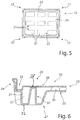
- the stronger plastic film is used for the first molded part 27, which forms the underside of the pallet base 12, on which in the corner region 17 feet 21 and intermediate feet 22 are formed. These feet 21, 22 are achieved by the deep drawing of the first plastic film, which is provided as a flat plate. This results in the first molded part 27 formed by the feet 21, 22 recesses 31, which are formed facing towards the pallet base 12 open. These areas are dashed in FIG. 5 which shows a view from above of the pallet base 12.
- the top of the transport pallet 13 is formed by the second molded part 28.
- the second molded part 28 has at least one section surface 26, which covers the recesses 31, so that the pallet base 12 is no longer interrupted by the recesses 31, but closed recesses 31 through the at least over the respective recess 31 extending support surface 26 or portions of Support surface 26 is formed. It is preferably provided that the bearing surface 26 extends from the left to the right edge of the groove 23 of the pallet base 12 along the longitudinal side and the narrow side, whereby a completely closed bearing surface 26 is formed.
- the support surface 26 can be supported in a region between the feet 21, 22 by cups or nubs 35, which are formed on the first mold part 27 and aligned in the opposite direction to the feet 21, 22.
- a stiffened pallet base 12 can be provided, this stiffened area extending between the feet 21, 22.
- This also has the advantage that a portion of the bearing surface 26, which covers the recess 31, may be formed sufficiently rigid and pressure-stable, since the directly in the adjacent and adjacent region of the recess 31 Cups or nubs 35 are formed to support the support surface 26.
- These cups or nubs 35 are preferably formed by deep drawing in the first plastic film during production of the first molded part 27. As a result, in particular the support surface 26 may be formed completely closed.
- the respective outer feet 21 are preferably elongated and preferably aligned along the longitudinal side.
- the width of the feet 21, 22 may be formed the same along the narrow side of the transport pallet 13 .
- a foot 22 is provided in the middle of the pallet base 12.
- the distances between the outer feet 21 of the longitudinal side and the intermediate foot 22 are dimensioned such that a space for forks of a forklift for gripping the transport pallet 13 is provided. This free space is preferably also provided on the narrow side of the transport pallet 13, so that with an adjustment of the forks on the forklift, the transport pallet 13 can be transported both from the longitudinal side and the narrow side.
- FIG. 6 shows a detailed embodiment of the foot 21 in a further sectional view of the transport pallet 13 according to the invention starting from the contact surface 32 of the foot 21, the first plastic film is again deformed in the direction of the second mold part 28, so that in the foot 21, a support portion 37 is formed, which extends within the recess 31.
- the support portion 37 is thus formed starting from the contact surface 32 of the foot 21, 22 by deep drawing.
- a support surface 38 extends at the upper end of the support portion 37 to the plane of the second mold part 28.
- an end-side support surface 38 of the support portion 37 abuts an underside of the second mold part 28 and is welded thereto.
- the support surface 26 is preferably supported.
- Such a support portion 37 may be provided even with narrower feet 22.
- Such support portions 37 may be formed like a dome, truncated cone, truncated pyramid or the like.
- the support portion 37 may also be formed in the form of a web.
- a web can extend over the length or width or over the diagonal of the foot, that is, the web extends between two opposite side walls or corner regions of the foot. The web extends from the footprint of the foot to the bottom of the second plastic film or the support surface on the pallet base.
- a first plastic film is heated, for example, in a separate oven (not shown) and is introduced after heating in a mold 41 ( FIG. 7 ).
- This forming tool 41 comprises an upper tool 42 and a lower tool 43.
- the lower tool 43 comprises a negative mold 44, which forms the lower outer contour of the transport pallet 13.
- There are depressions 46 for forming the feet 21, 22 and planar portions 47 are provided to form the surface portions 33, in particular with nubs 35 arranged thereon.
- the upper tool 42 comprises a flat forming surface 49, which by projections 51 (for clarity in FIG FIG. 11 shown) to form the channel 23 in the pallet base is surrounded and limited. Outside the projections 51 contours 52 are provided to form the edge 24 of the pallet base 12.
- a vacuum is applied to the lower tool 43, to effect the deep drawing operation of the first plastic film in the female mold 44.
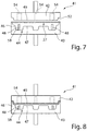
- the upper tool 42 is supplied to the lower tool 43 for closing the mold 41 ( FIG. 8 ).
- stamps 54 are provided, which engage with the stamping surface on the first plastic film during deep drawing and these feed to the formation of the first molding 27 in the direction of the lower tool 43 and in the Immerse the troughs 46 to aid in the deep drawing process by vacuum.
- the punches 54 are preferably cylindrical, so that subsequently easy removal from the mold is possible.
- the depressions 46 for forming the feet 21, 22 are conical and widen with respect to the upper tool 42.
- the mold 41 is opened, the punch 54 are returned to their original position.
- the end face of the punches 54 is in the initial position or retracted position flush with the forming surface 49 of the upper tool 42, so that a closed surface is formed to produce a flat and closed bearing surface 26 of the pallet base 12.
- a mold body 48 is provided on the lower tool 43.
- Such a shaped body 48 is shown in the figures. This shaped body 48 extends from a trough bottom 58 of the trough 56, which is provided to form a contour of the foot 21, 22. A footprint 32 of the foot 21, 22 is determined by the remaining contour of the trough bottom 58. Within the trough bottom 58, the molded body 48 extends. An outer contour of the trough bottom 58 is bounded by the lateral walls of the trough 46.
- the molded body 48 may be formed like a dome, frusto-conical or the like. Alternatively, it can also be provided that this shaped body 48 is formed as a web.
- the punch 54 arranged in the upper tool 42 is adapted to the shape and contour of the shaped body 48 on the one hand and to the contour of the hollow bottom 58 on the other hand.
- the punch 54 comprises a stamp face 55 which is of annular design.
- the punch 54 is preferably designed as a hollow cylinder. This makes it possible that during the deformation of the first plastic film, the molded body 48 can dip into the punch 54 and at the same time the punch surface 55 can be positioned to the trough bottom 58.
- the footprint surfaces 32 of the foot 21, 22 and on the other hand, the support portion 38 in the foot 21, 22 are formed and formed.
- the stamp surface is interrupted according to the width of the web. Two punch surfaces are extended adjacent to the ridge in the trough.
- the first mold part 27 remains in the lower tool, as shown in FIG. 10 is shown.
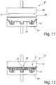
- the second plastic film is preferably introduced heated into the mold 41, as shown in FIG. 11 is shown.
- a vacuum is applied to the upper tool 42, so that the second plastic film for forming the second molded part 28 rests against the upper tool 42.
- the upper tool 42 is fed to the lower tool 43, as shown in FIG. 12 is shown, so that the first mold part 27 and second mold part 28 to form the pallet base 12 are welded together.
- the lower tool 43 can be modified such that a stamp is provided in the depression 46, which can be extended in the direction of the upper tool 42.
- the arranged in the upper tool 42 punch 54 is as a cylindrical or tubular stamp with a closed Front side formed. Consequently, upon application of the vacuum in the lower tool 43 and the subsequent extension of the punch 54 from the upper tool 42, the opposite extension of the additional punch from the lower tool 43 into the punch 54 can be controlled.
Landscapes
- Engineering & Computer Science (AREA)
- Mechanical Engineering (AREA)
- Pallets (AREA)
Claims (15)
- Palette de transport pour un récipient de transport (11) constitué de parois latérales (15, 16) qui peuvent être placées sur la palette de transport (13) et d'une partie supérieure de récipient (18), laquelle palette présente au moins une première et une deuxième pièce moulée (27, 28) qui sont formées et jointes selon le procédé de thermoformage double-paroi dit «twin-sheet», la première pièce moulée (27) formant une face inférieure de la palette de transport (13) sur laquelle sont formés des pieds (21, 22) et la deuxième pièce moulée (27, 28) formant une face supérieure de la palette de transport (13) sur laquelle est formé un fond de palette (12), ledit fond de palette (12) comprenant une surface d'appui (26) qui est délimitée par une rigole (23) s'étendant au moins partiellement dans la zone périphérique extérieure, et sur la première pièce moulée (27) étant prévu un creux (31) ouvert vers le fond de palette (12) et formé dans ladite première pièce moulée (27) par ledit au moins un pied (21, 22), caractérisée en ce que la surface d'appui (26) de la deuxième pièce moulée (28) recouvre ledit au moins un creux (31) et est formée en tant que surface d'appui (26) fermée recouvrant le creux (31) et en ce qu'au moins un pied (21, 22) de la première pièce moulée (27) présente une partie de support (37) qui s'étend depuis une surface de contact (32) du pied (21, 22) en direction de la deuxième pièce moulée (28) et soutient la surface d'appui (26) de la deuxième pièce moulée (28) laquelle recouvre le creux (31) du pied (21, 22).
- Palette de transport selon la revendication 1, caractérisée en ce qu'il est prévu respectivement une partie de support (37) par pied (21, 22), laquelle est disposée de préférence de manière centrale par rapport à la surface de contact (32) du pied (21, 22).
- Palette de transport selon la revendication 1 ou 2, caractérisée en ce qu'une surface de base de la partie de support (37) est plus petite que la moitié de la surface de contact (32) du pied (21, 22) .
- Palette de transport selon la revendication 1, caractérisée en ce que la partie de support (37) est réalisée de préférence sous forme de dôme, de cône tronqué ou de tronc de pyramide et s'étend depuis une surface de contact (32) jusque dans le creux (31).
- Palette de transport selon l'une quelconque des revendications précédentes, caractérisée en ce que la partie de support (37) présente une surface de soutien (38) qui est soudée à une face inférieure de la deuxième pièce moulée (28) et en ce que la surface de soutien (38) présente de préférence un profil tourné vers la deuxième pièce moulée (28).
- Palette de transport selon l'une quelconque des revendications précédentes, caractérisée en ce que la surface d'appui (26) est formée en tant que surface d'appui (26) fermée, exempte d'ouvertures, laquelle s'étend de préférence sur l'ensemble du fond de palette (12).
- Palette de transport selon l'une quelconque des revendications précédentes, caractérisée en ce que la surface d'appui (26) est réalisée de manière plane ou en ce que la surface d'appui (26) présente plusieurs rainures longitudinales espacées entre elles, lesquelles s'étendent de manière parallèle au côté longitudinal du fond de palette (12) et s'étendent de préférence tout le long de la surface d'appui (26).
- Palette de transport selon la revendication 1, caractérisée en ce que la première pièce moulée (27) est fabriquée à partir d'une feuille de matière plastique plus épaisse que la feuille de matière plastique utilisée pour la deuxième pièce moulée (28).
- Palette de transport selon l'une quelconque des revendications précédentes, caractérisée en ce que dans la zone d'angle (17) du fond de palette (12) est prévu respectivement un pied (21) et que l'espace libre entre les pieds (21) situés dans la zone d'angle (17) et un pied (22, 21) intermédiaire est essentiellement le même, et ce aussi bien sur le côté longitudinal que sur le côté étroit du fond de palette (12).
- Palette de transport selon l'une quelconque des revendications précédentes, caractérisée en ce que la première pièce moulée (27) présente, sur une face inférieure, des parties de surface (33) qui s'étendent entre les pieds (21, 22), dans lesdites parties de surface (33) étant formé(e)s plusieurs saillies ou tétons (35) qui s'étendent en direction de la surface d'appui (26) de la deuxième pièce moulée (28) et qui sont soudé(e)s à la face de la deuxième pièce moulée (28) située à l'opposé de ladite surface d'appui (26).
- Procédé destiné à fabriquer une palette de transport (13) selon l'une quelconque des revendications précédentes pour un récipient de transport (11) constitué de parois latérales (15, 16) qui peuvent être placées sur ladite palette de transport (13) et d'une partie supérieure de récipient (18),- lors duquel une première feuille de matière plastique, de préférence échauffée, est placée dans un outil de moulage (41), entre un outil supérieur (42) et un outil inférieur (43),- lors duquel l'outil supérieur (42) et l'outil inférieur (43) sont amenés l'un vers l'autre, puis fermés en bloquant la première feuille de matière plastique, et en ce que ladite première feuille de matière plastique est placée, par application d'un vide au niveau de l'outil inférieur (43), de manière à reposer contre un moule femelle (44) de l'outil inférieur (43), formant ainsi la première pièce moulée (27),- lors duquel pendant l'application du vide au niveau de l'outil inférieur (43), au moins un poinçon (54) sort de l'outil supérieur (42) en direction d'une cuvette (46) ménagée dans le moule femelle (44) situé dans l'outil inférieur (43), la cuvette (46) présentant un corps de moulage (48) faisant saillie en direction de l'outil supérieur (42) et le poinçon (54) présentant une surface de poinçon (55) qui, lorsque ledit poinçon (54) est sorti, entoure le corps de moulage (48) ou est contigu aux côtés latéraux dudit corps de moulage (48),- lors duquel la surface de poinçon (55) du poinçon (54) repose sur la première feuille de matière plastique et plonge dans la cuvette (46) et une surface de contact (32) du pied (21, 22) est au moins en partie formée vers le fond de la cuvette (46) et une partie de support (37) est formée entre le poinçon (54) et le corps de moulage (48),- lors duquel ledit au moins un poinçon (54) est rentré dans l'outil supérieur (42) et l'outil supérieur (42) est soulevé par rapport à l'outil inférieur (43),- lors duquel une deuxième feuille de matière plastique, de préférence échauffée, est placée entre l'outil supérieur (42) et l'outil inférieur (43),- lors duquel la deuxième feuille de matière plastique est placée, en appliquant un vide au niveau de l'outil supérieur (42) de la deuxième pièce à mouler (28), de manière à reposer contre l'outil supérieur (42) qui présente une surface de moulage (49) plane et exempte de creux destinée à former ladite au moins une surface d'appui (26) du fond de palette (12) laquelle recouvre les creux (31) des pieds (21, 22) de la première pièce moulée (27), et- lors duquel l'outil supérieur (42) et l'outil inférieur (43) sont fermés et la première et la deuxième pièce moulée (27, 28) sont assemblées l'une à l'autre par soudage et en ce que, après l'ouverture de l'outil supérieur (42) et de l'outil inférieur (43), la palette de transport (13) est sortie de l'outil de moulage (41).
- Procédé selon la revendication 11, caractérisé en ce que, lors du soudage de la première et de la deuxième pièce moulée (27, 28) au moyen de l'outil supérieur (42) et de l'outil inférieur (43), une surface de soutien (38) de la partie de support (37) est soudée à la face inférieure de la deuxième pièce moulée (28).
- Procédé selon la revendication 11 ou 12, caractérisé en ce que la feuille de matière plastique choisie pour la première pièce moulée (27) est plus épaisse que celle choisie pour la deuxième pièce moulée (28).
- Outil de moulage destiné à fabriquer une palette de transport (13) selon l'une quelconque des revendications 1 à 10 pour un récipient de transport (11) constitué de parois latérales (15, 16) qui peuvent être placées sur ladite palette de transport (13) et d'une partie supérieure de récipient (18),- avec un outil supérieur (42) et un outil inférieur (43),- avec un moule femelle (44) qui est formé dans l'outil inférieur (43) et qui comprend au moins une cuvette (46) destinée à former un pied (21, 22) de la palette de transport (13),- avec une surface de moulage (49) plane située dans l'outil supérieur (42) et tournée vers l'outil inférieur (43),- avec au moins un poinçon (54) qui est disposé dans l'outil supérieur (42) et qui peut être sorti par rapport à la surface de moulage (49) et dont la surface de poinçon (55) forme une surface plane avec la surface de moulage (49) lorsque le poinçon (54) est à l'état rentré,caractérisé en ce que- dans la cuvette (46) située dans l'outil inférieur (43) est prévu un fond de cuvette (58) en vue de former une surface de contact (32) du pied (21, 22) et en ce que dans ledit fond de cuvette (58) est prévu un corps de moulage (48) qui s'étend en direction de l'outil supérieur (42) et que la surface de poinçon (55) du poinçon (54) situé dans l'outil supérieur (42) présente un contour qui est adapté au contour du fond de cuvette (58) .
- Outil de moulage selon la revendication 14, caractérisé en ce que- le corps de moulage (48) est réalisé en forme de dôme et en ce que le poinçon (54) est réalisé en tant que cylindre creux, une partie de surface formant la surface de moulage plane (49) de l'outil supérieur (43) étant prévu au niveau de l'outil supérieur (43), et ce à l'intérieur du poinçon (54), lorsque ledit poinçon (54) est à l'état rentré, ou- le corps de moulage (48) est réalisé en forme de partie allongée et en ce que le poinçon (54) présente deux surfaces de poinçon (55) espacées l'une de l'autre selon la largeur de la partie allongée et en ce qu'entre les surfaces de poinçon (55) qui peuvent être sorties est prévue une partie de surface située dans l'outil supérieur (43) laquelle est orientée par rapport à la surface de moulage (49) de l'outil supérieur (42) de manière à former une surface plane.
Applications Claiming Priority (1)
| Application Number | Priority Date | Filing Date | Title |
|---|---|---|---|
| DE102015116056.0A DE102015116056A1 (de) | 2015-09-23 | 2015-09-23 | Transportpalette für einen Transportbehälter und Verfahren zu dessen Herstellung |
Publications (2)
| Publication Number | Publication Date |
|---|---|
| EP3147232A1 EP3147232A1 (fr) | 2017-03-29 |
| EP3147232B1 true EP3147232B1 (fr) | 2018-09-05 |
Family
ID=57103809
Family Applications (1)
| Application Number | Title | Priority Date | Filing Date |
|---|---|---|---|
| EP16190287.9A Active EP3147232B1 (fr) | 2015-09-23 | 2016-09-23 | Palette de transport pour un récipient de transport et procédé et outil de formage pour sa fabrication |
Country Status (2)
| Country | Link |
|---|---|
| EP (1) | EP3147232B1 (fr) |
| DE (1) | DE102015116056A1 (fr) |
Families Citing this family (1)
| Publication number | Priority date | Publication date | Assignee | Title |
|---|---|---|---|---|
| DE102019105062B3 (de) | 2019-02-28 | 2020-08-13 | Durotherm Kunststoffverarbeitung Gmbh | Zusammenlegbarer Ring sowie Transportbehälter mit zusammenlegbarem Ring |
Family Cites Families (11)
| Publication number | Priority date | Publication date | Assignee | Title |
|---|---|---|---|---|
| US4606278A (en) * | 1984-09-28 | 1986-08-19 | Shuert Lyle H | Twin sheet pallet |
| DE9413518U1 (de) | 1994-08-23 | 1994-10-13 | KTP Kunststofftechnik und -produktion GmbH & Co. KG, 66265 Heusweiler | Zusammenlegbarer Behälter |
| US5829595A (en) * | 1997-03-03 | 1998-11-03 | Trienda Corporation | Thin sheet thermoformed pallet sleeve |
| DE10009272A1 (de) | 2000-02-26 | 2001-09-13 | Volkswagen Ag | Zusammenlegbarer Behälter |
| US6968946B2 (en) * | 2002-12-19 | 2005-11-29 | Shuert Lyle H | Bulk container with plastic liner |
| US7343865B2 (en) * | 2006-01-17 | 2008-03-18 | Schuert Technologies Llc | Rackable twin sheet pallet |
| US20080060561A1 (en) * | 2006-09-07 | 2008-03-13 | Randy Carrasco | Modular pallet |
| DE102008058238A1 (de) * | 2008-11-19 | 2010-05-27 | Aks Kunststoff Systeme Gmbh & Co.Kg | Kunststoffpalette |
| EP2467304B1 (fr) * | 2009-08-20 | 2014-05-14 | Prime Pallets Pty Ltd | Palette de transport |
| TWM414392U (en) * | 2011-05-18 | 2011-10-21 | King & Stress Ind Co Ltd | Plastic pallet |
| DE102012219358A1 (de) * | 2012-10-19 | 2014-04-24 | Dr. Doll Holding Gmbh | Tiefgezogener Kunststoffhohlkörper und Verfahren zu seiner Herstellung |
-
2015
- 2015-09-23 DE DE102015116056.0A patent/DE102015116056A1/de not_active Withdrawn
-
2016
- 2016-09-23 EP EP16190287.9A patent/EP3147232B1/fr active Active
Also Published As
| Publication number | Publication date |
|---|---|
| EP3147232A1 (fr) | 2017-03-29 |
| DE102015116056A1 (de) | 2017-03-23 |
Similar Documents
| Publication | Publication Date | Title |
|---|---|---|
| EP2722154B1 (fr) | Corps creux en matière synthétique embouti et son procédé de fabrication | |
| DE1704282A1 (de) | Durch Blasverfahren aus Kunststoff geformte Ladeplatten | |
| DE102008012774A1 (de) | Halterungssystem zur horizontalen oder vertikalen Stapelung von gerahmten photovoltaischen oder solarthermischen Flachmodulen | |
| DE2226217A1 (de) | Spundfass aus kunststoff mit einer oder mehreren spundoeffnungen | |
| AT503830A1 (de) | Transportkasten und spritzvorrichtung für einen transportkasten | |
| EP3147232B1 (fr) | Palette de transport pour un récipient de transport et procédé et outil de formage pour sa fabrication | |
| EP0575394B1 (fr) | Disposition de bacs | |
| DE102006005873B4 (de) | Wandflächenteil und Transportbehälter | |
| EP3284689A1 (fr) | Système de paroi latérale pour un récipient, son procédé de fabrication et récipient comprenant un tel système de paroi latérale | |
| EP3750822A1 (fr) | Bague de pose pour un récipient de transport ainsi que récipient de transport | |
| DE3001787A1 (de) | Gebinde und verfahren zu seiner herstellung | |
| DE202020100361U1 (de) | Variable Transportpalette für Pflanzentöpfe | |
| DE2507275A1 (de) | Flachpalette aus kunststoff | |
| EP3543158B1 (fr) | Conteneur de transport | |
| EP3142937B1 (fr) | Récipient à parois fermées | |
| DE102019105062B3 (de) | Zusammenlegbarer Ring sowie Transportbehälter mit zusammenlegbarem Ring | |
| DE102012221843B4 (de) | Verfahren zur Aufbringung wenigstens eines Haftstreifens auf einer Unterseite eines Palettenbodens aus Kunststoff | |
| DE2337566A1 (de) | Verlade- oder stapelplatte und verfahren zu ihrer herstellung | |
| DE102009039803A1 (de) | Modularer Transportbehälter | |
| DE3503053C2 (fr) | ||
| DE102018102960B4 (de) | Aufsetzring für einen Transportbehälter, Transportbehälter sowie Verfahren zur Herstellung eines Aufsetzringes | |
| EP3048060B1 (fr) | Recipient a bord scelle et emballage | |
| EP2987742B1 (fr) | Recipient empilable ayant une structure de transfert de charge | |
| EP0645316A1 (fr) | Palette | |
| EP1805004B1 (fr) | Dispositif permettant de comprimer au moins deux couches d'un fond plie d'un emballage multicouche et emballage multicouche |
Legal Events
| Date | Code | Title | Description |
|---|---|---|---|
| PUAI | Public reference made under article 153(3) epc to a published international application that has entered the european phase |
Free format text: ORIGINAL CODE: 0009012 |
|
| STAA | Information on the status of an ep patent application or granted ep patent |
Free format text: STATUS: THE APPLICATION HAS BEEN PUBLISHED |
|
| AK | Designated contracting states |
Kind code of ref document: A1 Designated state(s): AL AT BE BG CH CY CZ DE DK EE ES FI FR GB GR HR HU IE IS IT LI LT LU LV MC MK MT NL NO PL PT RO RS SE SI SK SM TR |
|
| AX | Request for extension of the european patent |
Extension state: BA ME |
|
| STAA | Information on the status of an ep patent application or granted ep patent |
Free format text: STATUS: REQUEST FOR EXAMINATION WAS MADE |
|
| 17P | Request for examination filed |
Effective date: 20170929 |
|
| RBV | Designated contracting states (corrected) |
Designated state(s): AL AT BE BG CH CY CZ DE DK EE ES FI FR GB GR HR HU IE IS IT LI LT LU LV MC MK MT NL NO PL PT RO RS SE SI SK SM TR |
|
| GRAP | Despatch of communication of intention to grant a patent |
Free format text: ORIGINAL CODE: EPIDOSNIGR1 |
|
| STAA | Information on the status of an ep patent application or granted ep patent |
Free format text: STATUS: GRANT OF PATENT IS INTENDED |
|
| INTG | Intention to grant announced |
Effective date: 20180206 |
|
| GRAS | Grant fee paid |
Free format text: ORIGINAL CODE: EPIDOSNIGR3 |
|
| GRAA | (expected) grant |
Free format text: ORIGINAL CODE: 0009210 |
|
| STAA | Information on the status of an ep patent application or granted ep patent |
Free format text: STATUS: THE PATENT HAS BEEN GRANTED |
|
| AK | Designated contracting states |
Kind code of ref document: B1 Designated state(s): AL AT BE BG CH CY CZ DE DK EE ES FI FR GB GR HR HU IE IS IT LI LT LU LV MC MK MT NL NO PL PT RO RS SE SI SK SM TR |
|
| REG | Reference to a national code |
Ref country code: GB Ref legal event code: FG4D Free format text: NOT ENGLISH |
|
| REG | Reference to a national code |
Ref country code: CH Ref legal event code: EP |
|
| REG | Reference to a national code |
Ref country code: AT Ref legal event code: REF Ref document number: 1037521 Country of ref document: AT Kind code of ref document: T Effective date: 20180915 |
|
| REG | Reference to a national code |
Ref country code: IE Ref legal event code: FG4D Free format text: LANGUAGE OF EP DOCUMENT: GERMAN |
|
| REG | Reference to a national code |
Ref country code: DE Ref legal event code: R096 Ref document number: 502016001861 Country of ref document: DE |
|
| REG | Reference to a national code |
Ref country code: NL Ref legal event code: MP Effective date: 20180905 |
|
| REG | Reference to a national code |
Ref country code: LT Ref legal event code: MG4D |
|
| PG25 | Lapsed in a contracting state [announced via postgrant information from national office to epo] |
Ref country code: BG Free format text: LAPSE BECAUSE OF FAILURE TO SUBMIT A TRANSLATION OF THE DESCRIPTION OR TO PAY THE FEE WITHIN THE PRESCRIBED TIME-LIMIT Effective date: 20181205 Ref country code: GR Free format text: LAPSE BECAUSE OF FAILURE TO SUBMIT A TRANSLATION OF THE DESCRIPTION OR TO PAY THE FEE WITHIN THE PRESCRIBED TIME-LIMIT Effective date: 20181206 Ref country code: NO Free format text: LAPSE BECAUSE OF FAILURE TO SUBMIT A TRANSLATION OF THE DESCRIPTION OR TO PAY THE FEE WITHIN THE PRESCRIBED TIME-LIMIT Effective date: 20181205 Ref country code: RS Free format text: LAPSE BECAUSE OF FAILURE TO SUBMIT A TRANSLATION OF THE DESCRIPTION OR TO PAY THE FEE WITHIN THE PRESCRIBED TIME-LIMIT Effective date: 20180905 Ref country code: LT Free format text: LAPSE BECAUSE OF FAILURE TO SUBMIT A TRANSLATION OF THE DESCRIPTION OR TO PAY THE FEE WITHIN THE PRESCRIBED TIME-LIMIT Effective date: 20180905 Ref country code: FI Free format text: LAPSE BECAUSE OF FAILURE TO SUBMIT A TRANSLATION OF THE DESCRIPTION OR TO PAY THE FEE WITHIN THE PRESCRIBED TIME-LIMIT Effective date: 20180905 Ref country code: SE Free format text: LAPSE BECAUSE OF FAILURE TO SUBMIT A TRANSLATION OF THE DESCRIPTION OR TO PAY THE FEE WITHIN THE PRESCRIBED TIME-LIMIT Effective date: 20180905 |
|
| PG25 | Lapsed in a contracting state [announced via postgrant information from national office to epo] |
Ref country code: AL Free format text: LAPSE BECAUSE OF FAILURE TO SUBMIT A TRANSLATION OF THE DESCRIPTION OR TO PAY THE FEE WITHIN THE PRESCRIBED TIME-LIMIT Effective date: 20180905 Ref country code: HR Free format text: LAPSE BECAUSE OF FAILURE TO SUBMIT A TRANSLATION OF THE DESCRIPTION OR TO PAY THE FEE WITHIN THE PRESCRIBED TIME-LIMIT Effective date: 20180905 Ref country code: LV Free format text: LAPSE BECAUSE OF FAILURE TO SUBMIT A TRANSLATION OF THE DESCRIPTION OR TO PAY THE FEE WITHIN THE PRESCRIBED TIME-LIMIT Effective date: 20180905 |
|
| PG25 | Lapsed in a contracting state [announced via postgrant information from national office to epo] |
Ref country code: PL Free format text: LAPSE BECAUSE OF FAILURE TO SUBMIT A TRANSLATION OF THE DESCRIPTION OR TO PAY THE FEE WITHIN THE PRESCRIBED TIME-LIMIT Effective date: 20180905 Ref country code: NL Free format text: LAPSE BECAUSE OF FAILURE TO SUBMIT A TRANSLATION OF THE DESCRIPTION OR TO PAY THE FEE WITHIN THE PRESCRIBED TIME-LIMIT Effective date: 20180905 Ref country code: ES Free format text: LAPSE BECAUSE OF FAILURE TO SUBMIT A TRANSLATION OF THE DESCRIPTION OR TO PAY THE FEE WITHIN THE PRESCRIBED TIME-LIMIT Effective date: 20180905 Ref country code: IS Free format text: LAPSE BECAUSE OF FAILURE TO SUBMIT A TRANSLATION OF THE DESCRIPTION OR TO PAY THE FEE WITHIN THE PRESCRIBED TIME-LIMIT Effective date: 20190105 Ref country code: CZ Free format text: LAPSE BECAUSE OF FAILURE TO SUBMIT A TRANSLATION OF THE DESCRIPTION OR TO PAY THE FEE WITHIN THE PRESCRIBED TIME-LIMIT Effective date: 20180905 Ref country code: RO Free format text: LAPSE BECAUSE OF FAILURE TO SUBMIT A TRANSLATION OF THE DESCRIPTION OR TO PAY THE FEE WITHIN THE PRESCRIBED TIME-LIMIT Effective date: 20180905 Ref country code: IT Free format text: LAPSE BECAUSE OF FAILURE TO SUBMIT A TRANSLATION OF THE DESCRIPTION OR TO PAY THE FEE WITHIN THE PRESCRIBED TIME-LIMIT Effective date: 20180905 Ref country code: EE Free format text: LAPSE BECAUSE OF FAILURE TO SUBMIT A TRANSLATION OF THE DESCRIPTION OR TO PAY THE FEE WITHIN THE PRESCRIBED TIME-LIMIT Effective date: 20180905 |
|
| PG25 | Lapsed in a contracting state [announced via postgrant information from national office to epo] |
Ref country code: PT Free format text: LAPSE BECAUSE OF FAILURE TO SUBMIT A TRANSLATION OF THE DESCRIPTION OR TO PAY THE FEE WITHIN THE PRESCRIBED TIME-LIMIT Effective date: 20190105 Ref country code: SM Free format text: LAPSE BECAUSE OF FAILURE TO SUBMIT A TRANSLATION OF THE DESCRIPTION OR TO PAY THE FEE WITHIN THE PRESCRIBED TIME-LIMIT Effective date: 20180905 Ref country code: SK Free format text: LAPSE BECAUSE OF FAILURE TO SUBMIT A TRANSLATION OF THE DESCRIPTION OR TO PAY THE FEE WITHIN THE PRESCRIBED TIME-LIMIT Effective date: 20180905 |
|
| REG | Reference to a national code |
Ref country code: DE Ref legal event code: R097 Ref document number: 502016001861 Country of ref document: DE |
|
| REG | Reference to a national code |
Ref country code: BE Ref legal event code: MM Effective date: 20180930 |
|
| REG | Reference to a national code |
Ref country code: IE Ref legal event code: MM4A |
|
| PG25 | Lapsed in a contracting state [announced via postgrant information from national office to epo] |
Ref country code: LU Free format text: LAPSE BECAUSE OF NON-PAYMENT OF DUE FEES Effective date: 20180923 |
|
| PLBE | No opposition filed within time limit |
Free format text: ORIGINAL CODE: 0009261 |
|
| STAA | Information on the status of an ep patent application or granted ep patent |
Free format text: STATUS: NO OPPOSITION FILED WITHIN TIME LIMIT |
|
| PG25 | Lapsed in a contracting state [announced via postgrant information from national office to epo] |
Ref country code: DK Free format text: LAPSE BECAUSE OF FAILURE TO SUBMIT A TRANSLATION OF THE DESCRIPTION OR TO PAY THE FEE WITHIN THE PRESCRIBED TIME-LIMIT Effective date: 20180905 Ref country code: IE Free format text: LAPSE BECAUSE OF NON-PAYMENT OF DUE FEES Effective date: 20180923 Ref country code: MC Free format text: LAPSE BECAUSE OF FAILURE TO SUBMIT A TRANSLATION OF THE DESCRIPTION OR TO PAY THE FEE WITHIN THE PRESCRIBED TIME-LIMIT Effective date: 20180905 |
|
| 26N | No opposition filed |
Effective date: 20190606 |
|
| PG25 | Lapsed in a contracting state [announced via postgrant information from national office to epo] |
Ref country code: SI Free format text: LAPSE BECAUSE OF FAILURE TO SUBMIT A TRANSLATION OF THE DESCRIPTION OR TO PAY THE FEE WITHIN THE PRESCRIBED TIME-LIMIT Effective date: 20180905 Ref country code: BE Free format text: LAPSE BECAUSE OF NON-PAYMENT OF DUE FEES Effective date: 20180930 |
|
| PG25 | Lapsed in a contracting state [announced via postgrant information from national office to epo] |
Ref country code: FR Free format text: LAPSE BECAUSE OF NON-PAYMENT OF DUE FEES Effective date: 20181105 |
|
| PG25 | Lapsed in a contracting state [announced via postgrant information from national office to epo] |
Ref country code: MT Free format text: LAPSE BECAUSE OF FAILURE TO SUBMIT A TRANSLATION OF THE DESCRIPTION OR TO PAY THE FEE WITHIN THE PRESCRIBED TIME-LIMIT Effective date: 20180905 |
|
| PG25 | Lapsed in a contracting state [announced via postgrant information from national office to epo] |
Ref country code: TR Free format text: LAPSE BECAUSE OF FAILURE TO SUBMIT A TRANSLATION OF THE DESCRIPTION OR TO PAY THE FEE WITHIN THE PRESCRIBED TIME-LIMIT Effective date: 20180905 |
|
| REG | Reference to a national code |
Ref country code: CH Ref legal event code: PL |
|
| PG25 | Lapsed in a contracting state [announced via postgrant information from national office to epo] |
Ref country code: MK Free format text: LAPSE BECAUSE OF NON-PAYMENT OF DUE FEES Effective date: 20180905 Ref country code: CY Free format text: LAPSE BECAUSE OF FAILURE TO SUBMIT A TRANSLATION OF THE DESCRIPTION OR TO PAY THE FEE WITHIN THE PRESCRIBED TIME-LIMIT Effective date: 20180905 Ref country code: HU Free format text: LAPSE BECAUSE OF FAILURE TO SUBMIT A TRANSLATION OF THE DESCRIPTION OR TO PAY THE FEE WITHIN THE PRESCRIBED TIME-LIMIT; INVALID AB INITIO Effective date: 20160923 |
|
| REG | Reference to a national code |
Ref country code: DE Ref legal event code: R082 Ref document number: 502016001861 Country of ref document: DE Representative=s name: MAMMEL & MASER, DE Ref country code: DE Ref legal event code: R081 Ref document number: 502016001861 Country of ref document: DE Owner name: TWIN-TEC PACKAGING GMBH, DE Free format text: FORMER OWNER: VD-TECHNOLOGY B.V., ELSLOO, NL |
|
| PG25 | Lapsed in a contracting state [announced via postgrant information from national office to epo] |
Ref country code: CH Free format text: LAPSE BECAUSE OF NON-PAYMENT OF DUE FEES Effective date: 20190930 Ref country code: LI Free format text: LAPSE BECAUSE OF NON-PAYMENT OF DUE FEES Effective date: 20190930 |
|
| GBPC | Gb: european patent ceased through non-payment of renewal fee |
Effective date: 20200923 |
|
| PG25 | Lapsed in a contracting state [announced via postgrant information from national office to epo] |
Ref country code: GB Free format text: LAPSE BECAUSE OF NON-PAYMENT OF DUE FEES Effective date: 20200923 |
|
| REG | Reference to a national code |
Ref country code: AT Ref legal event code: MM01 Ref document number: 1037521 Country of ref document: AT Kind code of ref document: T Effective date: 20210923 |
|
| PG25 | Lapsed in a contracting state [announced via postgrant information from national office to epo] |
Ref country code: AT Free format text: LAPSE BECAUSE OF NON-PAYMENT OF DUE FEES Effective date: 20210923 |
|
| P01 | Opt-out of the competence of the unified patent court (upc) registered |
Effective date: 20230517 |
|
| PGFP | Annual fee paid to national office [announced via postgrant information from national office to epo] |
Ref country code: DE Payment date: 20240918 Year of fee payment: 9 |