EP3147176A1 - Système de communication sans fil, dispositif de communication sans fil, procédé de communication sans fil, système de commande de clôture mobile, dispositif de communication et dispositif de clôture mobile - Google Patents
Système de communication sans fil, dispositif de communication sans fil, procédé de communication sans fil, système de commande de clôture mobile, dispositif de communication et dispositif de clôture mobile Download PDFInfo
- Publication number
- EP3147176A1 EP3147176A1 EP14892291.7A EP14892291A EP3147176A1 EP 3147176 A1 EP3147176 A1 EP 3147176A1 EP 14892291 A EP14892291 A EP 14892291A EP 3147176 A1 EP3147176 A1 EP 3147176A1
- Authority
- EP
- European Patent Office
- Prior art keywords
- wireless communication
- communication device
- mode
- vehicle
- data
- Prior art date
- Legal status (The legal status is an assumption and is not a legal conclusion. Google has not performed a legal analysis and makes no representation as to the accuracy of the status listed.)
- Granted
Links
- 238000004891 communication Methods 0.000 title claims abstract description 500
- 238000000034 method Methods 0.000 title claims description 29
- 230000005540 biological transmission Effects 0.000 claims abstract description 163
- 230000007704 transition Effects 0.000 claims abstract description 49
- 238000005259 measurement Methods 0.000 claims description 35
- 238000013075 data extraction Methods 0.000 claims description 28
- 230000010355 oscillation Effects 0.000 claims description 21
- 239000000284 extract Substances 0.000 claims description 6
- 238000010586 diagram Methods 0.000 description 18
- 230000008569 process Effects 0.000 description 18
- 230000004044 response Effects 0.000 description 17
- 238000001514 detection method Methods 0.000 description 14
- 238000012545 processing Methods 0.000 description 9
- 238000006243 chemical reaction Methods 0.000 description 8
- 230000006870 function Effects 0.000 description 7
- 238000009434 installation Methods 0.000 description 5
- 238000005516 engineering process Methods 0.000 description 4
- 230000000694 effects Effects 0.000 description 3
- 230000002123 temporal effect Effects 0.000 description 3
- 238000013459 approach Methods 0.000 description 2
- 230000007423 decrease Effects 0.000 description 2
- 238000002360 preparation method Methods 0.000 description 2
- 230000005856 abnormality Effects 0.000 description 1
- 230000002457 bidirectional effect Effects 0.000 description 1
- 230000008859 change Effects 0.000 description 1
- 230000003247 decreasing effect Effects 0.000 description 1
- 230000005684 electric field Effects 0.000 description 1
- 230000002708 enhancing effect Effects 0.000 description 1
- 238000012986 modification Methods 0.000 description 1
- 230000004048 modification Effects 0.000 description 1
- 238000012544 monitoring process Methods 0.000 description 1
Images


Classifications
-
- B—PERFORMING OPERATIONS; TRANSPORTING
- B61—RAILWAYS
- B61L—GUIDING RAILWAY TRAFFIC; ENSURING THE SAFETY OF RAILWAY TRAFFIC
- B61L23/00—Control, warning or like safety means along the route or between vehicles or trains
- B61L23/04—Control, warning or like safety means along the route or between vehicles or trains for monitoring the mechanical state of the route
- B61L23/041—Obstacle detection
-
- B—PERFORMING OPERATIONS; TRANSPORTING
- B61—RAILWAYS
- B61L—GUIDING RAILWAY TRAFFIC; ENSURING THE SAFETY OF RAILWAY TRAFFIC
- B61L29/00—Safety means for rail/road crossing traffic
- B61L29/24—Means for warning road traffic that a gate is closed or closing, or that rail traffic is approaching, e.g. for visible or audible warning
- B61L29/28—Means for warning road traffic that a gate is closed or closing, or that rail traffic is approaching, e.g. for visible or audible warning electrically operated
- B61L29/30—Supervision, e.g. monitoring arrangements
-
- B—PERFORMING OPERATIONS; TRANSPORTING
- B61—RAILWAYS
- B61L—GUIDING RAILWAY TRAFFIC; ENSURING THE SAFETY OF RAILWAY TRAFFIC
- B61L25/00—Recording or indicating positions or identities of vehicles or trains or setting of track apparatus
- B61L25/02—Indicating or recording positions or identities of vehicles or trains
- B61L25/021—Measuring and recording of train speed
-
- B—PERFORMING OPERATIONS; TRANSPORTING
- B61—RAILWAYS
- B61L—GUIDING RAILWAY TRAFFIC; ENSURING THE SAFETY OF RAILWAY TRAFFIC
- B61L25/00—Recording or indicating positions or identities of vehicles or trains or setting of track apparatus
- B61L25/02—Indicating or recording positions or identities of vehicles or trains
- B61L25/025—Absolute localisation, e.g. providing geodetic coordinates
-
- B—PERFORMING OPERATIONS; TRANSPORTING
- B61—RAILWAYS
- B61L—GUIDING RAILWAY TRAFFIC; ENSURING THE SAFETY OF RAILWAY TRAFFIC
- B61L27/00—Central railway traffic control systems; Trackside control; Communication systems specially adapted therefor
- B61L27/40—Handling position reports or trackside vehicle data
-
- B—PERFORMING OPERATIONS; TRANSPORTING
- B61—RAILWAYS
- B61L—GUIDING RAILWAY TRAFFIC; ENSURING THE SAFETY OF RAILWAY TRAFFIC
- B61L27/00—Central railway traffic control systems; Trackside control; Communication systems specially adapted therefor
- B61L27/70—Details of trackside communication
-
- B—PERFORMING OPERATIONS; TRANSPORTING
- B61—RAILWAYS
- B61L—GUIDING RAILWAY TRAFFIC; ENSURING THE SAFETY OF RAILWAY TRAFFIC
- B61L2205/00—Communication or navigation systems for railway traffic
Definitions
- the present invention relates to a wireless technology having a mobile object stop detection function and a data communication function.
- IC tags are disposed at intervals near rails along a station platform, and an IC tag reader is mounted on the bottom or lateral surface of a train car in order to read information in the IC tags. Position information is recorded in the IC tags.
- a train entering the station platform successively determines the position of the train by allowing the IC tag reader to wirelessly read the information in the IC tags.
- the IC tag reader verifies whether the train is stopped and determines whether the train is stopped within a predetermined positional range.
- a dedicated train position determination facility is provided for the ground side to permit the train side to determine its position.
- a wireless communication device is installed on the train side and on the ground side in order to transmit data (communicate data) between the train side and the ground side.
- a surveillance camera is mounted on the station platform to monitor safety on the platform.
- a ground wireless communication device wirelessly transmits data, such as image information captured by a surveillance camera, to the train side. The captured image information is displayed on a monitor near a train driver seat. This enables a train driver to confirm the safety of passengers getting on and off the train.
- a platform monitoring system disclosed in Patent Literature 1 is configured so that a surveillance camera is installed on a platform to transmit a captured image to a train.
- a movable platform door (movable fence) is installed in recent years in order to prevent passengers from falling from a platform or coming into contact with the train.
- an image showing an area near the movable fence is captured by a surveillance camera, wirelessly transmitted to the train, and displayed on the monitor near the train driver seat. This permits the train driver to open or close the movable fence after verifying the safety of passengers getting on and off the train.
- An object of the present invention is to provide a technology that establishes wireless communication between a mobile object (e.g., a train) and a fixed object (e.g., a ground facility) in order to transmit data and determine whether the mobile object is stopped.
- a mobile object e.g., a train
- a fixed object e.g., a ground facility
- a wireless communication system has the following typical configuration.
- the wireless communication system includes a first wireless communication device and a second wireless communication device.
- the second wireless communication device wirelessly communicates with the first wireless communication device.
- One of the first and second wireless communication devices is disposed in a mobile object, and the other is fixed.
- the first wireless communication device includes a wireless transmission/reception unit that transmits data to the second wireless communication device and performs wireless transmission and reception in order to detect whether the mobile object is stopped.
- the first wireless communication device When, in a first mode for transmitting data to the second wireless communication device and determining whether the reception strength of a received signal is equal to or greater than a first value, the first wireless communication device detects that the reception strength is equal to or greater than the first value, the first wireless communication device stops the transmission of data to the second wireless communication device, exits the first mode, and transitions to a second mode for determining whether the mobile object is stopped. Upon detecting in the second mode that the mobile object is stopped, the first wireless communication device exits the second mode and transmits data to the second wireless communication device.
- a wireless communication device has the following typical configuration.
- the wireless communication device moves relative to a different wireless communication device and wirelessly communicates with the different wireless communication device.
- the wireless communication device includes a wireless transmission/reception unit that transmits data to the different wireless communication device and performs wireless transmission and reception in order to detect whether the relative movement is stopped.
- the wireless communication device detects that the reception strength is equal to or greater than the first value, the wireless communication device stops the transmission of data to the different wireless communication device, exits the first mode, and transitions to a second mode for determining whether the relative movement is stopped.
- the wireless communication device detects in the second mode that the relative movement is stopped, the wireless communication device exits the second mode and transmits data to the different wireless communication device.
- a wireless communication method according to the present invention has the following typical configuration.
- the wireless communication method is exercised between an on-vehicle wireless communication device and a ground wireless communication device.
- the on-vehicle wireless communication device is disposed in a mobile object.
- the wireless communication method includes a first step, a second step, and a third step.
- the first step determines whether the reception strength of a received signal is equal to or greater than a first value while data is being wirelessly transmitted between the on-vehicle wireless communication device and the ground wireless communication device.
- the second step stops the data transmission between the on-vehicle wireless communication device and the ground wireless communication device after detecting that the reception strength is equal to or greater than the first value, and wirelessly determines whether the mobile object is stopped.
- the third step wirelessly transmits data between the on-vehicle wireless communication device and the ground wireless communication device after detecting that the mobile object is stopped.
- a movable fence control system has the following typical configuration.
- the movable fence control system includes a first wireless communication device, a second wireless communication device, a movable fence device, and a control device.
- the first wireless communication device is disposed on a train.
- the second wireless communication device selectively operates in a data transmission mode and in a radar mode.
- the data transmission mode wirelessly communicates with the first wireless communication device.
- the radar mode wirelessly detects whether the train is stopped.
- the movable fence device is disposed on a station platform to open and close a door.
- the control device exercises control to open the door.
- the door opening instruction information is an instruction for a door opening operation.
- a communication device has the following typical configuration.
- the communication device establishes wireless communication with an on-vehicle wireless communication device disposed on a train in order to communicate with a control device that controls a door opening operation for opening a door of a movable fence device disposed on a station platform to open and close the door.
- the communication device selectively operates in a data transmission and in a radar mode.
- the data transmission mode wirelessly communicates with the on-vehicle wireless communication device.
- the radar mode wirelessly detects whether the train is stopped.
- the communication device Upon receipt of a signal requesting the door opening operation from the on-vehicle wireless communication device in the data transmission mode after detecting the stoppage of the train in the radar mode, the communication device transmits door opening instruction information to the control device.
- the door opening instruction information is an instruction for the door opening operation.
- a movable fence device has the following typical configuration.
- the movable fence device is disposed on a station platform and capable of opening and closing a door.
- the movable fence device includes a control device that communicates with a communication device.
- the communication device selectively operates in a data transmission mode and in a radar mode.
- the data transmission mode wirelessly communicates with an on-vehicle wireless communication device disposed on a train.
- the radar mode wirelessly detects whether the train is stopped.
- the control device exercises control to open the door.
- the door opening instruction information is an instruction for a door opening operation.
- the above-described configurations make it possible to transmit data and determine the stoppage of a mobile object by establishing wireless communication between a mobile object side and a fixed object side.
- Fig. 1 is a diagram illustrating a configuration of a wireless communication system according to an embodiment of the present invention.
- the reference sign 10 denotes a ground wireless communication device.
- the ground wireless communication device 10 is fixed to a position that does not obstruct the running of a vehicle 100, such as a position above the vehicle 100 or near a railway track.
- the reference sign 50 denotes a station platform (or simply a platform).
- Fig. 1 illustrates a state where the vehicle 100 is moving toward the ground wireless communication device and is about to stop at the station platform 50.
- the reference sign 20 denotes a surveillance camera that captures a situation in which the station platform 50 and the vehicle 100 are placed.
- the reference symbol 30 denotes a movable fence device disposed on the station platform 50. A door of the movable fence device 30 can be automatically opened and closed.
- the reference sign 40 denotes a control device that is capable of communicating with the ground wireless communication device 10 and used to exercise control, for example, in order to open or close the door of the movable fence device 30.
- the reference sign 110 denotes an on-vehicle wireless communication device that is disposed on the vehicle 100, which is a mobile object, and used to wirelessly communicate with the ground wireless communication device 10.
- the reference sign 120 denotes an operation/display device disposed on the vehicle 100.
- the reference sign 120a denotes a train driver.
- the control device 40 may control the surveillance camera 20 to receive and record an image captured by the surveillance camera 20.
- a device for controlling the surveillance camera 20 and receiving and recording an image captured by the surveillance camera 20 may be provided separately from the control device 40.
- the ground wireless communication device 10, the surveillance camera 20, and the movable fence device 30 are communicatively connected to the control device 40.
- the on-vehicle wireless communication device 110 is communicatively connected to the operation/display device 120.
- the ground wireless communication device 10 and the on-vehicle wireless communication device 110 are capable of wirelessly communicating with each other (performing a data transmission operation and a radar operation) through an antenna 10a of the former device 10 and an antenna 110a of the latter device 110.
- the radar operation is an operation performed to transmit an electromagnetic wave from the ground wireless communication device 10 to the vehicle 100, receive an electromagnetic wave reflected from the vehicle 100, and analyze the time lag between the transmitted and received electromagnetic waves and their frequencies in order to measure the distance between the ground wireless communication device 10 and the vehicle 100 and the movement speed of the vehicle 100 and detect whether the vehicle 100 is stopped. Details will be described later with reference to Figs. 8 (a), 8 (b) , 9 (a), and 9 (b) .
- the antenna 10a of the ground wireless communication device 10 preferably has directivity so as to be able to transmit and receive an electromagnetic wave to and from the antenna 110a of the on-vehicle wireless communication device 110, receive an electromagnetic wave reflected from the vehicle 100, and inhibit an electromagnetic wave from being received from any other direction.
- the orientation and directivity of the antenna 10a are determined in consideration, for example, of the direction of a railway track of a station where the ground wireless communication device 10 is installed.
- the antenna 10a has such directivity as to be able to transmit a beam-shaped electromagnetic wave that fits into a region having, for example, a radius of approximately 3 m at a distance of 40 m ahead.
- the antenna 10a preferably functions as a radar operation antenna and as a data transmission antenna.
- the antenna 10a may alternatively be formed of two antennas.
- the antenna 10a may be disposed separately from the ground wireless communication device 10.
- the antenna 110a of the on-vehicle wireless communication device 110 preferably has directivity so as to be able to transmit and receive an electromagnetic wave to and from the antenna 10a of the ground wireless communication device 10 and inhibit an electromagnetic wave from being received from any other direction.
- the antenna 110a may be disposed separately from the on-vehicle wireless communication device 110.
- Figs. 2 (a) and 2 (b) are diagrams outlining an operation of the wireless communication system according to the embodiment of the present invention.
- Fig. 2 (a) illustrates the positional relationship between, for example, the vehicle 100 and the station platform 50.
- the antenna 110a of the on-vehicle wireless communication device 110 is installed on the front of the vehicle 100, and the antenna 10a of the ground wireless communication device 10 is installed at such a position as not to obstruct the running of the vehicle 100.
- a reflective member e.g., a reflective plate
- the antenna 10a and the antenna 110a are positioned at a predetermined distance from each other.
- Fig. 2 (b) illustrates the reception strength of an electromagnetic wave received by the ground wireless communication device 10 (i.e., the reception strength of a signal received from the on-vehicle communication device 110).
- the reception strength may be an index reflective of a distance.
- a received signal strength indicator (RSSI) or a received electric field strength may be used as the reception strength.
- the vehicle 100 pulling in to the station platform 50 runs at a speed of 80 to 60 km/h until it reaches a position approximately 200 m from the stop sign 50a, and continues to run at a speed of 60 to 10 km/h until it reaches a position approximately 20 m from the stop sign 50a.
- the ground wireless communication device 10 continuously performs data transmission (data communication) to the on-vehicle wireless communication device 110 (first mode) until the reception strength of an electromagnetic wave transmitted from the on-vehicle wireless communication device 110 of the vehicle 100 is equal to or greater than a predetermined value (first value). That is to say, the reception strength of an electromagnetic wave transmitted from the on-vehicle wireless communication device 110 reaches the first value at a distance of approximately 20 m from the stop sign.
- the ground wireless communication device 10 transitions to the radar mode (second mode), that is, transitions from the data transmission operation to the radar operation, and functions as a distance measurement radar. That is to say, the ground wireless communication device 10 remains in the radar mode until the vehicle 100 runs at a speed of 10 to 0 km/h to the position of the stop sign 50a in order to transmit a radar electromagnetic wave toward the vehicle 100.
- the radar electromagnetic wave is repeatedly transmitted at extremely short intervals until the vehicle 100 comes to a stop. During such a period, the distance to the vehicle 100 is repeatedly measured. The distance measured until the vehicle 100 comes to a stop gradually becomes shorter. When the vehicle 100 stops, the measured distance does not change. Thus, the ground wireless communication device 10 determines the resulting state as a stopped state. In the stopped state, the ground wireless communication device 10 reverts to a data transmission mode and transmits data to the on-vehicle wireless communication device 110 (third mode).
- door opening or door closing instruction information for the movable fence device 30 which is transmitted from the vehicle 100, is wirelessly transmitted from the on-vehicle wireless communication device 110 to the ground wireless communication device 10 and then transmitted from the ground wireless communication device 10 to the control device 40. Based on the received door opening or door closing instruction information, the control device 40 opens or closes the door of the movable fence device 30.
- the resulting image information is transmitted from the surveillance camera 20 to the ground wireless communication device 10 through the control device 40 and then wirelessly transmitted from the ground wireless communication device 10 to the on-vehicle communication device 110.
- the image information received by the on-vehicle wireless communication device 110 is transmitted to the operation/display device 120 in the vehicle 100 and displayed.
- the train driver 120a checks the displayed image information to any abnormality.
- the antenna 110a of the on-vehicle wireless communication device 110 passes through the position of the antenna 10a of the ground wireless communication device 10. Then, the ground wireless communication device 10 is unable to receive an electromagnetic wave from the on-vehicle wireless communication device 110 so that the reception strength of an electromagnetic wave received by the ground wireless communication device 10 is equal to or smaller than a predetermined second value (e.g., zero). When the reception strength is equal to or smaller than the second value, the ground wireless communication device 10 reverts to the aforementioned first mode.
- a predetermined second value e.g., zero
- Fig. 3 is a communication sequence diagram of the wireless communication system according to the embodiment of the present invention.
- frequencies used by the wireless communication system are such that one transmission frequency and one reception frequency are used both by the ground wireless communication device 10 on the station side and the on-vehicle wireless communication device 110 on the vehicle side, and that an electromagnetic wave in the 60 GHz band (e.g., a 60 GHz electromagnetic wave) is used.
- an electromagnetic wave in the 60 GHz band makes it easy to perform both data transmission and distance measurement.
- An electromagnetic wave other than the electromagnetic wave in the 60 GHz band such as an electromagnetic wave in the 24 GHz band or in the 76 GHz band, may also be used.
- the initial state of the ground wireless communication device 10 is a standby state (step S1) in the first mode.
- the example depicted in Fig. 3 indicates a method that is performed by the on-vehicle wireless communication device 110 to call the ground wireless communication device 10 by using a polling call signal (step S2) and communicatively connect to the ground wireless communication device 10 that has responded by using a polling response signal (step S3).
- Figs. 4 (a) to 4 (d) illustrate communication formats of the wireless communication system according to the embodiment of the present invention.
- Fig. 4 (a) illustrates a format of the polling call signal.
- the format includes a device number, a train number, and data.
- the device number is an identifier that identifies the on-vehicle wireless communication device 110 acting as a transmitting end.
- the train number identifies the vehicle 100.
- the data includes a command (data response request) that requests the ground wireless communication device 10 to return data.
- Fig. 4 (b) illustrates a format of the polling response signal.
- the format includes a device number, a station number, a platform number, and data.
- the device number is an identifier that identifies the ground wireless communication device 10 acting as a transmission end.
- the station number is an identifier that identifies a station where the ground wireless communication device 10 is disposed.
- the platform number is an identifier that identifies a platform where the ground wireless communication device 10 is disposed.
- the data includes an ACK response to the command (data response request) of the polling call signal. The ACK response indicates that the preparation for response data transmission is ended.
- Fig. 4 (c) illustrates a format of a data transmission signal that is to be transmitted from the on-vehicle wireless communication device 110 to the ground wireless communication device 10.
- the format includes a device number, a train number, a device condition, and transmission data.
- the device number is an identifier that identifies the on-vehicle wireless communication device 110.
- the train number is an identifier that identifies the vehicle 100.
- Fig. 4 (d) illustrates a format of a data transmission signal that is to be transmitted from the ground wireless communication device 10 to the on-vehicle wireless communication device 110.
- the format includes a device number, a station number, a platform number, a device condition, and transmission data.
- the device number is an identifier that identifies the ground wireless communication device 10 acting as a transmitting end.
- the station number is an identifier that identifies a station where the ground wireless communication device 10 is disposed.
- the platform number is an identifier that identifies a platform where the ground wireless communication device 10 is disposed.
- a wireless link is established between the on-vehicle wireless communication device 110 and the ground wireless communication device 10.
- the polling call signal is transmitted repeatedly and successively in order to verify that the wireless link is established.
- the polling call signal is also transmitted during an interval between intermittent data transmissions.
- the on-vehicle wireless communication device 110 in the first mode enters the standby state where the polling call signal "CALL" (step S2) having the format illustrated in Fig. 4 (a) is transmitted repeatedly and intermittently to wait for the polling response signal "RESPONSE” (step S3) from the ground wireless communication device 10.
- the polling call signal "CALL" step S2
- the polling response signal "RESPONSE” step S3
- step S2 Upon receipt of "CALL" (step S2) from the on-vehicle wireless communication device 110, based on information included in the polling call signal, the ground wireless communication device 10 recognizes the device number of the on-vehicle wireless communication device 110, which is a communication partner, also recognizes the train number, and verifies the validity of the on-vehicle wireless communication device 110.
- the ground wireless communication device 10 exits the standby state and transmits, in the format illustrated in Fig. 4 (b) , the polling response signal "RESPONSE” (step S3) indicating that the preparation for data transmission is completed.
- the on-vehicle wireless communication device 110 Upon receipt of the polling response signal "RESPONSE", based on information included in the polling response signal, the on-vehicle wireless communication device 110 recognizes the device number of the ground wireless communication device 10, which is a communication partner, also recognizes the station number and the platform number, and verifies the validity of the ground wireless communication device 10. When the ground wireless communication device 10 is determined to be valid, the on-vehicle wireless communication device 110 transmits data in the format illustrated in Fig. 4 (c) to the ground wireless communication device 10 (step S4). The data includes a command indicative of process continuation.
- the ground wireless communication device 10 Upon receipt of data from the on-vehicle wireless communication device 110, the ground wireless communication device 10 transmits data "COMPLETE" (step S5) by using the data transmission format illustrated in Fig. 4 (d) .
- the data "COMPLETE" indicates that the step S4 data is received.
- the on-vehicle wireless communication device 110 and the ground wireless communication device 10 repeat a transmission mode communication protocol between polling transmission (step S2) and data "COMPLETE” (step S5).
- the first mode persists until the vehicle 100 reaches a position that is approximately 20 m from the stop sign 50a.
- the ground wireless communication device 10 determines whether the reception strength (reception level) is equal to or higher than the predetermined value (first value) (step S6).
- the vehicle 100 When the reception strength is equal to the first value, the vehicle 100 is positioned at a distance of approximately 20 m from the stop sign 50a. The greater the reception strength, the closer to the stop sign 50a the vehicle 100 is. The relationship between the reception strength and the position of the vehicle 100 should be measured beforehand.
- Distance measurement based on the reception strength is lower in accuracy than distance measurement in the radar mode.
- the accuracy of stoppage detection and distance measurement is increased by making distance measurements in the radar mode when the vehicle 100 is close to a stop position.
- the ground wireless communication device 10 When, in the first mode, the reception strength of the polling call signal or transmission data (step S7) from the on-vehicle wireless communication device 110 is equal to or greater than the first value (RSSI determination in step S8), that is, when the distance between the vehicle 100 and the stop sign 50a is equal to or shorter than approximately 20 m, the ground wireless communication device 10 not only transmits a mode transition request (step S9), which makes a request for transitioning to the radar mode, to the on-vehicle wireless communication device 110 by using the data transmission format illustrated in Fig. 4 (d) , but also transitions to the radar mode (second mode). That is to say, the ground wireless communication device 10 starts a distance measurement operation (radar operation) in order to measure the distance to the vehicle 100 (step S10).
- a mode transition request step S9
- radar operation a distance measurement operation
- the on-vehicle wireless communication device 110 Upon receipt of the mode transition request (strep S9), the on-vehicle wireless communication device 110 transitions to the second mode, stops the transmission of the polling call signal, and enters the standby state (step S11).
- the ground wireless communication device 10 After transitioning to the radar mode, the ground wireless communication device 10 performs the radar operation until the vehicle 100 approaches the stop sign 50a and comes to a stop. During the radar operation, the ground wireless communication device 10 repeatedly transmits an electromagnetic wave (step S12) and detects the reflection of the transmitted electromagnetic wave until the distance between the vehicle 100 and the stop sign 50a is decreased to a predetermined value (i.e., until the stoppage of the vehicle 100 is determined).
- the ground wireless communication device 10 detects that the vehicle 100 is stopped (step S13). Further, the ground wireless communication device 10 detects the stop position of the vehicle 100 by measuring the distance to the vehicle 100.
- the ground wireless communication device 10 Upon detection of the stoppage of the vehicle 100, the ground wireless communication device 10 stops its radar operation, transitions to the third mode, and transmits "STOPPAGE COMPLETE" data to the on-vehicle wireless communication device 110, which is in the standby state (step S11), by using the data transmission format illustrated in Fig. 4 (d) (step S14). That is to say, the ground wireless communication device 10 transmits a control signal that causes the on-vehicle wireless communication device 110 to revert to the data transmission mode. Subsequently, the ground wireless communication device 10, which is now placed in the third mode, enters the standby state to wait for transmission data to be transmitted from the on-vehicle wireless communication device 110 (step S15).
- the on-vehicle wireless communication device 110 Upon receipt of the "STOPPAGE COMPLETE" data, the on-vehicle wireless communication device 110 exits the standby state (step S16) and transitions to the third mode. Then, as is the case with steps S2 to S5, the on-vehicle wireless communication device 110 repeats steps S17 (polling call signal "CALL") to S20 (data transmission "COMPLETE").
- Stop position information about the vehicle 100 is transmitted from the ground wireless communication device 10 to the on-vehicle wireless communication device 110 and/or the control device 40.
- the stop position information is transmitted to the on-vehicle wireless communication device 110 when data is transmitted in step S20.
- the on-vehicle wireless communication device 110 and the control device 40 determine whether the stop position of the vehicle 100 is within a permissible range, and also determine the degree of deviation from a correct stop position. Then, in the third mode, the ground wireless communication device 10 transmits an image captured by the surveillance camera 20 to the on-vehicle wireless communication device 110.
- the ground wireless communication device 10 does not transmit the polling response signal "RESPONSE” for a continued period of time in response to the polling call signal "CALL" from the on-vehicle wireless communication device 110. If this state persists for a predetermined period of time, the on-vehicle wireless communication device 110 recognizes the end of the communication with the ground wireless communication device 10, which has been a communication partner, resets the information about the ground wireless communication device 10 (the device number of the ground wireless communication device 10, the station number, and the platform number), and transitions to the first mode. The on-vehicle wireless communication device 110 then repeatedly performs a "CALL" operation by using the polling call signal.
- ground wireless communication device 10 remains in a state where it is unable to receive the polling call signal from the on-vehicle wireless communication device 110. If this state persists for a predetermined period of time, ground wireless communication device 10 recognizes the end of the communication with the on-vehicle wireless communication device 110, which has been a communication partner, resets the information about the on-vehicle wireless communication device 110 (the device number of the on-vehicle wireless communication device 110 and the station number), and transitions to the first mode. The ground wireless communication device 10 then enters the standby state to wait for the polling call signal.
- the ground wireless communication device 10 When the vehicle 100 does not stop and passes through the station platform 50, the ground wireless communication device 10 is unable to detect the stoppage of the vehicle 100. Thus, the ground wireless communication device 10 does not transition from the second mode to the third mode. When the vehicle 100 passes through the station platform 50, the ground wireless communication device 10 is unable to detect a wave reflected from the vehicle 100. If, in the second mode, the ground wireless communication device 10 is persistently unable to detect a wave reflected from the vehicle 100 for a predetermined period of time, the ground wireless communication device 10 determines that the vehicle 100 has passed through the station platform 50, and then transitions from the second mode to the first mode.
- the on-vehicle wireless communication device 110 determines that the vehicle 100 has passed through the station platform 50, resets the information about the ground wireless communication device 10, which has been a communication partner, and transitions from the second mode to the first mode.
- Fig. 5 is a diagram illustrating a configuration of the ground wireless communication device according to the embodiment of the present invention.
- the ground wireless communication device 10 includes a control unit 11, an oscillation unit 12, a transmission unit 13, a modulation signal supply unit (modulation driver) 14, a reception unit 15, a received data extraction unit 16, a distance data extraction unit 18, and a distributor 17.
- the control unit 11 controls the ground wireless communication device 10 and processes various data.
- the oscillation unit 12 generates a carrier frequency signal.
- the transmission unit 13 transmits the carrier frequency signal and an outgoing signal.
- the modulation signal supply unit (modulation driver) 14 supplies a modulation signal based on transmission data (NRZ (Non-Return-to-Zero) signal in the present example) to the transmission unit 13.
- the reception unit 15 receives an incoming signal.
- the received data extraction unit 16 extracts received data from the incoming signal received by the reception unit 15.
- the distance data extraction unit 18 extracts distance data from the incoming signal received by the reception unit 15.
- the distributor 17 distributes the incoming signal received by the reception unit 15 to the received data extraction unit 16 and the distance data extraction unit 18.
- the oscillation unit 12 includes a PLL (Phase-Locked Loop) oscillator.
- a signal 11s2 from the control unit 11 exercises control to place the oscillation unit 12 in either the data transmission mode (first or third mode) or the radar mode (second mode).
- the oscillation unit 12 maintains the carrier frequency so that the output frequency of the oscillation unit 12 is constant. That is to say, the oscillation unit 12 generates a carrier wave signal having a constant frequency.
- the output frequency of the oscillation unit 12 is a triangular wave (having triangular time-frequency characteristics) depicted in later-described Figs. 8 (a) and 8 (b) . That is, the oscillation unit 12 generates a distance measurement signal whose frequency varies at fixed intervals.
- the control unit 11 includes an FFT processing unit 11a and a data conversion unit 11b.
- the FFT processing unit 11a calculates the distance between the on-vehicle wireless communication device 110 and the ground wireless communication device 10 on the basis of the distance data received by the reception unit 15 and extracted by the distance data extraction unit 18.
- the data conversion unit 11b converts the received data, which is received by the reception unit 15 and extracted by the received data extraction unit 16, to data transmittable to an external device.
- the FFT processing unit 11a and the data conversion unit 11b may be formed as a signal processing FPGA.
- the control unit 11 includes, as its hardware components, a CPU (Central Processing Unit) and a memory.
- the memory stores, for example, an operating program for the control unit 11.
- the CPU operates in accordance with the operating program.
- the transmission unit 13 includes a distributor 13a, a modulator 13b, a transmission amplifier 13c, and a transmission antenna 13d.
- the distributor 13a distributes an output signal from the oscillation unit 12 to the modulator 13b and to a downconverter 15c as described later.
- the modulator 13b modulates the carrier frequency signal by using the modulation signal from the modulation signal supply unit 14.
- the transmission amplifier 13c amplifies an output signal from the modulator 13b.
- the reception unit 15 includes a reception antenna 15a, a reception amplifier 15b, and the downconverter 15c.
- the reception amplifier 15b amplifies an output signal from the reception antenna 15a.
- the downconverter 15c eliminates the carrier frequency signal included in an output signal from the reception amplifier 15b.
- a wireless transmission/reception unit is configured to include the transmission unit 13 and the reception unit 15.
- the wireless transmission/reception unit transmits data to the on-vehicle wireless communication device 110, and performs wireless transmission and reception in order to detect the stoppage of the vehicle 100.
- the received data extraction unit 16 includes an IF filter 16a, an IF amplifier 16b, an envelope detector 16c, and a waveform shaper 16d.
- the IF filter 16a eliminates frequency components other than those required for received data extraction.
- the IF amplifier 16b amplifies an output signal from the IF filter 16a.
- the envelope detector 16c detects an envelope of an output signal from the IF amplifier 16b.
- the waveform shaper 16d shapes the waveform of an output signal from the envelope detector 16c.
- the distance data extraction unit 18 includes a low IF filter 18a, a low IF amplifier 18b, a low IF filter 18c, and an A/D converter (analog-to-digital converter) 18d.
- the low IF filter 18a eliminates frequency components other than those required for distance data extraction.
- the low IF amplifier 18b amplifies an output signal from the low IF filter 18a.
- the low IF filter 18c further eliminates extra frequency components.
- the A/D converter 18d digitizes an analog signal.
- the on-vehicle wireless communication device 110 does not require a distance measurement function. Therefore, the on-vehicle wireless communication device 110 may be implemented by removing the distance data extraction unit 18, the distributor 17, and the FFT processing unit 11a from the above-described configuration of the on-vehicle wireless communication device 110.
- Fig. 6 is a diagram illustrating the data transmission operation of the ground wireless communication device according to the embodiment of the present invention. First of all, a transmission operation for data transmission in the first and third modes will be described.
- the control unit 11 When the control unit 11 selects the data transmission mode (e.g., ASK modulation mode), the control unit 11 outputs a signal 11s1 and a signal 11s2 that are at the "L" level.
- the signal 11s1 transmits "L" level information to the modulation driver 14.
- the modulation driver 14 Upon receipt of the "L" level information, the modulation driver 14 supplies a modulation signal to the modulator 13b.
- the modulator 13b then uses the supplied modulation signal to modulate an inputted signal.
- the signal 11s2 transmits "L" level information to the oscillation unit 12.
- the oscillation unit 12 Upon receipt of the "L" level information, the oscillation unit 12 generates a carrier frequency signal having a constant frequency.
- the generated carrier frequency signal is inputted to the distributor 13a, and an output from the distributor 13a is distributed to two circuits.
- One of the distributed carrier frequency signals is inputted to the modulator 13b.
- An output from the modulator 13b is amplified to a predetermined value by the transmission amplifier 13c and then radiated from the transmission antenna 13d.
- the modulator 13b modulates the carrier frequency signal without attenuating its level or after attenuating its level in compliance with the NRZ signal inputted to the modulation driver 14.
- the NRZ signal is used as the transmission data.
- the above series of operations is the transmission operation for data transmission based on an ASK modulation method.
- a radio wave transmitted from the on-vehicle wireless communication device 110 is received by the reception antenna 15a, amplified to a predetermined value by the reception amplifier 15b, and inputted to the downconverter 15c.
- the radio wave is then mixed with a signal outputted from the distributor 13a (the other one of the distributed carrier frequency signals) in the downconverter 15c, and inputted to the distributor 17.
- the received signal distributed from the distributor 17 is inputted to the IF filter 16a, shaped to retain only required band components, and amplified to a predetermined level by the IF amplifier 16b.
- the received signal amplified by the IF amplifier 16b is forwarded to the envelope detector 16c and the waveform shaper 16d in order to extract data.
- the extracted data is outputted, as a signal 16ds1, to the data conversion unit 11b in the control unit 11, converted to a data transmission interface by the data conversion unit 11b, and transmitted to the external device from the ground wireless communication device 10.
- control unit 11 determines the level of a signal received by the ground wireless communication device 10, that is, the reception strength, by using a signal 16ds2 inputted from the waveform shaper 16d.
- the control unit 11 determines whether the reception strength is equal to or greater than the first value. If the reception strength is determined to be neither equal to nor greater than the first value, the control unit 11 remains in the data transmission mode (first mode) and repeatedly receives a signal and determines the reception strength. If the reception strength is determined to be equal to or greater than the first value, the control unit 11 transitions to the radar mode (second mode), and the signal 11s1 and the signal 11s2 outputted from the control unit 11 are set at the "H" level.
- the control unit 11 determines whether the reception strength is equal to or smaller than the second value. If the reception strength is determined to be neither equal to nor smaller than the second value, the control unit 11 remains in the data transmission mode (third mode), and repeatedly receives a signal and determines the reception strength. If the reception strength is determined to be equal to or smaller than the second value, the control unit 11 transitions from the third mode to the first mode.
- the operation performed in the data transmission mode (first or third mode) by the on-vehicle wireless communication device 110 is the same as the above-described operation of the ground wireless communication device 10.
- the on-vehicle wireless communication device 110 does not need to determine whether the reception strength is equal to or greater than the first value and whether the reception strength is equal to or smaller than the second value.
- Fig. 7 is a diagram illustrating the distance measurement operation of the ground wireless communication device according to the embodiment of the present invention. First of all, a transmission operation for distance measurement in the second mode will be described.
- the control unit 11 When the control unit 11 selects the radar mode, the control unit 11 outputs the signal 11s1 and the signal 11s2 that are at the "H” level.
- the signal 11s1 transmits "H" level information to the modulation driver 14.
- the modulation driver 14 Upon receipt of the "H" level information, the modulation driver 14 stops the supply of the modulation signal to the modulator 13b, which is based on the transmission data.
- the modulator 13b then allows a signal inputted from the distributor 13a to pass through as is.
- the signal 11s2 transmits "H" level information to the oscillation unit 12.
- the oscillation unit 12 Upon receipt of the "H" level information, the oscillation unit 12 generates a carrier signal whose frequency is swept at fixed intervals (see ft in Fig. 8 ).
- the generated swept frequency is inputted to the distributor 13a.
- An output from the distributor 13a is distributed to two circuits.
- One of the swept frequency signals is inputted to the modulator 13b.
- An output from the modulator 13b is amplified to a predetermined value by the transmission amplifier 13c and then radiated from the transmission antenna 13d. In such an instance, the modulator 13b allows the inputted swept frequency signal to pass through without attenuating it.
- the above series of operations is the transmission operation for measuring the distance to the vehicle 100.
- a radio wave reflected from the on-vehicle wireless communication device 110 is received by the reception antenna 15a, amplified to a predetermined value by the reception amplifier 15b, and inputted to the downconverter 15c.
- the radio wave is then mixed with a signal outputted from the distributor 13a (the other one of the distributed swept frequency signals) in the downconverter 15c, and inputted to the distributor 17.
- the received signal distributed from the distributor 17 is inputted to the low IF filter 18a, shaped to retain only required band components, and amplified to a predetermined level by the low IF amplifier 18b.
- the received signal amplified by the low IF amplifier 18b is forwarded to the low IF filter 18c in order to eliminate extra frequency components, and then digitized by the A/D converter 18d. Based on an output from the A/D converter 18d, the FFT processing unit 11a in the control unit 11 calculates the distance between the vehicle 100 and the ground wireless communication device 10.
- the control unit 11 checks the distances calculated by the FFT processing unit 11a to determine whether the difference between the last calculated distance and the currently calculated distance is zero (0), that is, whether the vehicle 100 is stopped. If it is determined that the vehicle 100 is not stopped, the control unit 11 remains in the radar mode and repeats the distance measurement operation (transmission and reception operations for distance measurement). If it is determined that the vehicle 100 is stopped, the control unit 11 transitions to the data transmission mode (third mode) so that the signal 11s1 and the signal 11s2 outputted from the control unit 11 are set at the "L" level. Further, if the control unit 11 is unable to detect a wave reflected from the vehicle 100, the control unit 11 determines that the vehicle 100 has passed through the station platform 50, and then transitions from the radar mode (second mode) to the data transmission mode (first mode).
- Figs. 8 (a) and 8 (b) are diagrams illustrating a vehicle stop state detection process and a distance measurement process that are performed in the radar mode by the ground wireless communication device 10.
- Fig. 8 (a) depicts a transmission frequency ft and a reception frequency fr.
- the transmission frequency ft is the frequency of a signal that is wirelessly transmitted from the ground wireless communication device 10 while the vehicle 100 is stopped.
- the reception frequency fr is a signal frequency that prevails when an outgoing signal having the frequency ft is reflected from the vehicle 100 and received by the ground wireless communication device 10.
- the vertical axis in Fig. 8 (a) represents frequency
- the horizontal axis represents the lapse of time.
- a difference (beat) frequency fb arises between the transmission frequency ft and the reception frequency fr.
- Fig. 8 (b) illustrates temporal changes in the difference frequency fb.
- the vertical axis in Fig. 8 (b) represents the magnitude of the difference frequency fb
- the horizontal axis represents the lapse of time.
- the difference frequency fb while the vehicle 100 is stopped, the difference frequency fb periodically decreases at an intersection point depicted in Fig. 8 (a) between the transmission frequency ft and the reception frequency fr. At the other points, however, the difference frequency fb maintains a constant magnitude. Therefore, for example, in Fig. 8 (b) , the difference frequency fb at 81 has the same magnitude as the difference frequency fb at 82. That is to say, as far as the magnitude of the difference frequency fb remains unchanged at almost all times although it periodically decreases, it can be determined that the vehicle 100 is stopped.
- the magnitude of the difference frequency fb is proportional to the time interval between the transmission of an outgoing signal having the frequency ft and the reception of an incoming signal having the frequency fr. That is, the magnitude of the difference frequency is proportional to the distance between the vehicle 100 and the ground wireless communication device 10. Therefore, the distance between the vehicle 100 and the ground wireless communication device 10 can be calculated based on the magnitude of the difference frequency.
- the relationship between the frequency difference fb and the distance from the vehicle 100 to the ground wireless communication device 10 should be determined beforehand by making measurements.
- Figs. 9 (a) and 9 (b) are diagrams illustrating a vehicle movement state detection process and a distance measurement process that are performed in the radar mode by the ground wireless communication device 10.
- Fig. 9 (a) depicts a transmission frequency ft and a reception frequency fr.
- the transmission frequency ft is the frequency of a signal that is wirelessly transmitted from the ground wireless communication device 10 while the vehicle 100 is moving.
- the reception frequency fr is a signal frequency that prevails when an outgoing signal having the frequency ft is reflected from the vehicle 100 and received by the ground wireless communication device 10.
- the vertical axis in Fig. 9 (a) represents frequency
- the horizontal axis represents the lapse of time. As illustrated in Fig. 9 (a) , there is a time lag between the transmission of an outgoing signal having the transmission frequency ft and the subsequent reception of an incoming signal having the reception frequency fr.
- a difference frequency arises between the transmission frequency ft and the reception frequency fr due to a frequency difference fb caused by the time lag and due to a frequency difference fd (Doppler shift frequency) that is caused by the Doppler effect when the vehicle 100 approaches the ground wireless communication device 10.
- Fig. 9 (b) illustrates temporal changes in the difference frequency.
- the vertical axis in Fig. 9 (b) represents the magnitude of the difference frequency
- the horizontal axis represents the lapse of time.
- the difference frequency at 91 differs in magnitude from the difference frequency at 92. That is to say, when the magnitude of the difference frequency periodically varies, it can be determined that the vehicle 100 is moving.
- the distance between the vehicle 100 and the ground wireless communication device 10 can be calculated based on the magnitude of the difference frequency. While the vehicle 100 is moving, the frequency difference fb caused by a time lag can be obtained, for example, by adding the magnitude of the difference frequency at 91 in Fig. 9 (b) to the magnitude of the difference frequency at 92 and dividing the addition result by two. Based on the obtained frequency difference fb, the distance between the vehicle 100 and the ground wireless communication device 10 can be obtained.
- the currently measured distance is different from the last measured distance, it can be determined that the vehicle 100 is moving. If, by contrast, the currently measured distance is the same as the last measured distance, it can be determined that the vehicle 100 is stopped.
- the distance between the vehicle 100 and the ground wireless communication device 10 can be calculated based on the magnitude of the difference frequency fb. Further, whether the vehicle 100 is moving or stopped can be determined based on the difference between the last measured distance and the currently measured distance or on temporal changes in the magnitude of the difference frequency fb. In the present embodiment, whether the vehicle 100 is moving or not is determined based on the distance between the last measured distance and the currently measured distance.
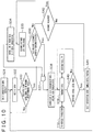
- Fig. 10 is a diagram illustrating a process performed by the ground wireless communication device according to the embodiment of the present invention. The process is controlled by the control unit 11.
- the ground wireless communication device 10 starts operating in the data transmission mode (first mode) (step S31 in Fig. 10 ).
- the control unit 11 operates the received data extraction unit 16 to perform a data conversion process.
- the control unit 11 determines whether the level of the output signal 16ds2 from the waveform shaper 16d, that is, a received signal level indicative of the reception strength, is equal to or higher than the predetermined first value (step S33).
- the data reception includes the reception of the polling call signal.
- the control unit 11 returns to step S32, and then repeatedly receives data (step S32) and checks the received signal level (step S33) until the received signal level is equal to or higher than the first value, that is, the distance between the ground wireless communication device 10 and the on-vehicle wireless communication device 110 is equal to or shorter than a predetermined value.
- the ground wireless communication device 10 transmits data to the on-vehicle wireless communication device 110 and determines whether the reception strength of a received signal is equal to or higher than the first value.
- various data are wirelessly transmitted between the on-vehicle wireless communication device 110 and the ground wireless communication device 10.
- the data received by the ground wireless communication device 10 is transmitted to the control device 40 and analyzed by the control device 40.
- step S34 If the received signal level is equal to or higher than the first value (the query in step S33 is answered "YES"), that is, if the distance between the ground wireless communication device 10 and the on-vehicle wireless communication device 110 is equal to or shorter than the predetermined value, the control unit 11 stops the data transmission and places the ground wireless communication device 10 in the radar mode (second mode) (step S34).
- the ground wireless communication device 10 when the ground wireless communication device 10 detects in the first mode that the reception strength is equal to or greater than the first value, the ground wireless communication device 10 stops the data transmission to the on-vehicle wireless communication device 110, exits the first mode, and transitions to the second mode for determining whether the vehicle 100 is stopped.
- control unit 11 operates the distance data extraction unit 18 and performs an FFT process to calculate the distance between the ground wireless communication device 10 and the on-vehicle wireless communication device 110 (step S35).
- the control unit 11 periodically repeats the distance measurement process at intervals of several microseconds to several seconds, and determines whether the currently measured distance is equal to the last measured distance (step S36).
- step S42 determines whether the current distance measurement is made (step S42). If the current distance measurement is made (the query in step S42 is answered “YES"), the control unit 11 returns to step S35 and performs the distance measurement process. If, by contrast, the current distance measurement is not made (the query in step S42 is answered “NO"), the control unit 11 determines that the vehicle 100 has passed through without coming to a stop, proceeds to later-described step S41, and resets, or more specifically, erases the device number, train number, and other relevant information about the on-vehicle wireless communication device 110, which has been a communication partner. Subsequently, the control unit 11 proceeds to step S32 of the first mode.
- step S36 determines that the vehicle 100 is stopped, and transitions from the radar mode to the data transmission mode (third mode).
- step S33 If, in this instance, the last received signal level detected during the received signal level check in step S33 is equal to or higher than the first value and the vehicle 100 is stopped (the query in step S36 is answered "YES") (step S37), the control unit 11 transitions to the data transmission mode (third mode) and resumes the data transmission (step S38). In this manner, increased safety can be provided by enhancing the accuracy with which a stopped vehicle 100 is detected.
- the ground wireless communication device 10 exits the second mode and transitions to the third mode for transmitting data to the on-vehicle wireless communication device 110.
- the ground wireless communication device 10 is able to transmit image data to the on-vehicle wireless communication device 110 (step S39), and the on-vehicle wireless communication device 110 is able to transmit information data to the ground wireless communication device 10 (step S39).
- the ground wireless communication device 10 is able to transmit information indicative of a stopped vehicle 100, information indicative of whether the stop position of the vehicle 100 is within a predetermined range, and information indicative of the stop position of the vehicle 100 to the on-vehicle wireless communication device 110 and to the control device 40.
- request information for requesting a door opening operation of the movable fence device 30 is transmitted from the operation/display device 120 to the on-vehicle wireless communication device 110 and then wirelessly transmitted from the on-vehicle wireless communication device 110 to the ground wireless communication device 10.
- the first door opening instruction information is transmitted from the ground wireless communication device 10 to the control device 40 as second door opening instruction information for giving an instruction for a door opening operation.
- the control device 40 transmits a door opening instruction control signal to the movable fence device 30.
- the movable fence device 30 operates to open its door.
- the ground wireless communication device 10 preferably transmits the second door opening instruction information to the control device 40. This prevents the door of the movable fence device 30 from opening when the vehicle is not in a normal stop position.
- video information captured by the surveillance camera 20 to indicate, for example, the condition of the station platform 50 is wirelessly transmitted from the ground wireless communication device 10 to the on-vehicle wireless communication device 110 through the control device 40.
- the video information is then transmitted from the on-vehicle wireless communication device 110 to the operation/display device 120 and displayed on the operation/display device 120.
- vehicle information about the vehicle 100 is transmitted from the on-vehicle wireless communication device 110 to the ground wireless communication device 10.
- first door closing instruction information for requesting a door closing operation of the movable fence device 30 is transmitted from the operation/display device 120 to the on-vehicle wireless communication device 110 and then wirelessly transmitted from the on-vehicle wireless communication device 110 to the ground wireless communication device 10.
- the first door closing instruction information is transmitted from the ground wireless communication device 10 to the control device 40 as second door closing instruction information for giving an instruction for a door closing operation.
- the control device 40 Upon deciphering the second door closing instruction information, transmits a door closing instruction control signal to the movable fence device 30.
- the movable fence device 30 operates to close its door.
- the control unit 11 operates the received data extraction unit 16 to perform the data conversion process in the same manner as during a period while the vehicle 100 is moving in the data transmission mode (first mode).
- the control unit 11 determines whether the received signal level is equal to or lower than the second value (whether the received signal level is zero in the example of Fig. 10 ) (step S40).
- step S40 When the vehicle 100 departs from the station platform 50 and reaches a position where communication cannot be established between the ground wireless communication device 10 and the on-vehicle wireless communication device 110, no data can be transmitted so that the received signal level is equal to or lower than the second value (e.g., zero). If the received signal level is neither equal to nor lower than the second value (the query in step S40 is answered "NO"), the control unit 11 returns to step S39, receives data, and determines whether the received signal level is equal to or lower than the second value (step S40).
- the second value e.g., zero
- step S40 If the received signal level is equal to or lower than the second value (the query in step S40 is answered "YES"), the control unit 11 resets (step S41), or more specifically, erases the device number, train number, and other relevant information about the on-vehicle wireless communication device 110, which has been a communication partner, transitions to the first mode, and enters the standby state to wait for the polling call signal.
- step S32 Upon receipt of a signal from the on-vehicle wireless communication device 110 (step S32), the control unit 11 checks whether the received signal level is equal to or higher than the first value (step S33).
- the ground wireless communication device 10 transitions to the third mode in order to transmit data to the on-vehicle wireless communication device 110 and determines whether the reception strength of a receiving signal is equal to or smaller than the second value. Upon detecting in the third mode that the reception strength is equal to or smaller than the second value, the ground wireless communication device 10 exits the third mode and transitions to the first mode.
- the on-vehicle wireless communication device 110 transitions to the first mode and turns off a monitor of the operation/display device 120. A noise screen displayed on the monitor to show the condition of the station platform 50 is then cleared. Additionally, the on-vehicle wireless communication device 110 resets, for example, the device number of the ground wireless communication device 10, which has been a communication partner, the station number, and the platform number, and then starts a new polling call.
- a predetermined value e.g., zero
- the present embodiment transitions from the radar mode to the data transmission mode (third mode) only when the vehicle 100 is stopped. Therefore, even if the train driver 120a erroneously issues an instruction for opening the door of the vehicle 100 (i.e., a door opening instruction for the movable fence device 30) while the vehicle 100 is slowly moving in the radar mode (second mode), that is, the vehicle 100 is moving, the ground wireless communication device 10 is in the radar mode and does not receive the door opening instruction for the movable fence device 30. This prevents a door opening operation from being started by an erroneous operation of the train driver 120a. As a result, increased safety is provided.
- a door opening instruction for the movable fence device 30 i.e., a door opening instruction for the movable fence device 30
- the control unit 11 of the ground wireless communication device 10 exercises control to make a mode transition from the radar mode (second mode) to the data transmission mode (third mode).
- a mode transition may alternatively be made by the train driver 120a.
- the train driver 120a uses the operation/display device 120 to issue an instruction for transitioning to the data transmission mode (third mode) after verifying that the vehicle 100 is stopped. In compliance with such an instruction, the control unit 11 transitions to the data transmission mode (third mode).
- the present embodiment provides at least the following advantageous effects.
- the ground wireless communication device checks the reception strength, transitions to the radar mode, and measures the distance to the on-vehicle wireless communication device in order to detect the stoppage of the vehicle. Upon detection of the stoppage of the vehicle, the ground wireless communication device starts a data transmission and checks the reception strength to detect whether the vehicle is moving. Alternatively, however, these operations may be performed by the on-vehicle wireless communication device.
- the on-vehicle wireless communication device transmits the polling call signal to let the ground wireless communication device respond.
- the ground wireless communication device may transmit the polling call signal to let the on-vehicle wireless communication device respond.
- the foregoing embodiment is configured so that the on-vehicle wireless communication device repeatedly transmits the polling call signal in the first mode even when the on-vehicle wireless communication device and the ground wireless communication device are at a great distance from each other.
- the first mode may be initiated when the on-vehicle wireless communication device and the ground wireless communication device are at a short distance from each other.
- an alternative is to use the radar mode when the on-vehicle wireless communication device and the ground wireless communication device are at a great distance from each other, transmit a call signal to the on-vehicle wireless communication device when the ground wireless communication device detects a train in the radar mode, and accordingly permit the on-vehicle wireless communication device and the ground wireless communication device to start a communication (particularly, a reception strength measurement by the ground wireless communication device).
- the ground wireless communication device reverts to the radar mode after exiting the third mode (after the passage of the train).
- the on-vehicle wireless communication device may transmit the call signal based on an operation of the on-vehicle wireless communication device or the operation/display device and accordingly permit the ground wireless communication device and the on-vehicle wireless communication device to start a communication (particularly, the reception strength measurement by the ground wireless communication device).
- Still another alternative is to initiate the first mode when, for example, a position sensor detects that the train has approached a station platform, let the on-vehicle wireless communication device transmit the call signal, and accordingly permit the ground wireless communication device and the on-vehicle wireless communication device to start a communication (particularly, the reception strength measurement by the ground wireless communication device).
- the foregoing embodiment has been described on the assumption that the ground wireless communication device transmits the door opening instruction information received from the on-vehicle wireless communication device to the control device when the stoppage of the vehicle is detected and the stop position of the vehicle is within the predetermined range.
- the present invention is not limited to such a configuration.
- an alternative configuration may be employed so as to inhibit the door opening operation of the vehicle unless the on-vehicle wireless communication device receives a permission signal from the ground wireless communication device.
- the permission signal is, for example, the "STOPPAGE COMPLETE" signal (S14 in Fig. 3 ).
- the on-vehicle wireless communication device Before the reception of the permission signal, the on-vehicle wireless communication device outputs a control signal for instructing the train driver to reject a vehicle door opening instruction to, for example, the operation/display device. As a result, the door of the vehicle does not open until the on-vehicle wireless communication device receives the permission signal. As far as the ground wireless communication device does not transmit the permission signal to the on-vehicle wireless communication device until the train is stopped within the predetermined range, neither the door of the vehicle nor the door of the movable fence device opens when the train erroneously stops at a position significantly apart from the stop position (stops at a position outside the predetermined range). This provides increased safety.
- the foregoing embodiment is configured so that the movable fence device is separate from the control device.
- these devices may be integrated into a single device.
- the control device may be incorporated into the movable fence device so that the control device is a part of the movable fence device.
- the foregoing embodiment has been described on the assumption that the mobile object is a train. However, it is obvious that the present invention is applicable to mobile objects other than a train.
- the present invention can be applied, for example, to a bus, automobile, a ship, an airplane, and other mobile object that stops in a predetermined area. In such an instance, the ground wireless communication device detects that the mobile object is stopped in the predetermined area.
- the present invention can be applied, for example, to a train stoppage determination technology and to a position determination technology.
Landscapes
- Engineering & Computer Science (AREA)
- Mechanical Engineering (AREA)
- Train Traffic Observation, Control, And Security (AREA)
- Mobile Radio Communication Systems (AREA)
- Platform Screen Doors And Railroad Systems (AREA)
- Radar Systems Or Details Thereof (AREA)
Applications Claiming Priority (1)
| Application Number | Priority Date | Filing Date | Title |
|---|---|---|---|
| PCT/JP2014/063362 WO2015177871A1 (fr) | 2014-05-20 | 2014-05-20 | Système de communication sans fil, dispositif de communication sans fil, procédé de communication sans fil, système de commande de clôture mobile, dispositif de communication et dispositif de clôture mobile |
Publications (3)
| Publication Number | Publication Date |
|---|---|
| EP3147176A1 true EP3147176A1 (fr) | 2017-03-29 |
| EP3147176A4 EP3147176A4 (fr) | 2018-05-23 |
| EP3147176B1 EP3147176B1 (fr) | 2022-11-30 |
Family
ID=54553568
Family Applications (1)
| Application Number | Title | Priority Date | Filing Date |
|---|---|---|---|
| EP14892291.7A Active EP3147176B1 (fr) | 2014-05-20 | 2014-05-20 | Système de communication sans fil, dispositif de communication sans fil et procédé de communication sans fil |
Country Status (5)
| Country | Link |
|---|---|
| US (1) | US10449982B2 (fr) |
| EP (1) | EP3147176B1 (fr) |
| JP (1) | JP6307600B2 (fr) |
| CN (1) | CN106458237B (fr) |
| WO (1) | WO2015177871A1 (fr) |
Cited By (1)
| Publication number | Priority date | Publication date | Assignee | Title |
|---|---|---|---|---|
| CN107933572A (zh) * | 2017-11-10 | 2018-04-20 | 成都天府轨谷科技有限公司 | 列车站场自动停靠控制系统及控制方法 |
Families Citing this family (10)
| Publication number | Priority date | Publication date | Assignee | Title |
|---|---|---|---|---|
| US10449982B2 (en) * | 2014-05-20 | 2019-10-22 | Hitachi Kokusai Electric Inc. | Wireless communication system, wireless communication device, wireless communication method, movable fence control system, communication device, and movable fence device |
| DK3078560T3 (en) * | 2015-04-07 | 2018-04-23 | Siemens Ag | System and method for interlocking a mechanical gap filler, a controlled vehicle door and a platform access door |
| WO2017018021A1 (fr) * | 2015-07-27 | 2017-02-02 | 株式会社日立国際電気 | Dispositif de mesure de distance et système de communication radio |
| US20190225246A1 (en) * | 2018-01-23 | 2019-07-25 | Arup Ventures Limited | Wireless Train Management System |
| EP3854657A4 (fr) * | 2018-09-20 | 2022-04-20 | Hitachi Kokusai Electric Inc. | Système de communication sans fil, station de base et procédé de communication sans fil |
| TWI674211B (zh) * | 2018-11-08 | 2019-10-11 | 高雄捷運股份有限公司 | 月台門系統及其控制方法 |
| CN110058239B (zh) * | 2019-04-29 | 2023-08-01 | 上海保隆汽车科技股份有限公司 | 一种车载毫米波雷达装置及目标探测方法 |
| EP3840177A1 (fr) * | 2019-12-19 | 2021-06-23 | BRUSA Elektronik AG | Appareil de détection d'objet pour un système de charge inductif |
| WO2023188385A1 (fr) * | 2022-03-31 | 2023-10-05 | Hitachi, Ltd. | Procédé de gestion d'intégrité de rame de véhicule ferroviaire, dispositif de gestion d'intégrité de rame de véhicule ferroviaire et système de gestion d'intégrité de rame de véhicule ferroviaire |
| WO2023223430A1 (fr) * | 2022-05-17 | 2023-11-23 | 三菱電機株式会社 | Système de surveillance de véhicule, dispositif sans fil au sol, dispositif embarqué, circuit de commande, support de stockage et procédé de surveillance de véhicule |
Family Cites Families (18)
| Publication number | Priority date | Publication date | Assignee | Title |
|---|---|---|---|---|
| US4551944A (en) * | 1984-01-17 | 1985-11-12 | Westinghouse Electric Corp. | Door control apparatus |
| US5786998A (en) * | 1995-05-22 | 1998-07-28 | Automated Monitoring And Control International, Inc. | Apparatus and method for tracking reporting and recording equipment inventory on a locomotive |
| IL121120A (en) * | 1997-06-19 | 2000-12-06 | Sensotech Ltd | Door opening control apparatus |
| JP3454775B2 (ja) * | 2000-03-29 | 2003-10-06 | 三洋電機株式会社 | Cdma通信システムの移動局及びハンドオフ方法 |
| US6340139B1 (en) * | 2000-06-01 | 2002-01-22 | Labarge, Inc. | Highway grade crossing vehicle violation detector |
| JP2002264811A (ja) | 2001-03-09 | 2002-09-18 | Mitsubishi Electric Corp | プラットホーム監視システム |
| JP2004077519A (ja) * | 2002-08-09 | 2004-03-11 | Toshiba Corp | 交通機関における広告方法、広告システムおよび広告管理サーバ |
| DE102004025514A1 (de) * | 2004-04-13 | 2005-11-03 | Thyssenkrupp Transrapid Gmbh | Vorrichtung zur Steuerung einer am Fahrweg eines spurgebundenen Fahrzeugs angeordneten Bahnsteigtür |
| GB2436152B (en) * | 2006-03-17 | 2011-05-04 | Knorr Bremse Rail Systems | Platform screen doors |
| US7784406B2 (en) * | 2007-05-11 | 2010-08-31 | Chisena Michael P | Train-to-platform gap mitigator |
| US7721653B1 (en) * | 2007-11-19 | 2010-05-25 | Lamass Burgess | Combined subway wall and door assembly and associated method |
| JP5023022B2 (ja) * | 2008-08-28 | 2012-09-12 | 株式会社日立製作所 | 列車停止検知システム |
| EP2244502B1 (fr) * | 2009-04-20 | 2011-06-08 | Alcatel Lucent | Procédé de transfert |
| US8909396B2 (en) * | 2011-01-25 | 2014-12-09 | The Island Radar Company | Methods and systems for detection and notification of blocked rail crossings |
| US8596587B2 (en) * | 2011-05-09 | 2013-12-03 | Bystep, Llc | Systems and methods for redundant vehicle detection at highway-rail grade crossings |
| US8751127B2 (en) * | 2011-11-30 | 2014-06-10 | General Electric Company | Position estimation system and method |
| JP2014061796A (ja) * | 2012-09-21 | 2014-04-10 | Kobe Steel Ltd | 列車停止位置検出システム |
| US10449982B2 (en) * | 2014-05-20 | 2019-10-22 | Hitachi Kokusai Electric Inc. | Wireless communication system, wireless communication device, wireless communication method, movable fence control system, communication device, and movable fence device |
-
2014
- 2014-05-20 US US15/311,637 patent/US10449982B2/en active Active
- 2014-05-20 WO PCT/JP2014/063362 patent/WO2015177871A1/fr active Application Filing
- 2014-05-20 EP EP14892291.7A patent/EP3147176B1/fr active Active
- 2014-05-20 JP JP2016520849A patent/JP6307600B2/ja active Active
- 2014-05-20 CN CN201480078879.XA patent/CN106458237B/zh active Active
Cited By (2)
| Publication number | Priority date | Publication date | Assignee | Title |
|---|---|---|---|---|
| CN107933572A (zh) * | 2017-11-10 | 2018-04-20 | 成都天府轨谷科技有限公司 | 列车站场自动停靠控制系统及控制方法 |
| CN107933572B (zh) * | 2017-11-10 | 2020-06-26 | 成都天府轨谷科技有限公司 | 列车站场自动停靠控制系统及控制方法 |
Also Published As
| Publication number | Publication date |
|---|---|
| CN106458237A (zh) | 2017-02-22 |
| JPWO2015177871A1 (ja) | 2017-04-20 |
| WO2015177871A1 (fr) | 2015-11-26 |
| JP6307600B2 (ja) | 2018-04-04 |
| US20170080962A1 (en) | 2017-03-23 |
| CN106458237B (zh) | 2018-11-27 |
| EP3147176A4 (fr) | 2018-05-23 |
| EP3147176B1 (fr) | 2022-11-30 |
| US10449982B2 (en) | 2019-10-22 |
Similar Documents
| Publication | Publication Date | Title |
|---|---|---|
| EP3147176B1 (fr) | Système de communication sans fil, dispositif de communication sans fil et procédé de communication sans fil | |
| US8730094B2 (en) | Method for determining the distance of a vehicle from a radio beacon and radio beacon for this purpose | |
| KR101956102B1 (ko) | 레이더를 이용하여 차량의 주차를 감지하는 방법 및 장치 | |
| JP2008107281A (ja) | レーダ装置 | |
| KR100774269B1 (ko) | 플랫폼 스크린 도어의 연동제어 장치 및 그의 제어 방법 | |
| KR100634638B1 (ko) | 위치측정 및 정보 전송을 위해서 송신기로부터 궤도 차량으로 전송 신호를 전송하기 위한 장치 | |
| CN107273942B (zh) | 无线标签通信装置、无线标签通信系统、通信方法 | |
| JP3908201B2 (ja) | アクティブターゲット検出システムおよび方法 | |
| WO2017018021A1 (fr) | Dispositif de mesure de distance et système de communication radio | |
| WO2018092307A1 (fr) | Dispositif et procédé de commande de communication, système de perception du péage, et programme | |
| CA3050689C (fr) | Systeme et procede pour detecter un mouvement d'un actif mobile et pour commander des operations de l'actif sur la base de son mouvement | |
| JP4389000B2 (ja) | レーダ装置およびアクティブターゲット装置 | |
| KR100851504B1 (ko) | 열차자동제어 신호 검측 시스템 및 그의 동작 방법 | |
| JP4388936B2 (ja) | アクティブターゲット検出システムおよび方法 | |
| KR102228824B1 (ko) | 레이더 센서, 레이더 장치 및 레이더 지향점 조정 시스템 | |
| US20120139724A1 (en) | Area Identification and Area Definition by Utilizing RF Technology | |
| JP2013221893A (ja) | レーダ制御装置 | |
| US10274586B2 (en) | Vehicle detection device, vehicle gate system, and method of controlling vehicle detection device | |
| JP2014120104A (ja) | 渋滞末尾検出システム及び渋滞末尾検出方法 | |
| KR20140072617A (ko) | 주차공간 인식용 초음파 장치 및 그 제어방법 | |
| CN110626390A (zh) | 一种列车定位系统和方法 | |
| KR102535824B1 (ko) | 출입 차단기용 차량인식 시스템 | |
| JP2010215167A (ja) | 列車位置検出装置 | |
| Fujita et al. | Development of new type automatic train protection ATS-Dx with permissible speed profile using on-board database |
Legal Events
| Date | Code | Title | Description |
|---|---|---|---|
| STAA | Information on the status of an ep patent application or granted ep patent |
Free format text: STATUS: THE INTERNATIONAL PUBLICATION HAS BEEN MADE |
|
| PUAI | Public reference made under article 153(3) epc to a published international application that has entered the european phase |
Free format text: ORIGINAL CODE: 0009012 |
|
| STAA | Information on the status of an ep patent application or granted ep patent |
Free format text: STATUS: REQUEST FOR EXAMINATION WAS MADE |
|
| 17P | Request for examination filed |
Effective date: 20161213 |
|
| AK | Designated contracting states |
Kind code of ref document: A1 Designated state(s): AL AT BE BG CH CY CZ DE DK EE ES FI FR GB GR HR HU IE IS IT LI LT LU LV MC MK MT NL NO PL PT RO RS SE SI SK SM TR |
|
| AX | Request for extension of the european patent |
Extension state: BA ME |
|
| DAX | Request for extension of the european patent (deleted) | ||
| RIC1 | Information provided on ipc code assigned before grant |
Ipc: B61L 23/04 20060101AFI20171214BHEP Ipc: B61L 27/00 20060101ALI20171214BHEP Ipc: B61L 25/02 20060101ALI20171214BHEP |
|
| A4 | Supplementary search report drawn up and despatched |
Effective date: 20180420 |
|
| RIC1 | Information provided on ipc code assigned before grant |
Ipc: B61L 27/00 20060101ALI20180416BHEP Ipc: B61L 25/02 20060101ALI20180416BHEP Ipc: B61L 23/04 20060101AFI20180416BHEP |
|
| STAA | Information on the status of an ep patent application or granted ep patent |
Free format text: STATUS: EXAMINATION IS IN PROGRESS |
|
| 17Q | First examination report despatched |
Effective date: 20210331 |
|
| STAA | Information on the status of an ep patent application or granted ep patent |
Free format text: STATUS: EXAMINATION IS IN PROGRESS |
|
| REG | Reference to a national code |
Ref country code: DE Ref legal event code: R079 Ref document number: 602014085699 Country of ref document: DE Free format text: PREVIOUS MAIN CLASS: B61L0023000000 Ipc: B61L0027400000 |
|
| RIC1 | Information provided on ipc code assigned before grant |
Ipc: B61L 25/02 20060101ALI20220628BHEP Ipc: B61L 23/04 20060101ALI20220628BHEP Ipc: B61L 27/40 20220101AFI20220628BHEP |
|
| GRAP | Despatch of communication of intention to grant a patent |
Free format text: ORIGINAL CODE: EPIDOSNIGR1 |
|
| STAA | Information on the status of an ep patent application or granted ep patent |
Free format text: STATUS: GRANT OF PATENT IS INTENDED |
|
| INTG | Intention to grant announced |
Effective date: 20220811 |
|
| GRAS | Grant fee paid |
Free format text: ORIGINAL CODE: EPIDOSNIGR3 |
|
| GRAA | (expected) grant |
Free format text: ORIGINAL CODE: 0009210 |
|
| STAA | Information on the status of an ep patent application or granted ep patent |
Free format text: STATUS: THE PATENT HAS BEEN GRANTED |
|
| AK | Designated contracting states |
Kind code of ref document: B1 Designated state(s): AL AT BE BG CH CY CZ DE DK EE ES FI FR GB GR HR HU IE IS IT LI LT LU LV MC MK MT NL NO PL PT RO RS SE SI SK SM TR |
|
| REG | Reference to a national code |
Ref country code: CH Ref legal event code: EP Ref country code: GB Ref legal event code: FG4D |
|
| REG | Reference to a national code |
Ref country code: AT Ref legal event code: REF Ref document number: 1534473 Country of ref document: AT Kind code of ref document: T Effective date: 20221215 Ref country code: DE Ref legal event code: R096 Ref document number: 602014085699 Country of ref document: DE |
|
| REG | Reference to a national code |
Ref country code: IE Ref legal event code: FG4D |
|
| REG | Reference to a national code |
Ref country code: LT Ref legal event code: MG9D |
|
| REG | Reference to a national code |
Ref country code: NL Ref legal event code: MP Effective date: 20221130 |
|
| PG25 | Lapsed in a contracting state [announced via postgrant information from national office to epo] |
Ref country code: SE Free format text: LAPSE BECAUSE OF FAILURE TO SUBMIT A TRANSLATION OF THE DESCRIPTION OR TO PAY THE FEE WITHIN THE PRESCRIBED TIME-LIMIT Effective date: 20221130 Ref country code: PT Free format text: LAPSE BECAUSE OF FAILURE TO SUBMIT A TRANSLATION OF THE DESCRIPTION OR TO PAY THE FEE WITHIN THE PRESCRIBED TIME-LIMIT Effective date: 20230331 Ref country code: NO Free format text: LAPSE BECAUSE OF FAILURE TO SUBMIT A TRANSLATION OF THE DESCRIPTION OR TO PAY THE FEE WITHIN THE PRESCRIBED TIME-LIMIT Effective date: 20230228 Ref country code: LT Free format text: LAPSE BECAUSE OF FAILURE TO SUBMIT A TRANSLATION OF THE DESCRIPTION OR TO PAY THE FEE WITHIN THE PRESCRIBED TIME-LIMIT Effective date: 20221130 Ref country code: FI Free format text: LAPSE BECAUSE OF FAILURE TO SUBMIT A TRANSLATION OF THE DESCRIPTION OR TO PAY THE FEE WITHIN THE PRESCRIBED TIME-LIMIT Effective date: 20221130 Ref country code: ES Free format text: LAPSE BECAUSE OF FAILURE TO SUBMIT A TRANSLATION OF THE DESCRIPTION OR TO PAY THE FEE WITHIN THE PRESCRIBED TIME-LIMIT Effective date: 20221130 |
|
| REG | Reference to a national code |
Ref country code: AT Ref legal event code: MK05 Ref document number: 1534473 Country of ref document: AT Kind code of ref document: T Effective date: 20221130 |
|
| PG25 | Lapsed in a contracting state [announced via postgrant information from national office to epo] |
Ref country code: RS Free format text: LAPSE BECAUSE OF FAILURE TO SUBMIT A TRANSLATION OF THE DESCRIPTION OR TO PAY THE FEE WITHIN THE PRESCRIBED TIME-LIMIT Effective date: 20221130 Ref country code: PL Free format text: LAPSE BECAUSE OF FAILURE TO SUBMIT A TRANSLATION OF THE DESCRIPTION OR TO PAY THE FEE WITHIN THE PRESCRIBED TIME-LIMIT Effective date: 20221130 Ref country code: LV Free format text: LAPSE BECAUSE OF FAILURE TO SUBMIT A TRANSLATION OF THE DESCRIPTION OR TO PAY THE FEE WITHIN THE PRESCRIBED TIME-LIMIT Effective date: 20221130 Ref country code: IS Free format text: LAPSE BECAUSE OF FAILURE TO SUBMIT A TRANSLATION OF THE DESCRIPTION OR TO PAY THE FEE WITHIN THE PRESCRIBED TIME-LIMIT Effective date: 20230330 Ref country code: HR Free format text: LAPSE BECAUSE OF FAILURE TO SUBMIT A TRANSLATION OF THE DESCRIPTION OR TO PAY THE FEE WITHIN THE PRESCRIBED TIME-LIMIT Effective date: 20221130 Ref country code: GR Free format text: LAPSE BECAUSE OF FAILURE TO SUBMIT A TRANSLATION OF THE DESCRIPTION OR TO PAY THE FEE WITHIN THE PRESCRIBED TIME-LIMIT Effective date: 20230301 |
|
| PG25 | Lapsed in a contracting state [announced via postgrant information from national office to epo] |
Ref country code: NL Free format text: LAPSE BECAUSE OF FAILURE TO SUBMIT A TRANSLATION OF THE DESCRIPTION OR TO PAY THE FEE WITHIN THE PRESCRIBED TIME-LIMIT Effective date: 20221130 |
|
| PG25 | Lapsed in a contracting state [announced via postgrant information from national office to epo] |
Ref country code: SM Free format text: LAPSE BECAUSE OF FAILURE TO SUBMIT A TRANSLATION OF THE DESCRIPTION OR TO PAY THE FEE WITHIN THE PRESCRIBED TIME-LIMIT Effective date: 20221130 Ref country code: RO Free format text: LAPSE BECAUSE OF FAILURE TO SUBMIT A TRANSLATION OF THE DESCRIPTION OR TO PAY THE FEE WITHIN THE PRESCRIBED TIME-LIMIT Effective date: 20221130 Ref country code: EE Free format text: LAPSE BECAUSE OF FAILURE TO SUBMIT A TRANSLATION OF THE DESCRIPTION OR TO PAY THE FEE WITHIN THE PRESCRIBED TIME-LIMIT Effective date: 20221130 Ref country code: DK Free format text: LAPSE BECAUSE OF FAILURE TO SUBMIT A TRANSLATION OF THE DESCRIPTION OR TO PAY THE FEE WITHIN THE PRESCRIBED TIME-LIMIT Effective date: 20221130 Ref country code: CZ Free format text: LAPSE BECAUSE OF FAILURE TO SUBMIT A TRANSLATION OF THE DESCRIPTION OR TO PAY THE FEE WITHIN THE PRESCRIBED TIME-LIMIT Effective date: 20221130 Ref country code: AT Free format text: LAPSE BECAUSE OF FAILURE TO SUBMIT A TRANSLATION OF THE DESCRIPTION OR TO PAY THE FEE WITHIN THE PRESCRIBED TIME-LIMIT Effective date: 20221130 |
|
| PGFP | Annual fee paid to national office [announced via postgrant information from national office to epo] |
Ref country code: FR Payment date: 20230421 Year of fee payment: 10 Ref country code: DE Payment date: 20230418 Year of fee payment: 10 |
|
| PG25 | Lapsed in a contracting state [announced via postgrant information from national office to epo] |
Ref country code: SK Free format text: LAPSE BECAUSE OF FAILURE TO SUBMIT A TRANSLATION OF THE DESCRIPTION OR TO PAY THE FEE WITHIN THE PRESCRIBED TIME-LIMIT Effective date: 20221130 Ref country code: AL Free format text: LAPSE BECAUSE OF FAILURE TO SUBMIT A TRANSLATION OF THE DESCRIPTION OR TO PAY THE FEE WITHIN THE PRESCRIBED TIME-LIMIT Effective date: 20221130 |
|
| REG | Reference to a national code |
Ref country code: DE Ref legal event code: R097 Ref document number: 602014085699 Country of ref document: DE |
|
| PLBE | No opposition filed within time limit |
Free format text: ORIGINAL CODE: 0009261 |
|
| STAA | Information on the status of an ep patent application or granted ep patent |
Free format text: STATUS: NO OPPOSITION FILED WITHIN TIME LIMIT |
|
| PGFP | Annual fee paid to national office [announced via postgrant information from national office to epo] |
Ref country code: GB Payment date: 20230413 Year of fee payment: 10 |
|
| 26N | No opposition filed |
Effective date: 20230831 |
|
| PG25 | Lapsed in a contracting state [announced via postgrant information from national office to epo] |
Ref country code: SI Free format text: LAPSE BECAUSE OF FAILURE TO SUBMIT A TRANSLATION OF THE DESCRIPTION OR TO PAY THE FEE WITHIN THE PRESCRIBED TIME-LIMIT Effective date: 20221130 |
|
| REG | Reference to a national code |
Ref country code: CH Ref legal event code: PL |
|
| PG25 | Lapsed in a contracting state [announced via postgrant information from national office to epo] |
Ref country code: MC Free format text: LAPSE BECAUSE OF FAILURE TO SUBMIT A TRANSLATION OF THE DESCRIPTION OR TO PAY THE FEE WITHIN THE PRESCRIBED TIME-LIMIT Effective date: 20221130 |
|
| REG | Reference to a national code |
Ref country code: BE Ref legal event code: MM Effective date: 20230531 |
|
| PG25 | Lapsed in a contracting state [announced via postgrant information from national office to epo] |
Ref country code: MC Free format text: LAPSE BECAUSE OF FAILURE TO SUBMIT A TRANSLATION OF THE DESCRIPTION OR TO PAY THE FEE WITHIN THE PRESCRIBED TIME-LIMIT Effective date: 20221130 Ref country code: LU Free format text: LAPSE BECAUSE OF NON-PAYMENT OF DUE FEES Effective date: 20230520 Ref country code: LI Free format text: LAPSE BECAUSE OF NON-PAYMENT OF DUE FEES Effective date: 20230531 Ref country code: CH Free format text: LAPSE BECAUSE OF NON-PAYMENT OF DUE FEES Effective date: 20230531 |
|
| REG | Reference to a national code |
Ref country code: IE Ref legal event code: MM4A |
|
| PG25 | Lapsed in a contracting state [announced via postgrant information from national office to epo] |
Ref country code: IE Free format text: LAPSE BECAUSE OF NON-PAYMENT OF DUE FEES Effective date: 20230520 |
|
| PG25 | Lapsed in a contracting state [announced via postgrant information from national office to epo] |
Ref country code: IE Free format text: LAPSE BECAUSE OF NON-PAYMENT OF DUE FEES Effective date: 20230520 |