EP3147162B1 - Rear light of vehicle and system for controlling a vehicle accessory - Google Patents
Rear light of vehicle and system for controlling a vehicle accessory Download PDFInfo
- Publication number
- EP3147162B1 EP3147162B1 EP16190470.1A EP16190470A EP3147162B1 EP 3147162 B1 EP3147162 B1 EP 3147162B1 EP 16190470 A EP16190470 A EP 16190470A EP 3147162 B1 EP3147162 B1 EP 3147162B1
- Authority
- EP
- European Patent Office
- Prior art keywords
- vehicle
- power supply
- control unit
- output terminal
- accessory
- Prior art date
- Legal status (The legal status is an assumption and is not a legal conclusion. Google has not performed a legal analysis and makes no representation as to the accuracy of the status listed.)
- Active
Links
- 238000004891 communication Methods 0.000 claims description 35
- 239000004020 conductor Substances 0.000 claims description 31
- 230000004913 activation Effects 0.000 claims description 13
- 230000009849 deactivation Effects 0.000 claims description 9
- 238000000034 method Methods 0.000 claims description 8
- 238000005259 measurement Methods 0.000 claims description 5
- 230000000007 visual effect Effects 0.000 claims description 4
- 230000006870 function Effects 0.000 description 18
- 238000001994 activation Methods 0.000 description 10
- 230000001276 controlling effect Effects 0.000 description 4
- 230000008672 reprogramming Effects 0.000 description 4
- 230000011664 signaling Effects 0.000 description 4
- 230000009131 signaling function Effects 0.000 description 3
- 235000021183 entrée Nutrition 0.000 description 2
- 239000003550 marker Substances 0.000 description 2
- 239000000126 substance Substances 0.000 description 2
- 241001080024 Telles Species 0.000 description 1
- 230000016571 aggressive behavior Effects 0.000 description 1
- 230000005540 biological transmission Effects 0.000 description 1
- 230000008859 change Effects 0.000 description 1
- 230000008878 coupling Effects 0.000 description 1
- 238000010168 coupling process Methods 0.000 description 1
- 238000005859 coupling reaction Methods 0.000 description 1
- 238000001514 detection method Methods 0.000 description 1
- 230000010354 integration Effects 0.000 description 1
- 238000004519 manufacturing process Methods 0.000 description 1
- 239000000463 material Substances 0.000 description 1
- 239000002184 metal Substances 0.000 description 1
- 238000012544 monitoring process Methods 0.000 description 1
- 229920003023 plastic Polymers 0.000 description 1
- 239000004033 plastic Substances 0.000 description 1
- 230000008569 process Effects 0.000 description 1
- 230000001105 regulatory effect Effects 0.000 description 1
- 238000011144 upstream manufacturing Methods 0.000 description 1
Images


Classifications
-
- B—PERFORMING OPERATIONS; TRANSPORTING
- B60—VEHICLES IN GENERAL
- B60R—VEHICLES, VEHICLE FITTINGS, OR VEHICLE PARTS, NOT OTHERWISE PROVIDED FOR
- B60R16/00—Electric or fluid circuits specially adapted for vehicles and not otherwise provided for; Arrangement of elements of electric or fluid circuits specially adapted for vehicles and not otherwise provided for
- B60R16/02—Electric or fluid circuits specially adapted for vehicles and not otherwise provided for; Arrangement of elements of electric or fluid circuits specially adapted for vehicles and not otherwise provided for electric constitutive elements
- B60R16/03—Electric or fluid circuits specially adapted for vehicles and not otherwise provided for; Arrangement of elements of electric or fluid circuits specially adapted for vehicles and not otherwise provided for electric constitutive elements for supply of electrical power to vehicle subsystems or for
-
- B—PERFORMING OPERATIONS; TRANSPORTING
- B60—VEHICLES IN GENERAL
- B60P—VEHICLES ADAPTED FOR LOAD TRANSPORTATION OR TO TRANSPORT, TO CARRY, OR TO COMPRISE SPECIAL LOADS OR OBJECTS
- B60P3/00—Vehicles adapted to transport, to carry or to comprise special loads or objects
-
- B—PERFORMING OPERATIONS; TRANSPORTING
- B60—VEHICLES IN GENERAL
- B60R—VEHICLES, VEHICLE FITTINGS, OR VEHICLE PARTS, NOT OTHERWISE PROVIDED FOR
- B60R16/00—Electric or fluid circuits specially adapted for vehicles and not otherwise provided for; Arrangement of elements of electric or fluid circuits specially adapted for vehicles and not otherwise provided for
- B60R16/02—Electric or fluid circuits specially adapted for vehicles and not otherwise provided for; Arrangement of elements of electric or fluid circuits specially adapted for vehicles and not otherwise provided for electric constitutive elements
- B60R16/023—Electric or fluid circuits specially adapted for vehicles and not otherwise provided for; Arrangement of elements of electric or fluid circuits specially adapted for vehicles and not otherwise provided for electric constitutive elements for transmission of signals between vehicle parts or subsystems
- B60R16/0239—Electronic boxes
-
- B—PERFORMING OPERATIONS; TRANSPORTING
- B62—LAND VEHICLES FOR TRAVELLING OTHERWISE THAN ON RAILS
- B62D—MOTOR VEHICLES; TRAILERS
- B62D53/00—Tractor-trailer combinations; Road trains
-
- B—PERFORMING OPERATIONS; TRANSPORTING
- B60—VEHICLES IN GENERAL
- B60Q—ARRANGEMENT OF SIGNALLING OR LIGHTING DEVICES, THE MOUNTING OR SUPPORTING THEREOF OR CIRCUITS THEREFOR, FOR VEHICLES IN GENERAL
- B60Q1/00—Arrangement of optical signalling or lighting devices, the mounting or supporting thereof or circuits therefor
- B60Q1/0017—Devices integrating an element dedicated to another function
Definitions
- the present invention relates to a vehicle rear lamp, a vehicle accessory control system, and a vehicle having such a rear lamp or such a control system.
- the invention also relates to a method of controlling an accessory of a vehicle by means of such a rear light.
- Some vehicles are equipped with accessories that can be operated locally by a person acting on a control member such as a button, or that can be controlled directly from the cabin.
- a control member such as a button
- heavy vehicles such as trucks may be equipped with accessories such as a lift haft or a work light, for example.
- Locally operating the accessory can be constraining because it requires the presence of an operator at the controller, potentially during the time the accessory is active. The operator can not perform other actions during this time.
- the document US 2013/0322106 describes a vehicle light comprising a vibrating device for generating an audible alarm.
- the present invention aims to overcome the disadvantages mentioned above.
- the invention relates to a vehicle rear lamp according to claim 1.
- the rear light according to the invention is not only a light signaling device, but also performs an intermediate control function for controlling the accessory.
- a wiring harness of the vehicle is connected to the rear light on the upstream side, for example via a connector having pins each connected to a conductor of the electrical supply circuit.
- the control unit can, typically via the beam, receive a certain number of data according to which it will be able to drive the output terminal, therefore the accessory connected to this output terminal and powered by this output terminal.
- the rear light according to the invention thus makes it possible to avoid complicating the vehicle network and the wiring.
- control of the output terminal by the control unit comprises in particular the activation and / or deactivation of the power supply of the output terminal.
- control unit can be connected to the supply track of the or each output terminal.
- the control unit may further be configured to measure the voltage present at the or each output terminal. This can be useful for detecting a sensor, for example a door sensor.
- the invention also has a large number of advantages related to the use of a track for supplying the output terminal from at least one of the first drivers.
- track means a thin metal strip on the surface of the electronic card which serves as an electrical connection, as opposed to a cable connection. Indeed, the use of a track makes it possible to gain compactness and to provide protection against short circuits, by implementing corresponding protection devices.
- the control unit may further be connected to each of the first drivers as well as each of the light sources, so as to control the light sources and, in some embodiments, detect the failure of a light source.
- the or each feed track comprises a switch and the control unit is connected to said switch so as to be able to control the power supply of the output terminal.
- the tail light may further comprise a voltage measuring device at the output terminal, said voltage measuring device being connected to the control unit.
- the control unit can determine if a voltage is applied to the output terminal under consideration. As previously stated, this may be useful for detecting a sensor.
- the electronic card may comprise a converter circuit having a plurality of input nodes each connected to one of the first conductors and an output node connected to each of the light sources so as to deliver to them a common supply voltage, the track power supply connecting the output terminal to said output node of the converter circuit.
- the rear light may comprise at least two output terminals, preferably at least four output terminals, each of the output terminals being connected by a supply track dedicated to at least one of the first conductors - with the interposition of the converter circuit. in a possible embodiment.
- the cable harness may further comprise a multiplexed communication medium, such as a CAN bus or a Lin bus, connected to the additional terminal of the tail light.
- a multiplexed communication medium such as a CAN bus or a Lin bus
- the invention relates to a vehicle, in particular a heavy vehicle such as a tractor or carrier truck comprising (i) at the front, a driving part comprising a cabin and (ii) at the rear, a container intended to receive goods.
- a vehicle in particular a heavy vehicle such as a tractor or carrier truck comprising (i) at the front, a driving part comprising a cabin and (ii) at the rear, a container intended to receive goods.
- This vehicle comprises at least one rear light as described above, or a control system as previously described, and at least one accessory connected to a rear light output terminal.
- the rear light can be mounted at the rear of the container, and the management system can be located in the driving part, the beam thus extending from the driving part to the rear of the vehicle.
- the driving part and the container may be separate parts but connected mechanically and electrically (as in the case of a tractor where a semi-trailer is attached to the driving part comprising the cab and a chassis), or be part of the same set (as in the case of a carrier having a common frame for the cabin and the container).
- the accessory belongs for example to the group comprising: a lift-up hanger, a door, a lighting device such as a work light, an audible alarm, a visual alarm, a distance sensor (for example an ultrasonic sensor), a door opening sensor (for example a refrigerated container door), a lift-off limit switch sensor.
- a lighting device such as a work light, an audible alarm, a visual alarm, a distance sensor (for example an ultrasonic sensor), a door opening sensor (for example a refrigerated container door), a lift-off limit switch sensor.
- the invention relates to a method of controlling an accessory of a vehicle by means of a rear light as previously described.
- This control method comprises the activation and / or deactivation, by the control unit, of the power supply of the output terminal to which the accessory is connected, as a function of at least one data received by said unit.
- control It can be an activation, or a deactivation, or a succession of activations and deactivations, such as to flash a light source.
- an operational situation of the vehicle corresponds to a set of logical conditions on said data received by said control unit, together according to which the control unit will drive the output terminal, therefore the accessory which is connected thereto.
- control method comprises the activation of the power supply of the output terminal to which the accessory is connected for a predetermined duration and / or until the control unit receives the signal. a predetermined datum.
- the figure 1 represents a vehicle 1 which is here a truck.
- the vehicle 1 comprises, at the front, a driving part 2 provided with a chassis 3, front wheels 4 and a cab 5.
- the vehicle 1 comprises a container 6 intended to receive goods, provided with rear wheels 7.
- the truck is a carrier, that is to say that it has on one and the same frame 3 the cabin 5 and the container 6.
- tractor vehicles that is to say comprising, on the one hand, a driving part comprising the cab and a chassis, and, on the other hand, a container in the form of a semi-trailer.
- a driving part comprising the cab and a chassis
- a container in the form of a semi-trailer who is in charge of the goods and who is hitched to the driving part.
- the semitrailer is mechanically attached to the chassis of the driving part, typically in an articulated manner, and electrically connected to the driving part.
- the vehicle 1 also comprises at least one accessory 12.
- the vehicle 1 may comprise one or more of the following accessories: a lift haft 12a, a lighting device such as a work light 12b, a 12c alarm (see figure 2 ) which can be audible or visual, and which can be located in the cabin 5 to be perceived by the driver of the vehicle 1.
- the vehicle 1 may include other accessories not specifically shown in the figures.
- An electrical connection is provided between the driving part 2 and the container 6, for conveying to the different signaling members of the vehicle 1 the appropriate current signals coming from the driving part 2. These current signals can be used both for the supply, control and monitoring of the various signaling devices.
- the regulatory signaling functions on a heavy vehicle container may comprise: tail lights 10, side marker lamps 11, as well as other unrepresented components, such as: front clearance lamps, rear clearance lamps , a light source of license plate lighting, etc.
- the electrical connection between the driving part 2 and the container 6 comprises a cable bundle 17, which can be installed under the floor of the container 6, which is connected, at the front, to the driving part and, at the rear, to the different signaling functions of the vehicle 1 via any additional cables 18.
- the electrical connection between the driving part and the semi-trailer may comprise one or more outlets fixed on the rear part of the driving part, and one or more outlets fixed on the part front of the semi-trailer, these plugs being connected, for example by means of an extensible cord.
- a wiring harness which can be installed under the floor of the semi-trailer, makes it possible to connect the sockets fixed on the front part of the semi-trailer. the different vehicle signaling functions via additional cables.
- the vehicle 1 further comprises a management system 20 which makes it possible to manage in a global manner the operation of various devices of the vehicle 1.
- This management system 20, located in the driving part 2, is connected to the beam 17 (see FIG. figure 2 ).
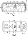
- the rear light 10 comprises a housing 21, generally of plastics material, which is fixed to the vehicle 1 by means of suitable members such as screws 22.
- the rear light 10 also comprises a window (not shown) assembled to the housing 21 .
- an electrical supply circuit of the light sources 23, comprising first conductors 26, which constitute the positive power supply, and a second conductor 27, which constitutes a ground conductor.
- Each light source 23 - or set 24 of light sources forming a particular fire function - is mounted between a first dedicated conductor 26 and the ground conductor 27.
- the beam 17 comprises first cables 28 each connected to a first conductor 26 dedicated to a light source 23 - or a set 24 of light sources - of the rear light 10.
- the beam 17 further comprises a second cable 29 constituting a ground cable
- the harness 17 may further comprise a multiplexed communication medium 25, such as a CAN bus or a Lin bus.
- the connection between the cables 28, 29 and the conductors 26, 27 can be made by means of a connector 50, which can be fixed on the housing 21 as seen on the Figures 3 and 4 .
- the connector 50 may comprise, outside the housing 21, a mechanical connection member 51 with the bundle 17, for example in the form of a threaded sleeve.
- the connector 50 further comprises pins 52 which, on the driving part 2, can be connected to the cables 28, 29 of the bundle 17 when the latter is assembled to the connector 50 and, inside the case 21 of the rear lamp 10, can be connected to the cables 26, 27.
- the rear light 10 may also comprise an additional terminal 53 ( figures 5 and 6 ) connected to the conductors 26, 27 and the cables 28, 29, which can be used for an application corresponding to another need.
- the additional terminal 53 can be arranged on a separate connector of the connector 50.
- the tail light 10 also includes at least one output terminal 55, and four output terminals in the exemplary embodiments.
- Each output terminal 55 is intended to be connected to an accessory 12 of the vehicle 1.
- an output terminal 55 may comprise pins accessible from the outside of the housing 21 through an orifice formed in a wall - for example in the bottom - of the housing 21, the orifice being surrounded or not by a chimney.
- an electronic card 31 is housed in the housing 21.
- the electronic card 31 is in the form of a plate fixed on the bottom of the housing 21 substantially parallel to it, by means of fasteners 32 such as screws.
- the electronic card 31 can occupy substantially the entire section of the housing 21.
- the electronic card 31 can serve as a support for the light sources 23 and for the conductors 26, 27, made in the form of tracks.
- each of the output terminals 55 is connected by a dedicated power supply track 35, included on the electronic card 31, to at least one of the first conductors 26.
- Each of the output terminals 55 is also connected to ground this is not shown.
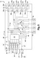
- the electronic card 31 further comprises a control unit 30 which makes it possible to manage a certain number of features of the rear light 10, as illustrated schematically and partially on the figure 3 .
- the control unit 30 is configured to control the or each output terminal 55 as a function of at least one data item received by said control unit 30.
- the solid lines are used between two elements which are connected to each other by a physical connection (whether it is a conductor in the form of a cable, or a track) allowing in particular the power supply.
- the dotted lines are used between two elements that are connected to each other, that is to say functionally associated, not necessarily by a wire connection, but by a link allowing the transmission of information or control (infrared link, microwave, etc. .).
- the electrical power supply circuit of the light sources may comprise a converter circuit 34 having a plurality of input nodes 36 each connected to one of the first conductors 26, typically via the corresponding pin 52 of the connector 50.
- the circuit converter 34 has an output node 37 connected to each of the light sources 23, so as to provide them with a common supply voltage.
- the converter circuit 34 thus makes it possible, from the different input voltages, to provide a single output voltage, which may for example correspond to the minimum value of the non-zero input voltages. This makes it possible to ensure, when it is desired to simultaneously light several light sources, that there is a sufficient supply voltage for each of these light sources to be turned on.
- the converter circuit 34 may comprise diodes.
- the output node 37 is connected to a common conductor 38 and then to each light source 23 - or 24a-24e of light sources - via a dedicated branch 39a-39e.
- each of the light sources 23 is fed by the common conductor 38, but the corresponding switch 40 is controlled by the control unit 30 which places it in the open position or in the closed position, depending on whether there is a voltage on or off. the corresponding first conductor 26, this information being received by the control unit 30 via the first connection 41.
- the control unit 30 can also be configured to measure the state of the light sources, i.e. detect the failure of a light source 23.
- a constant voltage generator 43 connecting the control unit 30 to the common conductor 38, to supply the control unit 30 with a suitable voltage, for example 5 V.
- the supply track 35 which connects an output terminal 55 to at least one of the first conductors 26, can be connected to the output node 37 of the converter circuit 34, for example by being connected to the common conductor 38 .
- Each of the supply tracks 35 may comprise a resistor 44 - allowing a measurement of the current and a protection of the corresponding output against an excessive current - and a switch 45.
- the control unit 30 is connected to each of the switches 45 via a third link 46 dedicated to each of the supply tracks 35. In this way, the control unit 30 can control each of the output terminals 55, that is to say the accessory 12 which is connected thereto, opening, closing, or successively opening and closing the switch 45.
- the switch 45 may incorporate a short-circuit protection, and open to protect the corresponding output terminal 55, based on the current measurement made by means of the resistor 44.
- the control unit 30 detects then the presence of the short-circuit via the third link 46.
- the switch 45 can also integrate a voltage measurement, to detect if a voltage is applied to the corresponding output terminal 55. This information, allowing the detection of a sensor, is transmitted to the control unit 30.
- the rear light 10 can control an accessory 12, via the control unit 30 which is able to receive data, to process them and, depending on these data, to activate and / or deactivate the power supply of the output terminal 55 to which the accessory 12 is connected.
- control unit 30 is programmed to control the output terminals 55 in a predetermined manner, on the production line, as a function of a received data item or of a set of logical conditions on several data received. .
- This programming can be frozen.
- the control unit 30 is permanently connected to the multiplexed communication medium 25, so as to be able to communicate with it and drive the accessory according to more data.
- the multiplexed communication medium 25 can provide the control unit 30 with a large amount of data from the vehicle 1, which can be sent to the management system 20 and then transferred via the multiplexed communication medium 25.
- these data can be any operating parameter of the vehicle capable of being detected or measured and transmitted by the multiplexed communication medium 25, such as speed, pressure, temperature, voltage.
- control unit 30 Several examples of control of an output terminal 55 by the control unit 30 are given below.
- Output 1 SI ((Active position function) AND (Recoil function) AND (Power supply voltage> 10V))
- the output terminal 55 concerned may be connected to a light source 12b, and be activated if the position light 24e is turned on, and if the vehicle 1 recoils or goes backward (reversing light 24c on), and provided that the battery is sufficiently charged (which corresponds to the condition relating to the minimum threshold of the supply voltage).
- Output 2 SI ((active stop function) AND (Supply voltage ⁇ 10V))
- the output concerned may be connected to a visual or audible alarm 12c to warn the driver of the situation.
- Output 3 IF ((function position Active) AND (Function RETURN TIMED 2min) AND NOT (Function Stop position))
- Output 3 IF ((Input 1) AND (NOT (Input 2)) AND (function Active)
- the outputs 1 and 2 are used as inputs and provide data according to which the output 3 will be controlled by the control unit 30.
- Output 1 SI ((vehicle speed> 50) AND (pressure ⁇ 0.5))
- Output 1 SI [(function position Active) AND ((indicator function Inactive for 1 second) or (indicator function Active))]
- the rear light 10 is no longer just a light signaling device but also a control device, and a communication node between the vehicle management system and a vehicle accessory.
Landscapes
- Engineering & Computer Science (AREA)
- Mechanical Engineering (AREA)
- Transportation (AREA)
- Chemical & Material Sciences (AREA)
- Combustion & Propulsion (AREA)
- Health & Medical Sciences (AREA)
- Public Health (AREA)
- Lighting Device Outwards From Vehicle And Optical Signal (AREA)
Description
La présente invention concerne un feu arrière de véhicule, un système de commande d'un accessoire d'un véhicule, et un véhicule comportant un tel feu arrière ou un tel système de commande. L'invention concerne également un procédé de commande d'un accessoire d'un véhicule au moyen d'un tel feu arrière.The present invention relates to a vehicle rear lamp, a vehicle accessory control system, and a vehicle having such a rear lamp or such a control system. The invention also relates to a method of controlling an accessory of a vehicle by means of such a rear light.
Certains véhicules sont équipés d'accessoires qui peuvent être actionnés localement par une personne agissant sur un organe de commande tel qu'un bouton, ou qui peuvent être commandés directement depuis la cabine. En particulier, les véhicules lourds tels que les camions peuvent être équipés d'accessoires tels qu'un haillon élévateur ou un feu de travail, par exemple.Some vehicles are equipped with accessories that can be operated locally by a person acting on a control member such as a button, or that can be controlled directly from the cabin. In particular, heavy vehicles such as trucks may be equipped with accessories such as a lift haft or a work light, for example.
L'actionnement de façon locale de l'accessoire peut s'avérer contraignant, car il nécessite la présence d'un opérateur au niveau de l'organe de commande, potentiellement pendant tout le temps où l'accessoire est actif. L'opérateur ne peut donc pas accomplir d'autres actions pendant cette durée.Locally operating the accessory can be constraining because it requires the presence of an operator at the controller, potentially during the time the accessory is active. The operator can not perform other actions during this time.
Quant à la commande de l'accessoire directement depuis la cabine, elle n'est pas toujours possible. En effet, la communication entre la cabine et l'accessoire via une liaison existante impliquerait l'utilisation d'un support de communication multiplexé, du type bus CAN ou bus Lin, qui équipe aujourd'hui un grand nombre de véhicules lourds. Mais la plupart des accessoires ne sont pas configurés pour être reliés à un tel support de communication multiplexé ni pour comprendre les données transmises par celui-ci. Ainsi, la commande de l'accessoire directement depuis la cabine nécessiterait la mise en place d'une liaison entre la cabine et l'accessoire, qui le plus souvent n'existe pas. Or, la multiplication des câbles n'est pas souhaitable pour des raisons de coût et de difficultés pratiques d'implémentation.As for the order of the accessory directly from the cabin, it is not always possible. Indeed, the communication between the cabin and the accessory via an existing link would involve the use of a multiplexed communication medium, such CAN bus or Lin bus, which nowadays equips a large number of heavy vehicles. But most accessories are not configured to be connected to such a multiplexed communication medium nor to understand the data transmitted by it. Thus, the control of the accessory directly from the cabin would require the establishment of a connection between the cabin and the accessory, which most often does not exist. However, the multiplication of cables is not desirable for reasons of cost and practical difficulties of implementation.
Le document
La présente invention vise à remédier aux inconvénients mentionnés ci-dessus.The present invention aims to overcome the disadvantages mentioned above.
A cet effet, et selon un premier aspect, l'invention concerne un feu arrière de véhicule conforme à la revendication 1.For this purpose, and according to a first aspect, the invention relates to a vehicle rear lamp according to
Ainsi, le feu arrière selon l'invention n'est pas uniquement un dispositif de signalisation lumineuse, mais remplit également une fonction d'organe de commande intermédiaire permettant la commande de l'accessoire.Thus, the rear light according to the invention is not only a light signaling device, but also performs an intermediate control function for controlling the accessory.
En pratique, un faisceau de câbles du véhicule est relié au feu arrière du côté amont, par exemple via un connecteur possédant des broches reliées chacune à un conducteur du circuit électrique d'alimentation. L'unité de commande peut, typiquement via le faisceau, recevoir un certain nombre de données en fonction desquelles elle va pouvoir piloter la borne de sortie, donc l'accessoire raccordé à cette borne de sortie et alimenté par cette borne de sortie. Le feu arrière selon l'invention permet donc d'éviter de complexifier le réseau du véhicule et le câblage.In practice, a wiring harness of the vehicle is connected to the rear light on the upstream side, for example via a connector having pins each connected to a conductor of the electrical supply circuit. The control unit can, typically via the beam, receive a certain number of data according to which it will be able to drive the output terminal, therefore the accessory connected to this output terminal and powered by this output terminal. The rear light according to the invention thus makes it possible to avoid complicating the vehicle network and the wiring.
En pratique, le pilotage de la borne de sortie par l'unité de commande comprend notamment l'activation et /ou la désactivation de l'alimentation de la borne de sortie. A cet effet, l'unité de commande peut être connectée à la piste d'alimentation de la ou de chaque borne de sortie. L'unité de commande peut en outre être configurée pour permettre la mesure de la tension présente sur la ou chaque borne de sortie. Ceci peut être utile pour détecter un capteur, par exemple un capteur de porte.In practice, the control of the output terminal by the control unit comprises in particular the activation and / or deactivation of the power supply of the output terminal. For this purpose, the control unit can be connected to the supply track of the or each output terminal. The control unit may further be configured to measure the voltage present at the or each output terminal. This can be useful for detecting a sensor, for example a door sensor.
L'invention présente de plus un grand nombre d'avantages liés à l'utilisation d'une piste pour l'alimentation de la borne de sortie depuis au moins l'un des premiers conducteurs. Par « piste », on entend une fine bande métallique à la surface de la carte électronique qui sert de liaison électrique, par opposition à une liaison par câble. En effet, l'utilisation d'une piste permet de gagner en compacité et d'assurer une protection contre les courts-circuits, par l'implémentation de dispositifs de protection correspondants.The invention also has a large number of advantages related to the use of a track for supplying the output terminal from at least one of the first drivers. By "track" means a thin metal strip on the surface of the electronic card which serves as an electrical connection, as opposed to a cable connection. Indeed, the use of a track makes it possible to gain compactness and to provide protection against short circuits, by implementing corresponding protection devices.
En outre, contrairement à une liaison par câble, une telle configuration associant unité de commande et piste :
- permet - ou du moins permet de façon considérablement facilitée - l'intégration de fonctions plus ou moins complexes telles que la présence d'un interrupteur, la mise en place d'une temporisation, le couplage de fonction selon une logique combinatoire, etc. ;
- confère au feu arrière une certaine polyvalence, par la possibilité de programmer ou reprogrammer l'unité de commande selon les besoins de l'utilisateur, tandis qu'une configuration filaire est figée ;
- offre la possibilité de piloter l'accessoire en fonction d'une donnée transmise via un support de communication multiplexé, cette donnée pouvant être traitée par l'unité de commande, et utilisée par celle-ci ou transmise à l'accessoire sous une forme acceptable par ce dernier.
- allows - or at least considerably facilitates - the integration of more or less complex functions such as the presence of a switch, the implementation of a delay, the coupling of function according to a combinatorial logic, etc. ;
- gives the taillight a certain versatility, by the possibility of programming or reprogramming the control unit according to the needs of the user, while a wired configuration is fixed;
- offers the possibility of controlling the accessory according to a data transmitted via a multiplexed communication medium, this data being able to be processed by the control unit and used by it or transmitted to the accessory in an acceptable form by the latter.
L'unité de commande peut en outre être connectée à chacun des premiers conducteurs ainsi qu'à chacune des sources lumineuses, de façon à pouvoir piloter les sources lumineuses et, dans certains modes de réalisation, détecter la défaillance d'une source lumineuse.The control unit may further be connected to each of the first drivers as well as each of the light sources, so as to control the light sources and, in some embodiments, detect the failure of a light source.
Selon une réalisation possible, la ou chaque piste d'alimentation comporte un interrupteur et l'unité de commande est connectée audit interrupteur de sorte à pouvoir piloter l'alimentation de la borne de sortie.According to one possible embodiment, the or each feed track comprises a switch and the control unit is connected to said switch so as to be able to control the power supply of the output terminal.
Le feu arrière peut en outre comprendre un dispositif de mesure de tension à la borne de sortie, ledit dispositif de mesure de tension étant connecté à l'unité de commande. Ainsi, l'unité de commande peut déterminer si une tension est appliquée sur la borne de sortie considérée. Comme indiqué précédemment, ceci peut être utile pour détecter un capteur.The tail light may further comprise a voltage measuring device at the output terminal, said voltage measuring device being connected to the control unit. Thus, the control unit can determine if a voltage is applied to the output terminal under consideration. As previously stated, this may be useful for detecting a sensor.
La carte électronique peut comprendre un circuit convertisseur ayant une pluralité de noeuds d'entrée reliés chacun à l'un des premiers conducteurs et un noeud de sortie relié à chacune des sources lumineuses de sorte à leur délivrer une tension d'alimentation commune, la piste d'alimentation reliant la borne de sortie audit noeud de sortie du circuit convertisseur.The electronic card may comprise a converter circuit having a plurality of input nodes each connected to one of the first conductors and an output node connected to each of the light sources so as to deliver to them a common supply voltage, the track power supply connecting the output terminal to said output node of the converter circuit.
Le feu arrière peut comporter au moins deux bornes de sortie, de préférence au moins quatre bornes de sortie, chacune des bornes de sortie étant reliée par une piste d'alimentation dédiée à au moins l'un des premiers conducteurs - avec interposition du circuit convertisseur selon une réalisation possible.The rear light may comprise at least two output terminals, preferably at least four output terminals, each of the output terminals being connected by a supply track dedicated to at least one of the first conductors - with the interposition of the converter circuit. in a possible embodiment.
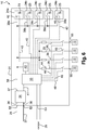
En outre, selon une réalisation possible, le feu arrière comprend une borne additionnelle reliée à l'unité de commande, ladite borne additionnelle étant configurée pour pouvoir être connectée à un support de communication multiplexé tel qu'un bus CAN ou un bus Lin, l'unité de commande étant configurée pour pouvoir communiquer avec un tel support de communication multiplexé. Avec une telle disposition, on peut prévoir :
- un fonctionnement de base du feu arrière, qui commande l'accessoire uniquement en fonction de données qui ne sont pas transmises par le support de communication multiplexé. Dans ce cas, ce support sert uniquement à la reprogrammation éventuelle de l'unité de commande, si le besoin de l'utilisateur évolue. En effet, lorsque le feu arrière est prêt à être utilisé, il n'est pas démontable, et de plus la carte électronique est noyée dans une substance permettant de la protéger des agressions, en particulier de l'humidité, la reprogrammation de l'unité de commande n'étant donc possible que si cette unité de commande a été préalablement reliée à la borne additionnelle. Ce fonctionnement de base implique donc une communication ponctuelle avec le support de communication multiplexé, ne se produisant pas souvent au cours de la durée de vie du feu arrière ;
- un fonctionnement étendu du feu arrière, offrant davantage de possibilités de commande de l'accessoire, dans la mesure où l'unité de commande peut réaliser un pilotage en fonction de données transmises via le support de communication multiplexé, celles-ci étant potentiellement nombreuses. Dans ce cas, il n'est pas nécessaire de prévoir de câblage dédié pour l'accessoire, et l'accessoire peut être piloté selon des contions logiques complexes sur la base de données qu'il ne peut pas traiter lui-même. Ce fonctionnement étendu implique donc des échanges entre l'unité de commande et le support de communication multiplexé, se produisant couramment tout au long de la durée de vie du feu arrière.
- a basic operation of the taillight, which controls the accessory only based on data that is not transmitted by the multiplexed communication medium. In this case, this support is only for reprogramming the control unit, if the need of the user evolves. Indeed, when the rear light is ready to be used, it is not removable, and moreover the electronic card is embedded in a substance to protect it from aggression, especially moisture, the reprogramming of the control unit is therefore only possible if this control unit has been previously connected to the additional terminal. This basic operation therefore involves a one-off communication with the multiplexed communication medium, not occurring often during the life of the tail lamp;
- extended operation of the taillight, offering more control possibilities of the accessory, insofar as the control unit can conduct a control based on data transmitted via the multiplexed communication medium, these being potentially numerous. In this case, it is not necessary to provide dedicated wiring for the accessory, and the accessory can be driven according to complex logical contions on the database that can not handle itself. This extended operation therefore involves exchanges between the control unit and the multiplexed communication medium, which is commonly occurring throughout the life of the tail lamp.
Selon un deuxième aspect, l'invention concerne un système de commande d'un accessoire d'un véhicule. Ce système de commande comprend :
- un système de gestion du véhicule ;
- au moins un feu arrière tel que précédemment décrit ;
- un faisceau de câbles qui relie le système de gestion du véhicule au feu arrière et qui inclut une pluralité de premiers câbles connectés chacun à un premier conducteur dédié à une source lumineuse du feu arrière, et un deuxième câble, constituant un câble de masse, connecté au deuxième conducteur.
- a vehicle management system;
- at least one rear light as previously described;
- a bundle of cables which connects the vehicle management system to the taillight and which includes a plurality of first cables each connected to a first conductor dedicated to a light source of the taillight, and a second cable, constituting a ground cable, connected to the second driver.
Le faisceau de câbles peut en outre comprendre un support de communication multiplexé, tel qu'un bus CAN ou un bus Lin, connecté à la borne additionnelle du feu arrière. Ainsi, comme exposé ci-dessus, il est possible d'envisager un fonctionnement de base du feu arrière - avec une simple reprogrammation possible de l'unité de commande - et/ou un fonctionnement étendu du feu arrière - impliquant des communications régulières entre le support de communication multiplexé et l'unité de commande.The cable harness may further comprise a multiplexed communication medium, such as a CAN bus or a Lin bus, connected to the additional terminal of the tail light. Thus, as explained above, it is possible to envisage a basic operation of the rear light - with a simple reprogramming possible from the control unit - and / or extensive operation of the taillight - involving regular communications between the multiplexed communication medium and the control unit.
Selon un troisième aspect, l'invention concerne un véhicule, en particulier véhicule lourd tel qu'un camion tracteur ou porteur comprenant (i) à l'avant, une partie motrice comportant une cabine et (ii) à l'arrière, un conteneur destiné à recevoir des marchandises. Ce véhicule comprend au moins un feu arrière tel que précédemment décrit, ou un système de commande tel que précédemment décrit, et au moins un accessoire relié à une borne de sortie du feu arrière.According to a third aspect, the invention relates to a vehicle, in particular a heavy vehicle such as a tractor or carrier truck comprising (i) at the front, a driving part comprising a cabin and (ii) at the rear, a container intended to receive goods. This vehicle comprises at least one rear light as described above, or a control system as previously described, and at least one accessory connected to a rear light output terminal.
En pratique, le feu arrière peut être monté à l'arrière du conteneur, et le système de gestion peut être situé dans la partie motrice, le faisceau s'étendant ainsi de la partie motrice jusqu'à l'arrière du véhicule.In practice, the rear light can be mounted at the rear of the container, and the management system can be located in the driving part, the beam thus extending from the driving part to the rear of the vehicle.
Il est à noter que la partie motrice et le conteneur peuvent être des pièces séparées mais connectées mécaniquement et électriquement (comme dans le cas d'un tracteur où on attèle une semi-remorque à la partie motrice comprenant la cabine et un châssis), ou faire partie d'un même ensemble (comme dans le cas d'un porteur ayant un châssis commun pour la cabine et le conteneur).It should be noted that the driving part and the container may be separate parts but connected mechanically and electrically (as in the case of a tractor where a semi-trailer is attached to the driving part comprising the cab and a chassis), or be part of the same set (as in the case of a carrier having a common frame for the cabin and the container).
L'accessoire appartient par exemple au groupe comprenant : un haillon élévateur, une porte, un dispositif d'éclairage tel qu'un feu de travail, une alarme sonore, une alarme visuelle, un capteur de distance (par exemple un capteur ultrason), un capteur d'ouverture de porte (par exemple de porte de conteneur frigorifique), un capteur de fin de course de haillon élévateur.The accessory belongs for example to the group comprising: a lift-up hanger, a door, a lighting device such as a work light, an audible alarm, a visual alarm, a distance sensor (for example an ultrasonic sensor), a door opening sensor (for example a refrigerated container door), a lift-off limit switch sensor.
Selon un quatrième aspect, l'invention concerne un procédé de commande d'un accessoire d'un véhicule au moyen d'un feu arrière tel que précédemment décrit. Ce procédé de commande comprend l'activation et/ou la désactivation, par l'unité de commande, de l'alimentation de la borne de sortie à laquelle est relié l'accessoire, en fonction d'au moins une donnée reçue par ladite unité de commande. Il peut s'agir d'une activation, ou d'une désactivation, ou d'une succession d'activations et de désactivations, de façon par exemple à faire clignoter une source lumineuse.According to a fourth aspect, the invention relates to a method of controlling an accessory of a vehicle by means of a rear light as previously described. This control method comprises the activation and / or deactivation, by the control unit, of the power supply of the output terminal to which the accessory is connected, as a function of at least one data received by said unit. control. It can be an activation, or a deactivation, or a succession of activations and deactivations, such as to flash a light source.
Ladite donnée peut appartenir au groupe comprenant :
- l'état activé ou désactivé de l'alimentation d'une des sources lumineuses du feu arrière ;
- l'état activé ou désactivé de l'alimentation de la ou de l'une des bornes de sortie, ladite borne de sortie jouant ainsi le rôle d'une borne d'entrée pour l'unité de commande ;
- la valeur d'une tension d'alimentation par rapport à un seuil prédéterminé, ceci pouvant par exemple être représentatif de la charge de la batterie du véhicule, notamment dans le but d'éviter la décharge complète de la batterie ;
- la durée d'activation ou de désactivation d'une alimentation ;
- un paramètre de fonctionnement du véhicule apte à être détecté ou mesuré et transmis par le support de communication multiplexé, tel qu'une vitesse, une pression, une température, une tension.
- the activated or deactivated state of the power supply of one of the light sources of the rear light;
- the on or off state of the power supply of the or one of the output terminals, said output terminal thereby acting as an input terminal for the control unit;
- the value of a supply voltage with respect to a predetermined threshold, this being able for example to be representative of the charge of the battery of the vehicle, in particular in order to avoid the complete discharge of the battery;
- the duration of activation or deactivation of a power supply;
- a vehicle operating parameter that can be detected or measured and transmitted by the multiplexed communication medium, such as speed, pressure, temperature, voltage.
De façon concrète, une situation opérationnelle du véhicule correspond à un ensemble de conditions logiques sur lesdites données reçues par ladite unité de commande, ensemble selon lequel l'unité de commande va piloter la borne de sortie, donc l'accessoire qui lui est relié.In concrete terms, an operational situation of the vehicle corresponds to a set of logical conditions on said data received by said control unit, together according to which the control unit will drive the output terminal, therefore the accessory which is connected thereto.
Selon une réalisation possible, le procédé de commande comprend l'activation de l'alimentation de la borne de sortie à laquelle est relié l'accessoire pendant une durée prédéterminée et/ou jusqu'à la réception, par l'unité de commande, d'une donnée prédéterminée.According to one possible embodiment, the control method comprises the activation of the power supply of the output terminal to which the accessory is connected for a predetermined duration and / or until the control unit receives the signal. a predetermined datum.
On décrit à présent, à titre d'exemples non limitatifs, plusieurs modes de réalisation possibles de l'invention, en référence aux figures annexées :
- La
figure 1 est une vue schématique en perspective, de dessous, d'un véhicule selon l'invention ; - La
figure 2 est une représentation schématique d'un véhicule comportant un accessoire et un système de commande de cet accessoire au moyen d'un feu arrière du véhicule ; - La
figure 3 est une vue schématique de l'intérieur d'un feu arrière selon l'invention ; - La
figure 4 est une vue extérieure du feu arrière de lafigure 3 ; - La
figure 5 est une représentation schématique d'un feu arrière selon un premier mode de réalisation de l'invention ; - La
figure 6 est une représentation schématique d'un feu arrière selon un deuxième mode de réalisation de l'invention.
- The
figure 1 is a schematic view in perspective, from below, of a vehicle according to the invention; - The
figure 2 is a schematic representation of a vehicle having an accessory and a control system of this accessory by means of a rear light of the vehicle; - The
figure 3 is a schematic view of the interior of a rear light according to the invention; - The
figure 4 is an outside view of the taillight of thefigure 3 ; - The
figure 5 is a schematic representation of a rear light according to a first embodiment of the invention; - The
figure 6 is a schematic representation of a rear light according to a second embodiment of the invention.
La
L'invention trouve néanmoins son application avec d'autres types de véhicules, et notamment de véhicules lourds. En particulier, l'invention s'applique également aux véhicules tracteurs, c'est-à-dire comprenant d'une part une partie motrice comportant la cabine et un châssis, et d'autre part un conteneur sous la forme d'une semi-remorque qui est chargée des marchandises et qui est attelée à la partie motrice. Dans ce cas, la semi-remorque est mécaniquement accrochée au châssis de la partie motrice, typiquement de façon articulée, et électriquement reliée à la partie motrice.The invention nonetheless finds its application with other types of vehicles, including heavy vehicles. In particular, the invention also applies to tractor vehicles, that is to say comprising, on the one hand, a driving part comprising the cab and a chassis, and, on the other hand, a container in the form of a semi-trailer. -Trailer who is in charge of the goods and who is hitched to the driving part. In this case, the semitrailer is mechanically attached to the chassis of the driving part, typically in an articulated manner, and electrically connected to the driving part.
Le véhicule 1 comprend également au moins un accessoire 12. Dans la réalisation représentée à titre d'exemple, le véhicule 1 peut comprendre un ou plusieurs des accessoires suivants : un haillon élévateur 12a, un dispositif d'éclairage tel qu'un feu de travail 12b, une alarme 12c (voir
Une liaison électrique est prévue entre la partie motrice 2 et le conteneur 6, pour acheminer vers différents organes de signalisation du véhicule 1 les signaux de courant appropriés qui proviennent de la partie motrice 2. Ces signaux de courant peuvent servir à la fois à l'alimentation, à la commande et à la surveillance des différents organes de signalisation.An electrical connection is provided between the driving
Les fonctions de signalisation réglementaires sur un conteneur de véhicule lourd peuvent comprendre : des feux arrière 10, des feux de position latéraux 11, ainsi que d'autres organes non représentés, comme : des feux d'encombrement avant, des feux d'encombrement arrière, une source lumineuse d'éclairage de la plaque d'immatriculation, etc.The regulatory signaling functions on a heavy vehicle container may comprise:
La liaison électrique entre la partie motrice 2 et le conteneur 6 comprend un faisceau de câbles 17, pouvant être installé sous le plancher du conteneur 6, qui est relié, à l'avant, à la partie motrice et, à l'arrière, aux différentes fonctions de signalisation du véhicule 1 via d'éventuels câbles additionnels 18.The electrical connection between the driving
Dans le cas d'un véhicule tracteur (non représenté), la liaison électrique entre la partie motrice et la semi-remorque peut comprendre une ou plusieurs prises fixées sur la partie arrière de la partie motrice, et une ou plusieurs prises fixées sur la partie avant de la semi-remorque, ces prises étant reliées, par exemple au moyen d'un cordon extensible. Un faisceau de câbles, pouvant être installé sous le plancher de la semi-remorque, permet de relier les prises fixées sur la partie avant de la semi-remorque aux différentes fonctions de signalisation du véhicule via d'éventuels câbles additionnels.In the case of a towing vehicle (not shown), the electrical connection between the driving part and the semi-trailer may comprise one or more outlets fixed on the rear part of the driving part, and one or more outlets fixed on the part front of the semi-trailer, these plugs being connected, for example by means of an extensible cord. A wiring harness, which can be installed under the floor of the semi-trailer, makes it possible to connect the sockets fixed on the front part of the semi-trailer. the different vehicle signaling functions via additional cables.
Le véhicule 1 comprend de plus un système de gestion 20 qui permet de gérer de façon globale le fonctionnement de divers dispositifs du véhicule 1. Ce système de gestion 20, situé dans la partie motrice 2, est relié au faisceau 17 (voir
Comme illustré sur les
Dans le boîtier 21 sont disposées plusieurs sources lumineuses 23, pouvant typiquement être des LED (ou DEL, diode électroluminescente). Plus précisément, le boîtier 21 peut contenir plusieurs ensembles 24 de sources lumineuses 23, à savoir :
- un ensemble de LED (quatre par exemple) formant un feu stop 24a ;
- un ensemble de LED (quatre par exemple) formant un indicateur de
direction 24b ; - un ensemble de LED (quatre par exemple) formant un feu de recul 24c ;
- un ensemble de LED (six par exemple) formant un feu de brouillard 24d ;
- un ensemble de LED (dix-huit par exemple) formant un feu de
position 24e.
- a set of LEDs (four for example) forming a
stop lamp 24a; - a set of LEDs (four for example) forming a
direction indicator 24b; - a set of LEDs (four for example) forming a reversing
light 24c; - a set of LEDs (six for example) forming a
fog lamp 24d; - a set of LEDs (eighteen for example) forming a 24th position light.
Dans le boîtier du feu arrière 10 est logé un circuit électrique d'alimentation des sources lumineuses 23, comprenant des premiers conducteurs 26, qui constituent l'alimentation positive, et un deuxième conducteur 27, qui constitue un conducteur de masse. Chaque source lumineuse 23 - ou ensemble 24 de sources lumineuses formant une fonction de feu particulière - est montée entre un premier conducteur 26 dédié et le conducteur de masse 27.In the housing of the
Le faisceau 17 comprend des premiers câbles 28 connectés chacun à un premier conducteur 26 dédié à une source lumineuse 23 - ou un ensemble 24 de sources lumineuses - du feu arrière 10. Le faisceau 17 comprend de plus un deuxième câble 29 constituant un câble de masse connecté au conducteur de masse 27. Le faisceau 17 peut en outre comprendre un support de communication multiplexé 25, tel qu'un bus CAN ou un bus Lin.The
La connexion entre les câbles 28, 29 et les conducteurs 26, 27 peut être réalisée au moyen d'un connecteur 50, qui peut être fixé sur le boîtier 21 comme on le voit sur les
Le feu arrière 10 peut également comporter une borne additionnelle 53 (
Le feu arrière 10 comprend également au moins une borne de sortie 55, et quatre bornes de sortie dans les modes de réalisation représentés à titre d'exemple. Chaque borne de sortie 55 est destinée à être reliée à un accessoire 12 du véhicule 1. De façon concrète, une borne de sortie 55 peut comporter des broches accessibles depuis l'extérieur du boîtier 21 par un orifice ménagé dans une paroi - par exemple dans le fond - du boîtier 21, l'orifice étant entouré ou non d'une cheminée.The
De plus, une carte électronique 31 est logée dans le boîtier 21. Dans la réalisation représentée, la carte électronique 31 se présente sous la forme d'une plaque fixée sur le fond du boîtier 21 sensiblement parallèlement à celui-ci, au moyen d'organes de fixation 32 tels que des vis. La carte électronique 31 peut occuper sensiblement toute la section du boîtier 21.In addition, an
En pratique, la carte électronique 31 peut servir de support pour les sources lumineuses 23 et pour les conducteurs 26, 27, réalisés sous forme de pistes. De plus, chacune des bornes de sortie 55 est reliée par une piste d'alimentation 35 dédiée, incluse sur la carte électronique 31, à au moins l'un des premiers conducteurs 26. Chacune des bornes de sortie 55 est également reliée à la masse, ceci n'étant pas représenté.In practice, the
La carte électronique 31 comprend en outre une unité de commande 30 qui permet de gérer un certain nombre de fonctionnalités du feu arrière 10, comme illustré schématiquement et partiellement sur la
On se réfère à présent aux
Sur ces figures, les traits pleins sont utilisés entre deux éléments qui sont reliés entre eux par une liaison physique (qu'il s'agisse d'un conducteur sous forme de câble, ou d'une piste) permettant en particulier l'alimentation électrique; les pointillés sont utilisés entre deux éléments qui sont connectés entre eux, c'est-à-dire fonctionnellement associés, pas nécessairement par une liaison filaire, mais par une liaison permettant la transmission d'informations ou le pilotage (liaison infrarouge, hertzienne, etc.).In these figures, the solid lines are used between two elements which are connected to each other by a physical connection (whether it is a conductor in the form of a cable, or a track) allowing in particular the power supply. ; the dotted lines are used between two elements that are connected to each other, that is to say functionally associated, not necessarily by a wire connection, but by a link allowing the transmission of information or control (infrared link, microwave, etc. .).
Le circuit électrique d'alimentation des sources lumineuses peut comporter un circuit convertisseur 34 ayant une pluralité de noeuds d'entrée 36 reliés chacun à l'un des premiers conducteurs 26, typiquement via la broche 52 correspondante du connecteur 50. De plus, le circuit convertisseur 34 possède un noeud de sortie 37 relié à chacune des sources lumineuses 23, de sorte à leur délivrer une tension d'alimentation commune.The electrical power supply circuit of the light sources may comprise a
Le circuit convertisseur 34 permet ainsi, à partir des différentes tensions d'entrée, de fournir une unique tension de sortie, qui peut par exemple correspondre à la valeur minimale des tensions d'entrée non nulles. Ceci permet d'assurer, lorsque l'on souhaite allumer simultanément plusieurs sources lumineuses, qu'on a bien une tension d'alimentation suffisante pour que chacune de ces sources lumineuses soit allumée. De façon concrète, le circuit convertisseur 34 peut comporter des diodes.The
Le noeud de sortie 37 est relié à un conducteur commun 38 puis à chaque source lumineuse 23 - ou ensemble 24a-24e de sources lumineuses - via une branche 39a-39e dédiée.The
L'unité de commande 30 est apte à piloter l'activation ou la désactivation des sources lumineuses 23. A cet effet, l'unité de commande 30 peut être connectée :
- d'une part à chacun des premiers conducteurs 26, via
une première connexion 41 dédiée à chacun des premiers conducteurs 26 ; - et d'autre part à
un interrupteur 40 agencé sur chacune desbranches 39a-39e, via une deuxièmeliaison 42 dédiée à chacune des sources lumineuses 23.
- on the one hand to each of the
first conductors 26, via afirst connection 41 dedicated to each of thefirst conductors 26; - and on the other hand to a
switch 40 arranged on each of thebranches 39a-39e, via asecond link 42 dedicated to each of thelight sources 23.
Ainsi, chacune des sources lumineuses 23 est alimentée par le conducteur commun 38, mais l'interrupteur 40 correspondant est piloté par l'unité de commande 30 qui le place en position ouverte ou en position fermée selon qu'il existe ou non une tension sur le premier conducteur 26 correspondant, cette information étant reçue par l'unité de commande 30 via la première connexion 41. L'unité de commande 30 peut également être configurée pour mesurer l'état des sources lumineuses, c'est-à-dire pour détecter la défaillance d'une source lumineuse 23.Thus, each of the
En outre, il peut être prévu un générateur de tension constante 43 reliant l'unité de commande 30 au conducteur commun 38, pour alimenter l'unité de commande 30 avec une tension appropriée, par exemple de 5 V.In addition, there can be provided a
De plus, la piste d'alimentation 35, qui relie une borne de sortie 55 à au moins l'un des premiers conducteurs 26, peut être reliée au noeud de sortie 37 du circuit convertisseur 34, par exemple en étant reliée au conducteur commun 38.In addition, the
Chacune des pistes d'alimentation 35 peut comporter une résistance 44 - permettant une mesure du courant et une protection de la sortie correspondante contre un courant trop important - et un interrupteur 45. L'unité de commande 30 est connectée à chacun des interrupteurs 45 via une troisième liaison 46 dédiée à chacune des pistes d'alimentation 35. De la sorte, l'unité de commande 30 peut piloter chacune des bornes de sortie 55, c'est-à-dire l'accessoire 12 qui lui est relié, en ouvrant, en fermant, ou en ouvrant et fermant successivement l'interrupteur 45.Each of the supply tracks 35 may comprise a resistor 44 - allowing a measurement of the current and a protection of the corresponding output against an excessive current - and a
Il est à noter que, pour ce qui concerne les pistes d'alimentation 35, la représentation de la
L'interrupteur 45 peut intégrer une protection contre le court-circuit, et s'ouvrir pour protéger la borne de sortie 55 correspondante, sur la base de la mesure de courante faite au moyen de la résistance 44. L'unité de commande 30 détecte alors la présence du court-circuit via la troisième liaison 46. L'interrupteur 45 peut également intégrer une mesure de tension, pour détecter si une tension est appliquée sur la borne de sortie 55 correspondante. Cette information, permettant la détection d'un capteur, est transmise à l'unité de commande 30.The
Ainsi, le feu arrière 10 peut commander un accessoire 12, par l'intermédiaire de l'unité de commande 30 qui est capable de recevoir des données, de les traiter et, en fonction de ces données, d'activer et/ou de désactiver l'alimentation de la borne de sortie 55 à laquelle est relié l'accessoire 12.Thus, the
De façon concrète, l'unité de commande 30 est programmée pour piloter les bornes de sortie 55 d'une façon prédéterminée, sur la ligne de production, en fonction d'une donnée reçue ou d'un ensemble de conditions logiques sur plusieurs données reçues.In concrete terms, the
Les données reçues par l'unité de commande 30 peuvent comprendre :
- l'état activé ou désactivé de l'alimentation d'une des sources lumineuses 23 du feu arrière 10 ;
- l'état activé ou désactivé de l'alimentation de la ou de l'une des bornes de sortie 55 (la sortie devenant alors elle-même une entrée) ;
- la valeur d'une tension d'alimentation par rapport à un seuil prédéterminé ;
- la durée d'activation ou de désactivation d'une alimentation.
- the activated or deactivated state of the supply of one of the
light sources 23 of therear light 10; - the activated or deactivated state of the supply of the or one of the output terminals 55 (the output then becoming itself an input);
- the value of a supply voltage with respect to a predetermined threshold;
- the duration of activation or deactivation of a power supply.
Cette programmation peut être figée.This programming can be frozen.
Toutefois, il peut être souhaitable de pouvoir faire évoluer cette programmation, en fonction des besoins des utilisateurs. On peut ainsi prévoir une quatrième liaison 47 entre l'unité de commande 30 et la borne additionnelle 53, par exemple laissée en attente, comme illustré sur la
Selon le mode de réalisation illustré sur la
On donne ci-après plusieurs exemples de pilotage d'une borne de sortie 55 par l'unité de commande 30.Several examples of control of an
De façon concrète, la borne de sortie 55 concernée peut être reliée à une source lumineuse 12b, et être activée si le feu de position 24e est allumé, et si le véhicule 1 recule ou va reculer (feu de feu de recul 24c allumé), et à condition que la batterie soit suffisamment chargée (ce qui correspond à la condition portant sur le seuil minimal de la tension d'alimentation).Concretely, the
Ceci peut correspondre au cas où le conducteur souhaite freiner ou arrêter le véhicule 1 mais où la batterie est déchargée, ou insuffisamment chargée. Dans ce cas, la sortie concernée peut être reliée à une alarme visuelle ou sonore 12c permettant d'avertir le conducteur de la situation.This may correspond to the case where the driver wishes to brake or stop the
Ces conditions logiques peuvent permettre d'allumer un feu 12b connecté à la sortie concernée, si le feu de position 24e est activé et que le feu de recul 24c est activé pendant au moins deux minutes. En outre, le feu 12b est éteint (c'est-à-dire la sortie désactivée) si le conducteur appuie sur la pédale de frein (c'est-à-dire si la fonction stop est activée).These logic conditions can make it possible to light a light 12b connected to the output concerned, if the 24th position light is activated and the reversing
Dans ce cas, les sorties 1 et 2 sont utilisées comme des entrées et fournissent une donnée en fonction de laquelle la sortie 3 sera pilotée par l'unité de commande 30.In this case, the
Dans ce cas, tout ou partie des données provient du support de communication multiplexé 25.In this case, all or part of the data comes from the multiplexed
Il s'agit de faire clignoter les feux de position latéraux lorsque le feu de position et l'indicateur de direction sont actifs simultanément.This is to flash the side marker lamps when the position lamp and the direction indicator are active simultaneously.
Le feu arrière 10 selon l'invention n'est donc plus seulement un dispositif de signalisation lumineuse mais également dispositif de commande, et un noeud de communication entre le système de gestion du véhicule et un accessoire du véhicule.The
Il va de soi que l'invention n'est pas limitée aux modes de réalisation décrits ci-dessus à titre d'exemples mais qu'elle comprend tous les équivalents techniques et les variantes des moyens décrits ainsi que leurs combinaisons.It goes without saying that the invention is not limited to the embodiments described above as examples but that it includes all the technical equivalents and variants of the means described as well as their combinations.
Claims (12)
- A vehicle rear lamp comprising:- a casing (21);- a plurality of light sources (23) disposed in the casing (21);- an electrical power supply circuit of the light sources (23) housed in the casing (21) and intended to be linked to a bundle (17) of cables of the vehicle (1), said electrical power supply circuit comprising a plurality of first conductors (26) each dedicated to one of the light sources (23) and a second conductor (27) that constitutes a ground conductor;characterized in that it further comprises:- at least two output terminals (55), preferably at least four output terminals, each output terminal being arranged in a wall of the casing (21), each output terminal (55) comprising pins which are configured to be linked to an accessory (12,12a, 12b, 12c) of the vehicle (1), outside the casing (21);- an electronic card (31) which is housed in the casing (21) and which includes:- power supply tracks (35), one power supply track (35) dedicated to each of the output terminals (55) linking the pins of said output terminal (55) to at least one of the first conductors (26), inside the casing (21),- and a control unit (30) configured to control each output terminal (55) depending on at least one data received by said control unit (30).
- The rear lamp according to claim 2, characterized in that the power supply track (35) includes a switch (45) and in that the control unit (30) is connected to said switch (45) so as to be able to control the power supply of the or each output terminal (55).
- The rear lamp according to any of claims 1 to 2, characterized in that it comprises a voltage measurement device at the or each output terminal (55), said voltage measurement device being connected to the control unit (30).
- The rear lamp according to any of claims 1 to 3, characterized in that the electronic card (31) comprises a converter circuit (34) having a plurality of input nodes (36) each linked to one of the first conductors (26) and one output node (37) linked to each of the light sources (23) so as to provide them with a common power supply voltage, and in that the or each power supply track (35) links the corresponding output terminal (55) to said output node (37) of the converter circuit (34).
- The rear lamp according to any of claims 1 to 4, characterized in that it further comprises an additional terminal (53) linked to the control unit (30), said additional terminal (53) being configured to be connected to a multiplexed communication medium (25) such as a CAN bus or a Lin bus, and in that the control unit (30) is configured to communicate with such a multiplexed communication medium (25).
- A system for controlling an accessory (12, 12a, 12b, 12c) of a vehicle (1), characterized in that it comprises:- a management system (20) of the vehicle (1);- at least one rear lamp (10) according to any of the preceding claims;- a bundle (17) of cables that links the management system (20) of the vehicle to the rear lamp (10) and that includes a plurality of first cables (28) each connected to a first conductor (26) dedicated to a light source (23) of the rear lamp (10), and a second cable (29), constituting a ground cable, connected to the second conductor (27).
- The control system according to claim 6, characterized in that the rear lamp (10) is in accordance with claim 5, and in that the bundle (17) of cables comprises a multiplexed communication medium (25), such as a CAN bus or a Lin bus, connected to the additional terminal (53) of the rear lamp (10).
- A vehicle, particularly a heavy-duty vehicle such as a tractor or straight truck comprising (i) at the front, a driving part (2) including a cabin (5) and (ii) at the rear, a container (6) intended to receive goods, characterized in that it comprises at least one rear lamp (10) according to any of claims 1 to 5 or a control system according to claim 6 or 7, and at least one accessory (12, 12a, 12b, 12c) linked to an output terminal (55) of the rear lamp (10).
- The vehicle according to claim 8, characterized in that the accessory (12) belongs to the group comprising: a lifting tailgate (12a), a door, a lighting device such as a work light (12b), an audible alarm, a visual alarm (12c), a distance sensor, a door opening sensor, a lifting tailgate end-of-stroke sensor.
- A method for controlling a vehicle (1) accessory (12) by means of a rear lamp (10) according to any of claims 1 to 5, characterized in that it comprises the activation and / or the deactivation, by the control unit (30), of the power supply of the output terminal (55) to which the accessory (12) is linked, depending on at least one data received by said control unit (30).
- The control method according to claim 11, characterized in that said data belongs to the group comprising:- the activated or deactivated state of the power supply of one of the light sources (23) of the rear lamp (10);- the activated or deactivated state of the power supply of the or one of the output terminals (55);- the value of a power supply voltage relative to a predetermined threshold;- the duration of activation or deactivation of a power supply;- when the lamp is in accordance with claim 4, an operation parameter of the vehicle (1) capable of being detected or measured and transmitted by the multiplexed communication medium (25), such as speed, pressure, temperature, voltage.
- The control method according to claim 10 or 11, characterized in that it comprises the activation of the power supply of the output terminal (55) to which the accessory (12) is linked for a predetermined duration and / or until the control unit (30) receives a predetermined data.
Applications Claiming Priority (1)
| Application Number | Priority Date | Filing Date | Title |
|---|---|---|---|
| FR1559011A FR3041579B1 (en) | 2015-09-24 | 2015-09-24 | VEHICLE REAR LIGHT AND SYSTEM FOR CONTROLLING AN ACCESSORY OF A VEHICLE |
Publications (2)
| Publication Number | Publication Date |
|---|---|
| EP3147162A1 EP3147162A1 (en) | 2017-03-29 |
| EP3147162B1 true EP3147162B1 (en) | 2019-08-14 |
Family
ID=54478877
Family Applications (1)
| Application Number | Title | Priority Date | Filing Date |
|---|---|---|---|
| EP16190470.1A Active EP3147162B1 (en) | 2015-09-24 | 2016-09-23 | Rear light of vehicle and system for controlling a vehicle accessory |
Country Status (2)
| Country | Link |
|---|---|
| EP (1) | EP3147162B1 (en) |
| FR (1) | FR3041579B1 (en) |
Families Citing this family (1)
| Publication number | Priority date | Publication date | Assignee | Title |
|---|---|---|---|---|
| CN107985226A (en) * | 2017-11-14 | 2018-05-04 | 天津科技大学 | Vehicle electric power carrier wave lighting system and its implementation |
Family Cites Families (6)
| Publication number | Priority date | Publication date | Assignee | Title |
|---|---|---|---|---|
| FR2635304B1 (en) * | 1988-08-11 | 1992-07-31 | Desvignes | SOUND SIGNALING DEVICE FOR A MOTOR VEHICLE WITH AUTOMATIC SELECTIVE TRIGGERING |
| FR2810599B1 (en) * | 2000-06-23 | 2002-10-04 | Suma Invest Holding | IMPROVEMENT TO EMERGENCY BRAKE WARNING DEVICES |
| FR2959972B1 (en) * | 2010-05-17 | 2012-07-27 | Vignal Systems | VEHICLE REAR LIGHT COMPRISING A RECOVERY ALARM |
| FR2974339B1 (en) * | 2011-04-19 | 2014-08-29 | Renault Sa | METHOD AND SYSTEM FOR CONTROLLING THE IGNITION OF STOP LIGHTS OF A MOTOR VEHICLE, AND VEHICLE EQUIPPED WITH SUCH A SYSTEM |
| JP5892533B2 (en) * | 2011-08-11 | 2016-03-23 | 矢崎総業株式会社 | Power supply device |
| JP2013248900A (en) * | 2012-05-30 | 2013-12-12 | Koito Mfg Co Ltd | Vehicular lamp |
-
2015
- 2015-09-24 FR FR1559011A patent/FR3041579B1/en active Active
-
2016
- 2016-09-23 EP EP16190470.1A patent/EP3147162B1/en active Active
Non-Patent Citations (1)
| Title |
|---|
| None * |
Also Published As
| Publication number | Publication date |
|---|---|
| EP3147162A1 (en) | 2017-03-29 |
| FR3041579A1 (en) | 2017-03-31 |
| FR3041579B1 (en) | 2017-10-13 |
Similar Documents
| Publication | Publication Date | Title |
|---|---|---|
| EP1713683B1 (en) | Bicycle provided with an on-board control system and automatic rental system comprising said bicycles | |
| EP0194915B1 (en) | Controlled electric energy-distributing system in an automotive vehicle | |
| FR2468481A1 (en) | FLASHING CENTER FOR THE ACTUATION OF A TURN SIGNALING SYSTEM ON A MOTOR VEHICLE | |
| EP3147162B1 (en) | Rear light of vehicle and system for controlling a vehicle accessory | |
| EP2699452B1 (en) | Method and system for controlling the stop lights of a motor vehicle, and vehicle with such a system | |
| FR2993221A1 (en) | DEVICE AND METHOD FOR COMMUNICATION BETWEEN AN ELECTRONIC MODULE AND A DETECTION SENSOR COMPRISING A LIGHT SOURCE | |
| US9701242B1 (en) | Customizable modulator for vehicular braking indication | |
| EP2832586B1 (en) | Vehicle rear light, system and method for manoeuvring assistance of a vehicle | |
| EP1196307B1 (en) | Improvement to devices for actuating a vehicle anticrash lights based on a predetermined braking threshold | |
| FR2860823A1 (en) | Exterior opening handle for vehicle unit e.g. lock, state information system, has LEDs displaying simultaneously state information that is representative of state of operation or malfunctioning of vehicle unit e.g. lock | |
| FR2795373A1 (en) | Power unit for managing vehicle warning flashers, has management unit which triggers both left and right flashers in case braking exceeds a threshold value | |
| EP3181408B1 (en) | Vehicle rear light, signalling and lighting system for vehicle and vehicle | |
| US20210253020A1 (en) | Device and method for controlling light sources in motor vehicles | |
| FR2993222A1 (en) | DEVICE AND METHOD FOR COMMUNICATION BETWEEN AN ELECTRONIC MODULE AND A DETECTION SENSOR IN THE PRESENCE OF A LIGHT SOURCE | |
| EP3142895B1 (en) | System for controlling rear signal lighting for a motor vehicle | |
| EP0239463A1 (en) | Device for the electrical supply of a central unit, connected to a least one local reception station, by at least one command signal | |
| FR3096756A1 (en) | Method for controlling a signaling system of a motor vehicle | |
| FR2959972A1 (en) | Rear light for use in reversing audible alarm acoustic intensity controlling system of vehicle e.g. heavy vehicle such as lorry, has limitation unit limiting intensity of electrical current in reversing audible alarm | |
| FR2492565A1 (en) | ALARM INSTALLATION, ESPECIALLY FOR MONITORING THE FILL LEVEL OF THE GRAIN RESERVOIR OF COMBINE HARVESTERS | |
| EP3125375B1 (en) | Improved device for connecting a first bundle of conductors connected randomly to a bundle of identified conductors, in particular for connecting a coupling bundle, and its use | |
| FR3009666A1 (en) | MODULAR SYSTEM FOR CONTROLLING AND CONTROLLING REAR LIGHTS OF MOTOR VEHICLES | |
| FR2881388A1 (en) | Signaling or lighting device for motor vehicle e.g. car, has two lamps mounted inside respective signal or lighting lamps, third lamp connected to electrical conductor, and voltage regulator having voltage clipper | |
| FR2710886A1 (en) | Blinking system of change of direction and warning for a motor vehicle. | |
| FR2631296A1 (en) | System for control of at least one signalling lamp, in particular of a signalling lamp situated at the rear of a motor vehicle | |
| WO2010115943A1 (en) | Device for remotely monitoring the state of an electrical device |
Legal Events
| Date | Code | Title | Description |
|---|---|---|---|
| PUAI | Public reference made under article 153(3) epc to a published international application that has entered the european phase |
Free format text: ORIGINAL CODE: 0009012 |
|
| STAA | Information on the status of an ep patent application or granted ep patent |
Free format text: STATUS: THE APPLICATION HAS BEEN PUBLISHED |
|
| AK | Designated contracting states |
Kind code of ref document: A1 Designated state(s): AL AT BE BG CH CY CZ DE DK EE ES FI FR GB GR HR HU IE IS IT LI LT LU LV MC MK MT NL NO PL PT RO RS SE SI SK SM TR |
|
| AX | Request for extension of the european patent |
Extension state: BA ME |
|
| RAP1 | Party data changed (applicant data changed or rights of an application transferred) |
Owner name: VIGNAL SYSTEMS |
|
| STAA | Information on the status of an ep patent application or granted ep patent |
Free format text: STATUS: REQUEST FOR EXAMINATION WAS MADE |
|
| 17P | Request for examination filed |
Effective date: 20170922 |
|
| RBV | Designated contracting states (corrected) |
Designated state(s): AL AT BE BG CH CY CZ DE DK EE ES FI FR GB GR HR HU IE IS IT LI LT LU LV MC MK MT NL NO PL PT RO RS SE SI SK SM TR |
|
| STAA | Information on the status of an ep patent application or granted ep patent |
Free format text: STATUS: EXAMINATION IS IN PROGRESS |
|
| 17Q | First examination report despatched |
Effective date: 20180308 |
|
| GRAP | Despatch of communication of intention to grant a patent |
Free format text: ORIGINAL CODE: EPIDOSNIGR1 |
|
| STAA | Information on the status of an ep patent application or granted ep patent |
Free format text: STATUS: GRANT OF PATENT IS INTENDED |
|
| INTG | Intention to grant announced |
Effective date: 20190314 |
|
| GRAS | Grant fee paid |
Free format text: ORIGINAL CODE: EPIDOSNIGR3 |
|
| GRAA | (expected) grant |
Free format text: ORIGINAL CODE: 0009210 |
|
| STAA | Information on the status of an ep patent application or granted ep patent |
Free format text: STATUS: THE PATENT HAS BEEN GRANTED |
|
| AK | Designated contracting states |
Kind code of ref document: B1 Designated state(s): AL AT BE BG CH CY CZ DE DK EE ES FI FR GB GR HR HU IE IS IT LI LT LU LV MC MK MT NL NO PL PT RO RS SE SI SK SM TR |
|
| REG | Reference to a national code |
Ref country code: GB Ref legal event code: FG4D Free format text: NOT ENGLISH |
|
| REG | Reference to a national code |
Ref country code: CH Ref legal event code: EP Ref country code: AT Ref legal event code: REF Ref document number: 1166651 Country of ref document: AT Kind code of ref document: T Effective date: 20190815 |
|
| REG | Reference to a national code |
Ref country code: DE Ref legal event code: R096 Ref document number: 602016018486 Country of ref document: DE |
|
| REG | Reference to a national code |
Ref country code: IE Ref legal event code: FG4D Free format text: LANGUAGE OF EP DOCUMENT: FRENCH |
|
| REG | Reference to a national code |
Ref country code: NL Ref legal event code: MP Effective date: 20190814 |
|
| REG | Reference to a national code |
Ref country code: LT Ref legal event code: MG4D |
|
| PG25 | Lapsed in a contracting state [announced via postgrant information from national office to epo] |
Ref country code: HR Free format text: LAPSE BECAUSE OF FAILURE TO SUBMIT A TRANSLATION OF THE DESCRIPTION OR TO PAY THE FEE WITHIN THE PRESCRIBED TIME-LIMIT Effective date: 20190814 Ref country code: BG Free format text: LAPSE BECAUSE OF FAILURE TO SUBMIT A TRANSLATION OF THE DESCRIPTION OR TO PAY THE FEE WITHIN THE PRESCRIBED TIME-LIMIT Effective date: 20191114 Ref country code: NL Free format text: LAPSE BECAUSE OF FAILURE TO SUBMIT A TRANSLATION OF THE DESCRIPTION OR TO PAY THE FEE WITHIN THE PRESCRIBED TIME-LIMIT Effective date: 20190814 Ref country code: SE Free format text: LAPSE BECAUSE OF FAILURE TO SUBMIT A TRANSLATION OF THE DESCRIPTION OR TO PAY THE FEE WITHIN THE PRESCRIBED TIME-LIMIT Effective date: 20190814 Ref country code: FI Free format text: LAPSE BECAUSE OF FAILURE TO SUBMIT A TRANSLATION OF THE DESCRIPTION OR TO PAY THE FEE WITHIN THE PRESCRIBED TIME-LIMIT Effective date: 20190814 Ref country code: NO Free format text: LAPSE BECAUSE OF FAILURE TO SUBMIT A TRANSLATION OF THE DESCRIPTION OR TO PAY THE FEE WITHIN THE PRESCRIBED TIME-LIMIT Effective date: 20191114 Ref country code: PT Free format text: LAPSE BECAUSE OF FAILURE TO SUBMIT A TRANSLATION OF THE DESCRIPTION OR TO PAY THE FEE WITHIN THE PRESCRIBED TIME-LIMIT Effective date: 20191216 Ref country code: LT Free format text: LAPSE BECAUSE OF FAILURE TO SUBMIT A TRANSLATION OF THE DESCRIPTION OR TO PAY THE FEE WITHIN THE PRESCRIBED TIME-LIMIT Effective date: 20190814 |
|
| REG | Reference to a national code |
Ref country code: AT Ref legal event code: MK05 Ref document number: 1166651 Country of ref document: AT Kind code of ref document: T Effective date: 20190814 |
|
| PG25 | Lapsed in a contracting state [announced via postgrant information from national office to epo] |
Ref country code: IS Free format text: LAPSE BECAUSE OF FAILURE TO SUBMIT A TRANSLATION OF THE DESCRIPTION OR TO PAY THE FEE WITHIN THE PRESCRIBED TIME-LIMIT Effective date: 20191214 Ref country code: RS Free format text: LAPSE BECAUSE OF FAILURE TO SUBMIT A TRANSLATION OF THE DESCRIPTION OR TO PAY THE FEE WITHIN THE PRESCRIBED TIME-LIMIT Effective date: 20190814 Ref country code: GR Free format text: LAPSE BECAUSE OF FAILURE TO SUBMIT A TRANSLATION OF THE DESCRIPTION OR TO PAY THE FEE WITHIN THE PRESCRIBED TIME-LIMIT Effective date: 20191115 Ref country code: AL Free format text: LAPSE BECAUSE OF FAILURE TO SUBMIT A TRANSLATION OF THE DESCRIPTION OR TO PAY THE FEE WITHIN THE PRESCRIBED TIME-LIMIT Effective date: 20190814 Ref country code: LV Free format text: LAPSE BECAUSE OF FAILURE TO SUBMIT A TRANSLATION OF THE DESCRIPTION OR TO PAY THE FEE WITHIN THE PRESCRIBED TIME-LIMIT Effective date: 20190814 Ref country code: ES Free format text: LAPSE BECAUSE OF FAILURE TO SUBMIT A TRANSLATION OF THE DESCRIPTION OR TO PAY THE FEE WITHIN THE PRESCRIBED TIME-LIMIT Effective date: 20190814 |
|
| PG25 | Lapsed in a contracting state [announced via postgrant information from national office to epo] |
Ref country code: TR Free format text: LAPSE BECAUSE OF FAILURE TO SUBMIT A TRANSLATION OF THE DESCRIPTION OR TO PAY THE FEE WITHIN THE PRESCRIBED TIME-LIMIT Effective date: 20190814 |
|
| PG25 | Lapsed in a contracting state [announced via postgrant information from national office to epo] |
Ref country code: DK Free format text: LAPSE BECAUSE OF FAILURE TO SUBMIT A TRANSLATION OF THE DESCRIPTION OR TO PAY THE FEE WITHIN THE PRESCRIBED TIME-LIMIT Effective date: 20190814 Ref country code: PL Free format text: LAPSE BECAUSE OF FAILURE TO SUBMIT A TRANSLATION OF THE DESCRIPTION OR TO PAY THE FEE WITHIN THE PRESCRIBED TIME-LIMIT Effective date: 20190814 Ref country code: RO Free format text: LAPSE BECAUSE OF FAILURE TO SUBMIT A TRANSLATION OF THE DESCRIPTION OR TO PAY THE FEE WITHIN THE PRESCRIBED TIME-LIMIT Effective date: 20190814 Ref country code: EE Free format text: LAPSE BECAUSE OF FAILURE TO SUBMIT A TRANSLATION OF THE DESCRIPTION OR TO PAY THE FEE WITHIN THE PRESCRIBED TIME-LIMIT Effective date: 20190814 Ref country code: AT Free format text: LAPSE BECAUSE OF FAILURE TO SUBMIT A TRANSLATION OF THE DESCRIPTION OR TO PAY THE FEE WITHIN THE PRESCRIBED TIME-LIMIT Effective date: 20190814 Ref country code: IT Free format text: LAPSE BECAUSE OF FAILURE TO SUBMIT A TRANSLATION OF THE DESCRIPTION OR TO PAY THE FEE WITHIN THE PRESCRIBED TIME-LIMIT Effective date: 20190814 |
|
| PG25 | Lapsed in a contracting state [announced via postgrant information from national office to epo] |
Ref country code: IS Free format text: LAPSE BECAUSE OF FAILURE TO SUBMIT A TRANSLATION OF THE DESCRIPTION OR TO PAY THE FEE WITHIN THE PRESCRIBED TIME-LIMIT Effective date: 20200224 Ref country code: SM Free format text: LAPSE BECAUSE OF FAILURE TO SUBMIT A TRANSLATION OF THE DESCRIPTION OR TO PAY THE FEE WITHIN THE PRESCRIBED TIME-LIMIT Effective date: 20190814 Ref country code: CZ Free format text: LAPSE BECAUSE OF FAILURE TO SUBMIT A TRANSLATION OF THE DESCRIPTION OR TO PAY THE FEE WITHIN THE PRESCRIBED TIME-LIMIT Effective date: 20190814 Ref country code: MC Free format text: LAPSE BECAUSE OF FAILURE TO SUBMIT A TRANSLATION OF THE DESCRIPTION OR TO PAY THE FEE WITHIN THE PRESCRIBED TIME-LIMIT Effective date: 20190814 Ref country code: SK Free format text: LAPSE BECAUSE OF FAILURE TO SUBMIT A TRANSLATION OF THE DESCRIPTION OR TO PAY THE FEE WITHIN THE PRESCRIBED TIME-LIMIT Effective date: 20190814 |
|
| REG | Reference to a national code |
Ref country code: CH Ref legal event code: PL |
|
| REG | Reference to a national code |
Ref country code: DE Ref legal event code: R097 Ref document number: 602016018486 Country of ref document: DE |
|
| PLBE | No opposition filed within time limit |
Free format text: ORIGINAL CODE: 0009261 |
|
| STAA | Information on the status of an ep patent application or granted ep patent |
Free format text: STATUS: NO OPPOSITION FILED WITHIN TIME LIMIT |
|
| PG2D | Information on lapse in contracting state deleted |
Ref country code: IS |
|
| PG25 | Lapsed in a contracting state [announced via postgrant information from national office to epo] |
Ref country code: CH Free format text: LAPSE BECAUSE OF NON-PAYMENT OF DUE FEES Effective date: 20190930 Ref country code: LU Free format text: LAPSE BECAUSE OF NON-PAYMENT OF DUE FEES Effective date: 20190923 Ref country code: IE Free format text: LAPSE BECAUSE OF NON-PAYMENT OF DUE FEES Effective date: 20190923 Ref country code: LI Free format text: LAPSE BECAUSE OF NON-PAYMENT OF DUE FEES Effective date: 20190930 |
|
| 26N | No opposition filed |
Effective date: 20200603 |
|
| REG | Reference to a national code |
Ref country code: BE Ref legal event code: MM Effective date: 20190930 |
|
| PG25 | Lapsed in a contracting state [announced via postgrant information from national office to epo] |
Ref country code: BE Free format text: LAPSE BECAUSE OF NON-PAYMENT OF DUE FEES Effective date: 20190930 Ref country code: SI Free format text: LAPSE BECAUSE OF FAILURE TO SUBMIT A TRANSLATION OF THE DESCRIPTION OR TO PAY THE FEE WITHIN THE PRESCRIBED TIME-LIMIT Effective date: 20190814 |
|
| GBPC | Gb: european patent ceased through non-payment of renewal fee |
Effective date: 20200923 |
|
| PG25 | Lapsed in a contracting state [announced via postgrant information from national office to epo] |
Ref country code: CY Free format text: LAPSE BECAUSE OF FAILURE TO SUBMIT A TRANSLATION OF THE DESCRIPTION OR TO PAY THE FEE WITHIN THE PRESCRIBED TIME-LIMIT Effective date: 20190814 |
|
| PG25 | Lapsed in a contracting state [announced via postgrant information from national office to epo] |
Ref country code: MT Free format text: LAPSE BECAUSE OF FAILURE TO SUBMIT A TRANSLATION OF THE DESCRIPTION OR TO PAY THE FEE WITHIN THE PRESCRIBED TIME-LIMIT Effective date: 20190814 Ref country code: HU Free format text: LAPSE BECAUSE OF FAILURE TO SUBMIT A TRANSLATION OF THE DESCRIPTION OR TO PAY THE FEE WITHIN THE PRESCRIBED TIME-LIMIT; INVALID AB INITIO Effective date: 20160923 |
|
| PG25 | Lapsed in a contracting state [announced via postgrant information from national office to epo] |
Ref country code: GB Free format text: LAPSE BECAUSE OF NON-PAYMENT OF DUE FEES Effective date: 20200923 |
|
| PG25 | Lapsed in a contracting state [announced via postgrant information from national office to epo] |
Ref country code: MK Free format text: LAPSE BECAUSE OF FAILURE TO SUBMIT A TRANSLATION OF THE DESCRIPTION OR TO PAY THE FEE WITHIN THE PRESCRIBED TIME-LIMIT Effective date: 20190814 |
|
| PGFP | Annual fee paid to national office [announced via postgrant information from national office to epo] |
Ref country code: FR Payment date: 20230727 Year of fee payment: 8 Ref country code: DE Payment date: 20230728 Year of fee payment: 8 |