JP5892533B2 - Power supply device - Google Patents
Power supply device Download PDFInfo
- Publication number
- JP5892533B2 JP5892533B2 JP2011175840A JP2011175840A JP5892533B2 JP 5892533 B2 JP5892533 B2 JP 5892533B2 JP 2011175840 A JP2011175840 A JP 2011175840A JP 2011175840 A JP2011175840 A JP 2011175840A JP 5892533 B2 JP5892533 B2 JP 5892533B2
- Authority
- JP
- Japan
- Prior art keywords
- power supply
- power
- branch circuit
- loads
- terminal
- Prior art date
- Legal status (The legal status is an assumption and is not a legal conclusion. Google has not performed a legal analysis and makes no representation as to the accuracy of the status listed.)
- Active
Links
- 238000001514 detection method Methods 0.000 claims description 20
- 238000007789 sealing Methods 0.000 description 11
- 238000010586 diagram Methods 0.000 description 10
- 230000007423 decrease Effects 0.000 description 3
- 239000000446 fuel Substances 0.000 description 3
- 239000004065 semiconductor Substances 0.000 description 3
- 229910052751 metal Inorganic materials 0.000 description 2
- 239000002184 metal Substances 0.000 description 2
- 238000000034 method Methods 0.000 description 2
- 230000008929 regeneration Effects 0.000 description 2
- 238000011069 regeneration method Methods 0.000 description 2
- 238000004904 shortening Methods 0.000 description 2
- WHXSMMKQMYFTQS-UHFFFAOYSA-N Lithium Chemical compound [Li] WHXSMMKQMYFTQS-UHFFFAOYSA-N 0.000 description 1
- 238000002485 combustion reaction Methods 0.000 description 1
- 230000001276 controlling effect Effects 0.000 description 1
- CNQCVBJFEGMYDW-UHFFFAOYSA-N lawrencium atom Chemical compound [Lr] CNQCVBJFEGMYDW-UHFFFAOYSA-N 0.000 description 1
- 229910052744 lithium Inorganic materials 0.000 description 1
- 238000012986 modification Methods 0.000 description 1
- 230000004048 modification Effects 0.000 description 1
- 238000010248 power generation Methods 0.000 description 1
- 230000001105 regulatory effect Effects 0.000 description 1
- 239000002699 waste material Substances 0.000 description 1
- 238000003466 welding Methods 0.000 description 1
Images


Classifications
-
- B—PERFORMING OPERATIONS; TRANSPORTING
- B60—VEHICLES IN GENERAL
- B60R—VEHICLES, VEHICLE FITTINGS, OR VEHICLE PARTS, NOT OTHERWISE PROVIDED FOR
- B60R16/00—Electric or fluid circuits specially adapted for vehicles and not otherwise provided for; Arrangement of elements of electric or fluid circuits specially adapted for vehicles and not otherwise provided for
- B60R16/02—Electric or fluid circuits specially adapted for vehicles and not otherwise provided for; Arrangement of elements of electric or fluid circuits specially adapted for vehicles and not otherwise provided for electric constitutive elements
- B60R16/03—Electric or fluid circuits specially adapted for vehicles and not otherwise provided for; Arrangement of elements of electric or fluid circuits specially adapted for vehicles and not otherwise provided for electric constitutive elements for supply of electrical power to vehicle subsystems or for
- B60R16/033—Electric or fluid circuits specially adapted for vehicles and not otherwise provided for; Arrangement of elements of electric or fluid circuits specially adapted for vehicles and not otherwise provided for electric constitutive elements for supply of electrical power to vehicle subsystems or for characterised by the use of electrical cells or batteries
-
- H—ELECTRICITY
- H02—GENERATION; CONVERSION OR DISTRIBUTION OF ELECTRIC POWER
- H02J—CIRCUIT ARRANGEMENTS OR SYSTEMS FOR SUPPLYING OR DISTRIBUTING ELECTRIC POWER; SYSTEMS FOR STORING ELECTRIC ENERGY
- H02J7/00—Circuit arrangements for charging or depolarising batteries or for supplying loads from batteries
- H02J7/14—Circuit arrangements for charging or depolarising batteries or for supplying loads from batteries for charging batteries from dynamo-electric generators driven at varying speed, e.g. on vehicle
-
- B—PERFORMING OPERATIONS; TRANSPORTING
- B60—VEHICLES IN GENERAL
- B60Q—ARRANGEMENT OF SIGNALLING OR LIGHTING DEVICES, THE MOUNTING OR SUPPORTING THEREOF OR CIRCUITS THEREFOR, FOR VEHICLES IN GENERAL
- B60Q1/00—Arrangement of optical signalling or lighting devices, the mounting or supporting thereof or circuits therefor
- B60Q1/0088—Details of electrical connections
- B60Q1/0094—Arrangement of electronic circuits separated from the light source, e.g. mounting of housings for starter circuits for discharge lamps
-
- H—ELECTRICITY
- H02—GENERATION; CONVERSION OR DISTRIBUTION OF ELECTRIC POWER
- H02J—CIRCUIT ARRANGEMENTS OR SYSTEMS FOR SUPPLYING OR DISTRIBUTING ELECTRIC POWER; SYSTEMS FOR STORING ELECTRIC ENERGY
- H02J2310/00—The network for supplying or distributing electric power characterised by its spatial reach or by the load
- H02J2310/40—The network being an on-board power network, i.e. within a vehicle
- H02J2310/46—The network being an on-board power network, i.e. within a vehicle for ICE-powered road vehicles
Description
本発明は、電源供給装置に係り、特に、バッテリと、前記バッテリからの電源供給を受ける複数の負荷と、を備えた電源供給装置に関するものである。 The present invention relates to a power supply device, and more particularly, to a power supply device including a battery and a plurality of loads that receive power supply from the battery.
自動車等の車両には、複数の負荷に電源を供給するための電源供給装置が搭載されている。この電源供給装置として、例えば、図14に示されたものが知られている。同図に示すように、電源供給装置100は、バッテリ101と、複数の負荷としてのランプ負荷102と、このバッテリ101及び複数のランプ負荷102間に設けられた制御装置103と、を備えている。
A vehicle such as an automobile is equipped with a power supply device for supplying power to a plurality of loads. As this power supply device, for example, the one shown in FIG. 14 is known. As shown in the figure, the
上記制御装置103は、例えばバッテリ101近くに設けられた電源ボックスに搭載されている。この制御装置103は、バッテリ101からの電源ラインを複数の分岐ラインに分岐する分岐回路103aと、この分岐回路103aにより分岐された分岐ライン上に各々設けられた複数のスイッチ素子103bと、を内蔵している。上記スイッチ素子103bとしては、メカリレーや半導体リレーが使用されている。上記スイッチ素子103bは、主駆動装置200からの駆動信号を供給することによりオンオフが制御される。
The
図14に示す電源供給装置100によれば、主駆動装置200によりスイッチ素子103bをオン制御すると、バッテリ101からの電源がランプ負荷102に供給され、主駆動装置200によりスイッチ素子103bをオフ制御するとバッテリ101からランプ負荷102に供給される電源が遮断される。
According to the
また、自動車には、バッテリ101を充電するために、エンジンの機械エネルギーを電気エネルギーに変換する発電機としてのオルタネータ104が搭載されている。このオルタネータ104が発電した電力を直接ランプ負荷102にも供給できるように、バッテリ101とランプ負荷102との間にオルタネータ104を設けることがある。また、バッテリ101が例えば48V系であり、ランプ負荷102が12V系である場合、バッテリ101とランプ負荷102の間にバッテリ101からの電源電圧を降圧するDC/DCコンバータ105が設けられることもある。
In addition, in order to charge the
ところで、上記バッテリ101と制御装置103との間を接続する電線L10は、複数のランプ負荷102に流れる電流を合わせた大電流を流す必要があるため、電線サイズが大きく経路抵抗の小さいものが用いられている。一方、制御装置103と各ランプ負荷102とを接続する電線L11は、接続されるランプ負荷102に流れる電流だけ流せばよく、電線サイズが小さく経路抵抗の大きいものが用いられている。
By the way, the electric wire L10 connecting between the
よって、上述したように制御装置103をバッテリ101近くの電源ボックス内に搭載すると、経路抵抗の小さい電線L10に比べて経路抵抗の大きい電線L11が長くなってしまい、電線L11による電圧降下が大きくなる。このため、電線L11による電力ロスが大きくなり、ランプ負荷102に印加される電圧が低くなってしまう、という問題があった。
Therefore, when the
また、上述したランプ負荷102は、定格電圧が規定されており、この定格電圧以上の電圧が加わった場合、ランプ負荷102が消費する電力は増加し、必要以上に明るくなる。このため、定格電圧以上の電圧がランプ負荷102に供給されると無駄な電圧が供給されていることとなる。さらに、ランプ負荷102に供給される電圧が高くなると、ランプ負荷102への電気的なストレスも多くなるため、寿命の短縮も懸念される(実際、フィラメントなどのランプ負荷102では、定格を超えると、短寿命になることが知られている。)
Moreover, the rated voltage is prescribed | regulated for the
そこで、このオルタネータ104やDC/DCコンバータ105から出力される電圧をランプ負荷102の定格電圧まで落として無駄のないようにすることが考えられる。しかしながら、オルタネータ104などから出力される電圧を定格電圧まで落とすことはできない。この理由について説明すると、燃費向上のために自動車においては、オルタネータ104などによりバッテリ101を充電する電力回生が行われている。この電力回生において、例えばバッテリ101の電圧が12Vである場合、オルタネータ104などから出力される電圧を12Vより高い14V程度にする必要がある。また、車両によっては、14Vよりも高い電圧を出力する場合がある。従って、オルタネータ104などから出力される電圧を定格電圧まで落としてしまうとバッテリ101を充電することができないからである。
Therefore, it is conceivable to reduce the voltage output from the
そこで、本発明は、電線による電力ロスを抑えることができる電源供給装置を提供することを課題とする。 Then, this invention makes it a subject to provide the power supply device which can suppress the power loss by an electric wire.
上述した課題を解決するための請求項1記載の発明は、電源と、前記電源からの電源供給を受ける複数の負荷と、を備えた電源供給装置において、前記電源に接続された1つの電源ラインを前記複数の負荷に供給するために複数の分岐ラインに分岐する分岐回路と、前記電源に接続された第1端子金具と、前記負荷それぞれ接続された複数の第2端子金具と、これら前記第1端子金具及び前記第2端子金具を収容するコネクタハウジングと、が設けられた中継コネクタと、を備え、前記分岐回路が、前記第1端子金具及び前記第2端子金具に接続された状態で前記コネクタハウジング内に収容され、前記中継コネクタのコネクタハウジング内には、前記分岐ライン上に各々設けられた複数のスイッチ素子と、前記第1端子金具から入力された前記各負荷に供給された供給電圧を検出する電圧検出手段と、前記スイッチ素子を間欠的にオン制御すると共に前記電圧検出手段により検出された供給電圧が大きくなるに従って前記スイッチ素子のオン期間のデューティ比を小さくするオンオフ制御手段と、がさらに収容されていることを特徴とする電源供給装置に存する。 According to a first aspect of the present invention, there is provided a power supply apparatus including a power source and a plurality of loads that receive power supply from the power source, wherein one power line connected to the power source is provided. A branch circuit that branches into a plurality of branch lines to supply the plurality of loads, a first terminal fitting connected to the power source, a plurality of second terminal fittings connected to the loads, and A relay connector provided with a connector housing that accommodates one terminal fitting and the second terminal fitting, and the branch circuit is connected to the first terminal fitting and the second terminal fitting in the state where the branch circuit is connected to the first terminal fitting and the second terminal fitting. A plurality of switch elements respectively provided on the branch line are input from the first terminal fitting, and are accommodated in a connector housing. The voltage detection means for detecting the supply voltage supplied to each load, and the duty of the on-period of the switch element as the supply voltage detected by the voltage detection means increases while the switch element is intermittently turned on. An on / off control means for reducing the ratio is further accommodated in the power supply apparatus .
請求項2記載の発明は、前記分岐回路が、前記電源の位置と前記複数の負荷の位置との中間よりも前記複数の負荷に近い位置に配置されていることを特徴とする請求項1に記載の電源供給装置に存する。 According to a second aspect of the invention, the branch circuit, to claim 1, characterized in that it is located closer to the plurality of load than the middle of the positions of the plurality of load and position of the power supply It exists in the power supply device of description.
請求項3記載の発明は、前記分岐回路と前記複数の負荷との間を接続する複数の電線をさらに備え、前記電線が配索可能な範囲において前記複数の電線の合計電線長が最短となる位置に、前記分岐回路が配置されていることを特徴とする請求項1に記載の電源供給装置に存する。
The invention according to
請求項4記載の発明は、前記分岐回路と前記複数の負荷との間を接続する複数の電線をさらに備え、前記電線が配索可能な範囲において前記複数の電線の合計電力損失が最小となる位置に、前記分岐回路が配置されていることを特徴とする請求項1に記載の電源供給装置に存する。
The invention according to
請求項5記載の発明は、前記分岐回路と前記複数の負荷との間を接続する複数の電線をさらに備え、前記電線が配索可能な範囲において前記複数の電線の合計重量が最小となる位置に、前記分岐回路が配置されていることを特徴とする請求項1に記載の電源供給装置に存する。
The invention according to
以上説明したように請求項1〜5記載の発明によれば、分岐回路が複数の負荷近傍に配置されているので、電源−分岐回路間の太くて線路抵抗の小さい電線の長さを長くし、分岐回路−各負荷までの細くて経路抵抗の大きい電線の長さを短くすることができるため、電線による電力ロスを抑えることができる。 As described above, according to the first to fifth aspects of the present invention, since the branch circuit is arranged in the vicinity of the plurality of loads, the length of the thick wire having a small line resistance is increased between the power source and the branch circuit. Branch circuit—The length of a thin wire having a large path resistance to each load can be shortened, so that power loss due to the wire can be suppressed.
請求項1〜5記載の発明によれば、分岐回路が中継コネクタ内に内蔵されているため、簡単に電源供給装置に取り付けることができる。 According to the first to fifth aspects of the present invention, since the branch circuit is built in the relay connector, it can be easily attached to the power supply device.
請求項1〜5記載の発明によれば、オンオフ制御手段が、間欠的にスイッチ素子をオン制御すると共に、電圧検出手段により検出された供給電圧が大きくなるに従ってスイッチ素子のオン期間のデューティ比を小さくする。即ち、供給電圧が大きくなるほどスイッチ素子のオン期間を短くすることにより、電力としては一定に抑えることができる。これにより一定以上の無駄な電力が供給されることがなく、省電力化、長寿命化を図ることができる。しかも、コネクタ−各負荷までの経路を極力短くすることができるため、正確に負荷に供給される供給電圧を検出することができる。
According to the invention of
第1実施形態
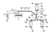
以下、本発明の電源供給装置を図面に基づいて説明する。この電源供給装置1は、ICEV(内燃機関自動車:Internal Combustion Engine Vehicle)に搭載されるものである。図1に示すように、電源供給装置1は、電源としてのバッテリ2と、このバッテリ2などから電源供給を受けて動作する複数の負荷ユニット31〜33と、バッテリ2及び複数の負荷ユニット31〜33間に設けられたオルタネータ4と、バッテリ2に接続された電源線L11及びグランド線L12と複数の負荷ユニット31〜33とを接続するための中継コネクタ5と、を備えている。
First Embodiment Hereinafter, a power supply device of the present invention will be described with reference to the drawings. The
上記バッテリ2は、鉛電池の他、リチウム電池といった二次電池を用いていて、例えば車両のエンジンルームなどに配置されている。上記複数の負荷ユニット31〜33は各々、負荷としてのランプ負荷3aと、これらランプ負荷3aを保持、収容する筐体としてのホルダ3bと、このホルダ3bに一体に設けられたコネクタ3cと、を備えている。これら負荷ユニット31〜33は、車両内において互いに近い場所に配置されている。また、上記コネクタ3cは、ランプ負荷3aの両端に接続される図示しない例えば雌型の端子金具と、これら端子金具を保持するホルダ3bに一体に設けられたハウジングと、から構成されている。
The
上記オルタネータ4は、エンジンの機械エネルギーを電気エネルギーに変換する発電機であり、バッテリ2を充電したり、上述したランプ負荷3aに直接電源を供給する。このオルタネータ4の代わりにバッテリ2からの供給電圧を降圧するDC/DCコンバータ6がバッテリ2と複数の負荷ユニット31〜33との間に接続されることがあるが、ここではオルタネータ4が接続されている場合について説明する。
The
上記中継コネクタ5は、複数の負荷ユニット31〜33のうち1つである負荷ユニット31のコネクタ3cにコネクタ接続されて取り付けられている。この負荷ユニット31には、負荷ユニット31〜33に設けられたランプ負荷3aのうち最も消費電流が大きいランプ負荷3aが設けられている。この中継コネクタ5は、主駆動装置7からの駆動信号の出力に応じて複数の負荷ユニット31〜33に内蔵されたランプ負荷3aに対する電源供給を開始し、駆動信号の出力停止に応じてランプ負荷3aに対する電源供給を遮断する。
The
この中継コネクタ5には、図1(B)に示すように、圧接電源端子51a、圧接グランド端子51b、圧接信号端子51cと、第1分岐回路52aと、第2分岐回路52bと、タブ状電源端子53a、圧接電源端子53b、53cと、タブ状グランド端子54a、圧接グランド端子54b、54cと、を備えている。上記第1端子金具としての圧接電源端子51aには、バッテリ2のプラス側に接続された電源線L11が接続されバッテリ2からの電源のプラス側が入力される。
As shown in FIG. 1B, the
上記圧接グランド端子51bには、バッテリ2のマイナス側に接続されたグランド線L12が接続されバッテリ2からの電源のマイナス側が入力される。上記圧接信号端子51cには、主駆動装置7に接続された信号線L13に接続され駆動信号が入力される。分岐回路としての第1分岐回路52aは、圧接電源端子51aから入力された1つの電源ラインを複数の分岐ラインに分岐する回路である。上記第2分岐回路52bは、圧接グランド端子51bから入力された1つのグランドラインを複数の分岐ラインに分岐する回路である。
A ground line L12 connected to the negative side of the
第2端子金具としてのタブ状電源端子53a、圧接電源端子53b、53cは、第1分岐回路52aによって分岐された複数の分岐ラインに各々接続され、前記各ランプ負荷3aに対して電源のプラス側を出力する。タブ状電源端子53a、圧接電源端子53b、53cは、第2分岐回路52bによって分岐された複数の分岐ラインに各々接続され、各ランプ負荷3aに対して電源のマイナス側を出力する端子である。
The tab-shaped
また、上記中継コネクタ5には、第1分岐回路52aにより分岐された分岐ライン上に各々設けられているスイッチ素子55a〜55cと、圧接電源端子51aから入力された入力電圧VINを各負荷ユニット31〜33に設けられたランプ負荷3aに供給される供給電圧として検出する電圧検出手段としての電圧検出装置56と、駆動信号及び電圧検出装置56の検出結果に基づいてスイッチ素子55a〜55cのオンオフを制御するオンオフ制御手段としての電力制御装置57と、が設けられている。
The
上記スイッチ素子55a〜55cは、例えば半導体リレーなどからなり、オンするとオルタネータ4からの電源をランプ負荷3aに対して供給し、オフするとランプ負荷3aに対するオルタネータ4からの電源の供給を遮断する。
The
上記電圧検出装置56は、例えばOPアンプなどから構成され、検出した電圧を電力制御装置57に対して供給する。上記電力制御装置57は、例えば公知のマイコンなどから構成され、電源供給装置1全体の制御を司る。これら電圧検出装置56及び電力制御装置57は、圧接電源端子51a及び圧接グランド端子51bを介してバッテリ2からの電源の供給を受けて駆動する装置である。
The
また、上記中継コネクタ5は、図2に示すようにこれら端子51a〜51c、53a〜53c、54a〜54cが突出される封止体58と、これら端子51a〜51c、53a〜53c、54a〜54c及び封止体58を収容するハウジング59と、を備えている。
Further, as shown in FIG. 2, the
次に、上記封止体58及びハウジング59の説明をする前に、この封止体58から突出された端子51a〜51c、53a〜53c、54a〜54cの構成について説明する。上記圧接電源端子51a、圧接グランド端子51b、圧接信号端子51c、圧接電源端子53b及び53c、圧接グランド端子54b及び54cは、導電性の金属から構成されていて、一端が後述する封止体58内に挿入され、他端が封止体58の互いに対向する一対の面の一方からそれぞれ突出している。
Next, before describing the sealing
これら圧接電源端子51a、圧接グランド端子51b、圧接信号端子51c、圧接電源端子53b及び53c、圧接グランド端子54b及び54cには、その他端に圧接刃が形成されている。そして、圧接電源端子51aには電源線L11の端末が圧接され、圧接グランド端子51bにはグランド線L12の端末が圧接され、圧接信号端子51cには信号線L13の端末が圧接されている。また、圧接電源端子53b、圧接グランド端子54bには、負荷ユニット33に接続された電線としての電源線L21、グランド線L22の一端が圧接されている。圧接電源端子53c、圧接グランド端子54cには、負荷ユニット32に接続された電線としての電源線L31、グランド線L32の一端が圧接されている。
The pressure
なお、図1に示すように、上記電源線L21、グランド線L22の他端には、コネクタ9が取り付けられていて、このコネクタ9が負荷ユニット33のコネクタ3cにコネクタ接続される。そして、コネクタ9と負荷ユニット33のコネクタ3cとがコネクタ接続されると、電源線L21、グランド線L22が負荷ユニット33のランプ負荷3aの両端に接続される。
As shown in FIG. 1, a
また、上記電源線L31、グランド線L32の他端にはコネクタ9が取り付けられていて、このコネクタ9が負荷ユニット32のコネクタ3cにコネクタ接続される。そして、コネクタ9と負荷ユニット32のコネクタ3cとがコネクタ接続されると、電源線L31、グランド線L32が負荷ユニット32のランプ負荷3aの両端に接続される。
A
また、上記タブ状電源端子53a及びタブ状グランド端子54aは、導電性の金属から構成されていて、一端が後述する封止体58内に挿入され、他端が封止体58の互いに対向する一対の面の他方からそれぞれ突出している。タブ状電源端子53a及びタブ状グランド端子54aの他端は、タブ状に形成されていて、負荷ユニット31のコネクタ3cに設けられた雌型の端子金具に嵌合する。
The tab-shaped
次に、封止体58及びハウジング59について説明する。封止体58は、上記第1分岐回路52a、第2分岐回路52b、スイッチ素子55a〜55c、電圧検出装置56及び電力制御装置57が搭載されたチップ58aと、これら端子51a〜51c、53a〜53c、54a〜54cと、をワイヤボンディングして接続した状態で、樹脂封止している。
Next, the sealing
上記ハウジング59は、これら端子51a〜51c、53a〜53c、54a〜54c及び封止体58を収容している。上記ハウジング59は、扁平な四角筒状に設けられていて、一方の開口から圧接電源端子51a、圧接グランド端子51b、圧接信号端子51c、圧接電源端子53b及び53c、圧接グランド端子54b及び54cが露出され、他方の開口からタブ状電源端子53a及びタブ状グランド端子54aが露出されている。また、ハウジング59の筒長さ方向の他方には、負荷ユニット31に設けたコネクタ3cのハウジングが進入し嵌合するフード部59aが設けられている。このフード部59aに負荷ユニット31に設けたコネクタ3cのハウジングが進入されると、タブ状電源端子53a及びタブ状グランド端子54aにコネクタ3cの端子金具が接続される。
The
次に、上述した構成の電源供給装置1の動作について図3及び図4を参照して以下説明する。図3は、図1に示す電源供給装置1を構成する電力制御装置57のフローチャートである。図4(A)は図1に示す電源供給装置1を構成する中継コネクタ5の圧接電源端子51aから入力される入力電圧VINのタイムチャートであり、図4(B)は図1に示す電源供給装置1を構成するタブ状電源端子53a、圧接電源端子53b、53cから出力される出力電圧VOUTのタイムチャートである。
Next, the operation of the
また、電力制御装置57は、主駆動装置7からの駆動信号の入力に応じて動作を開始する。最初に、電力制御装置57は、図3に示すように、主駆動装置7からの駆動信号がオフになっているか否かを判断する(ステップS1)。オフになっていれば(ステップS1でY)、電力制御装置57はスイッチ素子55a〜55cに対する制御信号の出力を停止してスイッチ素子55a〜55cを常時オフ制御した後(ステップS2)、処理を終了する。これに対して、オフになっていなければ(ステップS1でN)、電力制御装置57はステップS3に進む。
Further, the
ステップS3において電力制御装置57は、電圧検出装置56により検出された入力電圧VINを取り込む。次に、電力制御装置57は、ステップS3で取り込んだ入力電圧VINが予め設定されたランプ負荷3aの定格電圧(所定値)を超えたか否かを判定する(ステップS4)。
In step S <b> 3, the
入力電圧VINが定格電圧以下であれば(ステップS4でN)、電力制御装置57は、スイッチ素子55a〜55cを常時オンする制御信号を出力した後(ステップS5)、処理を終了する。
If the input voltage V IN is equal to or lower than the rated voltage (N in Step S4), the
これに対して入力電圧VINが定格電圧を超えていれば(ステップS4でY)、電力制御装置57は、スイッチ素子55a〜55cを常時オンせずに間欠的にオン制御するパルス状の制御信号を出力した後(ステップS6)、処理を終了する。ステップS6において、電力制御装置57は、入力電圧VINが高いほどスイッチ素子55a〜55cのオン期間のデューティ比を小さくする。ここでオン期間のデューティ比とは、(スイッチ素子55a〜55cのオン期間)/(スイッチ素子55a〜55cがオンされる周期)を示す。
On the other hand, if the input voltage V IN exceeds the rated voltage (Y in step S4), the
上述した動作によれば、図4に示すように、入力電圧VINが定格電圧以下の間はランプ負荷3aに対して常時電源が供給され、入力電圧VINが定格電圧を超えると間欠的にランプ負荷3aに電力が供給されるようになる。このとき、入力電圧VINが高くなるに従ってオン期間のデューティ比が小さくなる。
According to the above-described operation, as shown in FIG. 4, the power is always supplied to the
このため、入力電圧VINとランプ負荷3aに供給される電力POUTとの関係は図5に示すようになる。即ち、入力電圧VINが定格電圧より低い間、スイッチ素子55a〜55cは電力制御装置57によって常時オン制御されるため、入力電圧VINが増えるほど電力も増加する。入力電圧VINが定格を超えると、スイッチ素子55a〜55cは電力制御装置57によって間欠的にオン制御され、しかも入力電圧VINが高くなるに従ってオン期間が短くなるので、電力POUTを一定に抑えることができる。
For this reason, the relationship between the input voltage V IN and the power P OUT supplied to the
上述した電源供給装置1によれば、第1分岐回路52aを内蔵した中継コネクタ5を複数のランプ負荷3aを収容するホルダ3bに取り付けることにより、バッテリ2−中継コネクタ5間の太くて線路抵抗の少ない電源線L11の長さを長くし、中継コネクタ5−負荷ユニット31に設けられたランプ負荷3aまでの細くて経路抵抗の大きい経路を短くすることができる。また、負荷ユニット31〜33は互いに近接配置されているため、中継コネクタ5−負荷ユニット32、33に設けられたランプ負荷3aまでの細くて経路抵抗の大きい電源線L21、L31も極力短くすることができる。このため、電線による電力ロスを抑えることができる。
According to the
また、上述した電源供給装置1によれば、消費電流が最も多いランプ負荷3aを内蔵した負荷ユニット31に中継コネクタ5を取り付けているため、より一層電力ロスを抑えることができる。
Moreover, according to the
また、上述した電源供給装置1によれば、第1分岐回路51aが中継コネクタ5内に内蔵されているため、簡単に電源供給装置1に取り付けることができる。
Further, according to the
また、上述した電源供給装置1によれば、電力制御装置57が、間欠的にスイッチ素子55a〜55cをオン制御すると共に、電圧検出装置56により検出された入力電圧VINが大きくなるに従ってスイッチ素子55a〜55cのオン期間のデューティ比を小さくする。即ち、入力電圧VINが大きくなるほどスイッチ素子55a〜55cのオン期間を短くすることにより、電力としては一定に抑えることができる。これにより一定以上の無駄な電力が供給されることがなく、省電力化、長寿命化を図ることができる。しかも、上述したように中継コネクタ5−各ランプ負荷3aまでの経路を極力短くすることができるため、正確にランプ負荷3aに供給される供給電圧を検出することができる。
Further, according to the
また、上述した中継コネクタ5によれば、電力制御装置57が、電圧検出装置56により検出された入力電圧VINが定格電圧以下のときスイッチ素子55a〜55cを常時オン制御し、入力電圧VINが定格電圧を超えたときスイッチ素子55a〜55cを間欠的にオン制御するので、ランプ負荷3aの機能を最大限に生かすことができる。
Further, according to the
また、上述した中継コネクタ5によれば、バッテリ2に並列接続されたオルタネータ4又はDC/DCコンバータ6をさらに備え、スイッチ素子55a〜55cが、オルタネータ4又はDC/DCコンバータ6よりもランプ負荷3a側に設けられている。従って、オルタネータ4の場合、エンジン負荷が低減するために、オルタネータ4の発電トルク低減による省電力化を図り、燃費消費低減に貢献できる。また、DC/DCコンバータ6の場合、出力電圧が低減しバッテリ2の消費量の低減を図ることができる。
Further, according to the
なお、上述した実施形態によれば、圧接グランド端子51bから入力したグランド電圧を分岐させてタブ状グランド端子54a、圧接グランド端子54b、54cから出力させて、各ランプ負荷3aに供給していたが、本発明はこれに限ったものではない。例えば、別ルートでランプ負荷3aにグランド電圧を供給できる場合は、第2分岐回路52b、タブ状グランド端子54a、圧接グランド端子54b、54cを設けなくてもよい。また、別ルートでランプ負荷3aにグランド電圧を供給できる場合は、圧接グランド端子51bを廃止して、タブ状グランド端子54a、圧接グランド端子54b、54cの何れか1つを残して、複数のランプ負荷3aの1つからグランド電圧を入力してもよい。
According to the above-described embodiment, the ground voltage input from the press
第2実施形態
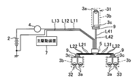
なお、上述した第1実施形態では、中継コネクタ5を負荷ユニット31のホルダ3bに取り付けることにより、中継コネクタ5を複数のランプ負荷3a近傍に配置していたが、本発明はこれに限ったものではない。上記中継コネクタ5としては、バッテリ2の位置と複数のランプ負荷3aの位置との中間よりも複数のランプ負荷3aに近い位置に配置されていればよく、例えば、図6に示すように、中継コネクタ5と負荷ユニット31との間を電線としての電源線L41、グランド線L41で接続して、全ての負荷ユニット31と中継コネクタ5とを電線で接続するようにしてもよい。なお、この場合、電源端子53a及びグランド端子54bはタブ状ではなく、圧接刃が形成され、電源線L41、グランド線L41が圧接される。
Second Embodiment In the first embodiment described above, the
第3実施形態
また、例えば、各負荷ユニット31〜33が図7に示すように配置されていた場合、図7に示すように、各負荷ユニット31〜33の配置位置の中心に中継コネクタ5を配置して、電源線L21、L31、L41、グランド線L22、L32、L42が配索可能な範囲において複数の電源線L21、L31、L41、グランド線L22、L32、L42の合計電線長が最短となる位置に、中継コネクタ5が配置されるようにしてもよい。
3rd Embodiment Moreover, when each load unit 31-33 is arrange | positioned as shown in FIG. 7, for example, as shown in FIG. 7, the
第4実施形態
また、例えば、負荷ユニット32、33のランプ負荷3aが50Wで、負荷ユニット31のランプ負荷3aが25Wであるとすると、図8に示すように、負荷ユニット32、33の配置位置の中心に中継コネクタ5を配置して、電源線L21、L31、L41、グランド線L22、L32、L42が配索可能な範囲において複数の電源線L21、L31、L41、グランド線L22、L32、L42の合計電力損失が最小となる位置に、中継コネクタ5が配置されるようにしてもよい。
Fourth Embodiment Also, for example, assuming that the
第5実施形態
また、例えば、図9に示すように、負荷ユニット32、33に複数のランプ負荷3aが内蔵され、中継コネクタ5と負荷ユニット32、33との間を複数の電源線L41、L21、グランド線L42、L22で接続する場合、負荷ユニット31、32の配置位置の中心に中継コネクタ5を配置して、中電源線L21、L31、L41、グランド線L22、L32、L42が配索可能な範囲において複数の電源線L21、L31、L41、グランド線L22、L32、L42の合計重量が最小となる位置に、中継コネクタ5が配置されるようにしてもよい。
Fifth Embodiment Also, for example, as shown in FIG. 9, a plurality of
第6実施形態
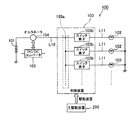
次に、第6実施形態の電源供給装置1について図10〜図12を参照して説明する。図10は、本発明の電源供給装置1の第6実施形態を示す回路図である。図11は、図10に示す中継コネクタ5の断面図である。図12は、図10に示す電源供給装置1が構成する電力制御装置のフローチャートである。
Sixth Embodiment Next, a
上述した第1実施形態では、ランプ負荷3aのオンオフ駆動と、入力電圧VINに応じたデューティ制御と、を中継コネクタ5で行っていたが、本発明はこれに限ったものではない。例えば、図10に示すように、バッテリ2やオルタネータ4と、中継コネクタ5と、の間にスイッチ素子8を設け、ランプ負荷3aのオンオフ駆動をスイッチ素子8で行い、デューティ制御を中継コネクタ5で行うようにしてもよい。
In the first embodiment described above, the on / off drive of the
上記スイッチ素子8は、例えば、メカリレー、半導体リレーからなり、主駆動装置7からの駆動信号の出力に応じてオンしてランプ負荷3aや中継コネクタ5に内蔵された電圧検出装置56や電力制御装置57に対する電源供給を開始し、主駆動装置7からの駆動信号の出力停止に応じてオフしてランプ負荷3aや中継コネクタ5に内蔵された電圧検出装置56や電力制御装置57に対する電源供給を遮断する。
The
そして、中継コネクタ5においては、第1実施形態と異なり電力制御装置57には駆動信号が供給されていない。従って、図11に示すように、第1実施形態とは異なり中継コネクタ5には駆動信号を入力するための圧接信号端子51cが備えられていない。
In the
次に、上述した構成の第2実施形態における電源供給装置1の動作について図12に示すフローチャートを参照して説明する。まず、主駆動装置7から駆動信号が入力すると、スイッチ素子8がオンして、電圧検出装置56や電力制御装置57に対する電源供給が開始され、電力制御装置57が動作を開始する。
Next, the operation of the
第1実施形態では、電力制御装置57は、ステップS1で駆動信号の状態を確認していたが、第6実施形態では、ステップS1及びS2の動作を行わずに直ちにステップS3〜S6に進む。ステップS3〜S6については、上述した第1実施形態で既に説明したので、ここでは詳細な説明を省略する。
In the first embodiment, the
なお、図10については、第1実施形態を適用した例を示しているが、第2〜第5実施形態にも適用することができる。 Although FIG. 10 shows an example in which the first embodiment is applied, it can also be applied to the second to fifth embodiments.
また、上述した第1〜第6実施形態によれば、電力制御装置57は、複数のスイッチ素子55a〜55cを一括で制御していたが、本発明はこれに限ったものではない。主駆動装置7からランプ負荷3a毎の駆動信号が出力される場合や、ランプ負荷3aの定格電圧が異なる場合などは、複数のスイッチ素子55a〜55cを互いに独立して制御するようにしてもよい。
Further, according to the first to sixth embodiments described above, the
また、上述した第1〜第6及び第2実施形態によれば、電力制御装置57により各スイッチ素子55a〜55cのデューティ比を制御していたが、本発明はこれに限ったものではない。電力制御装置57としては、単に駆動信号が供給されたときにスイッチ素子55a〜55cを常時オン、駆動信号の供給が停止されたときにスイッチ素子55a〜55cを常時オフさせてもよい。また、中継コネクタ5内には、スイッチ素子55a〜55c、電圧検出装置56及び電力制御装置57を設けていたが、本発明はこれに限ったものではない。中継コネクタ5内には少なくとも圧接電源端子51a、第1分岐回路52a、タブ状電源端子53aが設けられていればよく、スイッチ素子55a〜55c、電圧検出装置56及び電力制御装置57は必須ではない。
Further, according to the first to sixth and second embodiments described above, the duty ratios of the
また、上述した第1〜第6実施形態では、バッテリ2とランプ負荷3aとの間にオルタネータ4が設けられていたが、本発明はこれに限ったものではない。オルタネータ4としては、バッテリ2に並列接続していればよく、ICEVによっては、図13(A)に示す構成の電源供給装置1もあるが、このような場合にも適用できる。
In the first to sixth embodiments described above, the
また、上述した実施形態によれば、中継コネクタ5の一方から突出する端子51a〜51c、53b、53c、54b、54cに圧接刃を形成し、他方から突出する端子53a、54aをタブ状に形成していが、端子51a〜51c、53a〜53c、54a〜54cの形状はこれに限定されるものではない。
Further, according to the above-described embodiment, the press contact blades are formed on the
また、上述した実施形態では、負荷としてランプ負荷3aを挙げて説明していたが、本発明はこれに限ったものではない。負荷としては、バッテリ2から電源供給を受けて駆動するものであればよく、他にモータなどであってもよい。
In the embodiment described above, the
また、上述した実施形態では、バッテリ2とランプ負荷3aとの間にDC/DCコンバータ6が設けられていたが、本発明はこれに限ったものではない。DC/DCコンバータ6としては、バッテリ2に並列接続していればよく、図13(B)に示すように、2つのバッテリ2、11とジェネレータ10とが設けられた電源供給装置1を搭載するHEV(ハイブリッド電気自動車:Hybrid Electric Vehicle)及びPHEV(プラグインハイブリッド自動車:Plug-In Hybrid Electric Vehicle)にも適用できる。また、図13(C)に示すように2つのバッテリ2、11が設けられた電源供給装置1を搭載するBEV(電池自動車:Battery Electric Vehicle)やFCEV(燃料電池自動車:Fuel Cell Electric Vehicle)にも適用できる。
In the above-described embodiment, the DC /
なお、図13については、第1実施形態を適用した例を示しているが、第2〜第6実施形態にも適用することができる。 Note that FIG. 13 shows an example in which the first embodiment is applied, but the present invention can also be applied to the second to sixth embodiments.
また、上述した実施形態によれば、第1分岐回路52aが中継コネクタ5内に内蔵されていたが、本発明はこれに限ったものではない。中継コネクタ5に内蔵されていなくてもよい。
Further, according to the above-described embodiment, the
また、前述した実施形態は本発明の代表的な形態を示したに過ぎず、本発明は、実施形態に限定されるものではない。即ち、本発明の骨子を逸脱しない範囲で種々変形して実施することができる。 Further, the above-described embodiments are merely representative forms of the present invention, and the present invention is not limited to the embodiments. That is, various modifications can be made without departing from the scope of the present invention.
1 電源供給装置
2 バッテリ(電源)
3a ランプ負荷(負荷)
3b ホルダ(筐体)
5 中継コネクタ
51a 圧接電源端子(第1端子金具)
52a 第1分岐回路(分岐回路)
53a タブ状電源端子(第2端子金具)
53b 圧接電源端子(第2端子金具)
53c 圧接電源端子(第2端子金具)
55a スイッチ素子
55b スイッチ素子
55c スイッチ素子
56 電圧検出装置(電圧検出手段)
57 電力制御装置(オンオフ制御手段)
59 ハウジング
L21 電源線(電線)
L31 電源線(電線)
L41 電源線(電線)
1
3a Lamp load (load)
3b Holder (housing)
5
52a First branch circuit (branch circuit)
53a Tab-shaped power supply terminal (second terminal fitting)
53b Pressure contact terminal (second terminal fitting)
53c Pressure welding power supply terminal (second terminal fitting)
57 Power control device (on / off control means)
59 Housing L21 Power line (electric wire)
L31 Power line (electric wire)
L41 Power line (electric wire)
Claims (5)
前記電源に接続された1つの電源ラインを前記複数の負荷に供給するために複数の分岐ラインに分岐する分岐回路と、
前記電源に接続された第1端子金具と、前記負荷それぞれ接続された複数の第2端子金具と、これら前記第1端子金具及び前記第2端子金具を収容するコネクタハウジングと、が設けられた中継コネクタと、を備え、
前記分岐回路が、前記第1端子金具及び前記第2端子金具に接続された状態で前記コネクタハウジング内に収容され、
前記中継コネクタのコネクタハウジング内には、前記分岐ライン上に各々設けられた複数のスイッチ素子と、前記第1端子金具から入力された前記各負荷に供給された供給電圧を検出する電圧検出手段と、前記スイッチ素子を間欠的にオン制御すると共に前記電圧検出手段により検出された供給電圧が大きくなるに従って前記スイッチ素子のオン期間のデューティ比を小さくするオンオフ制御手段と、がさらに収容されている
ことを特徴とする電源供給装置。 In a power supply device comprising a power supply and a plurality of loads that receive power supply from the power supply,
A branch circuit that branches into a plurality of branch lines to supply one power line connected to the power source to the plurality of loads ;
A relay provided with a first terminal fitting connected to the power source, a plurality of second terminal fittings connected to each of the loads, and a connector housing for housing the first terminal fitting and the second terminal fitting. A connector, and
The branch circuit is accommodated in the connector housing in a state of being connected to the first terminal fitting and the second terminal fitting,
In the connector housing of the relay connector, a plurality of switch elements respectively provided on the branch line, and voltage detection means for detecting a supply voltage supplied to the loads input from the first terminal fittings And an on / off control means for intermittently controlling the switch element on and reducing the duty ratio of the on-period of the switch element as the supply voltage detected by the voltage detection means increases.
A power supply device.
ことを特徴とする請求項1に記載の電源供給装置。 The power supply device according to claim 1 , wherein the branch circuit is disposed at a position closer to the plurality of loads than an intermediate position between the position of the power source and the positions of the plurality of loads.
前記電線が配索可能な範囲において前記複数の電線の合計電線長が最短となる位置に、前記分岐回路が配置されている
ことを特徴とする請求項1に記載の電源供給装置。 A plurality of electric wires connecting the branch circuit and the plurality of loads;
Power supply device according to claim 1, wherein the wire has a total wire length of the plurality of electric wires in cabling possible range is in a position to be the shortest, characterized in that the branch circuit is arranged.
前記電線が配索可能な範囲において前記複数の電線の合計電力損失が最小となる位置に、前記分岐回路が配置されている
ことを特徴とする請求項1に記載の電源供給装置。 A plurality of electric wires connecting the branch circuit and the plurality of loads;
Power supply device according to claim 1, wherein the wire is in a position that the total power loss of said plurality of wires at the minimum wiring extent possible, wherein the branch circuit is arranged.
前記電線が配索可能な範囲において前記複数の電線の合計重量が最小となる位置に、前記分岐回路が配置されている
ことを特徴とする請求項1に記載の電源供給装置。 A plurality of electric wires connecting the branch circuit and the plurality of loads;
Power supply device according to claim 1, wherein the wire is in a position where the total weight of the plurality of wires at the minimum wiring extent possible, wherein the branch circuit is arranged.
Priority Applications (5)
| Application Number | Priority Date | Filing Date | Title |
|---|---|---|---|
| JP2011175840A JP5892533B2 (en) | 2011-08-11 | 2011-08-11 | Power supply device |
| CN201280049906.1A CN103875152A (en) | 2011-08-11 | 2012-08-03 | Power supply device |
| EP12822736.0A EP2744064B1 (en) | 2011-08-11 | 2012-08-03 | Power supply device |
| PCT/JP2012/069797 WO2013021928A1 (en) | 2011-08-11 | 2012-08-03 | Power supply device |
| US14/177,701 US9545889B2 (en) | 2011-08-11 | 2014-02-11 | Power supply unit |
Applications Claiming Priority (1)
| Application Number | Priority Date | Filing Date | Title |
|---|---|---|---|
| JP2011175840A JP5892533B2 (en) | 2011-08-11 | 2011-08-11 | Power supply device |
Publications (3)
| Publication Number | Publication Date |
|---|---|
| JP2013042563A JP2013042563A (en) | 2013-02-28 |
| JP2013042563A5 JP2013042563A5 (en) | 2014-04-10 |
| JP5892533B2 true JP5892533B2 (en) | 2016-03-23 |
Family
ID=47668436
Family Applications (1)
| Application Number | Title | Priority Date | Filing Date |
|---|---|---|---|
| JP2011175840A Active JP5892533B2 (en) | 2011-08-11 | 2011-08-11 | Power supply device |
Country Status (5)
| Country | Link |
|---|---|
| US (1) | US9545889B2 (en) |
| EP (1) | EP2744064B1 (en) |
| JP (1) | JP5892533B2 (en) |
| CN (1) | CN103875152A (en) |
| WO (1) | WO2013021928A1 (en) |
Families Citing this family (11)
| Publication number | Priority date | Publication date | Assignee | Title |
|---|---|---|---|---|
| CN105656096A (en) * | 2014-11-14 | 2016-06-08 | 江苏永昌新能源科技有限公司 | Electric car lithium battery mounting casing |
| FR3041579B1 (en) * | 2015-09-24 | 2017-10-13 | Vignal Systems | VEHICLE REAR LIGHT AND SYSTEM FOR CONTROLLING AN ACCESSORY OF A VEHICLE |
| CN106593148B (en) * | 2015-10-16 | 2019-04-05 | 联合汽车电子有限公司 | Passenger car doorlock control unit |
| JP6387040B2 (en) | 2016-04-28 | 2018-09-05 | 矢崎総業株式会社 | Vehicle power control device |
| JP6646540B2 (en) | 2016-07-13 | 2020-02-14 | 矢崎総業株式会社 | Vehicle power control device |
| JP2018127148A (en) | 2017-02-09 | 2018-08-16 | 矢崎総業株式会社 | Vehicle power source control device |
| JP6836925B2 (en) | 2017-02-09 | 2021-03-03 | 矢崎総業株式会社 | Vehicle power control unit |
| JP6836414B2 (en) | 2017-02-09 | 2021-03-03 | 矢崎総業株式会社 | Vehicle power control unit |
| JP7140725B2 (en) * | 2019-07-31 | 2022-09-21 | 本田技研工業株式会社 | power supply |
| EP3786649A1 (en) * | 2019-08-29 | 2021-03-03 | Siemens Aktiengesellschaft | Method for checking load circuits in a technical installation |
| KR102512377B1 (en) * | 2021-08-10 | 2023-03-21 | 현대모비스 주식회사 | Led driver module and car including the same |
Family Cites Families (20)
| Publication number | Priority date | Publication date | Assignee | Title |
|---|---|---|---|---|
| JPS54159934A (en) * | 1978-06-09 | 1979-12-18 | Yazaki Corp | Wireering system of automobile |
| JPS5780681A (en) * | 1980-11-10 | 1982-05-20 | Hitachi Ltd | Concentrated wiring device for vehicle |
| GB9406625D0 (en) * | 1994-04-05 | 1994-05-25 | Smiths Industries Plc | Electrical systems and connectors |
| EP0692850B1 (en) * | 1994-07-15 | 2003-03-12 | Sumitomo Wiring Systems, Ltd. | Electrical connection box |
| US5604385A (en) * | 1995-05-22 | 1997-02-18 | Target Hi-Tech Electronics Ltd. | Apparatus for and method of evenly distributing an electrical load across a three phase power distribution network |
| US6144110A (en) * | 1997-03-19 | 2000-11-07 | The Furukawa Electric Co., Ltd. | Vehicular use power distribution apparatus and vehicular use power source apparatus |
| DE19739410C1 (en) * | 1997-08-28 | 1998-12-17 | Volkswagen Bordnetze Gmbh | Electrical circuit for the network on board a motor vehicle |
| JP2002200948A (en) * | 2000-12-28 | 2002-07-16 | Denso Corp | Vehicular power distribution device |
| JP3713477B2 (en) | 2001-11-19 | 2005-11-09 | Tdk株式会社 | Power line communication system |
| JP2003212065A (en) * | 2002-01-24 | 2003-07-30 | Yazaki Corp | Power supply device and joint connector |
| JP3794564B2 (en) * | 2002-02-08 | 2006-07-05 | 古河電気工業株式会社 | Power control device |
| US6972375B2 (en) * | 2002-10-21 | 2005-12-06 | Denso Corporation | Wiring harness |
| JP2004259582A (en) * | 2003-02-26 | 2004-09-16 | Yazaki Corp | Lamp control circuit and lamp control method |
| US6768647B1 (en) * | 2003-03-19 | 2004-07-27 | Lear Corporation | Wireless RF/serial remote zone connector and system |
| DE10341838A1 (en) * | 2003-09-09 | 2005-04-28 | Siemens Ag | Method for controlling energy flows |
| JP2005297860A (en) * | 2004-04-14 | 2005-10-27 | Toyota Motor Corp | Power supply device for vehicle |
| JP2008298536A (en) | 2007-05-30 | 2008-12-11 | Canon Inc | Connection detecting device |
| JP5144160B2 (en) * | 2007-07-26 | 2013-02-13 | パナソニック株式会社 | In-vehicle load control device, in-vehicle headlamp device, and in-vehicle taillight device |
| JP5170888B2 (en) * | 2008-08-01 | 2013-03-27 | 古河電気工業株式会社 | Vehicle power supply device and vehicle power supply method |
| JP2010192240A (en) * | 2009-02-18 | 2010-09-02 | Sumitomo Wiring Syst Ltd | Wire harness with semiconductor relay module |
-
2011
- 2011-08-11 JP JP2011175840A patent/JP5892533B2/en active Active
-
2012
- 2012-08-03 EP EP12822736.0A patent/EP2744064B1/en active Active
- 2012-08-03 CN CN201280049906.1A patent/CN103875152A/en active Pending
- 2012-08-03 WO PCT/JP2012/069797 patent/WO2013021928A1/en unknown
-
2014
- 2014-02-11 US US14/177,701 patent/US9545889B2/en active Active
Also Published As
| Publication number | Publication date |
|---|---|
| US9545889B2 (en) | 2017-01-17 |
| CN103875152A (en) | 2014-06-18 |
| JP2013042563A (en) | 2013-02-28 |
| WO2013021928A1 (en) | 2013-02-14 |
| US20140159482A1 (en) | 2014-06-12 |
| EP2744064A1 (en) | 2014-06-18 |
| EP2744064B1 (en) | 2018-07-25 |
| EP2744064A4 (en) | 2015-11-25 |
Similar Documents
| Publication | Publication Date | Title |
|---|---|---|
| JP5892533B2 (en) | Power supply device | |
| KR102478091B1 (en) | Battery charge controlling system and method for vehicle | |
| JP5713102B2 (en) | Vehicle power supply | |
| CN108569154A (en) | Vehicle and method for charging electric vehicles | |
| JP6204797B2 (en) | Vehicle power supply | |
| US10199945B2 (en) | Battery unit | |
| US20130249522A1 (en) | Power Supply Control Device | |
| JP4747933B2 (en) | Power supply device and vehicle equipped with the same | |
| JP4941461B2 (en) | In-vehicle charger | |
| JP2013150524A (en) | Electric vehicle | |
| JP6944058B2 (en) | Vehicle charger with DC / DC converter | |
| JP6953634B2 (en) | Vehicle charger with DC / DC converter | |
| KR102171985B1 (en) | Emergency power supply device for eco-friendly vehicle | |
| JP2008296797A (en) | Power source device for vehicle | |
| CN116438734A (en) | Vehicle electrical system | |
| EP3683088B1 (en) | Vehicle power supply system | |
| JP5629667B2 (en) | Multi-phase converter | |
| JP2007020283A (en) | Power control system for vehicle | |
| JP7465801B2 (en) | Power supply system and mobile body | |
| JP2008252987A (en) | Power supply system | |
| CN215268043U (en) | Electric vehicle controller with voltage output function and electric vehicle | |
| JPH10304580A (en) | Power source equipment | |
| JP2013121290A (en) | Load control system | |
| JP2010259229A (en) | Power supply device system | |
| JP2021044874A (en) | Power control device |
Legal Events
| Date | Code | Title | Description |
|---|---|---|---|
| A521 | Request for written amendment filed |
Free format text: JAPANESE INTERMEDIATE CODE: A523 Effective date: 20140226 |
|
| A621 | Written request for application examination |
Free format text: JAPANESE INTERMEDIATE CODE: A621 Effective date: 20140718 |
|
| A131 | Notification of reasons for refusal |
Free format text: JAPANESE INTERMEDIATE CODE: A131 Effective date: 20150331 |
|
| A521 | Request for written amendment filed |
Free format text: JAPANESE INTERMEDIATE CODE: A523 Effective date: 20150512 |
|
| A131 | Notification of reasons for refusal |
Free format text: JAPANESE INTERMEDIATE CODE: A131 Effective date: 20150908 |
|
| A521 | Request for written amendment filed |
Free format text: JAPANESE INTERMEDIATE CODE: A523 Effective date: 20151015 |
|
| TRDD | Decision of grant or rejection written | ||
| A01 | Written decision to grant a patent or to grant a registration (utility model) |
Free format text: JAPANESE INTERMEDIATE CODE: A01 Effective date: 20160209 |
|
| A61 | First payment of annual fees (during grant procedure) |
Free format text: JAPANESE INTERMEDIATE CODE: A61 Effective date: 20160217 |
|
| R150 | Certificate of patent or registration of utility model |
Ref document number: 5892533 Country of ref document: JP Free format text: JAPANESE INTERMEDIATE CODE: R150 |
|
| R250 | Receipt of annual fees |
Free format text: JAPANESE INTERMEDIATE CODE: R250 |
|
| R250 | Receipt of annual fees |
Free format text: JAPANESE INTERMEDIATE CODE: R250 |
|
| R250 | Receipt of annual fees |
Free format text: JAPANESE INTERMEDIATE CODE: R250 |
|
| R250 | Receipt of annual fees |
Free format text: JAPANESE INTERMEDIATE CODE: R250 |
|
| R250 | Receipt of annual fees |
Free format text: JAPANESE INTERMEDIATE CODE: R250 |
|
| S531 | Written request for registration of change of domicile |
Free format text: JAPANESE INTERMEDIATE CODE: R313531 |
|
| R350 | Written notification of registration of transfer |
Free format text: JAPANESE INTERMEDIATE CODE: R350 |
|
| R250 | Receipt of annual fees |
Free format text: JAPANESE INTERMEDIATE CODE: R250 |