EP3146944B1 - Handgelenksorthese - Google Patents
Handgelenksorthese Download PDFInfo
- Publication number
- EP3146944B1 EP3146944B1 EP16189941.4A EP16189941A EP3146944B1 EP 3146944 B1 EP3146944 B1 EP 3146944B1 EP 16189941 A EP16189941 A EP 16189941A EP 3146944 B1 EP3146944 B1 EP 3146944B1
- Authority
- EP
- European Patent Office
- Prior art keywords
- flame
- textile layer
- fibre component
- resistant
- bearing part
- Prior art date
- Legal status (The legal status is an assumption and is not a legal conclusion. Google has not performed a legal analysis and makes no representation as to the accuracy of the status listed.)
- Active
Links
- 210000000707 wrist Anatomy 0.000 title description 22
- 239000004753 textile Substances 0.000 claims 22
- 239000000835 fiber Substances 0.000 claims 14
- 238000000034 method Methods 0.000 claims 9
- 239000000463 material Substances 0.000 claims 5
- 229920003043 Cellulose fiber Polymers 0.000 claims 3
- 239000004372 Polyvinyl alcohol Substances 0.000 claims 3
- 238000010018 discharge printing Methods 0.000 claims 3
- 229920002451 polyvinyl alcohol Polymers 0.000 claims 3
- 230000001681 protective effect Effects 0.000 claims 3
- 229920001059 synthetic polymer Polymers 0.000 claims 3
- 239000007864 aqueous solution Substances 0.000 claims 2
- 229920003235 aromatic polyamide Polymers 0.000 claims 2
- 229920000877 Melamine resin Polymers 0.000 claims 1
- 229920002821 Modacrylic Polymers 0.000 claims 1
- 229920006282 Phenolic fiber Polymers 0.000 claims 1
- 239000004952 Polyamide Substances 0.000 claims 1
- 230000002378 acidificating effect Effects 0.000 claims 1
- 239000004760 aramid Substances 0.000 claims 1
- 125000003118 aryl group Chemical group 0.000 claims 1
- 238000004043 dyeing Methods 0.000 claims 1
- 238000004519 manufacturing process Methods 0.000 claims 1
- JDSHMPZPIAZGSV-UHFFFAOYSA-N melamine Chemical compound NC1=NC(N)=NC(N)=N1 JDSHMPZPIAZGSV-UHFFFAOYSA-N 0.000 claims 1
- 239000000203 mixture Substances 0.000 claims 1
- 229920002647 polyamide Polymers 0.000 claims 1
- XLYOFNOQVPJJNP-UHFFFAOYSA-N water Substances O XLYOFNOQVPJJNP-UHFFFAOYSA-N 0.000 claims 1
- 210000003811 finger Anatomy 0.000 description 30
- 210000000245 forearm Anatomy 0.000 description 5
- 210000003813 thumb Anatomy 0.000 description 3
- 230000006835 compression Effects 0.000 description 2
- 238000007906 compression Methods 0.000 description 2
- 206010023201 Joint contracture Diseases 0.000 description 1
- 206010062575 Muscle contracture Diseases 0.000 description 1
- 230000006978 adaptation Effects 0.000 description 1
- 238000004873 anchoring Methods 0.000 description 1
- 208000006111 contracture Diseases 0.000 description 1
- 230000006735 deficit Effects 0.000 description 1
- 239000006260 foam Substances 0.000 description 1
- 210000004932 little finger Anatomy 0.000 description 1
- 239000002184 metal Substances 0.000 description 1
- 230000000926 neurological effect Effects 0.000 description 1
- 230000000399 orthopedic effect Effects 0.000 description 1
- 230000002265 prevention Effects 0.000 description 1
- 230000000306 recurrent effect Effects 0.000 description 1
- 230000007704 transition Effects 0.000 description 1
Images


Classifications
-
- A—HUMAN NECESSITIES
- A61—MEDICAL OR VETERINARY SCIENCE; HYGIENE
- A61F—FILTERS IMPLANTABLE INTO BLOOD VESSELS; PROSTHESES; DEVICES PROVIDING PATENCY TO, OR PREVENTING COLLAPSING OF, TUBULAR STRUCTURES OF THE BODY, e.g. STENTS; ORTHOPAEDIC, NURSING OR CONTRACEPTIVE DEVICES; FOMENTATION; TREATMENT OR PROTECTION OF EYES OR EARS; BANDAGES, DRESSINGS OR ABSORBENT PADS; FIRST-AID KITS
- A61F5/00—Orthopaedic methods or devices for non-surgical treatment of bones or joints; Nursing devices; Anti-rape devices
- A61F5/01—Orthopaedic devices, e.g. splints, casts or braces
- A61F5/04—Devices for stretching or reducing fractured limbs; Devices for distractions; Splints
- A61F5/05—Devices for stretching or reducing fractured limbs; Devices for distractions; Splints for immobilising
- A61F5/058—Splints
- A61F5/05841—Splints for the limbs
- A61F5/05858—Splints for the limbs for the arms
- A61F5/05866—Splints for the limbs for the arms for wrists, hands, fingers or thumbs
-
- A—HUMAN NECESSITIES
- A61—MEDICAL OR VETERINARY SCIENCE; HYGIENE
- A61F—FILTERS IMPLANTABLE INTO BLOOD VESSELS; PROSTHESES; DEVICES PROVIDING PATENCY TO, OR PREVENTING COLLAPSING OF, TUBULAR STRUCTURES OF THE BODY, e.g. STENTS; ORTHOPAEDIC, NURSING OR CONTRACEPTIVE DEVICES; FOMENTATION; TREATMENT OR PROTECTION OF EYES OR EARS; BANDAGES, DRESSINGS OR ABSORBENT PADS; FIRST-AID KITS
- A61F5/00—Orthopaedic methods or devices for non-surgical treatment of bones or joints; Nursing devices; Anti-rape devices
- A61F5/01—Orthopaedic devices, e.g. splints, casts or braces
- A61F5/0102—Orthopaedic devices, e.g. splints, casts or braces specially adapted for correcting deformities of the limbs or for supporting them; Ortheses, e.g. with articulations
- A61F5/0104—Orthopaedic devices, e.g. splints, casts or braces specially adapted for correcting deformities of the limbs or for supporting them; Ortheses, e.g. with articulations without articulation
- A61F5/0118—Orthopaedic devices, e.g. splints, casts or braces specially adapted for correcting deformities of the limbs or for supporting them; Ortheses, e.g. with articulations without articulation for the arms, hands or fingers
-
- A—HUMAN NECESSITIES
- A61—MEDICAL OR VETERINARY SCIENCE; HYGIENE
- A61F—FILTERS IMPLANTABLE INTO BLOOD VESSELS; PROSTHESES; DEVICES PROVIDING PATENCY TO, OR PREVENTING COLLAPSING OF, TUBULAR STRUCTURES OF THE BODY, e.g. STENTS; ORTHOPAEDIC, NURSING OR CONTRACEPTIVE DEVICES; FOMENTATION; TREATMENT OR PROTECTION OF EYES OR EARS; BANDAGES, DRESSINGS OR ABSORBENT PADS; FIRST-AID KITS
- A61F5/00—Orthopaedic methods or devices for non-surgical treatment of bones or joints; Nursing devices; Anti-rape devices
- A61F5/01—Orthopaedic devices, e.g. splints, casts or braces
- A61F5/04—Devices for stretching or reducing fractured limbs; Devices for distractions; Splints
- A61F5/05—Devices for stretching or reducing fractured limbs; Devices for distractions; Splints for immobilising
Definitions
- the invention relates to a wrist orthosis according to the preamble of claim 1.
- Known wrist orthoses include a proximal bar arm attachable to the forearm, a distal bar arm, a hinge for articulating the distal bar arm to the proximal bar arm, and a hand rest device attached to the distal bar arm on which the hand may be placed.
- the distal rail arm and thus the hand rest means can be angled relative to the proximal rail arm and, if necessary, locked in certain angular positions. This makes it possible to move the hand relative to the forearm with the wrist brace applied or to lock in certain angular positions.
- wrist orthoses in the form of dynamic redression orthoses.
- Such wrist orthoses have a force generating device, usually in the form of a spring, with which the distal rail arm is urged relative to the proximal rail arm in the direction of extension or flexion.
- Such dynamic wrist orthoses serve to treat both orthopedic and neurological joint contractures.
- By means of a continuous, dosed continuous tension treatment such wrist orthoses can eliminate movement deficits and support the return to a physiological movement sequence.
- Another indication for dynamic wrist orthoses is joint misalignment and the prevention of recurrent contracture after arthrolysis.
- This wrist orthosis is designed as a dynamic orthosis and has a hydraulic actuator with which a finger support element can be pivoted about a pivot bearing, which is arranged between the finger support member and a palm support member.
- the DE 20 2004 005 876 U1 describes a wrist orthosis with a cup-shaped finger support member which is also pivotally connected by a hinge to a palm support member.
- An articulated connection between a finger support element and a palm support member is also known from WO 94/04104 A1 removable, with there is an additional locking device in the form of a spindle drive, with which the angular position between the finger support element and the palm support member can be changed and locked.
- the invention has for its object to provide a wrist orthosis of the type mentioned above, which allows a particularly simple adaptation of the hand rest device to different hand positions and locking of the finger support element on the palm rest.
- the second bearing part of the pivot bearing means is biased by the force of a force generating device in a locking position in which the second bearing part is rotationally locked in pressure contact with the first bearing part and relative to the first bearing part, wherein the second bearing part against the biasing force of the force generating device in a Release position is movable, in which the second bearing part is rotatable relative to the first bearing part.
- the finger support element can be brought into different angular positions relative to the palm support member and locked in the desired rotational position.
- the angular position of the fingers relative to the heel of the hand can be varied in a simple manner.
- the finger position can thus best possible the individual medical Be adapted to requirements.
- this embodiment allows in a particularly simple manner a tool-free adjustment of the finger support member relative to the palm support member by the second bearing part pulled away from the first bearing part, rotated to the desired position and then released again, whereby the finger support element is automatically locked relative to the hand ball element in the desired angular position ,
- the first bearing part attached to the distal rail arm carries the palm support element.
- the second bearing part is arranged in alignment with the first bearing part.
- the distal rail has a slot extending in its longitudinal direction or a plurality of bores for fastening the first bearing part at different distances from the rotary joint.
- the first and second bearing part are formed at least predominantly cylindrical. Sharp edges could be avoided. However, it is also readily possible to use differently shaped bearing parts, such as rectangular bearing parts.
- the first and second bearing part have the same outer diameter. This allows in a simple manner a stepless transition between the palm support element and the finger support element, when they are mounted on the first and second bearing part.
- the force-generating device consists of a spring, for example a compression spring.
- the force-generating device can also be formed in other ways and for example consist of an elastic drawstring, which is defined on the one hand on the first bearing part and on the other hand on the second bearing part.
- the second bearing part is longitudinally displaceably guided on a guide pin which is fastened on the first bearing part and extends into the second bearing part.
- this guide pin is arranged in alignment with the longitudinal axis of the first and second bearing part. Such a guide pin thus simultaneously forms the pivot pin about which the second bearing part is rotatable relative to the first bearing part, as well as that guide element along which the second bearing part can be moved.
- the guide pin consists of a central screw which is screwed into the first bearing part and has a screw head which forms a stop for a first end of the spring, while a second end of the spring is supported in or on the second bearing part.
- the second bearing part is sleeve-shaped, wherein the screw head and the spring are arranged in the interior of the second bearing part.
- the spring and the screw head can thus be arranged invisibly and protected within the second bearing part.
- the locking device for locking the finger support member relative to the palm support member in a certain angular position comprises a latching device having at least one pin or tooth, which is arranged on the first or second bearing part and can be inserted into differently positioned locking recesses on the opposite bearing part are arranged.
- the detent recesses are arranged in the circumferential direction of the first or second bearing part at a regular angular distance.
- the locking recesses may be formed by a bolt circle with holes which are arranged at a distance of 15 °.
- the wrist orthosis has a proximal rail arm 1, which can be laterally attached to a forearm 3 by means of padded half-shells 2 and not shown, attached to the half-shells 2 tethers.
- the distal end of the proximal rail arm 1 is pivotally connected by means of a rotary joint 4 to a distal rail arm 5, which extends laterally next to the hand 6.
- the distal rail arm 5 is pivotable about a pivot axis 7, which lies in the region of the wrist.
- the swivel joint 4 furthermore usually has means with which the possible swivel range of the distal branch 5 of the rail can be limited and changed relative to the proximal branch 1.
- the rotary joint 4 also has a force-generating device, in particular in the form of a spiral spring, to apply to the distal rail arm 5 a biasing force urging the distal rail arm 5 in a rotational direction about the pivot axis 7.
- a hinge is for example in the EP 0 841 044 A1 described in more detail. In the context of the present invention However, such a force generating device is not essential.
- the rail arms 1, 5 are padded in the region of the swivel joint 4 by means of a cushion pad 8 towards the wrist.
- a hand rest 9 is attached, which serves for placing the hand, ie the handball and the fingers.
- the hand rest 9 includes, as shown in Fig. 2 and 10 seen, two separate, dimensionally stable hand support elements, wherein a hand support element is designed as a palm support member 10 for supporting the handball and the other hand support element as a finger support member 11 for supporting the index, middle, ring and little finger.
- the finger support element 11 consists of a curved plate element, while the palm support element 10 may also be an at least predominantly flat plate element.
- these hand support elements consist of stable metal sheets.
- the palm support element 10 together with the finger support element 11 has a largely contiguous surface which has at least the size of the palm.
- a continuous cushion pad 12 which may for example consist of foam.
- a dimensionally stable thumb support member 13 are attached to rest the thumb.
- a thumb support member 13 is not essential.
- the hand rest device 9 is fixed by means of a pivot bearing device 14 adjustable on the distal rail arm 5.
- the pivot bearing device 14 is in Fig. 6 shown in exploded view and comprises a first bearing part 15 which can be fixed by means of a screw 16 and a washer 17 on the distal rail 5.
- the distal rail arm 5 has a slot 18 extending in its longitudinal direction, through which the screw 16 is passed.
- the screw 16 is in an axial, central threaded bore 19 (FIG. Fig. 9 ), which is provided in an end region of the first bearing part 15.
- the distal rail 5 extends between an end face of the first bearing part 15 and the washer 17, so that after the tightening of the screw 16, the first bearing part 15 is fixed non-rotatably and immovably to the distal rail 5.
- the first bearing part 15 further has on one side a running over its entire length flattening 20, which serves for placing an end portion of the palm support member 10. This end portion of the palm support member 10 becomes as shown Fig. 10 can be seen, screwed to the first bearing part 15 by means of screws 21 in the screw holes 22 (FIG. Fig. 6 ) of the first bearing part 15 are screwed.
- the first bearing part 15 has a central, axial threaded bore 23. This threaded hole 23 is used for screwing and anchoring a central screw 24 which projects in the axial direction over the first bearing part 15. Furthermore, the first bearing part 15 on its front side open locking recesses 25 in the form of holes in a bolt circle ( Fig. 8 ) are closely juxtaposed and arranged at a regular angular distance about the central axis 26 of the pivot bearing device 14. The latching recesses 25 extend from the end face of the first bearing part 15 in the axial direction, ie, parallel to the central axis 26, a small distance into the interior of the first bearing part 15.
- the pivot bearing device 14 further comprises a second bearing part 27, which is sleeve-shaped or hollow cylindrical in shape and has an identical or very similar outer contour as the first bearing part 15.
- the second bearing part 27 on one side has a flattening 28 which extends over its entire length and onto which an end region of the finger support element 11 is placed.
- This end region of the finger support element 11 is on the second bearing part 27 by means of screws 29 ( Fig. 10 ) screwed into screw holes 30 (FIG. Fig. 6 ) of the second bearing part 27 are screwed.
- the second bearing member 27 has an axially continuous, stepped in diameter axial bore.
- a diameter-reduced bore portion 31 has a diameter that is only slightly larger than the diameter of the screw 24, so that the shank of the screw 24 can be passed with a small clearance.
- the bore portion 31 serves as a guide or bearing portion for longitudinally displaceable and rotatable mounting of the second bearing member 27 along or on the screw 24th
- the bore section 31 is adjoined by a diameter step 33, which has an enlarged interior diameter 32.
- a diameter step 33 which has an enlarged interior diameter 32.
- the central screw 24 is in this case passed through a spring 35 which is formed in the present example as a compression spring and is supported with one end on the screw head 34 and with its opposite end to the diameter step 33 of the second bearing part 27.
- the spring 35 exerts on the second bearing part 27 an axially directed biasing force from, which presses the second bearing part 27 frontally against the first bearing part 15.
- two pins 36 are further attached to the second bearing member 27, the front side projecting beyond the second bearing member 27.
- the pins 36 have the central axis 26 at the same distance as the locking recesses 25 and are formed such that they extend into aligned latching recesses 25 of the first bearing part 15 in when the two bearing parts 15, 27 are close to each other frontally.
- the second bearing part 27 and thus the attached finger support member 11 are rotated relative to the first bearing element 15 and thus to the palm support member 10, the second bearing member 27 can be removed against the biasing force of the spring 35 in the axial direction of the first bearing member 15 and around the central screw 24 around , ie, about the central axis 26, are rotated in the desired angular position until the pins 36 are aligned with other locking recesses 25. If subsequently the second bearing part 27 is released, the second bearing part 27 is pressed by the spring 35 back to the first bearing part 15, whereupon the pins 36 engage in the aligned detent recesses 25. The pins 36 thus form together with the locking recesses 25 a latching device 37, with which the second bearing part 27 can be locked in different rotational angle positions on the first bearing part 15.
- a closure cap 38 is placed on the front side, which is firmly connected to the second bearing part 27.
- an annular handling part 39 is fixed, which with the fingers can be taken and serves to pull the second bearing part 27 against the biasing force spring 35.
- the described spring 35 instead of the described spring 35, to provide another force-generating device for generating an axial prestressing force for the second bearing part 27, for example an elastic tensioning strip which is fastened on the one hand to the second bearing part 27 and on the other hand to the first bearing part 15.
- the latching device 37 can be readily modified such that the pins 36 are not attached to the second bearing part 27, but on the first bearing part 15, while the locking recesses 25 are arranged on the second bearing part 27.
- a different number of pins for example, only a pin may be provided.
- teeth are also conceivable instead of pins 36, which engage in matching notches or recesses in the opposite bearing part.
- the finger support element 11 can, in particular if only one to three fingers must be supported, together with the palm support element 10 also be designed to be smaller than the palm of the hand.
Landscapes
- Health & Medical Sciences (AREA)
- Nursing (AREA)
- Orthopedic Medicine & Surgery (AREA)
- Engineering & Computer Science (AREA)
- Biomedical Technology (AREA)
- Heart & Thoracic Surgery (AREA)
- Vascular Medicine (AREA)
- Life Sciences & Earth Sciences (AREA)
- Animal Behavior & Ethology (AREA)
- General Health & Medical Sciences (AREA)
- Public Health (AREA)
- Veterinary Medicine (AREA)
- Prostheses (AREA)
- Orthopedics, Nursing, And Contraception (AREA)
Description
- Die Erfindung betrifft eine Handgelenksorthese gemäß dem Oberbegriff des Anspruchs 1.
- Bekannte Handgelenksorthesen weisen einen am Unterarm befestigbaren proximalen Schienenarm, einen distalen Schienenarm, ein Drehgelenk zur gelenkigen Verbindung des distalen Schienenarms mit dem proximalen Schienenarm und eine am distalen Schienenarm befestigte Handauflageeinrichtung auf, auf welcher die Hand aufgelegt werden kann. Mittels des Drehgelenks kann der distale Schienenarm und damit die Handauflageeinrichtung relativ zum proximalen Schienenarm abgewinkelt und ggf. in bestimmten Winkelstellungen arretiert werden. Dies ermöglicht es, die Hand relativ zum Unterarm bei angelegter Handgelenksorthese zu bewegen oder in bestimmten Winkelstellungen zu arretieren.
- Weiterhin gibt es auch Handgelenksorthesen in der Form von dynamischen Redressionsorthesen. Derartige Handgelenksorthesen weisen eine Krafterzeugungseinrichtung, üblicherweise in der Form einer Feder, auf, mit welcher der distale Schienenarm relativ zum proximalen Schienenarm in Extensions- oder Flexionsrichtung gedrängt wird. Derartige dynamische Handgelenksorthesen dienen der Behandlung von sowohl orthopädisch als auch neurologisch bedingten Gelenkskontrakturen. Durch eine kontinuierliche, dosierte Dauerzugbehandlung können derartige Handgelenksorthesen Bewegungsdefizite beseitigen und die Rückkehr in einen physiologischen Bewegungsablauf unterstützen. Eine weitere Indikation für dynamische Handgelenksorthesen sind Gelenksfehlstellungen und die Prävention einer erneuten Kontraktur nach einer Arthrolyse.
- Aus der
US 3,631,542 A ist eine Handgelenksorthese gemäß dem Oberbegriff des Anspruchs 1 bekannt. Diese Handgelenksorthese ist als dynamische Orthese ausgebildet und weist einen hydraulischen Aktuator auf, mit dem ein Fingerstützelement um ein Schwenklager geschwenkt werden kann, das zwischen dem Fingerstützelement und einem Handballenstützelement angeordnet ist. - Die
DE 20 2004 005 876 U1 beschreibt eine Handgelenksorthese mit einem schalenförmigen Fingerstützelement, das ebenfalls mittels eines Gelenks mit einem Handballenstützelement schwenkbar verbunden ist. - Eine gelenkige Verbindung zwischen einem Fingerstützelement und einem Handballenstützelement ist auch aus der
WO 94/04104 A1 - Der Erfindung liegt die Aufgabe zugrunde, eine Handgelenksorthese der eingangs genannten Art zu schaffen, die eine besonders einfache Anpassung der Handauflageeinrichtung an unterschiedliche Handstellungen und Arretierung des Fingerstützelements am Handballenstützelement ermöglicht.
- Diese Aufgabe wird erfindungsgemäß durch eine Handgelenksorthese mit den Merkmalen des Anspruchs 1 gelöst. Vorteilhafte Ausführungsformen der Erfindung sind in den weiteren Ansprüchen beschrieben.
- Bei der erfindungsgemäßen Handauflageeinrichtung ist das zweite Lagerteil der Drehlagereinrichtung mittels der Kraft einer Krafterzeugungseinrichtung in eine Verriegelungsstellung vorgespannt, in der das zweite Lagerteil in Druckkontakt mit dem ersten Lagerteil und relativ zum ersten Lagerteil drehverriegelt ist, wobei das zweite Lagerteil entgegen der Vorspannkraft der Krafterzeugungseinrichtung in eine Freigabestellung bewegbar ist, in der das zweite Lagerteil relativ zum ersten Lagerteil drehbar ist.
- Mit Hilfe der erfindungsgemäßen Handgelenksorthese kann das Fingerstützelement in unterschiedliche Winkelstellungen relativ zum Handballenstützelement gebracht und in der gewünschten Drehposition arretiert werden. Hierdurch lässt sich die Winkelstellung der Finger relativ zum Handballen auf einfache Weise variieren. Die Fingerstellung kann damit bestmöglich den individuellen medizinischen Erfordernissen angepasst werden. Insbesondere ermöglicht diese Ausführungsform auf besonders einfache Weise ein werkzeugloses Verstellen des Fingerstützelements relativ zum Handballenstützelement, indem das zweite Lagerteil vom ersten Lagerteil weggezogen, in die gewünschte Stellung gedreht und anschließend wieder losgelassen wird, wodurch das Fingerstützelement automatisch relativ zum Handballenelement in der gewünschten Winkelstellung arretiert wird.
- Gemäß einer vorteilhaften Ausführungsform trägt das am distalen Schienenarm befestigte erste Lagerteil das Handballenstützelement. Vorteilhafterweise ist hierbei das zweite Lagerteil fluchtend zum ersten Lagerteil angeordnet.
- Gemäß einer vorteilhaften Ausführungsform weist die distale Schiene ein sich in ihrer Längsrichtung erstreckendes Langloch oder eine Mehrzahl von Bohrungen zur Befestigung des ersten Lagerteils in unterschiedlichen Abständen zum Drehgelenk auf. Hierdurch lässt sich auf einfache Weise der Abstand der gesamten Handauflageeinrichtung relativ zu demjenigen Drehgelenk, mit dem die distale und proximale Schiene miteinander verbunden sind, variieren.
- Vorteilhafterweise sind das erste und zweite Lagerteil zumindest überwiegend zylinderförmig ausgebildet. Scharfe Kanten könnten hierdurch vermieden werden. Es ist jedoch auch ohne weiteres möglich, anders geformte Lagerteile zu verwenden, beispielsweise quaderförmige Lagerteile.
- Vorteilhafterweise weisen das erste und zweite Lagerteil den gleichen Außendurchmesser auf. Dies ermöglicht auf einfache Weise einen stufenlosen Übergang zwischen dem Handballenstützelement und dem Fingerstützelement, wenn diese auf dem ersten bzw. zweiten Lagerteil befestigt sind.
- Vorteilhafterweise besteht die Krafterzeugungseinrichtung aus einer Feder, beispielsweise einer Druckfeder. Die Krafterzeugungseinrichtung kann jedoch auch in anderer Weise ausgebildet werden und beispielsweise aus einem elastischen Zugband bestehen, das einerseits am ersten Lagerteil und andererseits am zweiten Lagerteil festgelegt ist.
- Vorteilhafterweise ist das zweite Lagerteil längsverschiebbar an einem Führungsstift geführt, der am ersten Lagerteil befestigt ist und sich in das zweite Lagerteil hineinerstreckt. Vorteilhafterweise ist dieser Führungsstift fluchtend zur Längsachse des ersten und zweiten Lagerteils angeordnet. Ein derartiger Führungsstift bildet somit gleichzeitig den Achsbolzen, um den das zweite Lagerteil relativ zum ersten Lagerteil drehbar ist, als auch dasjenige Führungselement, längs dem das zweite Lagerteil verschoben werden kann.
- Gemäß einer vorteilhaften Ausführungsform besteht der Führungsstift aus einer zentralen Schraube, die in das erste Lagerteil eingeschraubt ist und einen Schraubenkopf aufweist, der einen Anschlag für ein erstes Ende der Feder bildet, während ein zweites Ende der Feder im oder am zweiten Lagerteil abgestützt ist. Hierdurch lässt sich eine sehr einfache Drehlagereinrichtung mit wenigen Teilen realisieren.
- Vorteilhafterweise ist das zweite Lagerteil hülsenförmig ausgebildet, wobei der Schraubenkopf und die Feder im Inneren des zweiten Lagerteils angeordnet sind. Die Feder und der Schraubenkopf können damit unsichtbar und geschützt innerhalb des zweiten Lagerteils angeordnet werden.
- Gemäß einer vorteilhaften Ausführungsform umfasst die Arretiereinrichtung zum Arretieren des Fingerstützelements relativ zum Handballenstützelement in einer bestimmten Drehwinkelstellung eine Rasteinrichtung, die mindestens einen Stift oder Zahn aufweist, der am ersten oder zweiten Lagerteil angeordnet ist und in unterschiedlich positionierte Rastvertiefungen eingeführt werden kann, die am gegenüberliegenden Lagerteil angeordnet sind. Hierdurch lässt sich das zweite Lagerteil und damit das Fingerstützelement auf sehr einfache Weise in unterschiedlichen Drehwinkelstellungen am ersten Lagerteil verrasten.
- Vorteilhafterweise sind die Rastvertiefungen in Umfangsrichtung des ersten oder zweiten Lagerteils in einem regelmäßigen Winkelabstand angeordnet. Beispielsweise können die Rastvertiefungen durch einen Lochkreis mit Löchern gebildet werden, die in einem Abstand von 15° angeordnet sind.
- Die Erfindung wird nachfolgend anhand von Zeichnungen beispielhaft näher erläutert. Es zeigen:
- Fig. 1 :
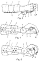
- eine räumliche, teilweise etwas schematische Darstellung der erfindungsgemäßen Handgelenksorthese schräg von oben ohne Gurtbänder,
- Fig. 2 :
- die Handgelenksorthese von
Fig. 1 schräg von unten, - Fig. 3 :
- eine schematische Draufsicht der am Arm eines Patienten angelegten Handgelenksorthese,
- Fig. 4 :
- eine schematische Seitenansicht der Darstellung von
Fig. 3 , wobei sich das Fingerstützelement in einer ersten Winkelstellung befindet und ohne Polsterung dargestellt ist, - Fig. 5 :
- eine schematische Darstellung gemäß
Fig. 4 , wobei das Fingerstützelement in einer zweiten Winkelstellung dargestellt ist, - Fig. 6 :
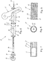
- eine Explosionsdarstellung der Drehlagereinrichtung und des distalen Schienenarms,
- Fig. 7 :
- einen Längsschnitt durch das zweite Lagerteil,
- Fig. 8 :
- eine stirnseitige Ansicht des ersten Lagerteils,
- Fig. 9 :
- einen Längsschnitt durch das erste Lagerteil, und
- Fig. 10 :
- eine Draufsicht auf das am ersten Lagerteil befestigte Handballenstützelement und das am zweiten Lagerteil befestigte Fingerstützelement.
- Im Folgenden wird die Erfindung anhand einer Handgelenksorthese beschrieben, die als dynamische Redressionsorthese ausgebildet ist.
- Wie aus den
Fig. 1 bis 5 ersichtlich, weist die Handgelenksorthese einen proximalen Schienenarm 1 auf, der mittels gepolsterter Halbschalen 2 und nicht dargestellter, an den Halbschalen 2 befestigter Haltegurte seitlich an einem Unterarm 3 befestigt werden kann. - Das distale Ende des proximalen Schienenarms 1 ist mittels eines Drehgelenks 4 gelenkig mit einem distalen Schienenarm 5 verbunden, der sich seitlich neben der Hand 6 erstreckt.
- Mittels des Drehgelenks 4 ist der distale Schienenarm 5 um eine Schwenkachse 7 schwenkbar, die im Bereich des Handgelenks liegt. Das Drehgelenk 4 weist weiterhin üblicherweise Mittel auf, mit denen der mögliche Schwenkbereich des distalen Schienenarms 5 relativ zum proximalen Schienenarm 1 begrenzt und verändert werden kann. Weiterhin weist im Fall einer dynamischen Redressionsorthese das Drehgelenk 4 auch eine Krafterzeugungseinrichtung, insbesondere in der Form einer Spiralfeder, auf, um auf den distalen Schienenarm 5 eine Vorspannkraft aufzubringen, welche den distalen Schienenarm 5 in eine Drehrichtung um die Schwenkachse 7 herum drängt. Ein derartiges Drehgelenk ist beispielsweise in der
EP 0 841 044 A1 näher beschrieben. Im Rahmen der vorliegenden Erfindung ist eine derartige Krafterzeugungseinrichtung jedoch nicht unbedingt erforderlich. - Aus den
Fig. 1 bis 3 ist ersichtlich, dass die Schienenarme 1, 5 und das Drehgelenk 4 auf einer Seite des Unterarms bzw. der Hand angeordnet sind. Im Rahmen der Erfindung ist es jedoch auch möglich, auf beiden Seiten des Unterarms bzw. der Hand Schienenarme 1, 5 und Drehgelenke 4 vorzusehen. - Die Schienenarme 1, 5 sind im Bereich des Drehgelenks 4 mittels eines Polsterkissens 8 zum Handgelenk hin gepolstert.
- Am distalen Schienenarm 5 ist eine Handauflageeinrichtung 9 befestigt, die zum Auflegen der Hand, d.h. des Handballens und der Finger, dient. Die Handauflageeinrichtung 9 umfasst, wie aus den
Fig. 2 und10 ersichtlich, zwei voneinander getrennte, formstabile Handstützelemente, wobei ein Handstützelement als Handballenstützelement 10 zum Stützen des Handballens und das andere Handstützelement als Fingerstützelement 11 zum Stützen des Zeige-, Mittel-, Ring- und kleinen Fingers ausgebildet ist. Zweckmäßigerweise besteht das Fingerstützelement 11 aus einem gebogenen Plattenelement, während es sich beim Handballenstützelement 10 auch um ein zumindest überwiegend ebenes Plattenelement handeln kann. Zweckmäßigerweise bestehen diese Handstützelemente aus stabilen Metallblechen. Das Handballenstützelement 10 bildet zusammen mit dem Fingerstützelement 11 eine weitgehend zusammenhängende Fläche, welche mindestens die Größe der Handfläche hat. - Aus den
Fig. 1 und 2 ist ersichtlich, dass das Handballenstützelement 10 und Fingerstützelement 11 von einer zusammenhängenden Polsterauflage 12 überdeckt sind, die beispielsweise aus Schaumstoff bestehen kann. - Wie aus
Fig. 2 ersichtlich, kann am Handballenstützelement 10 weiterhin ein formstabiles Daumenstützelement 13 zum Aufliegen des Daumens befestigt sind. Ein derartiges Daumenstützelement 13 ist jedoch nicht unbedingt erforderlich. - Die Handauflageeinrichtung 9 ist mittels einer Drehlagereinrichtung 14 verstellbar am distalen Schienenarm 5 befestigt. Die Drehlagereinrichtung 14 ist in
Fig. 6 in Explosionsdarstellung dargestellt und umfasst ein erstes Lagerteil 15, das mittels einer Schraube 16 und einer Unterlegscheibe 17 an der distalen Schiene 5 befestigt werden kann. - Um den Abstand zwischen dem ersten Lagerteil 15 und der Schwenkachse 7 des Drehgelenks 4 variieren zu können, weist der distale Schienenarm 5 ein in seiner Längsrichtung verlaufendes Langloch 18 auf, durch das die Schraube 16 hindurchgeführt wird. Die Schraube 16 ist in eine axiale, zentrale Gewindebohrung 19 (
Fig. 9 ) einschraubbar, die in einem Endbereich des ersten Lagerteils 15 vorgesehen ist. Die distale Schiene 5 erstreckt sich dabei zwischen einer Stirnseite des ersten Lagerteils 15 und der Unterlegscheibe 17 hindurch, so dass nach dem Festziehen der Schraube 16 das erste Lagerteil 15 drehfest und unverschiebbar an der distalen Schiene 5 festgelegt ist. - Das erste Lagerteil 15 weist weiterhin auf einer Seite eine über seine gesamte Länge verlaufende Abflachung 20 auf, die zum Aufsetzen eines Endbereichs des Handballenstützelements 10 dient. Dieser Endbereich des Handballenstützelements 10 wird, wie aus
Fig. 10 ersichtlich, am ersten Lagerteil 15 mittels Schrauben 21 festgeschraubt, die in Schraubenlöcher 22 (Fig. 6 ) des ersten Lagerteils 15 eingeschraubt werden. - In dem zum distalen Schienenarm 5 entfernten Endbereich weist das erste Lagerteil 15 eine zentrale, axiale Gewindebohrung 23 auf. Diese Gewindebohrung 23 dient zum Einschrauben und Verankern einer zentralen Schraube 24, die in axialer Richtung über das erste Lagerteil 15 vorsteht. Weiterhin weist das erste Lagerteil 15 zu seiner Stirnseite hin offene Rastvertiefungen 25 in Form von Löchern auf, die in einem Lochkreis (
Fig. 8 ) eng nebeneinanderliegend und in einem regelmäßigen Winkelabstand um die Mittelachse 26 der Drehlagereinrichtung 14 herum angeordnet sind. Die Rastvertiefungen 25 erstrecken sich von der Stirnseite des ersten Lagerteils 15 in Axialrichtung, d.h. parallel zur Mittelachse 26, ein kleines Stück in das Innere des ersten Lagerteils 15 hinein. - Die Drehlagereinrichtung 14 umfasst ferner ein zweites Lagerteil 27, das hülsen- oder hohlzylinderförmig ausgebildet ist und eine gleiche oder ganz ähnliche Außenkontur wie das erste Lagerteil 15 aufweist. Das zweite Lagerteil 27 dient zum Befestigen des Fingerstützelements 11. Hierzu weist das zweite Lagerteil 27 auf einer Seite eine sich über seine gesamte Länge erstreckende Abflachung 28 auf, auf die ein Endbereich des Fingerstützelements 11 aufgesetzt wird. Dieser Endbereich des Fingerstützelements 11 wird am zweiten Lagerteil 27 mittels Schrauben 29 (
Fig. 10 ) festgeschraubt, die in Schraubenlöcher 30 (Fig. 6 ) des zweiten Lagerteils 27 eingeschraubt werden. - Wie aus
Fig. 7 ersichtlich, weist das zweite Lagerteil 27 eine axial durchgehende, im Durchmesser gestufte Axialbohrung auf. Ein im Durchmesser verringerter Bohrungsabschnitt 31 weist einen Durchmesser auf, der nur geringfügig größer ist als der Durchmesser der Schraube 24, so dass der Schaft der Schraube 24 mit geringem Spiel hindurchgeführt werden kann. Der Bohrungsabschnitt 31 dient als Führungs- oder Lagerabschnitt zur längsverschiebbaren und drehbaren Lagerung des zweiten Lagerteils 27 längs bzw. an der Schraube 24. - An den Bohrungsabschnitt 31 schließt über eine Durchmesserstufe 33 ein im Durchmesser vergrößerter Innenraum 32 an. Im montierten Zustand der Drehlagereinrichtung 14, d.h. wenn das zweite Lagerteil 27 fluchtend zum ersten Lagerteil 15 angeordnet und die zentrale Schraube 24 über den Innenraum 32 und den Bohrungsabschnitt 31 des zweiten Lagerteils 27 hindurch in die Gewindebohrung 23 des ersten Lagerteils 15 eingeschraubt ist, erstreckt sich die zentrale Schraube 24 mit ihrem Schraubenkopf 34 über den Bohrungsabschnitt 31 hinaus ein Stück weit in den Innenraum 32 hinein. Die zentrale Schraube 24 ist hierbei durch eine Feder 35 hindurchgeführt, die im vorliegenden Beispiel als Druckfeder ausgebildet ist und sich mit einem Ende am Schraubenkopf 34 und mit ihrem gegenüberliegenden Ende an der Durchmesserstufe 33 des zweiten Lagerteils 27 abstützt. Die Feder 35 übt auf das zweite Lagerteil 27 eine axial gerichtete Vorspannkraft aus, welche das zweite Lagerteil 27 stirnseitig gegen das erste Lagerteil 15 drückt.
- Wie weiterhin aus
Fig. 6 ersichtlich, sind am zweiten Lagerteil 27 weiterhin zwei Stifte 36 befestigt, die stirnseitig über das zweite Lagerteil 27 vorstehen. Die Stifte 36 weisen zur Mittelachse 26 den gleichen Abstand wie die Rastvertiefungen 25 auf und sind derart ausgebildet, dass sie sich in hierzu fluchtende Rastvertiefungen 25 des ersten Lagerteils 15 hinein erstrecken, wenn die beiden Lagerteile 15, 27 stirnseitig dicht aneinander liegen. Soll das zweite Lagerteil 27 und damit das daran befestigte Fingerstützelement 11 relativ zum ersten Lagerelement 15 und damit zum Handballenstützelement 10 verdreht werden, kann das zweite Lagerteil 27 entgegen der Vorspannkraft der Feder 35 in Axialrichtung vom ersten Lagerteil 15 entfernt und um die zentrale Schraube 24 herum, d.h. um die Mittelachse 26, in die gewünschte Drehwinkelstellung verdreht werden, bis die Stifte 36 mit anderen Rastvertiefungen 25 fluchten. Wird anschließend das zweite Lagerteil 27 losgelassen, wird das zweite Lagerteil 27 durch die Feder 35 wieder an das erste Lagerteil 15 gedrückt, worauf die Stifte 36 in die fluchtenden Rastvertiefungen 25 eingreifen. Die Stifte 36 bilden damit zusammen mit den Rastvertiefungen 25 eine Rasteinrichtung 37, mit welcher das zweite Lagerteil 27 in unterschiedlichen Drehwinkelstellungen am ersten Lagerteil 15 arretiert werden kann. - Auf das zweite Lagerteil 27 ist stirnseitig eine Verschlusskappe 38 aufgesetzt, die fest mit dem zweiten Lagerteil 27 verbunden ist. An der Verschlusskappe 38 ist ein ringförmiges Handhabungsteil 39 befestigt, das mit den Fingern ergriffen werden kann und zum Ziehen des zweiten Lagerteils 27 entgegen der Vorspannkraftfeder 35 dient.
- Es ist ersichtlich, dass durch einfaches Ziehen am Handhabungsteil 39 das zweite Lagerteil 27 zusammen mit dem Fingerstützelement 11 in axialer Richtung vom zweiten Lagerteil 15 entfernt, in gewünschter Weise gedreht und in unterschiedliche Drehwinkelstellungen gebracht werden kann. Wird keine Zugkraft mehr aufgebracht, erfolgt wieder eine automatische Verriegelung des Lagerteils 27 und damit des Fingerstützelements 11 am ersten Lagerteil 15.
- Im Rahmen der Erfindung ist eine Vielzahl von Variationen möglich. Beispielsweise ist es möglich, anstelle der beschriebenen Feder 35 eine andere Krafterzeugungseinrichtung zur Erzeugung einer axialen Vorspannkraft für das zweite Lagerteil 27 vorzusehen, beispielsweise ein elastisches Zugband, das einerseits am zweiten Lagerteil 27 und andererseits am ersten Lagerteil 15 befestigt ist. Die Rasteinrichtung 37 kann ohne weiteres derart modifiziert werden, dass die Stifte 36 nicht am zweiten Lagerteil 27, sondern am ersten Lagerteil 15 befestigt sind, während die Rastvertiefungen 25 am zweiten Lagerteil 27 angeordnet sind. Anstelle von zwei Stiften 36 kann auch eine andere Anzahl von Stiften, beispielsweise lediglich ein Stift, vorgesehen sein. Weiterhin sind anstelle von Stiften 36 auch Zähne denkbar, die in dazu passende Kerben oder Ausnehmungen im gegenüberliegenden Lagerteil eingreifen.
- Obwohl die werkzeuglose Verriegelung des zweiten Lagerteils 27 am ersten Lagerteil 15 mittels der Feder 35 und der Rasteinrichtung 37 besonders vorteilhaft ist, ist es im Rahmen der Erfindung auch möglich, das zweite Lagerteil 27 allein mittels Befestigungsschrauben am ersten Lagerteil 15 zu befestigen, die in einen Lochkreis bildende, unterschiedlich positionierte Schraubenlöcher des ersten Lagerteils 15 einschraubbar sind.
- Das Fingerstützelement 11 kann insbesondere dann, wenn nur ein bis drei Finger gestützt werden müssen, zusammen mit dem Handballenstützelement 10 auch kleiner als die Handfläche ausgebildet sein.
Claims (12)
- Handgelenksorthese mit- einem am Unterarm (3) befestigbaren proximalen Schienenarm (1),- einem distalen Schienenarm (5),- einem Drehgelenk (4) zur gelenkigen Verbindung des distalen Schienenarms (5) mit dem proximalen Schienenarm (1),- einer am distalen Schienenarm (5) befestigten Handauflageeinrichtung (9), die zwei voneinander getrennte, formstabile Handstützelemente aufweist, wobei ein Handstützelement als Handballenstützelement (10) zum Stützen des Handballens und das andere Handstützelement als Fingerstützelement (11) zum Stützen mindestens eines Fingers ausgebildet ist,- wobei die Handauflageeinrichtung (9) eine Drehlagereinrichtung (14) aufweist, mit der die beiden Handstützelemente gelenkig miteinander verbunden sind dadurch gekennzeichnet, dass die Drehlagereinrichtung (14) ein erstes Lagerteil (15), das am distalen Schienenarm (5) befestigt ist und das Handballenstützelement (10) trägt, und ein zweites Lagerteil (27) umfasst, das drehbar am ersten Lagerteil (15) gehaltert ist und das Fingerstützelement (11) trägt,- und wobei die Handauflageeinrichtung (9) eine Arretiereinrichtung zum Arretieren des Fingerstützelementes (11) relativ zum Handballenstützelement (10) in einer bestimmten Drehwinkelstellung aufweist, wobei das zweite Lagerteil (27) der Drehlagereinrichtung (14) mittels der Kraft einer Krafterzeugungseinrichtung in eine Verriegelungsstellung vorgespannt ist, in der das zweite Lagerteil (27) in Druckkontakt mit dem ersten Lagerteil (15) und relativ zum ersten Lagerteil (15) drehverriegelt ist, und dass das zweite Lagerteil (27) entgegen der Vorspannkraft der Krafterzeugungseinrichtung in eine Freigabestellung bewegbar ist, in der das zweite Lagerteil (27) relativ zum ersten Lagerteil (15) drehbar ist.
- Handgelenksorthese nach Anspruch 1, dadurch gekennzeichnet, dass das am distalen Schienenarm (5) befestigte erste Lagerteil (15) das Handballenstützelement (10) trägt.
- Handgelenksorthese nach Anspruch 2, dadurch gekennzeichnet, dass das zweite Lagerteil (27) fluchtend zum ersten Lagerteil (15) angeordnet ist.
- Handgelenksorthese nach Anspruch 2 oder 3, dadurch gekennzeichnet, dass der distale Schienenarm (5) ein sich in seiner Längsrichtung erstreckendes Langloch (18) oder eine Mehrzahl von Bohrungen zur Befestigung des ersten Lagerteils (15) in unterschiedlichen Abständen zum Drehgelenk (4) aufweist.
- Handgelenksorthese nach einem der Ansprüche 2 bis 4, dadurch gekennzeichnet, dass das erste und das zweite Lagerteil (15, 27) zumindest überwiegend zylinderförmig ausgebildet sind.
- Handgelenksorthese nach einem der Ansprüche 2 bis 5, dadurch gekennzeichnet, dass das erste und zweite Lagerteil (15, 27) den gleichen Außendurchmesser aufweisen.
- Handgelenksorthese nach einem der Ansprüche 2 bis 6, dadurch gekennzeichnet, dass die Krafterzeugungseinrichtung aus einer Feder besteht.
- Handgelenksorthese nach einem der Ansprüche 2 bis 7, dadurch gekennzeichnet, dass das zweite Lagerteil (27) längsverschiebbar an einem Führungsstift geführt ist, der am ersten Lagerteil (15) befestigt ist und sich in das zweite Lagerteil (27) hinein erstreckt.
- Handgelenksorthese nach Anspruch 8, dadurch gekennzeichnet, dass der Führungsstift aus einer zentralen Schraube (24) besteht, die in das erste Lagerteil (15) eingeschraubt ist und einen Schraubenkopf (34) aufweist, der einen Anschlag für ein erstes Ende der Feder (35) bildet, während ein zweites Ende der Feder (35) im oder am zweiten Lagerteil (27) abgestützt ist.
- Handgelenksorthese nach Anspruch 9, dadurch gekennzeichnet, dass das zweite Lagerteil (27) hülsenförmig ausgebildet ist und der Schraubenkopf (34) und die Feder (35) im Inneren des zweiten Lagerteils (27) angeordnet sind.
- Handgelenksorthese nach einem der Ansprüche 2 bis 10, dadurch gekennzeichnet, dass die Arretiereinrichtung eine Rasteinrichtung (37) umfasst, die mindestens einen Stift (36) oder Zahn aufweist, der am ersten oder zweiten Lagerteil (15, 27) angeordnet ist und in unterschiedlich positionierte Rastvertiefungen (25) eingeführt werden kann, die am gegenüberliegenden Lagerteil (15, 27) angeordnet sind.
- Handgelenksorthese nach Anspruch11, dadurch gekennzeichnet, dass die Rastvertiefungen (25) in Umfangsrichtung des ersten oder zweiten Lagerteils (15, 27) in einem regelmäßigen Winkelabstand angeordnet sind.
Applications Claiming Priority (1)
| Application Number | Priority Date | Filing Date | Title |
|---|---|---|---|
| DE102015012320.3A DE102015012320B4 (de) | 2015-09-23 | 2015-09-23 | Handgelenksorthese |
Publications (2)
| Publication Number | Publication Date |
|---|---|
| EP3146944A1 EP3146944A1 (de) | 2017-03-29 |
| EP3146944B1 true EP3146944B1 (de) | 2019-03-13 |
Family
ID=56990272
Family Applications (1)
| Application Number | Title | Priority Date | Filing Date |
|---|---|---|---|
| EP16189941.4A Active EP3146944B1 (de) | 2015-09-23 | 2016-09-21 | Handgelenksorthese |
Country Status (2)
| Country | Link |
|---|---|
| EP (1) | EP3146944B1 (de) |
| DE (1) | DE102015012320B4 (de) |
Families Citing this family (1)
| Publication number | Priority date | Publication date | Assignee | Title |
|---|---|---|---|---|
| DE102017127892A1 (de) * | 2017-11-24 | 2019-05-29 | Ottobock Se & Co. Kgaa | Handorthese und System mit einer Handorthese |
Family Cites Families (6)
| Publication number | Priority date | Publication date | Assignee | Title |
|---|---|---|---|---|
| US3631542A (en) * | 1969-08-11 | 1972-01-04 | Univ Iowa State Res Found | Myoelectric brace |
| GR1001263B (el) * | 1992-08-25 | 1993-06-30 | Vasileios Ladopoulos | Οργανο συνεχους μηχανικης διατασης δια τις αρθρωσεις της ακρας χειρας. |
| DE19637728A1 (de) * | 1996-09-16 | 1998-03-26 | Bauerfeind Gmbh | Kniegelenkorthese |
| DE19645076A1 (de) | 1996-10-31 | 1998-05-14 | Albrecht Gmbh | Vorrichtung zur Reduktion von Streck- oder Beugedefiziten eines distalen Körperglieds gegenüber einem proximalen Körperglied |
| DE10207702C1 (de) * | 2002-02-22 | 2003-08-28 | Albrecht Gmbh | Einstellbare Gelenkorthese |
| DE202004005876U1 (de) * | 2004-04-14 | 2004-09-09 | Lee, Chin-Tsun, Yung Kang | Handschiene |
-
2015
- 2015-09-23 DE DE102015012320.3A patent/DE102015012320B4/de active Active
-
2016
- 2016-09-21 EP EP16189941.4A patent/EP3146944B1/de active Active
Non-Patent Citations (1)
| Title |
|---|
| None * |
Also Published As
| Publication number | Publication date |
|---|---|
| DE102015012320B4 (de) | 2017-04-20 |
| DE102015012320A1 (de) | 2017-03-23 |
| EP3146944A1 (de) | 2017-03-29 |
Similar Documents
| Publication | Publication Date | Title |
|---|---|---|
| EP1482881B1 (de) | Orthese mit einstellbarem bewegungsbereich | |
| EP1575464B1 (de) | Vorrichtung zum aufbringen einer ventral oder dorsal gerichteten translationskraft im kniegelenksbereich | |
| DE112012004113B4 (de) | Orthese zur Korrektur von Oberarmfrakturen | |
| DE112014001466T5 (de) | Flexibler Arm und Verfahren zu dessen Verwendung | |
| EP1568337A1 (de) | Orthese zur Korrektur der Stellung eines Körpergelenks | |
| EP0841044A1 (de) | Dynamische Gelenkstütze | |
| EP1121077A1 (de) | Orthesengelenk | |
| EP3037075A2 (de) | Orthese mit inklinationsverstelleinrichtung | |
| EP3352713B1 (de) | Dynamische gelenkstütze | |
| WO2023025354A1 (de) | Einstellbares orthesengelenk zur kontrollierten bewegung und/oder fixierung einer hand sowie orthese mit einem derartigen orthesengelenk | |
| EP3536298B1 (de) | Massagevorrichtung | |
| DE602004000583T3 (de) | Gelenkverbindung für eine postoperative Orthese | |
| EP2444037B1 (de) | Dynamische Schultergelenksorthese, insbesondere Schulterabduktionsorthese | |
| EP3146944B1 (de) | Handgelenksorthese | |
| EP3669833B1 (de) | Dynamisches orthesengelenk | |
| DE102015005572B4 (de) | Knieorthese zum Aufbringen einer ventral oder dorsal gerichteten Translationskraft | |
| WO2018028891A1 (de) | Gelenk für eine orthopädische einrichtung | |
| EP0303773A3 (de) | Stützvorrichtung für die Wirbel der menschlichen Wirbelsäule | |
| EP3651703A1 (de) | Verbindungseinrichtung und gelenkeinrichtung für eine orthopädietechnische einrichtung | |
| EP3858302B1 (de) | Gelenk für eine orthopädische quengelschiene | |
| DE69737893T2 (de) | Vorrichtung zur physikalischen therapie der schulter | |
| DE2133440C2 (de) | Gelenkstützvorrichtung | |
| DE202020005479U1 (de) | Orthopädische Orthese zum Durchführen von Pronosupinationsübungen mit einstellbarem Bewegungsbereich | |
| EP3275600A1 (de) | Bolzenschneider | |
| DE4445020A1 (de) | Gelenkschiene mit Vorbringerfunktion |
Legal Events
| Date | Code | Title | Description |
|---|---|---|---|
| PUAI | Public reference made under article 153(3) epc to a published international application that has entered the european phase |
Free format text: ORIGINAL CODE: 0009012 |
|
| STAA | Information on the status of an ep patent application or granted ep patent |
Free format text: STATUS: THE APPLICATION HAS BEEN PUBLISHED |
|
| AK | Designated contracting states |
Kind code of ref document: A1 Designated state(s): AL AT BE BG CH CY CZ DE DK EE ES FI FR GB GR HR HU IE IS IT LI LT LU LV MC MK MT NL NO PL PT RO RS SE SI SK SM TR |
|
| AX | Request for extension of the european patent |
Extension state: BA ME |
|
| STAA | Information on the status of an ep patent application or granted ep patent |
Free format text: STATUS: REQUEST FOR EXAMINATION WAS MADE |
|
| 17P | Request for examination filed |
Effective date: 20170907 |
|
| RBV | Designated contracting states (corrected) |
Designated state(s): AL AT BE BG CH CY CZ DE DK EE ES FI FR GB GR HR HU IE IS IT LI LT LU LV MC MK MT NL NO PL PT RO RS SE SI SK SM TR |
|
| GRAP | Despatch of communication of intention to grant a patent |
Free format text: ORIGINAL CODE: EPIDOSNIGR1 |
|
| STAA | Information on the status of an ep patent application or granted ep patent |
Free format text: STATUS: GRANT OF PATENT IS INTENDED |
|
| INTG | Intention to grant announced |
Effective date: 20181009 |
|
| GRAS | Grant fee paid |
Free format text: ORIGINAL CODE: EPIDOSNIGR3 |
|
| GRAA | (expected) grant |
Free format text: ORIGINAL CODE: 0009210 |
|
| STAA | Information on the status of an ep patent application or granted ep patent |
Free format text: STATUS: THE PATENT HAS BEEN GRANTED |
|
| AK | Designated contracting states |
Kind code of ref document: B1 Designated state(s): AL AT BE BG CH CY CZ DE DK EE ES FI FR GB GR HR HU IE IS IT LI LT LU LV MC MK MT NL NO PL PT RO RS SE SI SK SM TR |
|
| REG | Reference to a national code |
Ref country code: GB Ref legal event code: FG4D Free format text: NOT ENGLISH |
|
| REG | Reference to a national code |
Ref country code: CH Ref legal event code: EP Ref country code: AT Ref legal event code: REF Ref document number: 1106677 Country of ref document: AT Kind code of ref document: T Effective date: 20190315 |
|
| REG | Reference to a national code |
Ref country code: IE Ref legal event code: FG4D Free format text: LANGUAGE OF EP DOCUMENT: GERMAN |
|
| REG | Reference to a national code |
Ref country code: DE Ref legal event code: R096 Ref document number: 502016003699 Country of ref document: DE |
|
| REG | Reference to a national code |
Ref country code: NL Ref legal event code: MP Effective date: 20190313 |
|
| REG | Reference to a national code |
Ref country code: LT Ref legal event code: MG4D |
|
| PG25 | Lapsed in a contracting state [announced via postgrant information from national office to epo] |
Ref country code: SE Free format text: LAPSE BECAUSE OF FAILURE TO SUBMIT A TRANSLATION OF THE DESCRIPTION OR TO PAY THE FEE WITHIN THE PRESCRIBED TIME-LIMIT Effective date: 20190313 Ref country code: LT Free format text: LAPSE BECAUSE OF FAILURE TO SUBMIT A TRANSLATION OF THE DESCRIPTION OR TO PAY THE FEE WITHIN THE PRESCRIBED TIME-LIMIT Effective date: 20190313 Ref country code: FI Free format text: LAPSE BECAUSE OF FAILURE TO SUBMIT A TRANSLATION OF THE DESCRIPTION OR TO PAY THE FEE WITHIN THE PRESCRIBED TIME-LIMIT Effective date: 20190313 Ref country code: NO Free format text: LAPSE BECAUSE OF FAILURE TO SUBMIT A TRANSLATION OF THE DESCRIPTION OR TO PAY THE FEE WITHIN THE PRESCRIBED TIME-LIMIT Effective date: 20190613 |
|
| PG25 | Lapsed in a contracting state [announced via postgrant information from national office to epo] |
Ref country code: BG Free format text: LAPSE BECAUSE OF FAILURE TO SUBMIT A TRANSLATION OF THE DESCRIPTION OR TO PAY THE FEE WITHIN THE PRESCRIBED TIME-LIMIT Effective date: 20190613 Ref country code: HR Free format text: LAPSE BECAUSE OF FAILURE TO SUBMIT A TRANSLATION OF THE DESCRIPTION OR TO PAY THE FEE WITHIN THE PRESCRIBED TIME-LIMIT Effective date: 20190313 Ref country code: GR Free format text: LAPSE BECAUSE OF FAILURE TO SUBMIT A TRANSLATION OF THE DESCRIPTION OR TO PAY THE FEE WITHIN THE PRESCRIBED TIME-LIMIT Effective date: 20190614 Ref country code: NL Free format text: LAPSE BECAUSE OF FAILURE TO SUBMIT A TRANSLATION OF THE DESCRIPTION OR TO PAY THE FEE WITHIN THE PRESCRIBED TIME-LIMIT Effective date: 20190313 Ref country code: LV Free format text: LAPSE BECAUSE OF FAILURE TO SUBMIT A TRANSLATION OF THE DESCRIPTION OR TO PAY THE FEE WITHIN THE PRESCRIBED TIME-LIMIT Effective date: 20190313 Ref country code: RS Free format text: LAPSE BECAUSE OF FAILURE TO SUBMIT A TRANSLATION OF THE DESCRIPTION OR TO PAY THE FEE WITHIN THE PRESCRIBED TIME-LIMIT Effective date: 20190313 |
|
| PG25 | Lapsed in a contracting state [announced via postgrant information from national office to epo] |
Ref country code: IT Free format text: LAPSE BECAUSE OF FAILURE TO SUBMIT A TRANSLATION OF THE DESCRIPTION OR TO PAY THE FEE WITHIN THE PRESCRIBED TIME-LIMIT Effective date: 20190313 Ref country code: RO Free format text: LAPSE BECAUSE OF FAILURE TO SUBMIT A TRANSLATION OF THE DESCRIPTION OR TO PAY THE FEE WITHIN THE PRESCRIBED TIME-LIMIT Effective date: 20190313 Ref country code: CZ Free format text: LAPSE BECAUSE OF FAILURE TO SUBMIT A TRANSLATION OF THE DESCRIPTION OR TO PAY THE FEE WITHIN THE PRESCRIBED TIME-LIMIT Effective date: 20190313 Ref country code: ES Free format text: LAPSE BECAUSE OF FAILURE TO SUBMIT A TRANSLATION OF THE DESCRIPTION OR TO PAY THE FEE WITHIN THE PRESCRIBED TIME-LIMIT Effective date: 20190313 Ref country code: EE Free format text: LAPSE BECAUSE OF FAILURE TO SUBMIT A TRANSLATION OF THE DESCRIPTION OR TO PAY THE FEE WITHIN THE PRESCRIBED TIME-LIMIT Effective date: 20190313 Ref country code: SK Free format text: LAPSE BECAUSE OF FAILURE TO SUBMIT A TRANSLATION OF THE DESCRIPTION OR TO PAY THE FEE WITHIN THE PRESCRIBED TIME-LIMIT Effective date: 20190313 Ref country code: PT Free format text: LAPSE BECAUSE OF FAILURE TO SUBMIT A TRANSLATION OF THE DESCRIPTION OR TO PAY THE FEE WITHIN THE PRESCRIBED TIME-LIMIT Effective date: 20190713 Ref country code: AL Free format text: LAPSE BECAUSE OF FAILURE TO SUBMIT A TRANSLATION OF THE DESCRIPTION OR TO PAY THE FEE WITHIN THE PRESCRIBED TIME-LIMIT Effective date: 20190313 |
|
| PG25 | Lapsed in a contracting state [announced via postgrant information from national office to epo] |
Ref country code: PL Free format text: LAPSE BECAUSE OF FAILURE TO SUBMIT A TRANSLATION OF THE DESCRIPTION OR TO PAY THE FEE WITHIN THE PRESCRIBED TIME-LIMIT Effective date: 20190313 Ref country code: SM Free format text: LAPSE BECAUSE OF FAILURE TO SUBMIT A TRANSLATION OF THE DESCRIPTION OR TO PAY THE FEE WITHIN THE PRESCRIBED TIME-LIMIT Effective date: 20190313 |
|
| REG | Reference to a national code |
Ref country code: DE Ref legal event code: R097 Ref document number: 502016003699 Country of ref document: DE |
|
| PG25 | Lapsed in a contracting state [announced via postgrant information from national office to epo] |
Ref country code: IS Free format text: LAPSE BECAUSE OF FAILURE TO SUBMIT A TRANSLATION OF THE DESCRIPTION OR TO PAY THE FEE WITHIN THE PRESCRIBED TIME-LIMIT Effective date: 20190713 |
|
| PLBE | No opposition filed within time limit |
Free format text: ORIGINAL CODE: 0009261 |
|
| STAA | Information on the status of an ep patent application or granted ep patent |
Free format text: STATUS: NO OPPOSITION FILED WITHIN TIME LIMIT |
|
| PG25 | Lapsed in a contracting state [announced via postgrant information from national office to epo] |
Ref country code: DK Free format text: LAPSE BECAUSE OF FAILURE TO SUBMIT A TRANSLATION OF THE DESCRIPTION OR TO PAY THE FEE WITHIN THE PRESCRIBED TIME-LIMIT Effective date: 20190313 |
|
| 26N | No opposition filed |
Effective date: 20191216 |
|
| PG25 | Lapsed in a contracting state [announced via postgrant information from national office to epo] |
Ref country code: SI Free format text: LAPSE BECAUSE OF FAILURE TO SUBMIT A TRANSLATION OF THE DESCRIPTION OR TO PAY THE FEE WITHIN THE PRESCRIBED TIME-LIMIT Effective date: 20190313 |
|
| PG25 | Lapsed in a contracting state [announced via postgrant information from national office to epo] |
Ref country code: TR Free format text: LAPSE BECAUSE OF FAILURE TO SUBMIT A TRANSLATION OF THE DESCRIPTION OR TO PAY THE FEE WITHIN THE PRESCRIBED TIME-LIMIT Effective date: 20190313 |
|
| PG25 | Lapsed in a contracting state [announced via postgrant information from national office to epo] |
Ref country code: MC Free format text: LAPSE BECAUSE OF FAILURE TO SUBMIT A TRANSLATION OF THE DESCRIPTION OR TO PAY THE FEE WITHIN THE PRESCRIBED TIME-LIMIT Effective date: 20190313 |
|
| REG | Reference to a national code |
Ref country code: CH Ref legal event code: PL |
|
| PG25 | Lapsed in a contracting state [announced via postgrant information from national office to epo] |
Ref country code: LI Free format text: LAPSE BECAUSE OF NON-PAYMENT OF DUE FEES Effective date: 20190930 Ref country code: LU Free format text: LAPSE BECAUSE OF NON-PAYMENT OF DUE FEES Effective date: 20190921 Ref country code: IE Free format text: LAPSE BECAUSE OF NON-PAYMENT OF DUE FEES Effective date: 20190921 Ref country code: CH Free format text: LAPSE BECAUSE OF NON-PAYMENT OF DUE FEES Effective date: 20190930 |
|
| REG | Reference to a national code |
Ref country code: BE Ref legal event code: MM Effective date: 20190930 |
|
| PG25 | Lapsed in a contracting state [announced via postgrant information from national office to epo] |
Ref country code: BE Free format text: LAPSE BECAUSE OF NON-PAYMENT OF DUE FEES Effective date: 20190930 |
|
| PG25 | Lapsed in a contracting state [announced via postgrant information from national office to epo] |
Ref country code: CY Free format text: LAPSE BECAUSE OF FAILURE TO SUBMIT A TRANSLATION OF THE DESCRIPTION OR TO PAY THE FEE WITHIN THE PRESCRIBED TIME-LIMIT Effective date: 20190313 |
|
| PG25 | Lapsed in a contracting state [announced via postgrant information from national office to epo] |
Ref country code: HU Free format text: LAPSE BECAUSE OF FAILURE TO SUBMIT A TRANSLATION OF THE DESCRIPTION OR TO PAY THE FEE WITHIN THE PRESCRIBED TIME-LIMIT; INVALID AB INITIO Effective date: 20160921 Ref country code: MT Free format text: LAPSE BECAUSE OF FAILURE TO SUBMIT A TRANSLATION OF THE DESCRIPTION OR TO PAY THE FEE WITHIN THE PRESCRIBED TIME-LIMIT Effective date: 20190313 |
|
| PG25 | Lapsed in a contracting state [announced via postgrant information from national office to epo] |
Ref country code: MK Free format text: LAPSE BECAUSE OF FAILURE TO SUBMIT A TRANSLATION OF THE DESCRIPTION OR TO PAY THE FEE WITHIN THE PRESCRIBED TIME-LIMIT Effective date: 20190313 |
|
| REG | Reference to a national code |
Ref country code: AT Ref legal event code: MM01 Ref document number: 1106677 Country of ref document: AT Kind code of ref document: T Effective date: 20210921 |
|
| PG25 | Lapsed in a contracting state [announced via postgrant information from national office to epo] |
Ref country code: AT Free format text: LAPSE BECAUSE OF NON-PAYMENT OF DUE FEES Effective date: 20210921 |
|
| P01 | Opt-out of the competence of the unified patent court (upc) registered |
Effective date: 20230524 |
|
| PGFP | Annual fee paid to national office [announced via postgrant information from national office to epo] |
Ref country code: GB Payment date: 20230921 Year of fee payment: 8 |
|
| PGFP | Annual fee paid to national office [announced via postgrant information from national office to epo] |
Ref country code: FR Payment date: 20230918 Year of fee payment: 8 Ref country code: DE Payment date: 20230919 Year of fee payment: 8 |