EP3146868B1 - Multifunktionsmöbel - Google Patents
Multifunktionsmöbel Download PDFInfo
- Publication number
- EP3146868B1 EP3146868B1 EP16189672.5A EP16189672A EP3146868B1 EP 3146868 B1 EP3146868 B1 EP 3146868B1 EP 16189672 A EP16189672 A EP 16189672A EP 3146868 B1 EP3146868 B1 EP 3146868B1
- Authority
- EP
- European Patent Office
- Prior art keywords
- back part
- furniture
- seat
- seat part
- accordance
- Prior art date
- Legal status (The legal status is an assumption and is not a legal conclusion. Google has not performed a legal analysis and makes no representation as to the accuracy of the status listed.)
- Active
Links
- 238000000034 method Methods 0.000 claims description 4
- 238000006073 displacement reaction Methods 0.000 claims description 3
- 238000000465 moulding Methods 0.000 description 3
- 230000001419 dependent effect Effects 0.000 description 1
- 238000011161 development Methods 0.000 description 1
- 230000018109 developmental process Effects 0.000 description 1
- 230000005284 excitation Effects 0.000 description 1
- 230000003287 optical effect Effects 0.000 description 1
- 230000000284 resting effect Effects 0.000 description 1
Images

Classifications
-
- A—HUMAN NECESSITIES
- A47—FURNITURE; DOMESTIC ARTICLES OR APPLIANCES; COFFEE MILLS; SPICE MILLS; SUCTION CLEANERS IN GENERAL
- A47C—CHAIRS; SOFAS; BEDS
- A47C17/00—Sofas; Couches; Beds
- A47C17/04—Seating furniture, e.g. sofas, couches, settees, or the like, with movable parts changeable to beds; Chair beds
- A47C17/16—Seating furniture changeable to beds by tilting or pivoting the back-rest
- A47C17/163—Seating furniture changeable to beds by tilting or pivoting the back-rest and a foot-rest
-
- A—HUMAN NECESSITIES
- A47—FURNITURE; DOMESTIC ARTICLES OR APPLIANCES; COFFEE MILLS; SPICE MILLS; SUCTION CLEANERS IN GENERAL
- A47C—CHAIRS; SOFAS; BEDS
- A47C17/00—Sofas; Couches; Beds
- A47C17/04—Seating furniture, e.g. sofas, couches, settees, or the like, with movable parts changeable to beds; Chair beds
- A47C17/16—Seating furniture changeable to beds by tilting or pivoting the back-rest
- A47C17/17—Seating furniture changeable to beds by tilting or pivoting the back-rest with coupled movement of back-rest and seat
Definitions
- the invention relates to a multifunctional furniture, in particular chaise lounge or chaise longue, which is adjustable between a sitting position and a reclining position, comprising a base and a foot part, a seat part and a back part, which are attached to the base.
- a multifunctional furniture according to the preamble of claim 1 is in essence, for example, from DE 103 17 225 A1 known.
- a similar multifunctional furniture also describes the US 4 183 109 A ,
- Such furniture is thus basically known.
- the back part can not be adjusted to a horizontal lying position. If such an adjustment is possible, individual moldings, for example upholstery of the seat part or the back part, are undesirably compressed. On the one hand, this is disadvantageous for optical reasons. On the other hand, this also leads to increased wear and wear of the moldings.
- an adjusting movement of the back part comprises a combined rotary and sliding movement.
- a fitting which comprises a slotted guide for the back part, wherein the slotted guide is pivotally mounted.
- a groove or a slot of the slotted guide may in particular be arcuate, so that the back part can perform an arcuate sliding movement.
- a sliding block of the back part engages in the slotted guide.
- the back part is forcibly coupled in this way with the slotted guide.
- the back part can be rotatably mounted on the slide guide.
- the positively coupled with the slotted guide back part can also be pivoted by pivoting the slotted guide.
- the slide guide and the back part when adjusting in the same direction are pivotable, while the back part is also displaced along the slotted guide relative to this.
- the multifunctional furniture may in particular be a sofa or couch part, preferably a chaise longue or chaise longue, or another piece of furniture which is designed for sitting and / or lying and in particular has a padding.
- the foot part is oriented horizontally.
- a user sits with his upper body upright while his legs are resting on the footboard and not touching the ground.
- a sitting position is to be understood both a position in which the back part extends substantially vertically or only slightly inclined backwards, as well as a relaxation position in which the back part is further inclined backwards.
- a head part may be provided.
- the head part can be moved independently in any position of the back part.
- a head motor for adjusting the head part may be provided.
- the head motor can be arranged on the head part itself.
- the back part in particular on the back, have a head motor for the head part.
- the head motor can be connected by a fitting with the head part, preferably via parallel lever.
- the back part is displaced forward when adjusting the back part in the lying position.
- the back part can thus move away from a wall when adjusting.
- Such furniture is also referred to as "wall-free”. The furniture can thus be adjusted even if it is placed directly or close to a wall.
- the foot part and / or the seat part are displaceable relative to the base. In this way, space is created for the back part.
- the back part can therefore be adjusted to the front and needs to the rear, so for example on the side facing a wall, no additional space when adjusting.
- At least one roller guide and / or a motor are provided for the displacement movement of the foot part and / or the seat part.
- separate roller guides can be provided in each case.
- the roller guide for the foot can be oriented horizontally.
- the roller can be attached to the foot part or to the base.
- the roller guide for a rear portion of the seat portion may be inclined.
- the seat part can be raised by the roller guide, for example, obliquely forward.
- a further roller guide may be provided for a front region of the seat part.
- the path of this roller guide may be formed in particular arcuate.
- the seat part may have a seat motor.
- the seat motor can hereby slide the seat part obliquely upwards. This also pushes the foot part forward.
- the seat motor may include a piston / cylinder arrangement or a spindle drive. By means of the seat motor, an actuator acting on the seat part can be changed in length, in order to move the seat part in this way. Alternatively, a manual adjustability can be provided.
- the back part in the reclining position is adjustable by a sliding movement of the foot part and / or the seat part away from the back.
- the back part can thus be forcibly coupled in particular with the foot part and / or seat part.
- An optionally provided seat motor can preferably entrain the back part when adjusting the seat part, either indirectly via the seat part or by a direct connection to the back part.
- the seat part is inclined in the sitting position in the direction of the back part downwards.
- a rear region of the seat part during the adjustment of the back part in the lying position can be raised. In this way, in the sitting position in the direction of back part downwardly inclined seat part can be brought into a horizontal position.
- the fitting comprises a pivot arm which connects the base to the back part.
- the back part can thus be held by the swivel arm and the slotted guide.
- the sliding guide is in each case hingedly connected to the seat part and the pivot arm.
- the slide guide can attack approximately centrally on the swivel arm.
- the slotted guide can be pivoted by the articulated connections. In particular, it can be achieved that during pivoting due to the connection between link guide and swivel arm and the swivel arm is always moved.
- an excitation movement e.g. a displacement of the seat part and / or foot part
- a motor in particular a seat motor
- the sliding part attached to the seat part can be pulled along.
- the seat part and / or the foot can be moved on rollers forward or obliquely upwards.
- the slide guide is in particular hingedly connected to the pivot arm and can therefore tilt the pivot arm forward.
- the swivel arm in turn pivots about its fixed point with the base and pushes the back part, with which the swivel arm is also connected, forward.
- the movement of the back part is further determined by the slotted guide, with which the back part cooperates. Thereby, the back part can be pivoted from a substantially upright sitting position in the horizontal reclining position and simultaneously pushed forward.
- the invention also relates to a method for adjusting a multifunctional furniture between a sitting position and a reclining position, in which a seat part is moved forward from the sitting position into the reclining position, the seat part entrains a slotted guide, the slotted guide thereby pivots a swivel arm, and the swivel arm thereby a forced on the slide guide forced back part in the lying position.
- the illustrated embodiments are merely exemplary in nature. Furthermore, it is provided in particular that some of the illustrated and described components are provided in pairs in the form of a left component and a right component, wherein in each case the two components of a pair are preferably coupled together so that they can only be moved together.
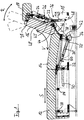
- Fig. 1 shows a multifunctional furniture, which is designed as a Recamiere, in a sitting position.
- the furniture comprises a base 10 standing on the floor, a foot part 12, a seat part 14, a back part 16 and a head part 18.
- the foot part 12, the seat part 14 and the back part 16 are each attached to the base 10 and adjustable relative thereto.
- the head part 18 is connected via a rotary joint 20 to the back part 16 and can be adjusted by means of a head motor 22 by a head fitting 24, which comprises a parallel lever 26, in dashed lines positions and thereby perform a pivoting movement R.
- the head motor 22 and the head fitting 24 are arranged on the rear side of the back part 16.
- the head part 18 can be adjusted independently of the adjustment of the back part 16.
- the adjustment of the formed to a sliding movement S foot part 12 is facilitated by provided on the base 10 and the foot 12 rollers 28.
- the foot 12 can be pulled forward and pushed back again.
- the seat part 14 can be moved. In the sitting position, the seat part 14 is inclined in the direction of the back part 16 downward. To move the seat part 14, two roller guides 30, 30 'are provided in the base 10 (shown in dashed lines). These are designed as slide guides for rollers 32, 32 'of the seat part 14.
- the one roller guide 30 is in this case arcuate, while the other roller guide 30 'extending straight from the bottom rear obliquely forward above. Thereby, the seat part 14 is raised in the rear area, while it is pushed forward.
- the sliding movement of the seat portion 14 is effected by a seat motor 34 which is actuated by a variable length actuator 50, e.g. in the form of a spindle drive with a front lower portion of the seat part 14 cooperates.
- a seat motor 34 which is actuated by a variable length actuator 50, e.g. in the form of a spindle drive with a front lower portion of the seat part 14 cooperates.
- the seat part 14 In a lying position, which in Fig. 2 is shown, the seat part 14 is thus in a horizontal position. The seat part 14 and the foot part 12 are pushed forward in this lying position, so that enough space for the back part 16 is available. No space is needed behind the furniture in this way. The furniture can therefore also stand directly on a wall.
- a fitting 36 For adjusting the back part 16, a fitting 36 is provided.
- the fitting 36 includes a slotted guide 38 and a pivot arm 40.
- the slotted guide 38 is connected on the one hand via a hinge 42 with the seat part 14.
- the slotted guide 38 is attached via a joint 42 'approximately centrally on the pivot arm 40.
- a sliding block 44 of the back part 16 engages in an arcuate groove 46 of the slotted guide 38.
- the back part 16 is also rotatably mounted on the slotted guide 38.
- the pivot arm 40 is connected to the base 10 at an end portion via a hinge 48. At the other end region of the pivot arm 40 is connected via a hinge 48 'to the back part 16. The back part 16 is thus held on the one hand by the pivot arm 40 and on the other hand by the sliding guide 38 due to the selected geometry safely in the sitting position.
- the seat part 14 and the foot part 12 are pushed forward by means of the seat motor 34, the rollers 28, 32, 32 'and the roller guides 30, 30' moving in the sliding direction S facilitate.
- the rear portion of the seat part 14 is thereby raised. Since the slide guide 38 is connected to the seat part 14, the slide guide 38 is pulled forward.
- the slide guide 38 is in turn connected to the pivot arm 40 so that it tilts forward.
- the pivot arm 40 By the pivot arm 40 while the back part 16 is pushed forward and pivoted, in the sense of an increasingly lower inclination of a leaning surface of the back part 16, ie in the Fig. 1 and 2 clockwise.
- the back part 16 is forcibly guided on the sliding guide 38.
- the foot part 12 In the lying position, ie in the extended state, the foot part 12, the seat part 14 and the back part 16 form a flat lying surface.
- the head part 18 can be adjusted as desired by the head motor 22.
Description
- Die Erfindung betrifft ein Multifunktionsmöbel, insbesondere Recamiere oder Chaiselongue, welches zwischen einer Sitzstellung und einer Liegestellung verstellbar ist, umfassend eine Basis sowie ein Fußteil, ein Sitzteil und ein Rückenteil, die an der Basis angebracht sind. Ein derartiges Multifunktionsmöbel gemäß dem Oberbegriff des Anspruchs 1 ist dem Wesen nach beispielsweise aus der
DE 103 17 225 A1 bekannt. Ein ähnliches Multifunktionsmöbel beschreibt ferner dieUS 4 183 109 A . - Derartige Möbel sind somit grundsätzlich bekannt. Jedoch kann häufig das Rückenteil nicht zu einer horizontalen Liegestellung verstellt werden. Ist eine solche Verstellung zwar möglich, so werden dabei einzelne Formteile, beispielsweise Polsterungen des Sitzteils oder des Rückenteils, jedoch in unerwünschter Weise zusammengedrückt. Dies ist einerseits bereits aus optischen Gründen von Nachteil. Andererseits führt dies auch zu einem erhöhten Verschleiß und zu Abnutzungen der Formteile.
- Es ist daher eine Aufgabe der Erfindung, ein Multifunktionsmöbel der eingangs genannten Art dahingehend zu verbessern, dass das Rückenteil auf einfache Weise in eine horizontale Liegestellung verstellt werden kann, ohne einzelne Formteile dabei unnötigen Belastungen auszusetzen.
- Die Lösung dieser Aufgabe erfolgt durch ein Möbel mit den Merkmalen des Anspruchs 1 sowie durch ein Verstellverfahren mit den Merkmalen des Anspruchs 8. Erfindungsgemäß umfasst eine Verstellbewegung des Rückenteils eine kombinierte Dreh- und Schiebebewegung. Durch eine solche kombinierte Verstellbewegung kann erreicht werden, dass das Rückenteil in der Liegestellung bei auf dem Boden stehender Basis zumindest im Wesentlichen horizontal ausgerichtet ist.
- Erfindungsgemäß ist ein Beschlag vorgesehen, welcher eine Kulissenführung für das Rückenteil umfasst, wobei die Kulissenführung schwenkbar gelagert ist. Eine Nut oder ein Langloch der Kulissenführung kann insbesondere bogenförmig ausgebildet sein, so dass auch das Rückenteil eine bogenförmige Verschiebebewegung vollziehen kann. Vorzugsweise greift ein Kulissenstein des Rückenteils in die Kulissenführung ein. Das Rückenteil ist auf diese Weise mit der Kulissenführung zwangsgekoppelt. Insbesondere kann das Rückenteil dabei drehbar an der Kulissenführung gelagert sein.
- Das mit der Kulissenführung zwangsgekoppelte Rückenteil kann durch Verschwenken der Kulissenführung ebenfalls verschwenkt werden. Insbesondere sind die Kulissenführung und das Rückenteil beim Verstellen gleichsinnig verschwenkbar, während das Rückenteil zusätzlich längs der Kulissenführung relativ zu dieser verschoben wird.
- Bei dem Multifunktionsmöbel kann es sich insbesondere um ein Sofa bzw. Couchteil, vorzugsweise Recamiere oder Chaiselongue, oder ein anderes Möbel handeln, welches zum Sitzen und/oder Liegen ausgebildet ist und insbesondere eine Polsterung aufweist.
- Vorzugsweise ist auch in der Sitzstellung das Fußteil horizontal orientiert. So sitzt ein Benutzer mit dem Oberkörper aufrecht, während seine Beine ausgestreckt auf dem Fußteil ruhen und nicht den Boden berühren.
- Unter einer Sitzstellung ist sowohl eine Stellung zu verstehen, bei der sich das Rückenteil im Wesentlichen vertikal erstreckt oder nur leicht nach hinten geneigt ist, als auch eine Relaxstellung, bei der das Rückenteil weiter nach hinten geneigt ist.
- Vorzugsweise kann ein Kopfteil vorgesehen sein. Das Kopfteil kann insbesondere unabhängig in jeder Position des Rückenteils bewegbar sein. Zum Verstellen des Kopfteils kann ein Kopfmotor vorgesehen sein. Der Kopfmotor kann am Kopfteil selbst angeordnet sein. Alternativ kann das Rückenteil, insbesondere auf der Rückseite, einen Kopfmotor für das Kopfteil aufweisen. Der Kopfmotor kann durch einen Beschlag mit dem Kopfteil verbunden sein, vorzugsweise über Parallelhebel.
- Insbesondere ist beim Verstellen des Rückenteils in die Liegestellung das Rückenteil nach vorne verschiebbar. Das Rückenteil kann sich somit beim Verstellen von einer Wand wegbewegen. Ein solches Möbel wird auch als "wandfrei" bezeichnet. Das Möbel kann folglich auch dann verstellt werden, wenn es unmittelbar oder nahe an einer Wand platziert ist.
- Durch die kombinierte Dreh- und Schiebebewegung wird ein schonender Verstellmechanismus ermöglicht, bei dem Formteile nicht "gequetscht" werden.
- Weiterbildungen der Erfindung sind auch den abhängigen Ansprüchen, der Beschreibung sowie den beigefügten Zeichnungen zu entnehmen.
- Gemäß einer Ausführungsform sind beim Verstellen des Rückenteils das Fußteil und/oder das Sitzteil relativ zu der Basis verschiebbar. Auf diese Weise wird Platz für das Rückenteil geschaffen. Das Rückenteil kann demnach nach vorne verstellt werden und benötigt nach hinten, also z.B. auf der einer Wand zugewandten Seite, keinen zusätzlichen Platz beim Verstellen.
- Vorzugsweise sind für die Verschiebebewegung des Fußteils und/oder des Sitzteils zumindest eine Rollenführung und/oder ein Motor vorgesehen. Insbesondere können jeweils separate Rollenführungen vorgesehen sein. Die Rollenführung für das Fußteil kann hierbei horizontal orientiert sein. Die Rolle kann am Fußteil oder an der Basis befestigt sein. Die Rollenführung für einen hinteren Bereich des Sitzteils kann hingegen geneigt sein. Das Sitzteil kann durch die Rollenführung beispielsweise schräg nach vorne hochgefahren werden. Ferner kann eine weitere Rollenführung für einen vorderen Bereich des Sitzteils vorgesehen sein. Die Bahn dieser Rollenführung kann insbesondere bogenförmig ausgebildet sein.
- Insbesondere kann das Sitzteil einen Sitzmotor aufweisen. Der Sitzmotor kann hierbei das Sitzteil schräg nach oben schieben. Dadurch wird auch das Fußteil nach vorne geschoben. Der Sitzmotor kann eine Kolben-/Zylinderanordnung oder einen Spindeltrieb umfassen. Mittels des Sitzmotors kann ein am Sitzteil angreifendes Stellglied in der Länge verändert werden, um auf diese Weise das Sitzteil zu bewegen. Alternativ kann auch eine manuelle Verstellbarkeit vorgesehen sein.
- Nach einer weiteren Ausführungsform ist durch eine Verschiebebewegung des Fußteils und/oder des Sitzteils vom Rückenteil weg das Rückenteil in die Liegestellung verstellbar. Das Rückenteil kann somit insbesondere mit dem Fußteil und/oder Sitzteil zwangsgekoppelt sein. Ein gegebenenfalls vorgesehener Sitzmotor kann vorzugsweise beim Verstellen des Sitzteils das Rückenteil mitziehen, und zwar entweder indirekt über das Sitzteil oder durch eine direkte Verbindung mit dem Rückenteil.
- Gemäß einer weiteren Ausführungsform ist das Sitzteil in der Sitzstellung in Richtung Rückenteil nach unten geneigt.
- Nach einer weiteren Ausführungsform ist ein hinterer Bereich des Sitzteils beim Verstellen des Rückenteils in die Liegestellung anhebbar. Auf diese Weise kann ein in der Sitzstellung in Richtung Rückenteil nach unten geneigtes Sitzteil in eine horizontale Stellung gebracht werden.
- Gemäß einer weiteren Ausführungsform umfasst der Beschlag einen Schwenkarm, der die Basis mit dem Rückenteil verbindet. Das Rückenteil kann folglich durch den Schwenkarm und die Kulissenführung gehalten werden.
- Nach einer weiteren Ausführungsform ist die Kulissenführung jeweils gelenkig mit dem Sitzteil und dem Schwenkarm verbunden. Insbesondere kann die Kulissenführung etwa mittig am Schwenkarm angreifen. Die Kulissenführung kann durch die gelenkigen Verbindungen verschwenkt werden. Insbesondere kann so erreicht werden, dass beim Verschwenken aufgrund der Verbindung zwischen Kulissenführung und Schwenkarm immer auch der Schwenkarm mitbewegt wird.
- Durch eine Erregerbewegung, z.B. eine Verschiebung des Sitzteils und/oder Fußteils, welche manuell oder durch einen Motor, insbesondere einen Sitzmotor, erfolgen kann, kann die am Sitzteil angebrachte Kulissenführung mitgezogen werden. Beim Verschieben können das Sitzteil und/oder das Fußteil auf Rollen nach vorne bzw. schräg nach oben bewegt werden.
- In einer möglichen Ausgestaltung ist die Kulissenführung insbesondere gelenkig mit dem Schwenkarm verbunden und kann folglich den Schwenkarm nach vorne kippen. Der Schwenkarm wiederum schwenkt um seinen Fixpunkt mit der Basis und schiebt dabei das Rückenteil, mit dem der Schwenkarm ebenfalls verbunden ist, nach vorne. Die Bewegung des Rückenteils ist ferner durch die Kulissenführung bestimmt, mit welcher das Rückenteil zusammenwirkt. Dadurch kann das Rückenteil aus einer im Wesentlichen aufrechten Sitzstellung in die horizontale Liegestellung verschwenkt und gleichzeitig nach vorne geschoben werden.
- Die Erfindung betrifft auch ein Verfahren zum Verstellen eines Multifunktionsmöbels zwischen einer Sitzstellung und einer Liegestellung, bei dem ein Sitzteil aus der Sitzstellung nach vorne in die Liegestellung verschoben wird, das Sitzteil dabei eine Kulissenführung mitzieht, die Kulissenführung dabei einen Schwenkarm verschwenkt, und der Schwenkarm dabei ein an der Kulissenführung zwangsgeführtes Rückenteil in die Liegestellung verstellt.
- Alle hier beschriebenen Ausführungsformen der Vorrichtung sind insbesondere dazu ausgebildet, nach dem hier beschriebenen Verfahren betrieben zu werden.
- Die Erfindung wird im Folgenden beispielhaft unter Bezugnahme auf die Zeichnungen beschrieben. Es zeigen:
- Fig. 1
- eine Seitenansicht einer Ausführungsform eines erfindungsgemäßen Multifunktionsmöbels in einer Sitzstellung, und
- Fig. 2
- eine Seitenansicht des Multifunktionsmöbels gemäß
Fig. 1 in einer Liegestellung. - Zunächst ist zu bemerken, dass die dargestellte Ausführungsformen rein beispielhafter Natur ist. Des Weiteren ist insbesondere vorgesehen, dass einige der dargestellten und beschriebenen Komponenten jeweils paarweise in Form einer linken Komponente und einer rechten Komponente vorgesehen sind, wobei jeweils die beiden Komponenten eines Paares bevorzugt derart miteinander gekoppelt sind, dass sie nur gemeinsam bewegt werden können.
-
Fig. 1 zeigt ein Multifunktionsmöbel, welches als Recamiere ausgebildet ist, in einer Sitzstellung. Das Möbel umfasst eine auf dem Boden stehende Basis 10, ein Fußteil 12, ein Sitzteil 14, ein Rückenteil 16 sowie ein Kopfteil 18. - Das Fußteil 12, das Sitzteil 14 und das Rückenteil 16 sind jeweils an der Basis 10 angebracht und relativ zu dieser verstellbar.
- Das Kopfteil 18 ist über ein Drehgelenk 20 mit dem Rückenteil 16 verbunden und kann mittels eines Kopfmotors 22 durch einen Kopfbeschlag 24, welcher einen Parallelhebel 26 umfasst, in gestrichelt dargestellte Positionen verstellt werden und dabei eine Schwenkbewegung R vollführen.
- Der Kopfmotor 22 sowie der Kopfbeschlag 24 sind an der Rückseite des Rückenteils 16 angeordnet.
- Das Kopfteil 18 kann unabhängig von der Verstellung des Rückenteils 16 verstellt werden.
- Die Verstellung des zu einer Schiebebewegung S ausgebildeten Fußteils 12 wird durch an der Basis 10 und am Fußteil 12 vorgesehene Rollen 28 erleichtert. Das Fußteil 12 kann nach vorne gezogen und wieder zurück geschoben werden.
- Auch das Sitzteil 14 kann verschoben werden. In der Sitzstellung ist das Sitzteil 14 in Richtung Rückenteil 16 nach unten geneigt. Zum Verschieben des Sitzteils 14 sind in der Basis 10 zwei Rollenführungen 30, 30' vorgesehen (gestrichelt dargestellt). Diese sind als Kulissenführungen für Rollen 32, 32' des Sitzteils 14 ausgebildet.
- Die eine Rollenführung 30 ist hierbei bogenförmig ausgebildet, während die andere Rollenführung 30' sich geradlinig von hinten unten schräg nach vorne oben erstreckt. Dadurch wird das Sitzteil 14 im hinteren Bereich angehoben, während es nach vorne geschoben wird.
- Die Schiebebewegung des Sitzteils 14 wird durch einen Sitzmotor 34 bewirkt, der über ein in der Länge veränderliches Stellglied 50 z.B. in Form eines Spindeltriebs mit einem vorderen unteren Bereich des Sitzteils 14 zusammenwirkt.
- In einer Liegestellung, welche in
Fig. 2 dargestellt ist, befindet sich das Sitzteil 14 folglich in einer horizontalen Position. Das Sitzteil 14 sowie das Fußteil 12 sind in dieser Liegestellung nach vorne geschoben, so dass genügend Platz für das Rückenteil 16 zur Verfügung steht. Hinter dem Möbel wird auf diese Weise kein Raum benötigt. Das Möbel kann daher auch unmittelbar an einer Wand stehen. - Zum Verstellen des Rückenteils 16 ist ein Beschlag 36 vorgesehen. Der Beschlag 36 umfasst eine Kulissenführung 38 und einen Schwenkarm 40. Die Kulissenführung 38 ist zum einen über ein Gelenk 42 mit dem Sitzteil 14 verbunden. Zum anderen ist die Kulissenführung 38 über ein Gelenk 42' ungefähr mittig am Schwenkarm 40 befestigt. Ein Kulissenstein 44 des Rückenteils 16 greift in eine bogenförmige Nut 46 der Kulissenführung 38 ein. Über den Kulissenstein 44 ist das Rückenteil 16 zudem drehbar an der Kulissenführung 38 gelagert.
- Der Schwenkarm 40 ist an einem Endbereich über ein Gelenk 48 mit der Basis 10 verbunden. Am anderen Endbereich ist der Schwenkarm 40 über ein Gelenk 48' mit dem Rückenteil 16 verbunden. Das Rückenteil 16 wird folglich einerseits vom Schwenkarm 40 und andererseits von der Kulissenführung 38 aufgrund der gewählten Geometrie sicher in der Sitzstellung gehalten.
- Zum Verstellen des Möbels aus der Sitz- in die Liegestellung werden das Sitzteil 14 und das Fußteil 12 mittels des Sitzmotor 34 nach vorne geschoben, wobei die Rollen 28, 32, 32' und die Rollenführungen 30, 30' das Verschieben in Schieberichtung S erleichtern. Der hintere Abschnitt des Sitzteils 14 wird dabei angehoben. Da die Kulissenführung 38 mit dem Sitzteil 14 verbunden ist, wird die Kulissenführung 38 nach vorne mitgezogen.
- Die Kulissenführung 38 ist wiederum mit dem Schwenkarm 40 verbunden, so dass dieser nach vorne kippt. Durch den Schwenkarm 40 wird dabei das Rückenteil 16 nach vorne geschoben und verschwenkt, und zwar im Sinne einer zunehmend geringeren Neigung einer Anlehnfläche des Rückenteils 16, d.h. in den
Fig. 1 und2 im Uhrzeigersinn. Bei dieser kombinierten Verstellbewegung V ist das Rückenteil 16 an der Kulissenführung 38 zwangsgeführt. - In der Liegestellung, also im nach vorne ausgezogenen Zustand, bilden das Fußteil 12, das Sitzteil 14 sowie das Rückenteil 16 eine ebene Liegefläche. Das Kopfteil 18 kann durch den Kopfmotor 22 beliebig verstellt werden.
- Eine Verstellung aus der Liegestellung zurück in die Sitzstellung erfolgt entsprechend in umgekehrter Weise. Das Sitzteil 14 wird dabei mittels des Sitzmotors 34 in eine geneigte Stellung zurückgezogen. Die Kulissenführung 38 wird dabei nach hinten bewegt, wodurch sich der Schwenkarm 40 wieder aufrichtet und das Rückenteil 16 unter Mitnahme der Kulissenführung 38 nach oben hochstellt.
-
- 10
- Basis
- 12
- Fußteil
- 14
- Sitzteil
- 16
- Rückenteil
- 18
- Kopfteil
- 20
- Drehgelenk
- 22
- Kopfmotor
- 24
- Kopfbeschlag
- 26
- Parallelhebel
- 28
- Rolle
- 30, 30'
- Rollenführung
- 32, 32'
- Rolle
- 34
- Sitzmotor
- 36
- Beschlag
- 38
- Kulissenführung
- 40
- Schwenkarm
- 42, 42'
- Gelenk
- 44
- Kulissenstein
- 46
- Nut
- 48, 48'
- Gelenk
- 50
- Stellglied
- R
- Schwenkbewegung
- S
- Schiebebewegung
- V
- Verstellbewegung
Claims (8)
- Multifunktionsmöbel, insbesondere Recamiere oder Chaiselongue, welches zwischen einer Sitzstellung und einer Liegestellung verstellbar ist, umfassend eine Basis (10) sowie ein Fußteil (12), ein Sitzteil (14) und ein Rückenteil (16), die an der Basis (10) angebracht sind,
wobei eine Verstellbewegung des Rückenteils (16) eine kombinierte Dreh- und Schiebebewegung umfasst, und
wobei das Rückenteil (16) in der Liegestellung bei auf dem Boden stehender Basis (10) im Wesentlichen horizontal ausgerichtet ist,
dadurch gekennzeichnet, dass
ein Beschlag (36) vorgesehen ist, welcher eine Kulissenführung (38) für das Rückenteil (16) umfasst, wobei die Kulissenführung (38) schwenkbar gelagert ist. - Multifunktionsmöbel nach Anspruch 1,
dadurch gekennzeichnet, dass
beim Verstellen des Rückenteils (16) das Fußteil (12) und/oder das Sitzteil (14) relativ zu der Basis (10) verschiebbar sind. - Multifunktionsmöbel nach Anspruch 1 oder 2,
dadurch gekennzeichnet, dass
durch eine Verschiebebewegung des Fußteils (12) und/oder des Sitzteils (14) vom Rückenteil (16) weg das Rückenteil (16) in die Liegestellung verstellbar ist. - Multifunktionsmöbel nach einem der vorhergehenden Ansprüche,
dadurch gekennzeichnet, dass
das Sitzteil (14) in der Sitzstellung in Richtung Rückenteil (16) nach unten geneigt ist. - Multifunktionsmöbel nach einem der vorhergehenden Ansprüche,
dadurch gekennzeichnet, dass
ein hinterer Bereich des Sitzteils (14) beim Verstellen des Rückenteils (16) in die Liegestellung anhebbar ist. - Multifunktionsmöbel nach einem der vorhergehenden Ansprüche,
dadurch gekennzeichnet, dass
der Beschlag (36) einen Schwenkarm (40) umfasst, der die Basis (10) mit dem Rückenteil (16) verbindet. - Multifunktionsmöbel nach einem der vorhergehenden Ansprüche,
dadurch gekennzeichnet, dass
die Kulissenführung (38) jeweils gelenkig mit dem Sitzteil (14) und dem Schwenkarm (40) verbunden ist. - Verfahren zum Verstellen eines Multifunktionsmöbels, insbesondere nach einem der vorhergehenden Ansprüche, zwischen einer Sitzstellung und einer Liegestellung, bei dem
ein Sitzteil (14) aus der Sitzstellung nach vorne in die Liegestellung verschoben wird,
das Sitzteil (14) dabei eine Kulissenführung (38) mitzieht,
die Kulissenführung (38) dabei einen Schwenkarm (40) verschwenkt, und der Schwenkarm (40) dabei ein an der Kulissenführung (38) zwangsgeführtes Rückenteil (16) in die Liegestellung verstellt.
Applications Claiming Priority (1)
| Application Number | Priority Date | Filing Date | Title |
|---|---|---|---|
| DE102015116239.3A DE102015116239A1 (de) | 2015-09-25 | 2015-09-25 | Multifunktionsmöbel |
Publications (2)
| Publication Number | Publication Date |
|---|---|
| EP3146868A1 EP3146868A1 (de) | 2017-03-29 |
| EP3146868B1 true EP3146868B1 (de) | 2018-09-12 |
Family
ID=56958850
Family Applications (1)
| Application Number | Title | Priority Date | Filing Date |
|---|---|---|---|
| EP16189672.5A Active EP3146868B1 (de) | 2015-09-25 | 2016-09-20 | Multifunktionsmöbel |
Country Status (2)
| Country | Link |
|---|---|
| EP (1) | EP3146868B1 (de) |
| DE (1) | DE102015116239A1 (de) |
Families Citing this family (1)
| Publication number | Priority date | Publication date | Assignee | Title |
|---|---|---|---|---|
| DE102021114553A1 (de) | 2021-06-07 | 2022-12-08 | Janine Göpfert | Multifunktionsmöbel |
Family Cites Families (3)
| Publication number | Priority date | Publication date | Assignee | Title |
|---|---|---|---|---|
| US4183109A (en) * | 1978-04-21 | 1980-01-15 | Howell William H | Sectional bed |
| US5103510A (en) * | 1991-01-18 | 1992-04-14 | Flexsteel Industries, Inc. | Locking linkage for sofa bed |
| DE10317225B4 (de) * | 2003-04-15 | 2005-09-08 | Polstermöbel GmbH Oelsa-Rabenau | Kombiniertes Sitz- und Liegemöbel |
-
2015
- 2015-09-25 DE DE102015116239.3A patent/DE102015116239A1/de not_active Withdrawn
-
2016
- 2016-09-20 EP EP16189672.5A patent/EP3146868B1/de active Active
Non-Patent Citations (1)
| Title |
|---|
| None * |
Also Published As
| Publication number | Publication date |
|---|---|
| DE102015116239A1 (de) | 2017-03-30 |
| EP3146868A1 (de) | 2017-03-29 |
Similar Documents
| Publication | Publication Date | Title |
|---|---|---|
| EP2374371B1 (de) | Sitzmöbel mit einem in eine Aufstehhilfsposition schwenkbaren Sitz | |
| DE2459908A1 (de) | Ausziehvorrichtung fuer eine fussstuetze bei einem lehnsessel | |
| DE3136078A1 (de) | Drei-weg-liegesitz | |
| EP2801293B1 (de) | Sitzmöbelstück und Beschlag hierfür | |
| EP2084992A2 (de) | Sitzmöbelstück und Beschlag hierfür | |
| EP1632152A2 (de) | Sitzmöbel | |
| EP3965617B1 (de) | Sitzmöbel mit zweimotoriger wallaway-funktion | |
| DE102006039278B4 (de) | Verwandelbarer Sitz-/Liegestuhl | |
| EP2893843B1 (de) | Sitzmöbel mit motorisch verschwenkbarem Kopfteil | |
| EP2893844B1 (de) | Sitzmöbel mit motorisch verschwenkbarem Kopfteil | |
| EP3244859A1 (de) | Sitzmöbelchassis mit einer höhenverstellbaren sitzfläche | |
| EP3228220A1 (de) | Sitz-/liegemöbel | |
| EP3146868B1 (de) | Multifunktionsmöbel | |
| EP2245964B1 (de) | Sitzmöbel mit einem eine Rückenlehne und ein Fußteil verbindenden Koppelgestänge | |
| DE202020104509U1 (de) | Sitz- und Liegemöbel | |
| DE102011109668A1 (de) | Sitzmöbel mit verstellbarer Kopfstütze | |
| DE102010056472B4 (de) | Sitz- und/oder Liegemöbel | |
| EP1118291A2 (de) | Sitzmöbel | |
| BE1019020A3 (de) | Sitzmobel. | |
| DE102016123962B4 (de) | Verstellbares Möbel | |
| DE102013208402A1 (de) | Sitzmöbel | |
| EP2992783B1 (de) | Polstermöbel | |
| EP1676504A1 (de) | Sitzmöbel | |
| EP2255698B1 (de) | Sitzmöbel mit einem ausziehbaren Fußbrett | |
| AT392888B (de) | In ein liegemoebel umwandelbares sitzmoebel |
Legal Events
| Date | Code | Title | Description |
|---|---|---|---|
| PUAI | Public reference made under article 153(3) epc to a published international application that has entered the european phase |
Free format text: ORIGINAL CODE: 0009012 |
|
| AK | Designated contracting states |
Kind code of ref document: A1 Designated state(s): AL AT BE BG CH CY CZ DE DK EE ES FI FR GB GR HR HU IE IS IT LI LT LU LV MC MK MT NL NO PL PT RO RS SE SI SK SM TR |
|
| AX | Request for extension of the european patent |
Extension state: BA ME |
|
| 17P | Request for examination filed |
Effective date: 20170928 |
|
| RBV | Designated contracting states (corrected) |
Designated state(s): AL AT BE BG CH CY CZ DE DK EE ES FI FR GB GR HR HU IE IS IT LI LT LU LV MC MK MT NL NO PL PT RO RS SE SI SK SM TR |
|
| GRAP | Despatch of communication of intention to grant a patent |
Free format text: ORIGINAL CODE: EPIDOSNIGR1 |
|
| RIC1 | Information provided on ipc code assigned before grant |
Ipc: A47C 17/16 20060101AFI20180220BHEP Ipc: A47C 17/17 20060101ALI20180220BHEP |
|
| INTG | Intention to grant announced |
Effective date: 20180316 |
|
| GRAS | Grant fee paid |
Free format text: ORIGINAL CODE: EPIDOSNIGR3 |
|
| GRAA | (expected) grant |
Free format text: ORIGINAL CODE: 0009210 |
|
| AK | Designated contracting states |
Kind code of ref document: B1 Designated state(s): AL AT BE BG CH CY CZ DE DK EE ES FI FR GB GR HR HU IE IS IT LI LT LU LV MC MK MT NL NO PL PT RO RS SE SI SK SM TR |
|
| REG | Reference to a national code |
Ref country code: GB Ref legal event code: FG4D Free format text: NOT ENGLISH |
|
| REG | Reference to a national code |
Ref country code: CH Ref legal event code: EP |
|
| REG | Reference to a national code |
Ref country code: IE Ref legal event code: FG4D Free format text: LANGUAGE OF EP DOCUMENT: GERMAN |
|
| REG | Reference to a national code |
Ref country code: DE Ref legal event code: R096 Ref document number: 502016001939 Country of ref document: DE |
|
| REG | Reference to a national code |
Ref country code: AT Ref legal event code: REF Ref document number: 1039573 Country of ref document: AT Kind code of ref document: T Effective date: 20181015 |
|
| REG | Reference to a national code |
Ref country code: CH Ref legal event code: NV Representative=s name: INTELLECTUAL PROPERTY SERVICES GMBH, CH |
|
| REG | Reference to a national code |
Ref country code: NL Ref legal event code: FP |
|
| REG | Reference to a national code |
Ref country code: LT Ref legal event code: MG4D |
|
| PG25 | Lapsed in a contracting state [announced via postgrant information from national office to epo] |
Ref country code: RS Free format text: LAPSE BECAUSE OF FAILURE TO SUBMIT A TRANSLATION OF THE DESCRIPTION OR TO PAY THE FEE WITHIN THE PRESCRIBED TIME-LIMIT Effective date: 20180912 Ref country code: SE Free format text: LAPSE BECAUSE OF FAILURE TO SUBMIT A TRANSLATION OF THE DESCRIPTION OR TO PAY THE FEE WITHIN THE PRESCRIBED TIME-LIMIT Effective date: 20180912 Ref country code: BG Free format text: LAPSE BECAUSE OF FAILURE TO SUBMIT A TRANSLATION OF THE DESCRIPTION OR TO PAY THE FEE WITHIN THE PRESCRIBED TIME-LIMIT Effective date: 20181212 Ref country code: FI Free format text: LAPSE BECAUSE OF FAILURE TO SUBMIT A TRANSLATION OF THE DESCRIPTION OR TO PAY THE FEE WITHIN THE PRESCRIBED TIME-LIMIT Effective date: 20180912 Ref country code: NO Free format text: LAPSE BECAUSE OF FAILURE TO SUBMIT A TRANSLATION OF THE DESCRIPTION OR TO PAY THE FEE WITHIN THE PRESCRIBED TIME-LIMIT Effective date: 20181212 Ref country code: GR Free format text: LAPSE BECAUSE OF FAILURE TO SUBMIT A TRANSLATION OF THE DESCRIPTION OR TO PAY THE FEE WITHIN THE PRESCRIBED TIME-LIMIT Effective date: 20181213 Ref country code: LT Free format text: LAPSE BECAUSE OF FAILURE TO SUBMIT A TRANSLATION OF THE DESCRIPTION OR TO PAY THE FEE WITHIN THE PRESCRIBED TIME-LIMIT Effective date: 20180912 |
|
| PG25 | Lapsed in a contracting state [announced via postgrant information from national office to epo] |
Ref country code: LV Free format text: LAPSE BECAUSE OF FAILURE TO SUBMIT A TRANSLATION OF THE DESCRIPTION OR TO PAY THE FEE WITHIN THE PRESCRIBED TIME-LIMIT Effective date: 20180912 Ref country code: HR Free format text: LAPSE BECAUSE OF FAILURE TO SUBMIT A TRANSLATION OF THE DESCRIPTION OR TO PAY THE FEE WITHIN THE PRESCRIBED TIME-LIMIT Effective date: 20180912 Ref country code: AL Free format text: LAPSE BECAUSE OF FAILURE TO SUBMIT A TRANSLATION OF THE DESCRIPTION OR TO PAY THE FEE WITHIN THE PRESCRIBED TIME-LIMIT Effective date: 20180912 |
|
| PG25 | Lapsed in a contracting state [announced via postgrant information from national office to epo] |
Ref country code: RO Free format text: LAPSE BECAUSE OF FAILURE TO SUBMIT A TRANSLATION OF THE DESCRIPTION OR TO PAY THE FEE WITHIN THE PRESCRIBED TIME-LIMIT Effective date: 20180912 Ref country code: CZ Free format text: LAPSE BECAUSE OF FAILURE TO SUBMIT A TRANSLATION OF THE DESCRIPTION OR TO PAY THE FEE WITHIN THE PRESCRIBED TIME-LIMIT Effective date: 20180912 Ref country code: PL Free format text: LAPSE BECAUSE OF FAILURE TO SUBMIT A TRANSLATION OF THE DESCRIPTION OR TO PAY THE FEE WITHIN THE PRESCRIBED TIME-LIMIT Effective date: 20180912 Ref country code: IS Free format text: LAPSE BECAUSE OF FAILURE TO SUBMIT A TRANSLATION OF THE DESCRIPTION OR TO PAY THE FEE WITHIN THE PRESCRIBED TIME-LIMIT Effective date: 20190112 Ref country code: ES Free format text: LAPSE BECAUSE OF FAILURE TO SUBMIT A TRANSLATION OF THE DESCRIPTION OR TO PAY THE FEE WITHIN THE PRESCRIBED TIME-LIMIT Effective date: 20180912 Ref country code: EE Free format text: LAPSE BECAUSE OF FAILURE TO SUBMIT A TRANSLATION OF THE DESCRIPTION OR TO PAY THE FEE WITHIN THE PRESCRIBED TIME-LIMIT Effective date: 20180912 Ref country code: IT Free format text: LAPSE BECAUSE OF FAILURE TO SUBMIT A TRANSLATION OF THE DESCRIPTION OR TO PAY THE FEE WITHIN THE PRESCRIBED TIME-LIMIT Effective date: 20180912 |
|
| PG25 | Lapsed in a contracting state [announced via postgrant information from national office to epo] |
Ref country code: SM Free format text: LAPSE BECAUSE OF FAILURE TO SUBMIT A TRANSLATION OF THE DESCRIPTION OR TO PAY THE FEE WITHIN THE PRESCRIBED TIME-LIMIT Effective date: 20180912 Ref country code: SK Free format text: LAPSE BECAUSE OF FAILURE TO SUBMIT A TRANSLATION OF THE DESCRIPTION OR TO PAY THE FEE WITHIN THE PRESCRIBED TIME-LIMIT Effective date: 20180912 Ref country code: PT Free format text: LAPSE BECAUSE OF FAILURE TO SUBMIT A TRANSLATION OF THE DESCRIPTION OR TO PAY THE FEE WITHIN THE PRESCRIBED TIME-LIMIT Effective date: 20190112 |
|
| REG | Reference to a national code |
Ref country code: DE Ref legal event code: R097 Ref document number: 502016001939 Country of ref document: DE |
|
| REG | Reference to a national code |
Ref country code: IE Ref legal event code: MM4A |
|
| PLBE | No opposition filed within time limit |
Free format text: ORIGINAL CODE: 0009261 |
|
| STAA | Information on the status of an ep patent application or granted ep patent |
Free format text: STATUS: NO OPPOSITION FILED WITHIN TIME LIMIT |
|
| PG25 | Lapsed in a contracting state [announced via postgrant information from national office to epo] |
Ref country code: DK Free format text: LAPSE BECAUSE OF FAILURE TO SUBMIT A TRANSLATION OF THE DESCRIPTION OR TO PAY THE FEE WITHIN THE PRESCRIBED TIME-LIMIT Effective date: 20180912 Ref country code: MC Free format text: LAPSE BECAUSE OF FAILURE TO SUBMIT A TRANSLATION OF THE DESCRIPTION OR TO PAY THE FEE WITHIN THE PRESCRIBED TIME-LIMIT Effective date: 20180912 Ref country code: IE Free format text: LAPSE BECAUSE OF NON-PAYMENT OF DUE FEES Effective date: 20180920 |
|
| 26N | No opposition filed |
Effective date: 20190613 |
|
| PG25 | Lapsed in a contracting state [announced via postgrant information from national office to epo] |
Ref country code: SI Free format text: LAPSE BECAUSE OF FAILURE TO SUBMIT A TRANSLATION OF THE DESCRIPTION OR TO PAY THE FEE WITHIN THE PRESCRIBED TIME-LIMIT Effective date: 20180912 |
|
| PG25 | Lapsed in a contracting state [announced via postgrant information from national office to epo] |
Ref country code: MT Free format text: LAPSE BECAUSE OF FAILURE TO SUBMIT A TRANSLATION OF THE DESCRIPTION OR TO PAY THE FEE WITHIN THE PRESCRIBED TIME-LIMIT Effective date: 20180912 |
|
| PG25 | Lapsed in a contracting state [announced via postgrant information from national office to epo] |
Ref country code: TR Free format text: LAPSE BECAUSE OF FAILURE TO SUBMIT A TRANSLATION OF THE DESCRIPTION OR TO PAY THE FEE WITHIN THE PRESCRIBED TIME-LIMIT Effective date: 20180912 |
|
| PG25 | Lapsed in a contracting state [announced via postgrant information from national office to epo] |
Ref country code: CY Free format text: LAPSE BECAUSE OF FAILURE TO SUBMIT A TRANSLATION OF THE DESCRIPTION OR TO PAY THE FEE WITHIN THE PRESCRIBED TIME-LIMIT Effective date: 20180912 Ref country code: MK Free format text: LAPSE BECAUSE OF NON-PAYMENT OF DUE FEES Effective date: 20180912 Ref country code: HU Free format text: LAPSE BECAUSE OF FAILURE TO SUBMIT A TRANSLATION OF THE DESCRIPTION OR TO PAY THE FEE WITHIN THE PRESCRIBED TIME-LIMIT; INVALID AB INITIO Effective date: 20160920 |
|
| PGFP | Annual fee paid to national office [announced via postgrant information from national office to epo] |
Ref country code: NL Payment date: 20230920 Year of fee payment: 8 Ref country code: LU Payment date: 20230921 Year of fee payment: 8 Ref country code: GB Payment date: 20230920 Year of fee payment: 8 Ref country code: AT Payment date: 20230921 Year of fee payment: 8 |
|
| PGFP | Annual fee paid to national office [announced via postgrant information from national office to epo] |
Ref country code: FR Payment date: 20230928 Year of fee payment: 8 Ref country code: BE Payment date: 20230920 Year of fee payment: 8 |
|
| PGFP | Annual fee paid to national office [announced via postgrant information from national office to epo] |
Ref country code: DE Payment date: 20231128 Year of fee payment: 8 Ref country code: CH Payment date: 20231001 Year of fee payment: 8 |