EP3146834A1 - Einrichtung und verfahren zur beleuchtung von pflanzen, insbesondere rasenflächen - Google Patents
Einrichtung und verfahren zur beleuchtung von pflanzen, insbesondere rasenflächen Download PDFInfo
- Publication number
- EP3146834A1 EP3146834A1 EP15002746.4A EP15002746A EP3146834A1 EP 3146834 A1 EP3146834 A1 EP 3146834A1 EP 15002746 A EP15002746 A EP 15002746A EP 3146834 A1 EP3146834 A1 EP 3146834A1
- Authority
- EP
- European Patent Office
- Prior art keywords
- carrier
- light sources
- plants
- lawn
- water
- Prior art date
- Legal status (The legal status is an assumption and is not a legal conclusion. Google has not performed a legal analysis and makes no representation as to the accuracy of the status listed.)
- Granted
Links
Images
Classifications
-
- A—HUMAN NECESSITIES
- A01—AGRICULTURE; FORESTRY; ANIMAL HUSBANDRY; HUNTING; TRAPPING; FISHING
- A01G—HORTICULTURE; CULTIVATION OF VEGETABLES, FLOWERS, RICE, FRUIT, VINES, HOPS OR SEAWEED; FORESTRY; WATERING
- A01G20/00—Cultivation of turf, lawn or the like; Apparatus or methods therefor
-
- A—HUMAN NECESSITIES
- A01—AGRICULTURE; FORESTRY; ANIMAL HUSBANDRY; HUNTING; TRAPPING; FISHING
- A01G—HORTICULTURE; CULTIVATION OF VEGETABLES, FLOWERS, RICE, FRUIT, VINES, HOPS OR SEAWEED; FORESTRY; WATERING
- A01G7/00—Botany in general
- A01G7/02—Treatment of plants with carbon dioxide
-
- A—HUMAN NECESSITIES
- A01—AGRICULTURE; FORESTRY; ANIMAL HUSBANDRY; HUNTING; TRAPPING; FISHING
- A01G—HORTICULTURE; CULTIVATION OF VEGETABLES, FLOWERS, RICE, FRUIT, VINES, HOPS OR SEAWEED; FORESTRY; WATERING
- A01G9/00—Cultivation in receptacles, forcing-frames or greenhouses; Edging for beds, lawn or the like
- A01G9/24—Devices or systems for heating, ventilating, regulating temperature, illuminating, or watering, in greenhouses, forcing-frames, or the like
- A01G9/249—Lighting means
Definitions
- the invention relates to a device and a method for illuminating plants, in particular lawns, especially in sports and football stadiums.
- the EP 2 003 949 B1 describes in this regard a method for growth acceleration and regeneration of lawns, wherein the lawn is at least partially enclosed on the upper side by a downwardly open-sided space enclosed and wherein CO 2 is introduced into the room and the area covered by the lawn is illuminated with a lighting device with light, wherein the CO 2 is distributed in the room by convection through the waste heat of the lighting device and / or a turf heater.
- the disclosure WO2009124577A1 a device for growth acceleration and regeneration of lawns having a downwardly open, auf moner on a lawn housing, which limits a space above the lawn, the housing is either transparent and / or has a lighting device for illuminating the lawn.
- the housing is formed with a traversing device for automatically moving the housing on the lawn surface.
- the present invention the object of a device and a method for illuminating plants, especially a lawn, to further improve.
- the carrier or an outer skin of the device is opaque to the (radiated by) the light sources (in particular visible) light or at least significantly reduces the intensity of the light that can penetrate through the support or the outer skin to the outside.
- the device according to the invention thus particularly preferably contributes effectively to the reduction of the so-called light pollution, so that the device according to the invention can also be used at night, especially in residential areas, without disturbing the residents considerably.
- the carrier or the outer skin is colored or formed correspondingly black, in particular to absorb as much light as possible.
- the light sources are preferably configured to emit light at least in the 370nm to 730nm spectrum.
- the light emitted by the light sources is preferably photosynthetically active radiation (PAR).
- the device according to the invention As a result, a higher degree of integration of the device according to the invention is achieved, with the advantage that the space of a greenhouse for growth acceleration and regeneration of the plants is further reduced and easier to build.
- the carrier or the sheet is according to the invention surface, that is, formed substantially two-dimensional.
- the carrier or the sheet preferably has substantially larger dimensions, ie, length and width, in its plane of extent than normal to the plane of extent (thickness of the carrier).
- the thickness of the support is perpendicular to its areal extension in the range of 0.5 mm to 20 mm.
- the carrier further preferably has an underside and an upper side facing away from the underside, which extend in each case along the plane of extension of the carrier, ie transversely to the thickness of the carrier, wherein these two sides each preferably have an area in the range of 5 mx 6 m to 20 mx 40 m (eg 5 mx 12 m), and / or an area in the range of 30 m 2 to 400 m 2 .
- the light sources or LEDs are preferably arranged on the underside of the carrier, which faces the plants or the lawn area in the case of a device arranged as intended.
- the light sources each have an LED (or other suitable light emitter) for generating the light used to illuminate the plants.
- LED here stands for Light Emitting Diode or light diode, that is to say for a semiconductor light-emitting component whose electrical properties correspond in particular to a diode.
- each light source may each have a heat sink, which is in thermal contact with the associated LED and which is respectively arranged on the underside of the carrier, and preferably in each case a further heat sink, which is also in thermal contact with the associated LED and the at the Top of the carrier is arranged so that the carrier extends in particular between the heat sinks of the respective light source.
- Each light source further has on the underside of the carrier a translucent cover for protecting the respective light source or LED, which, in particular together with the carrier, surrounds the respective LED and shields it against moisture.
- a plastic film according to the invention may be made of polyolefins, e.g. Polyethylene (PE) or polypropylene (PP) or consist of these substances or have these substances. Furthermore, a film used in the invention polyvinyl chloride (PVC), polystyrene (PS), polyester, polycarbonate (PC) or polyethylene terephthalate (PET) comprise or consist of one of these substances.
- PE Polyethylene
- PP polypropylene
- PVC polyvinyl chloride
- PS polystyrene
- polyester polycarbonate
- PC polycarbonate
- PET polyethylene terephthalate
- the film may consist of a combination of these substances, e.g. in the form of a multi-layer composite of a combination of different plastics. As a result, e.g. the permeation behavior of the film can be adjusted.
- the carrier or sheet is preferably non-permeable to liquids and / or gases (such as CO 2 ).
- the device has a means for guiding and discharging CO 2 , preferably in the form of a flexible conduit (eg, preferably in the form of a flexible hose) fixed to the carrier and one or more outlets for discharging CO 2 .
- a means for guiding and discharging CO 2 preferably in the form of a flexible conduit (eg, preferably in the form of a flexible hose) fixed to the carrier and one or more outlets for discharging CO 2 .
- the means or the flexible line is surrounded by the carrier at least in sections, that is, is enclosed in cross section by the carrier.
- the outlets of the agent or the line in the form of nozzles protrude from the carrier, and preferably on an underside of the carrier, on which the LEDs are preferably fixed. This underside faces the plants or the lawn to be illuminated in the case of a device arranged as intended.
- the means or the line is connected or connectable to a CO 2 store, so that CO 2 can be delivered via the means or the line and can contact the plants.
- This means or this line may further be adapted to lead water for watering the plants and deliver it via the outlets, wherein in particular the means is connected to a water source or is connectable. Possibly.
- Water and CO 2 can be mixed and delivered together via the medium or the line and their outlets.
- water and CO 2 are supplied separately.
- other nutrients eg fertilizer
- the device has a separate, preferably flexible, irrigation line for guiding and discharging water (eg in the form of a flexible hose) fixed to the carrier and one or more outlets for discharging water having.
- a separate, preferably flexible, irrigation line for guiding and discharging water (eg in the form of a flexible hose) fixed to the carrier and one or more outlets for discharging water having.
- the irrigation line is preferably at least partially surrounded by the carrier, ie it is enclosed in cross section by the carrier.
- the above-described line or means for discharging CO 2 and possibly the irrigation line are preferably integrated into the carrier.
- the light sources or LEDs are arranged in preferably parallel rows on the carrier, so that they are preferably distributed uniformly over the carrier.
- the means for emitting CO 2 extends at least in sections between adjacent light sources or LEDs along the carrier.
- CO 2 and / or water are discharged to the plants downwards.
- the device according to an embodiment of the invention has a downwardly open housing, which has an outer skin, which is adapted and intended to limit a space above the plants, in particular the lawn area, wherein the carrier is arranged in that space is or forms at least a part of the outer skin, preferably a roof portion of the outer skin.
- Such a housing or greenhouse can furthermore be designed to be movable, so that it can be moved along the lawn or along the plants, in particular in the horizontal, in order in particular to treat large-area lawns.
- the device may have a separate heating or cooling means, which is designed to heat or cool the space of the housing to a predefined temperature, which is particularly conducive to plant growth.
- a method for illuminating plants, in particular a lawn, according to claim 15 is provided, wherein a device according to the invention is used, and the plants are illuminated by means of the light sources of this device.
- the plants in particular the lawn, by means of the device with CO 2 and / or water applied and preferably also with a fertilizer.
- the CO 2 can be distributed in the housing, for example, by convection and by the waste heat of the light sources / LEDs or any lawn heating.
- the gas content in the housing or in the space of the housing is preferably set to 500 to 2,500 ppm CO 2 .
- the size of the space or of the housing is preferably selected such that at a predefined service life of preferably four to twelve hours within the housing or in the room a temperature of at least 6 ° C is set.
- the temperature within the room can additionally or alternatively be set with the separate heating means to a predefined temperature.
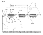
- FIG. 1 shows a device according to the invention for illuminating plants, which are present here in the form of a horizontally extending lawn 3.
- the device 1 has a plurality of light sources 100, each of which has an LED 110 for generating light, and a carrier 10 in the form of a flexible sheet (eg, a fabric), which is designed to carry the light sources 100.
- the carrier 10 is furthermore preferably non-permeable (eg for H 2 O and / or CO 2 ).
- the carrier 10 is adapted to extend flat above the turf surface 3 and in this case has an underside 10a and an upper side 10b facing away from the underside.
- the carrier 10 is preferably arranged in or on a housing 2 set up above the turf surface 3, which in this case has an outer skin 4 with a roof section 4a, the outer skin 4 surrounding a space R of the housing 2 above the turf surface.
- the carrier 10 itself may form a roof section of the housing 2. In this case, the roof portion 4a of the housing 2 shown with the dot-dash line can be omitted.
- the underside 10 a of the carrier faces the turf surface 3, so that the LEDs 110 of the individual light sources 100 fixed on the underside can illuminate the turf surface 3.
- the light sources 100 / LEDs 110 are preferably fixed in equidistant parallel rows on the carrier 10, so that the turf surface 3 can be illuminated as uniformly as possible.
- a plurality of light sources 100 are preferably provided in each row, so that in particular the distance between two adjacent LEDs 110 in a row corresponds to the distance between two adjacent rows.
- the light sources 100 preferably each have two heat sinks 102, 103, each of which is in thermal contact with the associated LED 110, one of the heat sinks 102 being arranged on the lower side 10a of the carrier 10 and the other heat sink 103 being located on the upper side 10b of the Carrier 10, so that the carrier in particular between the heat sinks 102, 103 of the respective light source 100 extends.
- Each light source 100 furthermore has, on the underside 10a of the carrier 10, a light-transmitting cover 101, which is connected to the carrier, for protecting the respective light source 100 or LED 101 from the weathering that covers the respective LED 110.
- one or more preferably flexible lines 20 are integrated into the carrier 10 for growth acceleration and regeneration of the plants / turf surface 3, via which CO 2 reservoir Q CO 2 can be dispensed.
- the at least one line 20 has outlets 21 on the underside 10a of the carrier 10, via which the CO 2 can be expelled.
- the same lines 20 can also for Watering and / or fertilizing the plants or lawn 3 are used.
- the lines 20 are then in connection with a corresponding water source Q '. Water and CO 2 can also be added simultaneously as a mixture via the lines 20 and outlets 21 to the plants / lawn 3.
- separate irrigation lines 22 may be provided for irrigation which have outlets 23 on the underside 10a of the carrier 10 and are then connectable or connected to a separate water source Q '.
Landscapes
- Life Sciences & Earth Sciences (AREA)
- Environmental Sciences (AREA)
- Chemical & Material Sciences (AREA)
- Chemical Kinetics & Catalysis (AREA)
- Biodiversity & Conservation Biology (AREA)
- Botany (AREA)
- Ecology (AREA)
- Forests & Forestry (AREA)
- Cultivation Of Plants (AREA)
Abstract
Description
- Die Erfindung betrifft eine Einrichtung und ein Verfahren zur Beleuchtung von Pflanzen, insbesondere Rasenflächen, insbesondere in Sport- und Fußballstadien.
- Die
EP 2 003 949 B1 beschreibt diesbezüglich ein Verfahren zur Wachstumsbeschleunigung und Regeneration von Rasenflächen, wobei die Rasenfläche zumindest teilbereichsweise oberseitig durch einen nach unten offenen allseitig umschlossenen Raum umschlossen wird und wobei in den Raum CO2 eingeleitet wird und die vom Raum überdeckte Rasenfläche mit einer Beleuchtungseinrichtung mit Licht beaufschlagt wird, wobei das CO2 im Raum durch Konvektion durch die Abwärme der Beleuchtungseinrichtung und/oder einer Rasenheizung verteilt wird. - Weiterhin offenbart die
WO2009124577A1 eine Vorrichtung zur Wachstumsbeschleunigung und Regeneration von Rasenflächen die ein nach unten offenes, auf einer Rasenfläche aufstellbares Gehäuse aufweist, das einen Raum über der Rasenfläche begrenzt, wobei das Gehäuse entweder transparent ausgebildet ist und/oder eine Beleuchtungseinrichtung zum Beleuchten der Rasenfläche aufweist. Das Gehäuse ist mit einer Verfahreinrichtung zum automatischen Bewegen des Gehäuses auf der Rasenfläche ausgebildet ist. - Hiervon ausgehend liegt der vorliegenden Erfindung die Aufgabe zugrunde eine Einrichtung sowie ein Verfahren zum Beleuchten von Pflanzen, insbesondere einer Rasenfläche, weiter zu verbessern.
- Diese Aufgabe wird durch eine Einrichtung mit den Merkmalen des Anspruchs 1 gelöst.
- Gemäß Anspruch 1 ist eine Einrichtung zur Beleuchtung von Pflanzen, insbesondere einer Rasenfläche, vorgesehen, mit:
- einer Mehrzahl an Lichtquellen, und
- einem Träger zum Tragen der Lichtquellen,
- Besonders bevorzugt ist der Träger oder eine Außenhaut der Einrichtung lichtundurchlässig für das mittels der Lichtquellen abgestrahlte (insbesondere sichtbare) Licht oder reduziert zumindest signifikant die Intensität des Lichtes, das durch den Träger bzw. die Außenhaut nach außen dringen kann. Die erfindungsgemäße Einrichtung trägt also besonders bevorzugt wirksam zur Verringerung der sogenannten Lichtverschmutzung ("light pollution") bei, so dass die erfindungsgemäße Einrichtung insbesondere auch in Wohngebieten nachts zum Einsatz kommen kann, ohne die Anwohner erheblich zu stören. Vorzugsweise ist der Träger bzw. die Außenhaut entsprechend schwarz gefärbt bzw. ausgebildet, um insbesondere möglichst viel Licht zu absorbieren.
- Die Lichtquellen (z.B. LEDs) sind vorzugsweise dazu ausgebildet, zumindest im Spektrum von 370nm bis 730nm Licht auszusenden. Bei dem durch die Lichtquellen ausgesendeten Licht handelt es sich bevorzugt um photosynthetisch aktive Strahlung (PAR).
- Hierdurch wird ein höherer Integrationsgrad der erfindungsgemäßen Einrichtung erreicht, mit dem Vorteil, dass der Bauraum eines Gewächshauses zur Wachstumsbeschleunigung und Regeneration der Pflanzen weiter verringerbar sowie leichter aufbaubar ist. Insbesondere besteht die Möglichkeit einen Teil der Außenhaut, insbesondere einen Abschnitt des Daches des Gehäuses bzw. Gewächshauses durch den Träger selbst zu bilden.
- Vorteilhafte Ausgestaltungen der erfindungsgemäßen Einrichtung sind in den entsprechenden Unteransprüchen angegeben und werden nachfolgend beschrieben.
- Der Träger bzw. das Flächengebilde ist erfindungsgemäß flächig, d.h., im Wesentlichen zweidimensional ausgebildet. Das bedeutet, dass der Träger bzw. das Flächengebilde in seiner Erstreckungsebene vorzugsweise wesentlich größere Dimensionen, d.h., Länge und Breite, aufweist, als normal zur Erstreckungsebene (Dicke des Trägers).
- Vorzugweise liegt die Dicke des Trägers senkrecht zu seiner flächenmäßigen Erstreckung im Bereich von 0,5 mm bis 20 mm.
- Der Träger weist weiterhin vorzugsweise eine Unterseite sowie eine der Unterseite abgewandte Oberseite auf, die sich jeweils entlang der Erstreckungsebene des Trägers erstrecken, d.h. quer zur Dicke des Trägers, wobei diese beiden Seiten jeweils vorzugsweise eine Fläche im Bereich von 5 m x 6 m bis 20 m x 40 m (z.B. 5 m x 12 m) aufweisen, und/oder eine Fläche im Bereich von 30 m2 bis 400 m2.
- An der Unterseite des Trägers, die bei einer bestimmungsgemäß angeordneten Einrichtung den Pflanzen bzw. der Rasenfläche zugewandt ist, sind vorzugsweise die Lichtquellen bzw. LEDs angeordnet.
- Die Lichtquellen weisen zur Erzeugung des zur Beleuchtung der Pflanzen verwendeten Lichtes jeweils eine LED (oder einen anderen geeigneten Lichtemitter) auf. LED steht hierbei für Light Emitting Diode oder Lichtdiode, d.h., für ein lichtemittierendes Halbleiter-Bauelement, dessen elektrische Eigenschaften insbesondere einer Diode entsprechen.
- Weiterhin kann jede Lichtquelle jeweils einen Kühlkörper aufweisen, der in thermischen Kontakt mit der zugeordneten LED steht und der jeweils an der Unterseite des Trägers angeordnet ist, sowie vorzugsweise jeweils einen weiteren Kühlkörper, der ebenfalls mit der zugeordneten LED in thermischen Kontakt und der jeweils an der Oberseite des Trägers angeordnet ist, so dass der Träger insbesondere zwischen den Kühlkörpern der jeweiligen Lichtquelle verläuft.
- Jede Lichtquelle weist weiterhin an der Unterseite des Trägers eine lichtdurchlässige Abdeckung zum Schutz der jeweiligen Lichtquelle bzw. LED auf, die, insbesondere zusammen mit dem Träger, die jeweilige LED umgibt und gegen Feuchtigkeit abschirmt.
- Gemäß einer bevorzugten Ausführungsform der Erfindung ist vorgesehen, dass das Flächengebilde eines der folgenden Flächengebilde ist:
- ein textiles Flächengebilde, vorzugsweise ein Gewebe, vorzugsweise aufweisend Polyethylen (aber auch PU, PTFE, PVC, wie unten genannt, sind möglich)
- ein Gewebe,
- ein Gewirk,
- ein Gestrick,
- ein Geflecht,
- ein Nähgewirk,
- ein Vliesstoff,
- ein Filz,
- eine Folie, vorzugsweise aus einem Kunststoff.
- Eine erfindungsgemäße Kunststofffolie kann aus Polyolefinen wie z.B. Polyethylen (PE) oder Polypropylen (PP) hergestellt sein bzw. aus diesen Stoffen bestehen bzw. diese Stoffe aufweisen. Weiterhin kann eine bei der Erfindung verwendete Folie Polyvinylchlorid (PVC), Polystyrol (PS), Polyester, Polycarbonat (PC) oder Polyethylenterephthalat (PET) aufweisen bzw. aus einem dieser Stoffe bestehen.
- Weiterhin kann die Folie aus einer Kombination dieser Stoffe bestehen, z.B. in Form eines Mehrschicht-Verbundes aus einer Kombination unterschiedlicher Kunststoffe. Hierdurch kann z.B. das Permeationsverhalten der Folie eingestellt werden.
- Gemäß einer bevorzugten Ausführungsform der Erfindung ist der Träger bzw. das Flächengebilde vorzugsweise nicht-permeabel für Flüssigkeiten und/oder Gase (wie z.B. CO2).
- Gemäß einer weiteren Ausführungsform der Erfindung ist vorgesehen, dass die Einrichtung ein Mittel zum Führen und Abgeben von CO2 aufweist, vorzugsweise in Form einer flexiblen Leitung (z.B. vorzugsweise in Form eines flexiblen Schlauchs), das an dem Träger festgelegt ist und einen oder mehrere Auslässe zum Auslassen von CO2 aufweist.
- Gemäß einer weiteren Ausführungsform der Erfindung ist vorgesehen, dass das Mittel bzw. die flexible Leitung vom Träger zumindest abschnittsweise umgeben ist, d.h., im Querschnitt vom Träger umschlossen wird. Hierbei können die Auslässe des Mittels bzw. der Leitung in Form von Düsen aus dem Träger herausragen, und zwar bevorzugt an einer Unterseite des Trägers, an der auch die LEDs vorzugsweise festgelegt sind. Diese Unterseite ist bei einer bestimmungsgemäß angeordneten Einrichtung den zu beleuchtenden Pflanzen bzw. der Rasenfläche zugewandt.
- Weiterhin ist gemäß einer Ausführungsform der Erfindung vorgesehen, dass das Mittel bzw. die Leitung mit einem CO2-Speicher verbunden oder verbindbar ist, so dass CO2 über das Mittel bzw. die Leitung abgebbar ist und die Pflanzen kontaktieren kann.
- Dieses Mittel bzw. diese Leitung kann weiterhin dazu ausgebildet sein, Wasser zum Bewässern der Pflanzen zu führen und über die Auslässe abzugeben, wobei insbesondere das Mittel mit einer Wasserquelle verbunden ist oder verbindbar ist. Ggf. können Wasser und CO2 gemischt werden und gemeinsam über das Mittel bzw. die Leitung sowie deren Auslässe abgegeben werden. Vorzugsweise werden Wasser und CO2 getrennt zugeführt. Des Weiteren können auch andere Nährstoffe (z.B. Dünger) über das Mittel bzw. die Leitung sowie deren Auslässe abgegeben werden (z.B. durch Vermischen mit dem Wasser etc.).
- Alternativ hierzu kann gemäß einer Ausführungsform vorgesehen sein, dass die Einrichtung eine separate, vorzugsweise flexible, Bewässerungsleitung zum Führen und Abgeben von Wasser aufweist (z.B. in Form eines flexiblen Schlauchs), die an dem Träger festgelegt ist und einen oder mehrere Auslässe zum Auslassen von Wasser aufweist.
- Auch die Bewässerungsleitung ist bevorzugt vom Träger zumindest abschnittsweise umgeben, d.h. wird im Querschnitt vom Träger umschlossen. Mit anderen Worten sind also vorzugsweise die oben dargelegte Leitung bzw. Mittel zum Abgeben von CO2 sowie ggf. die Bewässerungsleitung in den Träger integriert.
- Ebenfalls können die Auslässe der Bewässerungsleitung in Form von Düsen aus dem Träger, und zwar insbesondere an dessen Unterseite, herausragen.
- Gemäß einer bevorzugten Ausführungsform der Erfindung sind die Lichtquellen bzw. LEDs in vorzugsweise parallelen Reihen am Träger angeordnet, so dass sie bevorzugt gleichmäßig über den Träger verteilt sind.
- Weiterhin ist gemäß einer bevorzugten Ausführungsform der Erfindung vorgesehen, dass sich das Mittel zum Abgeben von CO2 zumindest abschnittsweise zwischen benachbarten Lichtquellen bzw. LEDs entlang des Trägers erstreckt.
- Gleiches gilt vorzugsweise auch für die besagte Bewässerungsleitung.
- Auf diese Weise können, vorzugsweise ebenfalls gleichmäßig über den Träger verteilt, CO2 und/oder Wasser auf die Pflanzen nach unten hin abgegeben werden.
- Besonders bevorzugt weist die Einrichtung gemäß einer Ausführungsform der Erfindung ein nach unten hin offenes Gehäuse auf, das eine Außenhaut aufweist, die dazu eingerichtet und vorgesehen ist, einen Raum oberhalb der Pflanzen, insbesondere der Rasenfläche, zu begrenzen, wobei der Träger in jenem Raum angeordnet ist oder zumindest einen Teil der Außenhaut, vorzugsweise einen Dachabschnitt der Außenhaut, bildet.
- Ein derartiges Gehäuse bzw. Gewächshaus kann weiterhin verfahrbar ausgebildet sein, so dass es entlang der Rasenfläche bzw. entlang der Pflanzen, insbesondere in der Horizontalen, verfahren werden kann, um insbesondere großflächige Rasenflächen zu behandeln.
- Weiterhin kann die Einrichtung ein separates Heiz- oder Kühlmittel aufweisen, das dazu ausgebildet ist, den Raum des Gehäuses auf eine vordefinierte Temperatur, die insbesondere dem Pflanzenwachstum förderlich ist, zu heizen oder zu kühlen.
- Gemäß einem weiteren Aspekt der Erfindung ist ein Verfahren zum Beleuchten von Pflanzen, insbesondere einer Rasenfläche, gemäß Anspruch 15 vorgesehen, wobei eine erfindungsgemäße Einrichtung verwendet wird, und die Pflanzen mittels der Lichtquellen dieser Einrichtung beleuchtet werden.
- Hierbei werden gemäß einem Ausführungsbeispiel des Verfahrens weiterhin die Pflanzen, insbesondere die Rasenfläche, mittels der Einrichtung mit CO2 und/oder Wasser beaufschlagt sowie vorzugsweise auch mit einem Dünger.
- Das CO2 kann in dem Gehäuse z.B. durch Konvektion sowie durch die Abwärme der Lichtquellen/LEDs oder einer etwaigen Rasenheizung verteilt werden.
- Weiterhin wird bevorzugt bei dem erfindungsgemäßen Verfahren der Gasgehalt im Gehäuse bzw. in dem Raum des Gehäuses auf 500 bis 2.500 ppm CO2 eingestellt.
- Weiterhin wird vorzugsweise bei dem erfindungsgemäßen Verfahren bzw. bei der erfindungsgemäßen Einrichtung die Größe des Raumes bzw. des Gehäuses so gewählt, dass sich bei einer vordefinierten Standzeit von vorzugsweise vier bis zwölf Stunden innerhalb des Gehäuses bzw. in dem Raum eine Temperatur von zumindest 6° C einstellt. Die Temperatur innerhalb des Raumes kann zusätzlich bzw. alternativ mit dem separaten Heizmittel auf eine vordefinierte Temperatur eingestellt werden.
- Gemäß einem Ausführungsbeispiel der erfindungsgemäßen Einrichtung bzw. des erfindungsgemäßen Verfahrens ist insbesondere vorgesehen, dass der Raum des Gehäuses eine horizontale Grundfläche im Bereich 5 m x 6 m bis 20 m x 40 m aufweist, und/oder dass der umbaute bzw. geschlossene Raum eine Grundfläche von 30 m2 bis 400 m2 umfasst.
- Weitere Merkmale und Vorteile der Erfindung sollen bei den nachfolgenden Figurenbeschreibungen von Ausführungsbeispielen der Erfindung anhand der Figuren erläutert werden. Es zeigen:
- Fig. 1
- eine schematische Schnittansicht einer erfindungsgemäßen Einrichtung.
- Die
Figur 1 zeigt eine erfindungsgemäße Einrichtung zur Beleuchtung von Pflanzen, die hier in Form einer horizontal erstreckten Rasenfläche 3 vorliegen. - Die Einrichtung 1 weist eine Mehrzahl an Lichtquellen 100 auf, die zur Lichterzeugung jeweils über eine LED 110 verfügen, sowie einem Träger 10 in Form eines flexiblen Flächengebildes (z.B. ein Gewebe), der zum Tragen der Lichtquellen 100 ausgebildet ist. Der Träger 10 ist weiterhin vorzugsweise nicht-permeabel ausgebildet (z.B. für H2O und/oder CO2).
- Der Träger 10 ist dazu eingerichtet, sich flächig oberhalb der Rasenfläche 3 zu erstrecken und weist dabei eine Unterseite 10a auf sowie eine der Unterseite abgewandte Oberseite 10b.
- Der Träger 10 wird vorzugsweise in oder an einem oberhalb der Rasenfläche 3 aufgestellten Gehäuse 2 angeordnet, das in diesem Fall eine Außenhaut 4 mit einem Dachabschnitt 4a aufweist, wobei die Außenhaut 4 einen Raum R des Gehäuses 2 oberhalb der Rasenfläche umgibt. Alternativ kann der Träger 10 selbst einen Dachabschnitt des Gehäuses 2 bilden. In diesem Fall kann der mit der strichpunktierten Linie dargestellte Dachabschnitt 4a des Gehäuses 2 entfallen.
- Die Unterseite 10a des Trägers ist der Rasenfläche 3 zugewandt, so dass die an der Unterseite festgelegten LEDs 110 der einzelnen Lichtquellen 100 die Rasenfläche 3 beleuchten können. Hierbei sind die Lichtquellen 100 /LEDs 110 vorzugsweise in äquidistanten parallelen Reihen am Träger 10 festgelegt, so dass die Rasenfläche 3 möglichst gleichmäßig beleuchtbar ist. Hierbei sind vorzugsweise in jeder Reihe eine Mehrzahl an Lichtquellen 100 vorgesehen, so dass insbesondere der Abstand zweier benachbarter LEDs 110 in einer Reihe dem Abstand zweier benachbarter Reihen entspricht.
- Weiterhin weisen die Lichtquellen 100 vorzugsweise jeweils zwei Kühlkörper 102, 103 auf, die jeweils in thermischen Kontakt mit der zugeordneten LED 110 stehen, wobei einer der Kühlkörper 102 an der Unterseite 10a des Trägers 10 angeordnet ist und der andere Kühlkörper 103 an der Oberseite 10b des Trägers 10, so dass der Träger insbesondere zwischen den Kühlkörpern 102, 103 der jeweiligen Lichtquelle 100 verläuft.
- Jede Lichtquelle 100 weist weiterhin an der Unterseite 10a des Trägers 10 eine lichtdurchlässige, mit dem Träger verbundene Abdeckung 101 zum Schutz der jeweiligen Lichtquelle 100 bzw. LED 101 vor Witterungseinflüssen auf, die die jeweilige LED 110 überdeckt.
- Abgesehen von der Beleuchtung der Pflanzen/Rasenfläche 3 sind zur Wachstumsbeschleunigung und Regeneration der Pflanzen/Rasenfläche 3 eine oder mehrere vorzugsweise flexible Leitungen 20 in den Träger 10 integriert, über die aus einem CO2-Speicher Q CO2 ausgegeben werden kann. Hierzu weist die mindestens eine Leitung 20 Auslässe 21 an der Unterseite 10a des Trägers 10 auf, über die das CO2 ausgestoßen werden kann. Die gleichen Leitungen 20 können auch zum Bewässern und/oder Düngen der Pflanzen bzw. Rasenfläche 3 verwendet werden. Hierzu stehen die Leitungen 20 dann in Verbindung mit einer entsprechenden Wasserquelle Q'. Wasser und CO2 können auch gleichzeitig als Gemisch über die Leitungen 20 und Auslässe 21 auf die Pflanzen/Rasenfläche 3 gegeben werden. Alternativ hierzu können für die Bewässerung separate Bewässerungsleitungen 22 vorhanden sein, die über Auslässe 23 an der Unterseite 10a des Trägers 10 verfügen und dann mit einer separaten Wasserquelle Q' verbindbar bzw. verbunden sind.
Bezugszeichen 1 Einrichtung 2 Gehäuse 3 Pflanzen/Rasenfläche 4 Außenhaut 4a Dachabschnitt 10 Träger 10a Unterseite 10b Oberseite 20 Leitung 21 Auslass 22 Bewässerungsleitung 23 Auslass 100 Lichtquelle 101 Abdeckung 102, 103 Kühlkörper
Claims (15)
- Einrichtung (1) zur Beleuchtung von Pflanzen (3), insbesondere einer Rasenfläche (3), mit:- einer Mehrzahl an Lichtquellen (100), und- einem Träger (10) zum Tragen der Lichtquellen (100),dadurch gekennzeichnet,
dass der Träger (10) als flexibles Flächengebilde ausgebildet ist, wobei die Lichtquellen (100) an dem Träger (10) festgelegt sind. - Einrichtung nach Anspruch 1, dadurch gekennzeichnet, dass das Flächengebilde eines der folgenden Flächengebildet ist:- ein textiles Flächengebilde, vorzugsweise ein Gewebe, oder- eine Folie, vorzugsweise aus einem Kunststoff.
- Einrichtung nach Anspruch 1 oder 2, dadurch gekennzeichnet, dass der Träger nicht-permeabel für Flüssigkeiten, insbesondere für Wasser, und/oder nicht-permeabel für Gase, insbesondere für CO2, ausgebildet ist.
- Einrichtung nach einem der vorhergehenden Ansprüche, dadurch gekennzeichnet, dass die Einrichtung (1) ein Mittel (20) zum Führen und Abgeben von CO2 aufweist, vorzugsweise in Form einer flexiblen Leitung, das an dem Träger (10) festgelegt ist und einen oder mehrere Auslässe (21) zum Auslassen von CO2 aufweist.
- Einrichtung nach Anspruch 4, dadurch gekennzeichnet, dass das Mittel (20) vom Träger (10) zumindest abschnittsweise umgeben ist.
- Einrichtung nach Anspruch 4 oder 5, dadurch gekennzeichnet, dass das Mittel (20) mit einem CO2-Speicher (Q) verbunden oder verbindbar ist.
- Einrichtung nach einem der Ansprüche 4 bis 6, dadurch gekennzeichnet, dass das Mittel (20) weiterhin dazu ausgebildet ist, Wasser zum Bewässern der Pflanzen (3), insbesondere der Rasenfläche (3), zu führen und abzugeben, wobei insbesondere das Mittel (20) mit einer Wasserquelle (Q') verbunden ist oder verbindbar ist.
- Einrichtung nach einem der vorhergehenden Ansprüche, dadurch gekennzeichnet, dass die Einrichtung (1) eine vorzugsweise flexible Bewässerungsleitung (22) zum Führen und Abgeben von Wasser aufweist, die an dem Träger (10) festgelegt ist und einen oder mehrere Auslässe (23) zum Auslassen von Wasser aufweist.
- Einrichtung nach Anspruch 8, dadurch gekennzeichnet, dass die Bewässerungsleitung (22) vom Träger (10) zumindest abschnittsweise umgeben ist.
- Einrichtung nach einem der vorhergehenden Ansprüche, dadurch gekennzeichnet, dass jede der Lichtquellen (100) eine LED (110) aufweist.
- Einrichtung nach einem der vorhergehenden Ansprüche, dadurch gekennzeichnet, dass die Lichtquellen (100) in Reihen am Träger (10) angeordnet sind.
- Einrichtung nach Anspruch 4 oder einem der Ansprüche 5 bis 11 soweit rückbezogen auf Anspruch 4, dadurch gekennzeichnet, dass sich das Mittel (20) zum Abgeben von CO2 zumindest abschnittsweise zwischen benachbarten Lichtquellen (100) entlang des Trägers (10) erstreckt.
- Einrichtung nach Anspruch 8 oder einem der Ansprüche 9 bis 12 soweit rückbezogen auf Anspruch 8, dadurch gekennzeichnet, dass sich die Bewässerungsleitung (22) zumindest abschnittsweise zwischen benachbarten Lichtquellen (100) entlang des Trägers (10) erstreckt.
- Einrichtung nach einem der vorhergehenden Ansprüche, dadurch gekennzeichnet, dass die Einrichtung (1) ein nach unten hin offenes Gehäuse (2) aufweist, das eine Außenhaut (4) aufweist, die dazu eingerichtet und vorgesehen ist, einen Raum (R) oberhalb der Pflanzen (3), insbesondere der Rasenfläche (3), zu begrenzen, wobei der Träger (10) in jenem Raum (R) angeordnet ist oder zumindest einen Teil der Außenhaut (4), vorzugsweise einen Dachabschnitt (4a) der Außenhaut (4), bildet.
- Verfahren zum Beleuchten von Pflanzen (3), insbesondere einer Rasenfläche (3), wobei eine Einrichtung (1) gemäß einem der Ansprüche 1 bis 14 bereitgestellt wird, und die Pflanzen (3) mittels der Lichtquellen (100) beleuchtet werden, und wobei vorzugsweise die Pflanzen (3), insbesondere die Rasenfläche (3), mittels der Einrichtung (1) mit CO2 und/oder Wasser beaufschlagt werden.
Priority Applications (1)
| Application Number | Priority Date | Filing Date | Title |
|---|---|---|---|
| EP15002746.4A EP3146834B1 (de) | 2015-09-23 | 2015-09-23 | Einrichtung und verfahren zur beleuchtung von pflanzen, insbesondere rasenflächen |
Applications Claiming Priority (1)
| Application Number | Priority Date | Filing Date | Title |
|---|---|---|---|
| EP15002746.4A EP3146834B1 (de) | 2015-09-23 | 2015-09-23 | Einrichtung und verfahren zur beleuchtung von pflanzen, insbesondere rasenflächen |
Publications (2)
| Publication Number | Publication Date |
|---|---|
| EP3146834A1 true EP3146834A1 (de) | 2017-03-29 |
| EP3146834B1 EP3146834B1 (de) | 2020-05-13 |
Family
ID=54198917
Family Applications (1)
| Application Number | Title | Priority Date | Filing Date |
|---|---|---|---|
| EP15002746.4A Active EP3146834B1 (de) | 2015-09-23 | 2015-09-23 | Einrichtung und verfahren zur beleuchtung von pflanzen, insbesondere rasenflächen |
Country Status (1)
| Country | Link |
|---|---|
| EP (1) | EP3146834B1 (de) |
Cited By (2)
| Publication number | Priority date | Publication date | Assignee | Title |
|---|---|---|---|---|
| WO2025147191A1 (en) * | 2024-01-03 | 2025-07-10 | Alva Technology | Grow lighting system |
| US12478004B2 (en) | 2021-12-08 | 2025-11-25 | Musco Corporation | Apparatus, method, and system for improved turf or grass growth |
Citations (6)
| Publication number | Priority date | Publication date | Assignee | Title |
|---|---|---|---|---|
| DE202006002460U1 (de) * | 2006-02-09 | 2006-07-06 | Drabner, Ulrike | Abdeckeinrichtung für Spielfelder |
| DE202006004651U1 (de) * | 2006-03-15 | 2006-07-06 | Drabner, Ulrike | Mobile Abdeckungseinrichtung für Spielfelder |
| EP1802379A1 (de) * | 2004-09-17 | 2007-07-04 | Intravision AS | Hängende abdeckung |
| WO2009124577A1 (de) | 2008-04-11 | 2009-10-15 | Linde Ag | Vorrichtung und verfahren zur wachstumsbeschleunigung und regeneration von rasenflächen |
| US20130000185A1 (en) * | 2010-03-22 | 2013-01-03 | Koninklijke Philips Electronics, N.V. | Lighting system with cooling arrangement |
| EP2003949B1 (de) | 2006-04-13 | 2015-03-04 | Linde AG | Verfahren zur Wachstumsbeschleunigung |
-
2015
- 2015-09-23 EP EP15002746.4A patent/EP3146834B1/de active Active
Patent Citations (6)
| Publication number | Priority date | Publication date | Assignee | Title |
|---|---|---|---|---|
| EP1802379A1 (de) * | 2004-09-17 | 2007-07-04 | Intravision AS | Hängende abdeckung |
| DE202006002460U1 (de) * | 2006-02-09 | 2006-07-06 | Drabner, Ulrike | Abdeckeinrichtung für Spielfelder |
| DE202006004651U1 (de) * | 2006-03-15 | 2006-07-06 | Drabner, Ulrike | Mobile Abdeckungseinrichtung für Spielfelder |
| EP2003949B1 (de) | 2006-04-13 | 2015-03-04 | Linde AG | Verfahren zur Wachstumsbeschleunigung |
| WO2009124577A1 (de) | 2008-04-11 | 2009-10-15 | Linde Ag | Vorrichtung und verfahren zur wachstumsbeschleunigung und regeneration von rasenflächen |
| US20130000185A1 (en) * | 2010-03-22 | 2013-01-03 | Koninklijke Philips Electronics, N.V. | Lighting system with cooling arrangement |
Cited By (3)
| Publication number | Priority date | Publication date | Assignee | Title |
|---|---|---|---|---|
| US12478004B2 (en) | 2021-12-08 | 2025-11-25 | Musco Corporation | Apparatus, method, and system for improved turf or grass growth |
| WO2025147191A1 (en) * | 2024-01-03 | 2025-07-10 | Alva Technology | Grow lighting system |
| NL2036733B1 (en) * | 2024-01-03 | 2025-07-18 | Alva Tech | Grow lighting system |
Also Published As
| Publication number | Publication date |
|---|---|
| EP3146834B1 (de) | 2020-05-13 |
Similar Documents
| Publication | Publication Date | Title |
|---|---|---|
| DE102018126555A1 (de) | Abgeschlossene Klimazelle mit beweglich angeordneten Beleuchtungsplattformen | |
| DE102017117373A1 (de) | Schädlingsbekämpfungsvorrichtung | |
| DE102018123378A1 (de) | Torfmooswand | |
| EP3146834B1 (de) | Einrichtung und verfahren zur beleuchtung von pflanzen, insbesondere rasenflächen | |
| DE102011113711B4 (de) | Vorrichtung zur Beleuchtung eines Kraftfahrzeuginnenraums | |
| DE102016206174B4 (de) | Anzeigeelement, Anzeigevorrichtung mit einem solchen Anzeigeelement und Elektrogerät mit einer solchen Anzeigevorrichtung | |
| DE102015117902B3 (de) | Beleuchtbarer Pflanzenbehälter | |
| CH715534A1 (de) | Optik und Tischleuchte. | |
| DE102012214478A1 (de) | Längliches Leuchtmodul mit vergossenem Leuchtband | |
| DE202009006868U1 (de) | Rundumleuchte, vorzugsweise Rundumkennleuchte | |
| DE102011114993A1 (de) | Laborabzug und insbesondere Sicherheitswerkbank mit LED-Beleuchtung | |
| DE202017101739U1 (de) | Zuchtvorrichtung zum Züchten von Organismen, insbesondere Pflanzenzuchtvorrichtung zum Züchten von Pflanzen | |
| EP2927890B1 (de) | Signalgeber zur abgabe eines lichtsignals | |
| DE202016102798U1 (de) | Flächenleuchtelement für den Innenraum von Fahrzeugen | |
| DE202009015826U1 (de) | Leuchtkörper | |
| EP2567614B1 (de) | Inkubator | |
| DE102014011642B3 (de) | Anlagen zum Kultivieren von Pflanzen | |
| DE102010063869A1 (de) | Dunstabzugshaube mit Beleuchtungsvorrichtung | |
| DE102018201043A1 (de) | Optoelektronisches bauelement sowie bauelementverbund daraus | |
| DE102018101088B4 (de) | Fluidkühlbare LED-Leuchte sowie deren Verwendung in einem Verfahren zur Belichtung mit photosynthetisch aktiver Strahlung | |
| DE102011101610B3 (de) | Leuchte | |
| EP3467387B1 (de) | Dunstabzugshaube mit hinterleuchtetem fettfilter | |
| DE102021126012A1 (de) | Bioreaktor | |
| DE102021209086A1 (de) | Konsole für einen Fahrzeuginnenraum | |
| DE202010001366U1 (de) | Beleuchtungseinrichtung |
Legal Events
| Date | Code | Title | Description |
|---|---|---|---|
| PUAI | Public reference made under article 153(3) epc to a published international application that has entered the european phase |
Free format text: ORIGINAL CODE: 0009012 |
|
| STAA | Information on the status of an ep patent application or granted ep patent |
Free format text: STATUS: THE APPLICATION HAS BEEN PUBLISHED |
|
| AK | Designated contracting states |
Kind code of ref document: A1 Designated state(s): AL AT BE BG CH CY CZ DE DK EE ES FI FR GB GR HR HU IE IS IT LI LT LU LV MC MK MT NL NO PL PT RO RS SE SI SK SM TR |
|
| AX | Request for extension of the european patent |
Extension state: BA ME |
|
| STAA | Information on the status of an ep patent application or granted ep patent |
Free format text: STATUS: REQUEST FOR EXAMINATION WAS MADE |
|
| 17P | Request for examination filed |
Effective date: 20180119 |
|
| RBV | Designated contracting states (corrected) |
Designated state(s): AL AT BE BG CH CY CZ DE DK EE ES FI FR GB GR HR HU IE IS IT LI LT LU LV MC MK MT NL NO PL PT RO RS SE SI SK SM TR |
|
| RAP1 | Party data changed (applicant data changed or rights of an application transferred) |
Owner name: SEEGROW (DEVELOPMENTS) LIMITED |
|
| RAP1 | Party data changed (applicant data changed or rights of an application transferred) |
Owner name: SEEGROW (DEVELOPMENTS) LIMITED |
|
| GRAP | Despatch of communication of intention to grant a patent |
Free format text: ORIGINAL CODE: EPIDOSNIGR1 |
|
| STAA | Information on the status of an ep patent application or granted ep patent |
Free format text: STATUS: GRANT OF PATENT IS INTENDED |
|
| RIC1 | Information provided on ipc code assigned before grant |
Ipc: A01G 20/00 20180101ALN20190912BHEP Ipc: A01G 7/04 20060101AFI20190912BHEP Ipc: A01G 7/02 20060101ALI20190912BHEP |
|
| RIC1 | Information provided on ipc code assigned before grant |
Ipc: A01G 7/04 20060101AFI20190918BHEP Ipc: A01G 7/02 20060101ALI20190918BHEP Ipc: A01G 20/00 20180101ALN20190918BHEP |
|
| INTG | Intention to grant announced |
Effective date: 20191009 |
|
| GRAS | Grant fee paid |
Free format text: ORIGINAL CODE: EPIDOSNIGR3 |
|
| GRAA | (expected) grant |
Free format text: ORIGINAL CODE: 0009210 |
|
| STAA | Information on the status of an ep patent application or granted ep patent |
Free format text: STATUS: THE PATENT HAS BEEN GRANTED |
|
| AK | Designated contracting states |
Kind code of ref document: B1 Designated state(s): AL AT BE BG CH CY CZ DE DK EE ES FI FR GB GR HR HU IE IS IT LI LT LU LV MC MK MT NL NO PL PT RO RS SE SI SK SM TR |
|
| REG | Reference to a national code |
Ref country code: GB Ref legal event code: FG4D Free format text: NOT ENGLISH |
|
| REG | Reference to a national code |
Ref country code: CH Ref legal event code: EP |
|
| REG | Reference to a national code |
Ref country code: DE Ref legal event code: R096 Ref document number: 502015012555 Country of ref document: DE |
|
| REG | Reference to a national code |
Ref country code: AT Ref legal event code: REF Ref document number: 1268989 Country of ref document: AT Kind code of ref document: T Effective date: 20200615 |
|
| REG | Reference to a national code |
Ref country code: LT Ref legal event code: MG4D |
|
| REG | Reference to a national code |
Ref country code: NL Ref legal event code: MP Effective date: 20200513 |
|
| PG25 | Lapsed in a contracting state [announced via postgrant information from national office to epo] |
Ref country code: FI Free format text: LAPSE BECAUSE OF FAILURE TO SUBMIT A TRANSLATION OF THE DESCRIPTION OR TO PAY THE FEE WITHIN THE PRESCRIBED TIME-LIMIT Effective date: 20200513 Ref country code: PT Free format text: LAPSE BECAUSE OF FAILURE TO SUBMIT A TRANSLATION OF THE DESCRIPTION OR TO PAY THE FEE WITHIN THE PRESCRIBED TIME-LIMIT Effective date: 20200914 Ref country code: NO Free format text: LAPSE BECAUSE OF FAILURE TO SUBMIT A TRANSLATION OF THE DESCRIPTION OR TO PAY THE FEE WITHIN THE PRESCRIBED TIME-LIMIT Effective date: 20200813 Ref country code: GR Free format text: LAPSE BECAUSE OF FAILURE TO SUBMIT A TRANSLATION OF THE DESCRIPTION OR TO PAY THE FEE WITHIN THE PRESCRIBED TIME-LIMIT Effective date: 20200814 Ref country code: IS Free format text: LAPSE BECAUSE OF FAILURE TO SUBMIT A TRANSLATION OF THE DESCRIPTION OR TO PAY THE FEE WITHIN THE PRESCRIBED TIME-LIMIT Effective date: 20200913 Ref country code: SE Free format text: LAPSE BECAUSE OF FAILURE TO SUBMIT A TRANSLATION OF THE DESCRIPTION OR TO PAY THE FEE WITHIN THE PRESCRIBED TIME-LIMIT Effective date: 20200513 Ref country code: LT Free format text: LAPSE BECAUSE OF FAILURE TO SUBMIT A TRANSLATION OF THE DESCRIPTION OR TO PAY THE FEE WITHIN THE PRESCRIBED TIME-LIMIT Effective date: 20200513 |
|
| PG25 | Lapsed in a contracting state [announced via postgrant information from national office to epo] |
Ref country code: BG Free format text: LAPSE BECAUSE OF FAILURE TO SUBMIT A TRANSLATION OF THE DESCRIPTION OR TO PAY THE FEE WITHIN THE PRESCRIBED TIME-LIMIT Effective date: 20200813 Ref country code: RS Free format text: LAPSE BECAUSE OF FAILURE TO SUBMIT A TRANSLATION OF THE DESCRIPTION OR TO PAY THE FEE WITHIN THE PRESCRIBED TIME-LIMIT Effective date: 20200513 Ref country code: HR Free format text: LAPSE BECAUSE OF FAILURE TO SUBMIT A TRANSLATION OF THE DESCRIPTION OR TO PAY THE FEE WITHIN THE PRESCRIBED TIME-LIMIT Effective date: 20200513 Ref country code: LV Free format text: LAPSE BECAUSE OF FAILURE TO SUBMIT A TRANSLATION OF THE DESCRIPTION OR TO PAY THE FEE WITHIN THE PRESCRIBED TIME-LIMIT Effective date: 20200513 |
|
| PG25 | Lapsed in a contracting state [announced via postgrant information from national office to epo] |
Ref country code: NL Free format text: LAPSE BECAUSE OF FAILURE TO SUBMIT A TRANSLATION OF THE DESCRIPTION OR TO PAY THE FEE WITHIN THE PRESCRIBED TIME-LIMIT Effective date: 20200513 Ref country code: AL Free format text: LAPSE BECAUSE OF FAILURE TO SUBMIT A TRANSLATION OF THE DESCRIPTION OR TO PAY THE FEE WITHIN THE PRESCRIBED TIME-LIMIT Effective date: 20200513 |
|
| PG25 | Lapsed in a contracting state [announced via postgrant information from national office to epo] |
Ref country code: ES Free format text: LAPSE BECAUSE OF FAILURE TO SUBMIT A TRANSLATION OF THE DESCRIPTION OR TO PAY THE FEE WITHIN THE PRESCRIBED TIME-LIMIT Effective date: 20200513 Ref country code: DK Free format text: LAPSE BECAUSE OF FAILURE TO SUBMIT A TRANSLATION OF THE DESCRIPTION OR TO PAY THE FEE WITHIN THE PRESCRIBED TIME-LIMIT Effective date: 20200513 Ref country code: SM Free format text: LAPSE BECAUSE OF FAILURE TO SUBMIT A TRANSLATION OF THE DESCRIPTION OR TO PAY THE FEE WITHIN THE PRESCRIBED TIME-LIMIT Effective date: 20200513 Ref country code: IT Free format text: LAPSE BECAUSE OF FAILURE TO SUBMIT A TRANSLATION OF THE DESCRIPTION OR TO PAY THE FEE WITHIN THE PRESCRIBED TIME-LIMIT Effective date: 20200513 Ref country code: EE Free format text: LAPSE BECAUSE OF FAILURE TO SUBMIT A TRANSLATION OF THE DESCRIPTION OR TO PAY THE FEE WITHIN THE PRESCRIBED TIME-LIMIT Effective date: 20200513 Ref country code: CZ Free format text: LAPSE BECAUSE OF FAILURE TO SUBMIT A TRANSLATION OF THE DESCRIPTION OR TO PAY THE FEE WITHIN THE PRESCRIBED TIME-LIMIT Effective date: 20200513 Ref country code: RO Free format text: LAPSE BECAUSE OF FAILURE TO SUBMIT A TRANSLATION OF THE DESCRIPTION OR TO PAY THE FEE WITHIN THE PRESCRIBED TIME-LIMIT Effective date: 20200513 |
|
| PGFP | Annual fee paid to national office [announced via postgrant information from national office to epo] |
Ref country code: GB Payment date: 20201016 Year of fee payment: 6 |
|
| REG | Reference to a national code |
Ref country code: DE Ref legal event code: R097 Ref document number: 502015012555 Country of ref document: DE |
|
| PG25 | Lapsed in a contracting state [announced via postgrant information from national office to epo] |
Ref country code: PL Free format text: LAPSE BECAUSE OF FAILURE TO SUBMIT A TRANSLATION OF THE DESCRIPTION OR TO PAY THE FEE WITHIN THE PRESCRIBED TIME-LIMIT Effective date: 20200513 Ref country code: SK Free format text: LAPSE BECAUSE OF FAILURE TO SUBMIT A TRANSLATION OF THE DESCRIPTION OR TO PAY THE FEE WITHIN THE PRESCRIBED TIME-LIMIT Effective date: 20200513 |
|
| PLBE | No opposition filed within time limit |
Free format text: ORIGINAL CODE: 0009261 |
|
| STAA | Information on the status of an ep patent application or granted ep patent |
Free format text: STATUS: NO OPPOSITION FILED WITHIN TIME LIMIT |
|
| REG | Reference to a national code |
Ref country code: DE Ref legal event code: R119 Ref document number: 502015012555 Country of ref document: DE |
|
| 26N | No opposition filed |
Effective date: 20210216 |
|
| PG25 | Lapsed in a contracting state [announced via postgrant information from national office to epo] |
Ref country code: MC Free format text: LAPSE BECAUSE OF FAILURE TO SUBMIT A TRANSLATION OF THE DESCRIPTION OR TO PAY THE FEE WITHIN THE PRESCRIBED TIME-LIMIT Effective date: 20200513 |
|
| REG | Reference to a national code |
Ref country code: CH Ref legal event code: PL |
|
| PG25 | Lapsed in a contracting state [announced via postgrant information from national office to epo] |
Ref country code: SI Free format text: LAPSE BECAUSE OF FAILURE TO SUBMIT A TRANSLATION OF THE DESCRIPTION OR TO PAY THE FEE WITHIN THE PRESCRIBED TIME-LIMIT Effective date: 20200513 |
|
| REG | Reference to a national code |
Ref country code: BE Ref legal event code: MM Effective date: 20200930 |
|
| PG25 | Lapsed in a contracting state [announced via postgrant information from national office to epo] |
Ref country code: LU Free format text: LAPSE BECAUSE OF NON-PAYMENT OF DUE FEES Effective date: 20200923 |
|
| PG25 | Lapsed in a contracting state [announced via postgrant information from national office to epo] |
Ref country code: DE Free format text: LAPSE BECAUSE OF NON-PAYMENT OF DUE FEES Effective date: 20210401 Ref country code: FR Free format text: LAPSE BECAUSE OF NON-PAYMENT OF DUE FEES Effective date: 20200930 |
|
| PG25 | Lapsed in a contracting state [announced via postgrant information from national office to epo] |
Ref country code: CH Free format text: LAPSE BECAUSE OF NON-PAYMENT OF DUE FEES Effective date: 20200930 Ref country code: BE Free format text: LAPSE BECAUSE OF NON-PAYMENT OF DUE FEES Effective date: 20200930 Ref country code: IE Free format text: LAPSE BECAUSE OF NON-PAYMENT OF DUE FEES Effective date: 20200923 Ref country code: LI Free format text: LAPSE BECAUSE OF NON-PAYMENT OF DUE FEES Effective date: 20200930 |
|
| REG | Reference to a national code |
Ref country code: AT Ref legal event code: MM01 Ref document number: 1268989 Country of ref document: AT Kind code of ref document: T Effective date: 20200923 |
|
| PG25 | Lapsed in a contracting state [announced via postgrant information from national office to epo] |
Ref country code: AT Free format text: LAPSE BECAUSE OF NON-PAYMENT OF DUE FEES Effective date: 20200923 |
|
| GBPC | Gb: european patent ceased through non-payment of renewal fee |
Effective date: 20210923 |
|
| PG25 | Lapsed in a contracting state [announced via postgrant information from national office to epo] |
Ref country code: TR Free format text: LAPSE BECAUSE OF FAILURE TO SUBMIT A TRANSLATION OF THE DESCRIPTION OR TO PAY THE FEE WITHIN THE PRESCRIBED TIME-LIMIT Effective date: 20200513 Ref country code: MT Free format text: LAPSE BECAUSE OF FAILURE TO SUBMIT A TRANSLATION OF THE DESCRIPTION OR TO PAY THE FEE WITHIN THE PRESCRIBED TIME-LIMIT Effective date: 20200513 Ref country code: CY Free format text: LAPSE BECAUSE OF FAILURE TO SUBMIT A TRANSLATION OF THE DESCRIPTION OR TO PAY THE FEE WITHIN THE PRESCRIBED TIME-LIMIT Effective date: 20200513 |
|
| PG25 | Lapsed in a contracting state [announced via postgrant information from national office to epo] |
Ref country code: MK Free format text: LAPSE BECAUSE OF FAILURE TO SUBMIT A TRANSLATION OF THE DESCRIPTION OR TO PAY THE FEE WITHIN THE PRESCRIBED TIME-LIMIT Effective date: 20200513 |
|
| PG25 | Lapsed in a contracting state [announced via postgrant information from national office to epo] |
Ref country code: GB Free format text: LAPSE BECAUSE OF NON-PAYMENT OF DUE FEES Effective date: 20210923 |