EP3145626B1 - Tangentialfilter mit stützelement mit einer reihe von kanälen - Google Patents
Tangentialfilter mit stützelement mit einer reihe von kanälen Download PDFInfo
- Publication number
- EP3145626B1 EP3145626B1 EP15732318.9A EP15732318A EP3145626B1 EP 3145626 B1 EP3145626 B1 EP 3145626B1 EP 15732318 A EP15732318 A EP 15732318A EP 3145626 B1 EP3145626 B1 EP 3145626B1
- Authority
- EP
- European Patent Office
- Prior art keywords
- channels
- channel
- filter
- tangential filter
- support
- Prior art date
- Legal status (The legal status is an assumption and is not a legal conclusion. Google has not performed a legal analysis and makes no representation as to the accuracy of the status listed.)
- Active
Links
Images

Classifications
-
- B—PERFORMING OPERATIONS; TRANSPORTING
- B01—PHYSICAL OR CHEMICAL PROCESSES OR APPARATUS IN GENERAL
- B01D—SEPARATION
- B01D71/00—Semi-permeable membranes for separation processes or apparatus characterised by the material; Manufacturing processes specially adapted therefor
- B01D71/02—Inorganic material
-
- B—PERFORMING OPERATIONS; TRANSPORTING
- B01—PHYSICAL OR CHEMICAL PROCESSES OR APPARATUS IN GENERAL
- B01D—SEPARATION
- B01D29/00—Filters with filtering elements stationary during filtration, e.g. pressure or suction filters, not covered by groups B01D24/00 - B01D27/00; Filtering elements therefor
- B01D29/11—Filters with filtering elements stationary during filtration, e.g. pressure or suction filters, not covered by groups B01D24/00 - B01D27/00; Filtering elements therefor with bag, cage, hose, tube, sleeve or like filtering elements
- B01D29/13—Supported filter elements
- B01D29/23—Supported filter elements arranged for outward flow filtration
- B01D29/25—Supported filter elements arranged for outward flow filtration open-ended the arrival of the mixture to be filtered and the discharge of the concentrated mixture are situated on both opposite sides of the filtering element
-
- B—PERFORMING OPERATIONS; TRANSPORTING
- B01—PHYSICAL OR CHEMICAL PROCESSES OR APPARATUS IN GENERAL
- B01D—SEPARATION
- B01D39/00—Filtering material for liquid or gaseous fluids
- B01D39/14—Other self-supporting filtering material ; Other filtering material
- B01D39/20—Other self-supporting filtering material ; Other filtering material of inorganic material, e.g. asbestos paper, metallic filtering material of non-woven wires
-
- B—PERFORMING OPERATIONS; TRANSPORTING
- B01—PHYSICAL OR CHEMICAL PROCESSES OR APPARATUS IN GENERAL
- B01D—SEPARATION
- B01D46/00—Filters or filtering processes specially modified for separating dispersed particles from gases or vapours
- B01D46/0002—Casings; Housings; Frame constructions
-
- B—PERFORMING OPERATIONS; TRANSPORTING
- B01—PHYSICAL OR CHEMICAL PROCESSES OR APPARATUS IN GENERAL
- B01D—SEPARATION
- B01D63/00—Apparatus in general for separation processes using semi-permeable membranes
- B01D63/06—Tubular membrane modules
- B01D63/062—Tubular membrane modules with membranes on a surface of a support tube
-
- B—PERFORMING OPERATIONS; TRANSPORTING
- B01—PHYSICAL OR CHEMICAL PROCESSES OR APPARATUS IN GENERAL
- B01D—SEPARATION
- B01D63/00—Apparatus in general for separation processes using semi-permeable membranes
- B01D63/06—Tubular membrane modules
- B01D63/066—Tubular membrane modules with a porous block having membrane coated passages
-
- B—PERFORMING OPERATIONS; TRANSPORTING
- B01—PHYSICAL OR CHEMICAL PROCESSES OR APPARATUS IN GENERAL
- B01D—SEPARATION
- B01D69/00—Semi-permeable membranes for separation processes or apparatus characterised by their form, structure or properties; Manufacturing processes specially adapted therefor
- B01D69/04—Tubular membranes
-
- B—PERFORMING OPERATIONS; TRANSPORTING
- B01—PHYSICAL OR CHEMICAL PROCESSES OR APPARATUS IN GENERAL
- B01D—SEPARATION
- B01D69/00—Semi-permeable membranes for separation processes or apparatus characterised by their form, structure or properties; Manufacturing processes specially adapted therefor
- B01D69/04—Tubular membranes
- B01D69/046—Tubular membranes characterised by the cross-sectional shape of the tube
-
- F—MECHANICAL ENGINEERING; LIGHTING; HEATING; WEAPONS; BLASTING
- F16—ENGINEERING ELEMENTS AND UNITS; GENERAL MEASURES FOR PRODUCING AND MAINTAINING EFFECTIVE FUNCTIONING OF MACHINES OR INSTALLATIONS; THERMAL INSULATION IN GENERAL
- F16C—SHAFTS; FLEXIBLE SHAFTS; ELEMENTS OR CRANKSHAFT MECHANISMS; ROTARY BODIES OTHER THAN GEARING ELEMENTS; BEARINGS
- F16C33/00—Parts of bearings; Special methods for making bearings or parts thereof
- F16C33/02—Parts of sliding-contact bearings
- F16C33/04—Brasses; Bushes; Linings
- F16C33/06—Sliding surface mainly made of metal
- F16C33/12—Structural composition; Use of special materials or surface treatments, e.g. for rust-proofing
- F16C33/121—Use of special materials
-
- F—MECHANICAL ENGINEERING; LIGHTING; HEATING; WEAPONS; BLASTING
- F16—ENGINEERING ELEMENTS AND UNITS; GENERAL MEASURES FOR PRODUCING AND MAINTAINING EFFECTIVE FUNCTIONING OF MACHINES OR INSTALLATIONS; THERMAL INSULATION IN GENERAL
- F16C—SHAFTS; FLEXIBLE SHAFTS; ELEMENTS OR CRANKSHAFT MECHANISMS; ROTARY BODIES OTHER THAN GEARING ELEMENTS; BEARINGS
- F16C33/00—Parts of bearings; Special methods for making bearings or parts thereof
- F16C33/02—Parts of sliding-contact bearings
- F16C33/04—Brasses; Bushes; Linings
- F16C33/06—Sliding surface mainly made of metal
- F16C33/14—Special methods of manufacture; Running-in
-
- F—MECHANICAL ENGINEERING; LIGHTING; HEATING; WEAPONS; BLASTING
- F16—ENGINEERING ELEMENTS AND UNITS; GENERAL MEASURES FOR PRODUCING AND MAINTAINING EFFECTIVE FUNCTIONING OF MACHINES OR INSTALLATIONS; THERMAL INSULATION IN GENERAL
- F16C—SHAFTS; FLEXIBLE SHAFTS; ELEMENTS OR CRANKSHAFT MECHANISMS; ROTARY BODIES OTHER THAN GEARING ELEMENTS; BEARINGS
- F16C33/00—Parts of bearings; Special methods for making bearings or parts thereof
- F16C33/02—Parts of sliding-contact bearings
- F16C33/04—Brasses; Bushes; Linings
- F16C33/20—Sliding surface consisting mainly of plastics
- F16C33/201—Composition of the plastic
-
- F—MECHANICAL ENGINEERING; LIGHTING; HEATING; WEAPONS; BLASTING
- F16—ENGINEERING ELEMENTS AND UNITS; GENERAL MEASURES FOR PRODUCING AND MAINTAINING EFFECTIVE FUNCTIONING OF MACHINES OR INSTALLATIONS; THERMAL INSULATION IN GENERAL
- F16C—SHAFTS; FLEXIBLE SHAFTS; ELEMENTS OR CRANKSHAFT MECHANISMS; ROTARY BODIES OTHER THAN GEARING ELEMENTS; BEARINGS
- F16C33/00—Parts of bearings; Special methods for making bearings or parts thereof
- F16C33/02—Parts of sliding-contact bearings
- F16C33/04—Brasses; Bushes; Linings
- F16C33/20—Sliding surface consisting mainly of plastics
- F16C33/208—Methods of manufacture, e.g. shaping, applying coatings
-
- F—MECHANICAL ENGINEERING; LIGHTING; HEATING; WEAPONS; BLASTING
- F16—ENGINEERING ELEMENTS AND UNITS; GENERAL MEASURES FOR PRODUCING AND MAINTAINING EFFECTIVE FUNCTIONING OF MACHINES OR INSTALLATIONS; THERMAL INSULATION IN GENERAL
- F16C—SHAFTS; FLEXIBLE SHAFTS; ELEMENTS OR CRANKSHAFT MECHANISMS; ROTARY BODIES OTHER THAN GEARING ELEMENTS; BEARINGS
- F16C35/00—Rigid support of bearing units; Housings, e.g. caps, covers
- F16C35/02—Rigid support of bearing units; Housings, e.g. caps, covers in the case of sliding-contact bearings
-
- B—PERFORMING OPERATIONS; TRANSPORTING
- B01—PHYSICAL OR CHEMICAL PROCESSES OR APPARATUS IN GENERAL
- B01D—SEPARATION
- B01D2201/00—Details relating to filtering apparatus
- B01D2201/04—Supports for the filtering elements
-
- B—PERFORMING OPERATIONS; TRANSPORTING
- B01—PHYSICAL OR CHEMICAL PROCESSES OR APPARATUS IN GENERAL
- B01D—SEPARATION
- B01D2201/00—Details relating to filtering apparatus
- B01D2201/18—Filters characterised by the openings or pores
- B01D2201/184—Special form, dimension of the openings, pores of the filtering elements
-
- F—MECHANICAL ENGINEERING; LIGHTING; HEATING; WEAPONS; BLASTING
- F16—ENGINEERING ELEMENTS AND UNITS; GENERAL MEASURES FOR PRODUCING AND MAINTAINING EFFECTIVE FUNCTIONING OF MACHINES OR INSTALLATIONS; THERMAL INSULATION IN GENERAL
- F16C—SHAFTS; FLEXIBLE SHAFTS; ELEMENTS OR CRANKSHAFT MECHANISMS; ROTARY BODIES OTHER THAN GEARING ELEMENTS; BEARINGS
- F16C17/00—Sliding-contact bearings for exclusively rotary movement
- F16C17/02—Sliding-contact bearings for exclusively rotary movement for radial load only
-
- F—MECHANICAL ENGINEERING; LIGHTING; HEATING; WEAPONS; BLASTING
- F16—ENGINEERING ELEMENTS AND UNITS; GENERAL MEASURES FOR PRODUCING AND MAINTAINING EFFECTIVE FUNCTIONING OF MACHINES OR INSTALLATIONS; THERMAL INSULATION IN GENERAL
- F16C—SHAFTS; FLEXIBLE SHAFTS; ELEMENTS OR CRANKSHAFT MECHANISMS; ROTARY BODIES OTHER THAN GEARING ELEMENTS; BEARINGS
- F16C2226/00—Joining parts; Fastening; Assembling or mounting parts
- F16C2226/50—Positive connections
- F16C2226/70—Positive connections with complementary interlocking parts
- F16C2226/74—Positive connections with complementary interlocking parts with snap-fit, e.g. by clips
-
- F—MECHANICAL ENGINEERING; LIGHTING; HEATING; WEAPONS; BLASTING
- F16—ENGINEERING ELEMENTS AND UNITS; GENERAL MEASURES FOR PRODUCING AND MAINTAINING EFFECTIVE FUNCTIONING OF MACHINES OR INSTALLATIONS; THERMAL INSULATION IN GENERAL
- F16C—SHAFTS; FLEXIBLE SHAFTS; ELEMENTS OR CRANKSHAFT MECHANISMS; ROTARY BODIES OTHER THAN GEARING ELEMENTS; BEARINGS
- F16C29/00—Bearings for parts moving only linearly
- F16C29/02—Sliding-contact bearings
-
- F—MECHANICAL ENGINEERING; LIGHTING; HEATING; WEAPONS; BLASTING
- F16—ENGINEERING ELEMENTS AND UNITS; GENERAL MEASURES FOR PRODUCING AND MAINTAINING EFFECTIVE FUNCTIONING OF MACHINES OR INSTALLATIONS; THERMAL INSULATION IN GENERAL
- F16C—SHAFTS; FLEXIBLE SHAFTS; ELEMENTS OR CRANKSHAFT MECHANISMS; ROTARY BODIES OTHER THAN GEARING ELEMENTS; BEARINGS
- F16C35/00—Rigid support of bearing units; Housings, e.g. caps, covers
- F16C35/04—Rigid support of bearing units; Housings, e.g. caps, covers in the case of ball or roller bearings
- F16C35/06—Mounting or dismounting of ball or roller bearings; Fixing them onto shaft or in housing
- F16C35/07—Fixing them on the shaft or housing with interposition of an element
- F16C35/077—Fixing them on the shaft or housing with interposition of an element between housing and outer race ring
Definitions
- the invention relates to the field of filtering structures made of an inorganic material intended for the filtration of liquids, in particular structures coated with a membrane in order to separate particles or molecules from a liquid, more particularly water, in particular. produced water from oil or shale gas extraction.
- Filters have long been known using membranes, whether ceramic or not, to filter various fluids, in particular polluted water. These filters can operate according to the principle of frontal filtration, this technique involving the passage of the fluid to be treated through a filter medium, perpendicular to its surface. This technique is limited by the accumulation of particles and the formation of a cake on the surface of the filter media, and results in a rapid drop in performance as well as a drop in the level of filtration.
- tangential filtration is used, which, on the contrary, makes it possible to limit the accumulation of particles, thanks to the longitudinal circulation of the fluid at the surface of the membrane.
- the particles remain in the circulation stream while the liquid can pass through the membrane under the effect of the pressure. This technique ensures stable performance and filtration level.
- the strong points of tangential filtration are therefore its ease of implementation, its reliability thanks to the use of organic and / or inorganic membranes of porosity suitable for carrying out said filtration, and its continuous operation.
- Tangential filtration requires little or no adjuvant and provides two separate fluids which can both be recoverable: the concentrate (also called retentate) and the filtrate (also called permeate): this is a clean process which respects the environment.
- Tangential filtration techniques are used in particular for microfiltration, ultrafiltration and nanofiltration.
- Numerous filter structures operating according to the principles of tangential filtration are thus known from the current technique. They comprise or consist of tubular supports made of a porous inorganic material formed of walls delimiting longitudinal channels parallel to the axis of said supports. The filtrate passes through the walls and is then discharged at the level of the peripheral outer surface of the porous support.
- the surface of said channels is also usually covered with a membrane, preferably of a porous inorganic material, referred to as a membrane or membrane separating layer in the present description, the nature and morphology of which are adapted to stop molecules or particles whose size is close to or greater than the median diameter of the pores of said membrane when the filtered fluid spreads into the porosity of the porous support.
- the membrane is conventionally deposited on the internal surface of the channels by a process of coating with a slip of the porous inorganic material followed by a thermal consolidation treatment, in particular drying and possibly sintering of the ceramic membranes.
- one of the most critical parameters is to position and size the channels to minimize the pressure drop across the filter, and more particularly the transmembrane pressure, that is to say the difference existing between the pressure of the initial fluid on the supply side and the pressure of the fluid at the outlet, on the filtrate side of the membrane. It is thus possible to reduce the energy consumption of the recirculation pumps while promoting the production of a high quantity of filtrate, the filtration system preferably operating in a turbulent regime in order to avoid too rapid clogging of the channels.
- Different geometries have been proposed in the art to limit said pressure drop and in particular the transmembrane pressure in such structures.
- multichannel structures have been proposed, which have a non-circular section in a section plane perpendicular to the axis of the support. All these modifications further aim to increase the total filtration surface area of the filter relative to the overall volume of the porous support used.
- the publication US 5,454,947 proposes structures whose channels have a non-circular cross section, with larger channels at the periphery and thicker radial walls towards the periphery of the filter, in order to increase the contribution of the internal channels and thus promote the transfer of permeate to the outside of the filter.
- Requirement EP0686424 reveals a structure in particular with radial walls of constant thickness in order to obtain a homogeneous distribution of the membrane.
- Requirement EP0778073 discloses a structure with an outer wall of variable thickness and increasing towards the fillets of connection with the radial walls, in order to increase the mechanical strength of the filter.
- the publication EP0778074 offers a multichannel structure comprising several morphologies of channels including the hydraulic diameter ratio is between 0.75 and 1.3 and the area ratio of which is between 0.75 and 1.3, in order to avoid heterogeneous unclogging.
- EP0780148 recommends structures with gradient channels but having the same hydraulic diameter.
- WO00 / 29098 and WO01 / 62370 propose a configuration with a particular arrangement of basic channels in the form of thirds of a circle and / or different quadrilaterals in order to increase the ratio of surface area exposed to the fluid along the channels on the flow section, that is to say the channel surface in the cross-sectional plane perpendicular to the axis of the filter.
- the present invention thus relates to a tangential filter for the filtration of a fluid such as a liquid, comprising or constituted by a support element made of a porous inorganic material which is preferably non-oxide.
- Said element has a tubular shape delimited by an external surface and comprises in its internal portion a set of channels, of axes mutually parallel and separated from each other by walls of said porous inorganic material.
- the filter according to the invention comprises a central part comprising only internal channels Ci interconnected by common porous wall elements and peripheral channels Cp, that is to say channels having a common wall with the external surface. of the support element.
- said internal and peripheral channels are covered on their internal surface with a separating membrane layer intended to come into contact with said fluid to be filtered flowing in them and the internal channels have a substantially equivalent hydraulic diameter.
- a tangential filter according to the present invention is defined according to vendication 1.
- internal channel (Ci) is meant within the meaning of the invention the channels which do not share a common wall with the external surface of the support element. As indicated previously, all the internal channels delimit the internal part of the support or the filter, excluding the peripheral ring comprising channels A and B.
- a peripheral channel has at least one common wall with the external surface of the support element is said to be peripheral.
- the peripheral channels A and B define a peripheral (or external) ring of the support or of the filter.
- substantially equivalent hydraulic diameter of the channels is meant within the meaning of the invention that the ratio of the hydraulic diameter between said channels varies at most between 0.95 and 1.05.
- internal surface (S A or S B ) of a channel is meant the area (in mm 2 ) of the flow section of said channel, in a transverse plane.
- the ratio of the average thicknesses of said layer measured respectively on a first type of channel A and on a second type of channel B is closer to 1.
- ring of channels is understood to mean a set of channels located substantially at the same distance from the central axis of the filter medium.
- peripheral ring is within the meaning of the invention the outermost ring of channels, which comprises the A and B channels.
- channels having substantially the same shape and the same surface in the plane of transverse section P for example to within plus or minus five percent. They can be located on different crowns or on the same crown of channels.
- OFA open front area
- open front area is obtained by calculating the ratio in percentage of the area covered by the sum of the cross sections of the channels over the total area of the corresponding cross section of the porous support.
- the porosity and the median diameter of the porous support described in the present description are determined in a known manner by mercury porosimetry.
- the pore volume is measured by intrusion of Mercury at 2000 bars using an Autopore IV series 9500 Micromeritics mercury porosimeter, on a 1cm 3 sample taken from a block of the product, the sampling region excluding the skin s 'typically extending up to 500 microns from the block surface.
- the applicable standard is ISO 15901-1.2005 part 1.
- the increase in pressure up to high pressure leads to “push” the mercury into increasingly smaller pores.
- the intrusion of mercury is conventionally done in two stages. First, mercury intrusion is performed at low pressure down to 44 psia (approximately 3 bar), using air pressure to introduce mercury into the larger pores (> 4 ⁇ m). In a second step, a high pressure intrusion is carried out with oil up to the maximum pressure of 30,000 psia (approximately 2000 bar).
- a mercury porosimeter thus makes it possible to establish a pore size distribution by volume.
- the median pore diameter of the porous walls corresponds to a threshold of 50% of the population by volume.
- the porosity of the membrane corresponding to the total volume of the pores in the membrane, and the median diameter of the pores of the membrane are advantageously determined according to the invention using a scanning electron microscope.
- polished sections of a wall of the support are made in cross section, as illustrated by figure 7 attached, so as to visualize the entire thickness of the coating over a cumulative length of at least 1.5 cm.
- the images are acquired on a sample of at least 50 grains.
- the area and the equivalent diameter of each of the pores are obtained from the images by conventional image analysis techniques, optionally after binarization of the image aimed at increasing its contrast. We thus deduce a distribution of equivalent diameters, from which we extract the median diameter.
- a median size of the particles constituting the membrane layer can be determined by this method.
- the median size of the particles constituting the membrane layer is generally between 20 nanometers and 10 micrometers, preferably between 100 nanometers and 2 micrometers.
- the median diameter of the particles or of the pores respectively denotes the diameter of the particles or of the pores below which 50% by number of the population is found.
- the median diameter of pores within the membrane is obtained by image analysis and calculated from a distribution of the pores in number.
- the median pore diameter of the support is determined based on a volume distribution, as measured by conventional mercury porometry techniques.
- all the channels of the structure in particular the type A channels and the type B channels, obviously have a section and a distribution that is substantially constant and identical over the entire length of the filter, regardless of the transverse section plane P.
- Liquid phase sintering is understood to mean sintering in which at least one of the sintering additives, several additives or even a phase formed from the combination of some of these additives, or even certain impurities in the product to be sintered, are capable of forming a liquid phase during the heat sintering treatment, in an amount such that it is sufficient to allow the rearrangement of the grains and thus bring them into contact with one another.
- Solid phase sintering is sintering in which none of the sintering additives, or even any phase formed from the combination of some of these additives, or even no impurity in the product to be sintered, is capable of forming a liquid phase. such that it is sufficient to allow the rearrangement of the grains and thus bring them into contact with one another.
- sintering additive is meant a compound usually known to allow and / or accelerate the kinetics of the sintering reaction.
- the filter medium is obtained by extrusion of a paste through a die configured according to the geometry of the structure to be produced according to the invention.
- the extrusion is followed by drying and baking in order to sinter the inorganic material constituting the support and to obtain the characteristics of porosity and mechanical resistance necessary for the application.
- the filter medium is then coated according to the invention with a membrane (or membrane separating layer).
- a membrane or membrane separating layer.
- One or more so-called primary layers can be deposited before forming the filter membrane according to various techniques known to those skilled in the art: deposition techniques from suspensions or slips, chemical vapor deposition (CVD) or spraying techniques thermal, for example plasma spraying.
- the primer layers and the membrane are deposited by coating from slips or suspensions.
- a first layer is preferably deposited in contact with the substrate (primer layer), playing the role of tie layer.
- the formulation of the primer comprises 50% by mass of SiC grains (median diameter between 2 and 20 micrometers) and 50% deionized water.
- a second layer of finer porosity is deposited on the primer layer, and constitutes the membrane itself. The porosity of this last layer is adapted to give the filter element its final properties.
- the formulation of the membrane preferably comprises 50% by mass of SiC grains (in particular with a median diameter of between 0.1 and 2 micrometers) and 50% deionized water.
- thickening agents in proportions typically between 0.02 and 2% of the mass of water
- binding agents typically between 0.5 and 20% of the mass of powder of SiC
- dispersing agents between 0.01 and 1% of the mass of SiC powder
- the thickening agents are preferably cellulose derivatives, the binding agents preferably PVA or acrylic derivatives and the dispersing agents are preferably of the ammonium polymetacrylate type.
- Organic additions expressed by weight of the slip in particular Dolapix A88 as deflocculating agent, for example in a proportion of 0.01 to 0.5%; Tylose, for example of MH4000P type as a thickener in a proportion of 0.01 to 1%, PVA as a tackifying agent in an amount of 0.1 to 2% expressed by mass of dry extract; monoethylene glycol as a plasticizer and 95% volume ethanol as a surface tension reducer are more particularly suitable.
- the support thus coated is then dried at ambient temperature typically for at least 30 minutes then at 60 ° C. for at least 24 hours.
- the supports thus dried are then sintered at a firing temperature typically between 1700 and 2200 ° C under a non-oxidizing atmosphere, preferably under argon, so as to obtain a membrane porosity (measured by image analysis as described above) between 10 and 40% by volume and an equivalent median pore diameter (measured by image analysis) preferably between 50 nm and 10 micrometers, or even between 100 nm and 5 micrometers
- the equivalent median pore diameter measured by image analysis of the layer forming the membrane is between 1 nm and 5 micrometers.
- the figure 1 illustrates a tangential filter 1 according to the current technique, as used for the filtration of a fluid such as a liquid.
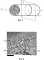
- the figure 1 represents a schematic view of the transverse sectional plane P illustrated by the figure 5 .
- the filter comprises or most often consists of a support element 1 made of a porous inorganic material which is preferably non-oxide.
- the element conventionally has a tubular shape, delimited by an external surface 2. It comprises in its internal portion 3 a set of adjacent channels 4, of axes parallel to each other and separated from each other by walls 8.
- the walls are made of a porous inorganic material allowing the filtrate to pass from the internal part 3 to the external surface 2.
- the channels 4 are covered on their internal surface with a separating membrane layer 5, as illustrated by the electron microscopy image shown on the figure 6 .
- This membrane separating layer 5 comes into contact with said fluid to be filtered flowing in said channels.
- the channels 4 of the structure 1 can be divided into different groups: All the internal channels Ci generally have a substantially equivalent hydraulic diameter and circular in shape (in section) and constitute the central part of the structure, within the meaning of the present invention.
- the filtering structure further comprises, around said central part, peripheral channels Cp occupying the outermost (or peripheral) ring of channels of the filter, said channels Cp sharing a common wall with the external surface 2.
- a minority part of the channels (denoted A) of the peripheral ring necessarily has a truncated shape, in order to maintain a sufficient thickness of the external wall.
- most of the other peripheral channels are circular in shape (B channels on the figure 1 ) identical to that of the channels Ci, the research carried out by the applicant company showed that the presence of these peripheral channels A of restricted hydraulic diameter, even in small number, had a negative and significant influence on the performance and efficiency of the filtration of the filter, as will be described later.
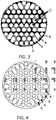
- the figures 2 and 3 illustrate different embodiments according to the invention of a tangential filter according to the invention, in which the structure also comprises a group G of two adjacent peripheral channels Cp A and B sharing a common wall (respectively 6 and 7 on the figure 2 ), with the external surface 2, which make it possible to solve such a problem.
- the filter according to figure 2 further comprises internal channels Ci of substantially equivalent hydraulic diameter and of circular shape (in section), which together constitute the central part of the structure, within the meaning of the present invention.
- the channels A are configured this time in such a way that their hydraulic diameter is greater than the hydraulic diameter of the channels B of circular section, the latter however being present in greater number on said peripheral ring.
- the filter according to figure 3 shows a configuration comprising three types of peripheral channels of different hydraulic diameter Dh.
- the number of circular peripheral channels B is greater than the number of adjacent channels with a higher Dh (A channels).
- the number of peripheral channels B of smaller Dh is lower than that of adjacent channels A of larger size.
- the figure 4 therefore illustrates a comparative embodiment in which the channels A of larger hydraulic diameter are this time in greater number than the channels B, contrary to the requirements of the present invention.
- the raw monoliths thus obtained are dried in a microwave for a time sufficient to bring the content of chemically unbound water to less than 1% by mass.
- the monoliths are then fired to a temperature of at least 2100 ° C which is maintained for 5 hours.
- the material obtained has an open porosity of 43% and an average pore distribution diameter of the order of 25 micrometers, as measured by mercury porosimetry.
- the slip is introduced into a tank with stirring (20 revolutions / min). After a phase of deaeration under a light vacuum (typically 25 millibars) while maintaining agitation, the tank is put under an overpressure of about 0.7 bar in order to be able to coat the inside of the support from its lower part up to at its upper end. This operation only takes a few seconds for a 30 cm long support. Immediately after coating the slip on the internal wall of the support channels, the excess is discharged by gravity.
- a light vacuum typically 25 millibars
- the supports are then dried at ambient temperature for 30 minutes then at 60 ° C. for 30 hours.
- the thus dried supports are then baked at a temperature above 1600 ° C.
- the baking temperature is a function of the characteristics required for the final porosity of the membrane, namely a median pore diameter of about 1 micrometer and an open porosity of 40%, by volume.
- a cross section is made on the filters thus obtained.
- the structure of the membrane is observed under a scanning microscope.
- On the figure 6 one of the electron microscopy images obtained has been reported.
- This figure shows the porous support 100 of high porosity, the primer layer 102 allowing the attachment of the membrane separating layer 103 of finer porosity.
- Table 1 we have reported the ratio of the average thickness of the membrane (103) thus measured on all the A channels to the average membrane thickness thus measured on all the B channels.
- a ratio close to 1 thus indicates an ideal repair of the inorganic filter material in all the filter channels.
- the further the ratio is from 1, the more heterogeneous the deposition of the membrane separating layer.
- the filtration area is calculated from the cumulative sum of the perimeters of all the channels of the structure.
- a flow measurement is carried out on the filters according to the following method.
- a fluid consisting of demineralized water and charged with 300 ppm of synthetic oil feeds the filters to be evaluated under a transmembrane pressure of 0.5 bars and a circulation speed in the channels of 2 m / s .
- the permeate (water) is collected at the periphery of the filter.
- the filter gradually clogs due to the deposition of oil in the channels on the surface of the separator membrane, resulting in a decrease in the quantity of permeate recovered at the periphery of the filter.
- the flow rate is measured after 20 hours of filtration.
- the characteristic flow rate measurement of the filter is expressed in L / min per meter of filter length after 20 hours of filtration.
- the throughput results have been expressed by reference to the data recorded for comparative Example 1. More precisely, a value greater than 100% indicates an increased flow rate compared to the reference and therefore an improvement in the filtration capacity.
- the filter according to Example 2 in fact shows an average thickness ratio of the membrane which is appreciably higher than for Example 1 as well as a very significantly higher filtrate flow rate after 20 hours of activity.
- the filter according to the embodiment of the invention illustrated by figure 3 also makes it possible to improve the homogeneity of deposition of the membrane while maintaining a permeate flow rate after 20 h which is substantially improved compared to the reference Example 1.
- the filter according to Example 4 is comparable with that of Example 3 (according to the invention), the sizes and geometries of the channels being similar. Contrary to the requirements of the present invention, the number of peripheral channels B (of smaller hydraulic diameter) according to the example / la figure 4 is however less than the number of peripheral channels of larger hydraulic diameter (channels A).
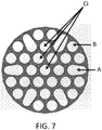
- FIG. 7 there is shown a view in cross section of another filter support according to the present invention, comprising a central part comprising only channels Ci of circular shape according to said section plane and peripheral channels A and B, the channel B having a section identical to that of the channels Ci and the channels A of larger hydraulic diameter, having a flared shape (ovoid), in the shape of a drop and the larger end of which is oriented towards the center of the filter .
- a configuration has been found to be particularly advantageous for maximizing the filtration surface area while maintaining a wall thickness between the channels A and B sufficient to maximize the permeate flow rate and obtain an acceptable ratio of the average thickness of the membranes, such as measured on channels A and channels B respectively.
Landscapes
- Engineering & Computer Science (AREA)
- Chemical & Material Sciences (AREA)
- General Engineering & Computer Science (AREA)
- Chemical Kinetics & Catalysis (AREA)
- Mechanical Engineering (AREA)
- Inorganic Chemistry (AREA)
- Life Sciences & Earth Sciences (AREA)
- Geology (AREA)
- Manufacturing & Machinery (AREA)
- Separation Using Semi-Permeable Membranes (AREA)
- Filtering Materials (AREA)
- Porous Artificial Stone Or Porous Ceramic Products (AREA)
Claims (15)
- Tangentialfilter zur Filtration eines Fluids, beispielsweise einer Flüssigkeit, umfassend oder bestehend aus einem Stützelement (1) aus einem porösen anorganischen Material, vorzugsweise Nichtoxid, wobei das Element eine rohrförmige Form aufweist, die durch eine Außenfläche (2) begrenzt ist, und umfassend in seinem Innenabschnitt (3) eine Reihe von benachbarten Kanälen (4) mit Achsen parallel zueinander, und durch Wände (8) des porösen anorganischen Materials voneinander getrennt, wobei die Kanäle (4) auf ihrer Innenfläche mit einer Membrantrennschicht (5) bedeckt sind, die ausgelegt ist, um mit dem zu filternden Fluid in Kontakt zu kommen, das in den Kanälen zirkuliert, dadurch gekennzeichnet, dass entlang einer Querebene P senkrecht zur Mittelachse der rohrförmigen Stütze:a) die Stütze in ihrem zentralem Teil nur Innenkanäle Ci umfasst, die keine gemeinsame Wand mit der Außenfläche teilen, wobei die Innenkanäle einen im Wesentlichen äquivalenten hydraulischen Durchmesser aufweisen,b) die Stütze ferner Umfangskanäle Cp, davon mindestens zwei benachbarte Umfangskanäle A und B umfasst, wobei jeder der zwei Kanäle A und B eine gemeinsame Wand (6, 7) mit der Außenfläche (2) teilt,c) das Verhältnis Dh zwischen:- dem hydraulischen Durchmesser DhA des ersten Kanals A und- dem hydraulischen Durchmesser DhB des zweiten Kanals B größer oder gleich 1,1 ist,d) die Anzahl der Umfangskanäle B größer oder gleich der Anzahl der Umfangskanäle A ist,e) der Kanal B einen hydraulischen Durchmesser DhB aufweist, der im Wesentlichen mit dem hydraulischen Durchmesser der Innenkanäle (Ci) identisch ist.
- Tangentialfilter nach dem vorhergehenden Anspruch, wobei der Kanal B mit kleinerem hydraulischen Durchmesser entlang der Querebene P eine Form aufweist, die im Wesentlichen mit derjenigen der Innenkanäle äquivalent ist.
- Tangentialfilter nach einem der vorhergehenden Ansprüche, wobei gemäß der Querebene P das Verhältnis Rs = SA/SB jeweils der Innenflächen SA und SB der Umfangskanäle A und B zwischen 1,1 und 3,5 liegt.
- Tangentialfilter nach einem der vorhergehenden Ansprüche, wobei gemäß der Querebene P die Innenkanäle (Ci) und vorzugsweise der Kanal B einen im Wesentlichen elliptischen Abschnitt aufweisen, wobei das Verhältnis zwischen der Hauptachse und der Nebenachse der Ellipse zwischen 2 und 1, vorzugsweise zwischen 1,5 und 1, und sehr bevorzugt zwischen 1,2 und 1 liegt.
- Tangentialfilter nach einem der vorhergehenden Ansprüche, wobei die Innenkanäle (Ci) entlang der Querebene P einen im Wesentlichen kreisförmigen Querschnitt aufweisen.
- Tangentialfilter nach einem der vorhergehenden Ansprüche, wobei der Kanal B gemäß der Querebene P einen im Wesentlichen kreisförmigen Querschnitt aufweist.
- Tangentialfilter nach einem der vorhergehenden Ansprüche, wobei der Kanal A eine aufgeweitete Form oder auch eine elliptische Form aufweist, und wobei sich seine Oberfläche gemäß der Querebene P hauptsächlich entlang einer Achse vom Umfang des Stützelements in Richtung seiner Mittelachse erstreckt.
- Tangentialfilter nach einem der vorhergehenden Ansprüche, wobei die Oberfläche der gemeinsamen Wand zwischen dem Kanal A und der Außenfläche gekrümmt ist.
- Tangentialfilter nach einem der vorhergehenden Ansprüche, wobei das Stützelement eine polygonale Basis oder kreisförmige Basis aufweist.
- Tangentialfilter nach einem der vorhergehenden Ansprüche, wobei mindestens ein Innenkanal Ci keine gemeinsame Wand mit einem Umfangskanal A teilt.
- Tangentialfilter nach einem der vorhergehenden Ansprüche, wobei das Stützelement in seinem Umfangsring nur Kanäle A und Kanäle B umfasst.
- Tangentialfilter nach einem der vorhergehenden Ansprüche, wobei die poröse Stütze ein Material, ausgewählt aus Siliciumcarbid, SiC, insbesondere gesintertem SiC in flüssiger Phase oder in fester Phase, rekristallisiertem SiC, Siliciumnitrid, insbesondere Si3N4, Siliciumoxynitrid, insbesondere Si2ON2, Silicium und Aluminiumoxynitrid oder eine Kombination davon umfasst.
- Tangentialfilter nach einem der vorhergehenden Ansprüche, wobei die Membrantrennschicht ein Keramikmaterial, vorzugsweise Nichtoxid, umfasst und vorzugsweise aus diesem besteht, vorzugsweise auch ausgewählt aus der Liste, bestehend aus Siliciumcarbid SiC, insbesondere gesintertem SiC in flüssiger oder fester Phase, oder rekristallisiertem SiC, Siliciumnitrid, insbesondere Si3N4, Siliciumoxynitrid, insbesondere Si2ON2, Silicium- und Aluminiumoxynitrid, Bornitrid BN oder eine Kombination davon.
- Tangentialfilter nach einem der vorhergehenden Ansprüche, wobei die Porosität des das Stützelement bildenden Materials zwischen 20 und 60 % liegt, der mittlere Porendurchmesser des die poröse Stütze bildenden Materials vorzugsweise zwischen 5 und 50 Mikrometer liegt.
- Tangentialfilter nach einem der vorhergehenden Ansprüche, wobei der äquivalente mittlere Porendurchmesser des Materials, das die Membrantrennschicht bildet, zwischen 1 nm und 5 Mikrometer liegt.
Applications Claiming Priority (2)
| Application Number | Priority Date | Filing Date | Title |
|---|---|---|---|
| FR1454637A FR3021231B1 (fr) | 2014-05-22 | 2014-05-22 | Filtres tangentiels |
| PCT/FR2015/051342 WO2015177476A1 (fr) | 2014-05-22 | 2015-05-21 | Filtre tangentiel avec un élément support comprenant un ensemble de canaux |
Publications (2)
| Publication Number | Publication Date |
|---|---|
| EP3145626A1 EP3145626A1 (de) | 2017-03-29 |
| EP3145626B1 true EP3145626B1 (de) | 2020-08-19 |
Family
ID=51417433
Family Applications (1)
| Application Number | Title | Priority Date | Filing Date |
|---|---|---|---|
| EP15732318.9A Active EP3145626B1 (de) | 2014-05-22 | 2015-05-21 | Tangentialfilter mit stützelement mit einer reihe von kanälen |
Country Status (10)
| Country | Link |
|---|---|
| US (1) | US10245561B2 (de) |
| EP (1) | EP3145626B1 (de) |
| JP (1) | JP6636951B2 (de) |
| KR (1) | KR102358966B1 (de) |
| CN (2) | CN106457086A (de) |
| BR (1) | BR112016027032B1 (de) |
| CA (1) | CA2947124C (de) |
| DK (1) | DK3145626T3 (de) |
| FR (1) | FR3021231B1 (de) |
| WO (1) | WO2015177476A1 (de) |
Families Citing this family (6)
| Publication number | Priority date | Publication date | Assignee | Title |
|---|---|---|---|---|
| DE102014211395B3 (de) * | 2014-06-13 | 2015-06-25 | Danfoss Power Solutions Gmbh & Co. Ohg | Hydraulikflüssigkeitssiebelement |
| FR3045398A1 (fr) * | 2015-12-18 | 2017-06-23 | Saint-Gobain Centre De Rech Et D'Etudes Europeen | Filtre monolithique |
| FR3060410B1 (fr) * | 2016-12-21 | 2019-05-24 | Technologies Avancees Et Membranes Industrielles | Element de separation par flux tangentiel integrant des canaux flexueux |
| FR3066924B1 (fr) * | 2017-05-31 | 2019-07-12 | Saint-Gobain Centre De Recherches Et D'etudes Europeen | Structure filtrante a membrane |
| FR3074060B1 (fr) * | 2017-11-30 | 2023-04-28 | Saint Gobain Ct Recherches | Structure filtrante membranaire monolithique |
| CN115957630A (zh) * | 2021-10-12 | 2023-04-14 | 三达膜科技(厦门)有限公司 | 一种多通道管式陶瓷膜支撑体 |
Family Cites Families (15)
| Publication number | Priority date | Publication date | Assignee | Title |
|---|---|---|---|---|
| DE4134223C1 (de) | 1991-10-16 | 1992-11-12 | Stora Feldmuehle Ag, 4000 Duesseldorf, De | |
| FR2720953B1 (fr) | 1994-06-08 | 1996-08-30 | Tami Ind | Elément inorganique multicanal pour la filtration d'un fluide. |
| FR2741821B1 (fr) * | 1995-12-05 | 1998-02-20 | Tami Ind | Element tubulaire inorganique de filtration presentant une surface de filtration et une resistance mecanique accrues |
| FR2741822B1 (fr) | 1995-12-05 | 1998-02-20 | Tami Ind | Element tubulaire inorganique de filtration comportant des canaux de section non circulaire presentant des profils optimises |
| US5641332A (en) | 1995-12-20 | 1997-06-24 | Corning Incorporated | Filtraion device with variable thickness walls |
| EP0787524B1 (de) * | 1996-01-31 | 2002-08-14 | Corning Incorporated | Filter und dessen Verwendung |
| US6077436A (en) * | 1997-01-06 | 2000-06-20 | Corning Incorporated | Device for altering a feed stock and method for using same |
| FR2785831B1 (fr) | 1998-11-18 | 2001-11-23 | Orelis | Support monolithe poreux d'un element de filtration et element de filtration |
| DE19854319A1 (de) * | 1998-11-25 | 2000-05-31 | Hermsdorfer Inst Tech Keramik | Fiterelement |
| FR2805331B1 (fr) | 2000-02-21 | 2002-05-31 | Ceramiques Tech Soc D | Element multicanal et procede de fabrication d'un tel element |
| DE10061126C1 (de) * | 2000-12-07 | 2002-01-24 | Aaflowsystems Gmbh & Co Kg | Verfahren zur Herstellung eines Membranmoduls |
| DE10160855A1 (de) * | 2001-12-12 | 2003-06-26 | Schumacher Umwelt Trenntech | Filterelement und Filtervorrichtung für die Cross-Flow-Filtration |
| DE10331049B4 (de) * | 2003-07-09 | 2010-04-08 | Saint-Gobain Industriekeramik Rödental GmbH | Verfahren zur Herstellung eines porösen Keramikkörpers, danach hergestellter poröser Keramikkörper und dessen Verwendung |
| FR2876922B1 (fr) * | 2004-10-27 | 2007-01-12 | Orelis Sa | Support monolithe poreux d'un element de filtration |
| FR2958288B1 (fr) * | 2010-04-01 | 2012-10-05 | Saint Gobain Ct Recherches | Materiau a pores tubulaires |
-
2014
- 2014-05-22 FR FR1454637A patent/FR3021231B1/fr not_active Expired - Fee Related
-
2015
- 2015-05-21 KR KR1020167032279A patent/KR102358966B1/ko active Active
- 2015-05-21 CN CN201580026432.2A patent/CN106457086A/zh active Pending
- 2015-05-21 US US15/312,997 patent/US10245561B2/en active Active
- 2015-05-21 JP JP2016568930A patent/JP6636951B2/ja active Active
- 2015-05-21 EP EP15732318.9A patent/EP3145626B1/de active Active
- 2015-05-21 CN CN202210458627.6A patent/CN114984761A/zh active Pending
- 2015-05-21 CA CA2947124A patent/CA2947124C/fr active Active
- 2015-05-21 DK DK15732318.9T patent/DK3145626T3/da active
- 2015-05-21 WO PCT/FR2015/051342 patent/WO2015177476A1/fr not_active Ceased
- 2015-05-21 BR BR112016027032-0A patent/BR112016027032B1/pt active IP Right Grant
Non-Patent Citations (1)
| Title |
|---|
| None * |
Also Published As
| Publication number | Publication date |
|---|---|
| WO2015177476A1 (fr) | 2015-11-26 |
| CN106457086A (zh) | 2017-02-22 |
| BR112016027032A2 (de) | 2017-08-15 |
| US10245561B2 (en) | 2019-04-02 |
| BR112016027032B1 (pt) | 2022-02-15 |
| US20170182468A1 (en) | 2017-06-29 |
| KR20170005817A (ko) | 2017-01-16 |
| JP2017521235A (ja) | 2017-08-03 |
| CA2947124C (fr) | 2022-10-25 |
| FR3021231B1 (fr) | 2018-02-16 |
| DK3145626T3 (da) | 2020-11-16 |
| CN114984761A (zh) | 2022-09-02 |
| EP3145626A1 (de) | 2017-03-29 |
| FR3021231A1 (fr) | 2015-11-27 |
| KR102358966B1 (ko) | 2022-02-08 |
| JP6636951B2 (ja) | 2020-01-29 |
| CA2947124A1 (fr) | 2015-11-26 |
Similar Documents
| Publication | Publication Date | Title |
|---|---|---|
| CA2947124C (fr) | Filtre tangentiel avec un element support comprenant un ensemble de canaux | |
| EP3233252B1 (de) | Filter mit sic-membranen mit stickstoff | |
| EP3999217B1 (de) | Filter mit einer silikoncarbid-separatorschicht | |
| EP3288669A1 (de) | Montierte filter zum filtrieren von flüssigkeiten | |
| EP3233253B1 (de) | Filter mit sauerstoffarmen sic-membranen | |
| WO2017220907A1 (fr) | Filtres comprenant des couches separatrices a base de beta-sic | |
| CA2969061A1 (fr) | Filtres a membranes composites sic-nitrure ou sic-oxynitrure | |
| EP2285753A1 (de) | Katalytisches filter oder substrat, enthaltend siliciumcarbid und aluminiumtitanat | |
| EP3389833A1 (de) | Monolithischer filter | |
| EP3717106B1 (de) | Monolithische membranfiltrationsstruktur | |
| FR3066924B1 (fr) | Structure filtrante a membrane | |
| EP3887025A1 (de) | Dynamische filtervorrichtung mit poröser keramischer siliciumcarbidplatte |
Legal Events
| Date | Code | Title | Description |
|---|---|---|---|
| STAA | Information on the status of an ep patent application or granted ep patent |
Free format text: STATUS: THE INTERNATIONAL PUBLICATION HAS BEEN MADE |
|
| PUAI | Public reference made under article 153(3) epc to a published international application that has entered the european phase |
Free format text: ORIGINAL CODE: 0009012 |
|
| STAA | Information on the status of an ep patent application or granted ep patent |
Free format text: STATUS: REQUEST FOR EXAMINATION WAS MADE |
|
| 17P | Request for examination filed |
Effective date: 20161222 |
|
| AK | Designated contracting states |
Kind code of ref document: A1 Designated state(s): AL AT BE BG CH CY CZ DE DK EE ES FI FR GB GR HR HU IE IS IT LI LT LU LV MC MK MT NL NO PL PT RO RS SE SI SK SM TR |
|
| AX | Request for extension of the european patent |
Extension state: BA ME |
|
| DAV | Request for validation of the european patent (deleted) | ||
| DAX | Request for extension of the european patent (deleted) | ||
| GRAP | Despatch of communication of intention to grant a patent |
Free format text: ORIGINAL CODE: EPIDOSNIGR1 |
|
| STAA | Information on the status of an ep patent application or granted ep patent |
Free format text: STATUS: GRANT OF PATENT IS INTENDED |
|
| INTG | Intention to grant announced |
Effective date: 20200312 |
|
| RAP1 | Party data changed (applicant data changed or rights of an application transferred) |
Owner name: SAINT-GOBAIN CENTRE DE RECHERCHES ET D'ETUDES EUROPEEN |
|
| GRAS | Grant fee paid |
Free format text: ORIGINAL CODE: EPIDOSNIGR3 |
|
| GRAA | (expected) grant |
Free format text: ORIGINAL CODE: 0009210 |
|
| STAA | Information on the status of an ep patent application or granted ep patent |
Free format text: STATUS: THE PATENT HAS BEEN GRANTED |
|
| AK | Designated contracting states |
Kind code of ref document: B1 Designated state(s): AL AT BE BG CH CY CZ DE DK EE ES FI FR GB GR HR HU IE IS IT LI LT LU LV MC MK MT NL NO PL PT RO RS SE SI SK SM TR |
|
| REG | Reference to a national code |
Ref country code: CH Ref legal event code: EP |
|
| REG | Reference to a national code |
Ref country code: DE Ref legal event code: R096 Ref document number: 602015057679 Country of ref document: DE |
|
| REG | Reference to a national code |
Ref country code: AT Ref legal event code: REF Ref document number: 1303314 Country of ref document: AT Kind code of ref document: T Effective date: 20200915 |
|
| REG | Reference to a national code |
Ref country code: IE Ref legal event code: FG4D Free format text: LANGUAGE OF EP DOCUMENT: FRENCH |
|
| REG | Reference to a national code |
Ref country code: DK Ref legal event code: T3 Effective date: 20201109 |
|
| REG | Reference to a national code |
Ref country code: LT Ref legal event code: MG4D |
|
| REG | Reference to a national code |
Ref country code: NL Ref legal event code: MP Effective date: 20200819 |
|
| PG25 | Lapsed in a contracting state [announced via postgrant information from national office to epo] |
Ref country code: NO Free format text: LAPSE BECAUSE OF FAILURE TO SUBMIT A TRANSLATION OF THE DESCRIPTION OR TO PAY THE FEE WITHIN THE PRESCRIBED TIME-LIMIT Effective date: 20201119 Ref country code: FI Free format text: LAPSE BECAUSE OF FAILURE TO SUBMIT A TRANSLATION OF THE DESCRIPTION OR TO PAY THE FEE WITHIN THE PRESCRIBED TIME-LIMIT Effective date: 20200819 Ref country code: HR Free format text: LAPSE BECAUSE OF FAILURE TO SUBMIT A TRANSLATION OF THE DESCRIPTION OR TO PAY THE FEE WITHIN THE PRESCRIBED TIME-LIMIT Effective date: 20200819 Ref country code: LT Free format text: LAPSE BECAUSE OF FAILURE TO SUBMIT A TRANSLATION OF THE DESCRIPTION OR TO PAY THE FEE WITHIN THE PRESCRIBED TIME-LIMIT Effective date: 20200819 Ref country code: PT Free format text: LAPSE BECAUSE OF FAILURE TO SUBMIT A TRANSLATION OF THE DESCRIPTION OR TO PAY THE FEE WITHIN THE PRESCRIBED TIME-LIMIT Effective date: 20201221 Ref country code: SE Free format text: LAPSE BECAUSE OF FAILURE TO SUBMIT A TRANSLATION OF THE DESCRIPTION OR TO PAY THE FEE WITHIN THE PRESCRIBED TIME-LIMIT Effective date: 20200819 Ref country code: BG Free format text: LAPSE BECAUSE OF FAILURE TO SUBMIT A TRANSLATION OF THE DESCRIPTION OR TO PAY THE FEE WITHIN THE PRESCRIBED TIME-LIMIT Effective date: 20201119 Ref country code: GR Free format text: LAPSE BECAUSE OF FAILURE TO SUBMIT A TRANSLATION OF THE DESCRIPTION OR TO PAY THE FEE WITHIN THE PRESCRIBED TIME-LIMIT Effective date: 20201120 |
|
| REG | Reference to a national code |
Ref country code: AT Ref legal event code: MK05 Ref document number: 1303314 Country of ref document: AT Kind code of ref document: T Effective date: 20200819 |
|
| PG25 | Lapsed in a contracting state [announced via postgrant information from national office to epo] |
Ref country code: PL Free format text: LAPSE BECAUSE OF FAILURE TO SUBMIT A TRANSLATION OF THE DESCRIPTION OR TO PAY THE FEE WITHIN THE PRESCRIBED TIME-LIMIT Effective date: 20200819 Ref country code: NL Free format text: LAPSE BECAUSE OF FAILURE TO SUBMIT A TRANSLATION OF THE DESCRIPTION OR TO PAY THE FEE WITHIN THE PRESCRIBED TIME-LIMIT Effective date: 20200819 Ref country code: RS Free format text: LAPSE BECAUSE OF FAILURE TO SUBMIT A TRANSLATION OF THE DESCRIPTION OR TO PAY THE FEE WITHIN THE PRESCRIBED TIME-LIMIT Effective date: 20200819 Ref country code: LV Free format text: LAPSE BECAUSE OF FAILURE TO SUBMIT A TRANSLATION OF THE DESCRIPTION OR TO PAY THE FEE WITHIN THE PRESCRIBED TIME-LIMIT Effective date: 20200819 Ref country code: IS Free format text: LAPSE BECAUSE OF FAILURE TO SUBMIT A TRANSLATION OF THE DESCRIPTION OR TO PAY THE FEE WITHIN THE PRESCRIBED TIME-LIMIT Effective date: 20201219 |
|
| PG25 | Lapsed in a contracting state [announced via postgrant information from national office to epo] |
Ref country code: CZ Free format text: LAPSE BECAUSE OF FAILURE TO SUBMIT A TRANSLATION OF THE DESCRIPTION OR TO PAY THE FEE WITHIN THE PRESCRIBED TIME-LIMIT Effective date: 20200819 Ref country code: EE Free format text: LAPSE BECAUSE OF FAILURE TO SUBMIT A TRANSLATION OF THE DESCRIPTION OR TO PAY THE FEE WITHIN THE PRESCRIBED TIME-LIMIT Effective date: 20200819 Ref country code: RO Free format text: LAPSE BECAUSE OF FAILURE TO SUBMIT A TRANSLATION OF THE DESCRIPTION OR TO PAY THE FEE WITHIN THE PRESCRIBED TIME-LIMIT Effective date: 20200819 Ref country code: SM Free format text: LAPSE BECAUSE OF FAILURE TO SUBMIT A TRANSLATION OF THE DESCRIPTION OR TO PAY THE FEE WITHIN THE PRESCRIBED TIME-LIMIT Effective date: 20200819 |
|
| REG | Reference to a national code |
Ref country code: DE Ref legal event code: R097 Ref document number: 602015057679 Country of ref document: DE |
|
| PG25 | Lapsed in a contracting state [announced via postgrant information from national office to epo] |
Ref country code: AT Free format text: LAPSE BECAUSE OF FAILURE TO SUBMIT A TRANSLATION OF THE DESCRIPTION OR TO PAY THE FEE WITHIN THE PRESCRIBED TIME-LIMIT Effective date: 20200819 Ref country code: AL Free format text: LAPSE BECAUSE OF FAILURE TO SUBMIT A TRANSLATION OF THE DESCRIPTION OR TO PAY THE FEE WITHIN THE PRESCRIBED TIME-LIMIT Effective date: 20200819 Ref country code: ES Free format text: LAPSE BECAUSE OF FAILURE TO SUBMIT A TRANSLATION OF THE DESCRIPTION OR TO PAY THE FEE WITHIN THE PRESCRIBED TIME-LIMIT Effective date: 20200819 |
|
| PLBE | No opposition filed within time limit |
Free format text: ORIGINAL CODE: 0009261 |
|
| STAA | Information on the status of an ep patent application or granted ep patent |
Free format text: STATUS: NO OPPOSITION FILED WITHIN TIME LIMIT |
|
| PG25 | Lapsed in a contracting state [announced via postgrant information from national office to epo] |
Ref country code: SK Free format text: LAPSE BECAUSE OF FAILURE TO SUBMIT A TRANSLATION OF THE DESCRIPTION OR TO PAY THE FEE WITHIN THE PRESCRIBED TIME-LIMIT Effective date: 20200819 |
|
| 26N | No opposition filed |
Effective date: 20210520 |
|
| PG25 | Lapsed in a contracting state [announced via postgrant information from national office to epo] |
Ref country code: SI Free format text: LAPSE BECAUSE OF FAILURE TO SUBMIT A TRANSLATION OF THE DESCRIPTION OR TO PAY THE FEE WITHIN THE PRESCRIBED TIME-LIMIT Effective date: 20200819 |
|
| REG | Reference to a national code |
Ref country code: CH Ref legal event code: PL |
|
| GBPC | Gb: european patent ceased through non-payment of renewal fee |
Effective date: 20210521 |
|
| PG25 | Lapsed in a contracting state [announced via postgrant information from national office to epo] |
Ref country code: LU Free format text: LAPSE BECAUSE OF NON-PAYMENT OF DUE FEES Effective date: 20210521 Ref country code: MC Free format text: LAPSE BECAUSE OF FAILURE TO SUBMIT A TRANSLATION OF THE DESCRIPTION OR TO PAY THE FEE WITHIN THE PRESCRIBED TIME-LIMIT Effective date: 20200819 Ref country code: LI Free format text: LAPSE BECAUSE OF NON-PAYMENT OF DUE FEES Effective date: 20210531 Ref country code: CH Free format text: LAPSE BECAUSE OF NON-PAYMENT OF DUE FEES Effective date: 20210531 |
|
| REG | Reference to a national code |
Ref country code: BE Ref legal event code: MM Effective date: 20210531 |
|
| PG25 | Lapsed in a contracting state [announced via postgrant information from national office to epo] |
Ref country code: IE Free format text: LAPSE BECAUSE OF NON-PAYMENT OF DUE FEES Effective date: 20210521 Ref country code: GB Free format text: LAPSE BECAUSE OF NON-PAYMENT OF DUE FEES Effective date: 20210521 |
|
| PG25 | Lapsed in a contracting state [announced via postgrant information from national office to epo] |
Ref country code: BE Free format text: LAPSE BECAUSE OF NON-PAYMENT OF DUE FEES Effective date: 20210531 |
|
| PG25 | Lapsed in a contracting state [announced via postgrant information from national office to epo] |
Ref country code: HU Free format text: LAPSE BECAUSE OF FAILURE TO SUBMIT A TRANSLATION OF THE DESCRIPTION OR TO PAY THE FEE WITHIN THE PRESCRIBED TIME-LIMIT; INVALID AB INITIO Effective date: 20150521 |
|
| PG25 | Lapsed in a contracting state [announced via postgrant information from national office to epo] |
Ref country code: CY Free format text: LAPSE BECAUSE OF FAILURE TO SUBMIT A TRANSLATION OF THE DESCRIPTION OR TO PAY THE FEE WITHIN THE PRESCRIBED TIME-LIMIT Effective date: 20200819 |
|
| PG25 | Lapsed in a contracting state [announced via postgrant information from national office to epo] |
Ref country code: MK Free format text: LAPSE BECAUSE OF FAILURE TO SUBMIT A TRANSLATION OF THE DESCRIPTION OR TO PAY THE FEE WITHIN THE PRESCRIBED TIME-LIMIT Effective date: 20200819 |
|
| PG25 | Lapsed in a contracting state [announced via postgrant information from national office to epo] |
Ref country code: MT Free format text: LAPSE BECAUSE OF FAILURE TO SUBMIT A TRANSLATION OF THE DESCRIPTION OR TO PAY THE FEE WITHIN THE PRESCRIBED TIME-LIMIT Effective date: 20200819 |
|
| PGFP | Annual fee paid to national office [announced via postgrant information from national office to epo] |
Ref country code: DE Payment date: 20250402 Year of fee payment: 11 |
|
| PGFP | Annual fee paid to national office [announced via postgrant information from national office to epo] |
Ref country code: DK Payment date: 20250516 Year of fee payment: 11 |
|
| PGFP | Annual fee paid to national office [announced via postgrant information from national office to epo] |
Ref country code: IT Payment date: 20250422 Year of fee payment: 11 |
|
| PGFP | Annual fee paid to national office [announced via postgrant information from national office to epo] |
Ref country code: FR Payment date: 20250401 Year of fee payment: 11 |
|
| PG25 | Lapsed in a contracting state [announced via postgrant information from national office to epo] |
Ref country code: TR Free format text: LAPSE BECAUSE OF FAILURE TO SUBMIT A TRANSLATION OF THE DESCRIPTION OR TO PAY THE FEE WITHIN THE PRESCRIBED TIME-LIMIT Effective date: 20200819 |