EP3145466B2 - Rollen zur herstellung von befestigungsschellen - Google Patents
Rollen zur herstellung von befestigungsschellen Download PDFInfo
- Publication number
- EP3145466B2 EP3145466B2 EP15727768.2A EP15727768A EP3145466B2 EP 3145466 B2 EP3145466 B2 EP 3145466B2 EP 15727768 A EP15727768 A EP 15727768A EP 3145466 B2 EP3145466 B2 EP 3145466B2
- Authority
- EP
- European Patent Office
- Prior art keywords
- roll
- fastening
- elongated material
- width
- longitudinal edge
- Prior art date
- Legal status (The legal status is an assumption and is not a legal conclusion. Google has not performed a legal analysis and makes no representation as to the accuracy of the status listed.)
- Active
Links
Images

Classifications
-
- A—HUMAN NECESSITIES
- A44—HABERDASHERY; JEWELLERY
- A44B—BUTTONS, PINS, BUCKLES, SLIDE FASTENERS, OR THE LIKE
- A44B18/00—Fasteners of the touch-and-close type; Making such fasteners
- A44B18/0003—Fastener constructions
- A44B18/0015—Male or hook elements
-
- A—HUMAN NECESSITIES
- A44—HABERDASHERY; JEWELLERY
- A44B—BUTTONS, PINS, BUCKLES, SLIDE FASTENERS, OR THE LIKE
- A44B18/00—Fasteners of the touch-and-close type; Making such fasteners
- A44B18/0003—Fastener constructions
- A44B18/0015—Male or hook elements
- A44B18/0019—Male or hook elements of a mushroom type
-
- A—HUMAN NECESSITIES
- A44—HABERDASHERY; JEWELLERY
- A44B—BUTTONS, PINS, BUCKLES, SLIDE FASTENERS, OR THE LIKE
- A44B18/00—Fasteners of the touch-and-close type; Making such fasteners
- A44B18/0069—Details
- A44B18/0073—Attaching means
-
- A—HUMAN NECESSITIES
- A61—MEDICAL OR VETERINARY SCIENCE; HYGIENE
- A61F—FILTERS IMPLANTABLE INTO BLOOD VESSELS; PROSTHESES; DEVICES PROVIDING PATENCY TO, OR PREVENTING COLLAPSING OF, TUBULAR STRUCTURES OF THE BODY, e.g. STENTS; ORTHOPAEDIC, NURSING OR CONTRACEPTIVE DEVICES; FOMENTATION; TREATMENT OR PROTECTION OF EYES OR EARS; BANDAGES, DRESSINGS OR ABSORBENT PADS; FIRST-AID KITS
- A61F13/00—Bandages or dressings; Absorbent pads
- A61F13/15—Absorbent pads, e.g. sanitary towels, swabs or tampons for external or internal application to the body; Supporting or fastening means therefor; Tampon applicators
- A61F13/15577—Apparatus or processes for manufacturing
- A61F13/15756—Applying tabs, strips, tapes, loops; Knotting the ends of pads
-
- A—HUMAN NECESSITIES
- A61—MEDICAL OR VETERINARY SCIENCE; HYGIENE
- A61F—FILTERS IMPLANTABLE INTO BLOOD VESSELS; PROSTHESES; DEVICES PROVIDING PATENCY TO, OR PREVENTING COLLAPSING OF, TUBULAR STRUCTURES OF THE BODY, e.g. STENTS; ORTHOPAEDIC, NURSING OR CONTRACEPTIVE DEVICES; FOMENTATION; TREATMENT OR PROTECTION OF EYES OR EARS; BANDAGES, DRESSINGS OR ABSORBENT PADS; FIRST-AID KITS
- A61F13/00—Bandages or dressings; Absorbent pads
- A61F13/15—Absorbent pads, e.g. sanitary towels, swabs or tampons for external or internal application to the body; Supporting or fastening means therefor; Tampon applicators
- A61F13/56—Supporting or fastening means
- A61F13/58—Adhesive tab fastener elements
- A61F13/581—Tab fastener elements combining adhesive and mechanical fastening
-
- A—HUMAN NECESSITIES
- A61—MEDICAL OR VETERINARY SCIENCE; HYGIENE
- A61F—FILTERS IMPLANTABLE INTO BLOOD VESSELS; PROSTHESES; DEVICES PROVIDING PATENCY TO, OR PREVENTING COLLAPSING OF, TUBULAR STRUCTURES OF THE BODY, e.g. STENTS; ORTHOPAEDIC, NURSING OR CONTRACEPTIVE DEVICES; FOMENTATION; TREATMENT OR PROTECTION OF EYES OR EARS; BANDAGES, DRESSINGS OR ABSORBENT PADS; FIRST-AID KITS
- A61F13/00—Bandages or dressings; Absorbent pads
- A61F13/15—Absorbent pads, e.g. sanitary towels, swabs or tampons for external or internal application to the body; Supporting or fastening means therefor; Tampon applicators
- A61F13/56—Supporting or fastening means
- A61F13/62—Mechanical fastening means ; Fabric strip fastener elements, e.g. hook and loop
- A61F13/622—Fabric strip fastener elements, e.g. hook and loop
- A61F13/625—Fabric strip fastener elements, e.g. hook and loop characterised by the hook
-
- A—HUMAN NECESSITIES
- A44—HABERDASHERY; JEWELLERY
- A44B—BUTTONS, PINS, BUCKLES, SLIDE FASTENERS, OR THE LIKE
- A44B18/00—Fasteners of the touch-and-close type; Making such fasteners
- A44B18/0046—Fasteners made integrally of plastics
-
- A—HUMAN NECESSITIES
- A44—HABERDASHERY; JEWELLERY
- A44B—BUTTONS, PINS, BUCKLES, SLIDE FASTENERS, OR THE LIKE
- A44B18/00—Fasteners of the touch-and-close type; Making such fasteners
- A44B18/0069—Details
Definitions
- the present invention relates to rolls of an elongated material for manufacture of fastening tabs as well as to methods of manufacturing fastening tabs.
- Fastening tabs are widely used in hygiene industry.
- One important application of such fastening tabs relates to the closure system of diapers.
- These fastening tabs comprise a substrate having a manufacturer's end typically including an adhesive for attaching a tab to a disposable article, e.g., to the outer side of a diaper's ear, and an opposite user's end which may be gripped by a user and attached to a landing zone of, e.g., the diaper.
- the user's end typically comprises a mechanical fastening material, such as a hook material for releasably attaching the fastening tab to e.g.
- fastening tabs are typically provided in large rolls of an elongated endless material, from which individual tabs are cut. Such fastening tabs are often provided on so-called twin rolls in the form of a planetary roll.
- the elongated material of such a twin roll comprises, along the cross or width direction, two adjacent fastening tabs, which are separated from one another through a center line of the elongated material.
- the user's ends typically comprising the fastening material and the narrow finger lift
- the finger lift areas being adjacent to one another along the center line
- the manufacturer's ends are provided at the outer regions of the elongated material, where adhesive then is applied near but spaced apart ( ⁇ 2-3 mm) from the edges.
- the adhesive is applied away from the edge of the manufacturer's end, because during processing the web typically shakes in the cross direction along its path thus necessitating the positioning of the adhesive applicator head inwardly away from the edge.
- twin rolls according to the prior art have various disadvantages.
- the cross dimension of the elongated material (-90 mm) is much lower than the diameter of the roll (which may be up about 1 m) and since the thickest portion of the elongated material i.e., the mechanical fastening elements in the user's ends is provided towards the center of the elongated material with the low profile manufacturer's ends to the outer regions, these twin rolls exhibit roll instability.
- the non-adherent part of the manufacturer's end protrudes from the final product like a flap and may create sharp edges or corners.
- a twin roll of an elongated material where the mechanical fastening elements are provided in the two outer longitudinal edge portions (each being at most 30% of the total width of the elongated material) and where on the same side at least the innermost central region (which for example may have a width up to 30% of the total width of the elongated material) of the central portion is free of said fastening elements so that such portion or at least a part of such portion thereof can be used to affix tab(s) obtained from such roll to absorbent article(s) (and thus accordingly the opposite side is free of adhesive), it is possible to provide a twin roll having improved roll stability and resistance to penetration of dirt and dust into the roll.
- the fastening elements i.e. the thickest portions of the elongated material, are provided in the two outer edge portions at or close to the edges of the roll, thus facilitating roll stability and acting as a barrier helping to prevent or reduce ingress of dust and dirt particles into the roll.
- a roll of an elongated material for manufacture of fastening tabs comprising first and second major surfaces, two longitudinal edge portions and a central portion provided in the width direction in between the two longitudinal edge portions, the width of each longitudinal edge portion being at most 30% of the total width of the elongated material, wherein each of the two longitudinal edge portions has fastening elements provided on at least a region of the first major surface, wherein the central portion comprises an innermost central region, the first major surface of the innermost central region being free of fastening elements, and wherein the second major surface is free of adhesive.
- twin rolls having longer roll lengths (and thus higher roll diameters) and/or more narrow cross-widths is advantageously possible.
- the width of the manufacturer's end can be easily lengthened as needed and/or desired without immediately, detrimentally impacting roll stability.
- the use of a longer manufacturer's end and thus overall longer fastening tab in conjunction with a landing zone on e.g. a diaper or incontinence brief can be useful in providing a wider range of sizing.
- the width of the innermost central region in the central portion may be up to 30% of the total width of the elongated material, in particular ranging from about 7% to about 30% (inclusive) of the total width of the elongated material.
- each longitudinal edge portion is at least 13% of the total width of the elongated material.
- Each of the longitudinal edge portions may comprise an outermost edge region whose first major surface is free of fastening elements. Once a fastening tab has been cut from the roll of elongated material, such an outermost edge region provides a so-called finger lift to the user.
- the width of each of the outermost edge regions is preferably in the range between 3% and 10% (inclusive) of the total width of the elongated material. Preferably, the width of each of the edge regions is in the range between 3 mm and 12 mm (inclusive), more preferably between 5 mm and 9 mm (inclusive).
- each of the longitudinal edge portions comprises a fastening region with the fastening elements of the longitudinal edge portions being provided on the first major surface of each of said fastening regions.
- the width of each of the fastening regions is preferably in the range between 3% and 30% (inclusive), more preferably between 10% and 27% (inclusive) of the total width of the elongated material.
- the width of each of the fastening regions is in the range between 10 mm and 30 mm (inclusive), more preferably between 13 mm and 25 mm (inclusive).
- the first major surface in the entire central portion is free of fastening elements.
- the elongated material is a laminate comprising a carrier web extending over substantially the total width of the elongated material and a fastening material comprising a plurality of fastening elements.
- each longitudinal edge portion is provided with at least one elongate strip of the fastening material.
- the at least one elongate strip of the fastening material in each longitudinal edge portion may be directly or indirectly affixed to the carrier web via, e.g., adhesive, ultrasonic welding, and/or hot-air welding or in-situ lamination (e.g. where the elongate strip of the fastening material is extruded directly onto the carrier).
- the carrier of the laminate preferably comprises a nonwoven.
- the fastening elements may comprise male fastening elements, which are preferably selected from the group consisting of hook fasteners, mushroom-shaped fasteners, stem-shaped fasteners, cup-shaped fasteners, T-shaped fasteners and mixtures thereof.
- Twin rolls described herein are particular suited for in line processing towards affixing tabs onto absorbent articles or precursor materials for absorbent articles.
- first major surface of the innermost central region of the central portion of the rolled elongated material may be provided with adhesive, it is favorable to provide rolls wherein the first major surface of the innermost central region of the central portion is free of adhesive. This is advantageous in that such embodiments would not require a polycoat, and more particularly the means used for affixing the manufacturer's end can be selected as desired and/or needed at the time of the manufacture fastening tabs and their attachment to absorbent articles or precursor materials.
- the first major surface of the central portion outside the innermost central region, in particular just adjacent to the two longitudinal edge portions may include adhesive to provide for fastening tabs including a so-called "anti-flagging feature".
- Another aspect of the present invention is a method of manufacturing fastening tabs, the method comprising the following steps:
- twin rolls with the user's ends in the middle, after slitting and cutting, the generated pair of tabs need to be either flipped or rotated to bring them in the right orientation to one another for attachment to an absorbent article such as a diaper or an incontinence brief. Accordingly twin rolls and such methods described herein are also advantageous in that in-line-handling is easier.
- Methods described herein preferably comprise the step of affixing at least one of the fastening tabs at its manufacturer's end to an absorbent article or to an absorbent article precursor material.
- the step of affixing may comprise one or a combination of ultrasound welding, hot-air welding and adhesive bonding.
- the step of affixing is preferably performed essentially at the same time or after the step of cutting each of the two elongated strips in the cross direction.
- the method comprises the step of applying an adhesive onto the first major surface of at least a part of the innermost central region of the central portion between unwinding and slitting the elongated material along its length through the innermost central region of the central portion and cutting each of the two elongated strips in the cross direction.
- Adhesive may be applied to the entire innermost central region or just a part (e.g. a major part) of the innermost central region.
- the adhesive is applied such that the step of slitting the elongated material along its length through the innermost central region of the central portion comprises slitting through the adhesive provided on the first major surface of the innermost central region.
- each of the two sections of the central portion obtained after slitting has adhesive in the region along and adjacent to the cut edge.
- the method may further comprise the step of affixing at least one of the fastening tabs at its manufacturer's end to an absorbent article or to an absorbent article precursor material using the adhesive applied onto the first major surface of the innermost central region of the central portion.
- the step of affixing is performed essentially at the same time or after the step of cutting each of the two elongated strips in the cross direction.
- the respective portion of the manufacturer's end of the final fastening tab is fully covered with adhesive all the way to its cut edge.
- the manufacturer's end of the final fastening tab will nicely adhere to the absorbent article or the absorbent article precursor without any loose edges or flaps protruding from the absorbent article or the absorbent article precursor material.
- Figure 3 shows a schematic perspective view of an exemplary embodiment of a roll 1 of an elongated material 2 according to the present invention while Figure 1 shows a schematic cross-section of a single layer of the elongated material and Figure 2 shows a schematic, partial cross-section through a number of layers of the elongated material arranged on the roll.
- the exemplary roll is a planetary roll.
- the elongated material 2 includes a carrier web 2a extending over substantially the total width of the elongated material and comprises a first major surface 3 and a second major surface 4, two longitudinal edge portions 5a and 5b and a central portion 6 provided in the width direction in between the longitudinal edge portions 5a and 5b.
- Each of the two longitudinal edge portions 5a and 5b has mechanical fastening elements 8 provided on at least a region of the first major surface 3.
- the width of each longitudinal edge portion 5a, 5b is at most 30% of the total width of the elongated material 2.
- each of the longitudinal edge portions 5a and 5b comprises an outermost edge region 7a and 7b, respectively, whose first major surface 3 is free of fastening elements.
- outermost edge regions 7a and 7b may be used as a finger lift in the final fastening tab.
- the remaining regions of the longitudinal edge portions 5a and 5b form fastening regions 8a and 8b, respectively, each comprising fastening elements 8.
- said fastening regions 8a and 8b may be provided with elongate strips of a fastening material 28 along the length of the elongated material, said strips comprising a plurality of fastening elements 8 as can be recognized in Figure 3 .
- the elongated material includes two elongate strips of fastening material extending along the longitudinal direction of the elongated material.
- the strips of fastening material 28 are attached to the carrier web 2a via adhesive 9.
- Elongate strips of the fastening material may be directly or indirectly attached via adhesive, ultrasonic welding, and/or hot air welding.
- fastening elements may also be provided in different patterns.
- each of the fastening regions may be provided with two or more (e.g. four) separate elongate strips of fastening material, each running along the length of the elongated material so that the resulting tabs include two or more patches of fastening elements with areas free of fastening elements in between the patches.
- each of the fastening regions may be provided with at least one elongate strip of fastening material that is provided in the form of a reticulated mechanical fastener comprising multiple strands of fastening materials attached and/or integral to each other at bridging regions of fastening material.
- a reticulated mechanical fastener comprising multiple strands of fastening materials attached and/or integral to each other at bridging regions of fastening material. Examples of such a reticulated mechanical fastener are described in detail in WO 2012/112768 A1 . Specific reference is made to this document, which is incorporated by reference herein in its entirety, in particular with regard to the structure of such reticulated mechanical fasteners and the manufacturing thereof..
- Figure 7 showing a schematic cross-section of another exemplary embodiment of an elongated material to be provided in a roll according to the present invention.
- the exemplary embodiment shown in Figure 7 includes an elongated material 2 comprising a first major surface 3 and a second major surface 4, two longitudinal edge portions 5a and 5b and a central portion 6 provided in the width direction in between the longitudinal edge portions 5a and 5b and including a innermost central region 6a.
- Each of the two longitudinal edge portions 5a and 5b includes fastening regions 8a and 8b comprising either multiple elongate strips of fastening material with mechanical fastening elements 8 or one elongate strip of fastening material that is provided in the form of a reticulated mechanical fastener comprising multiple strands of fastening materials attached and/or integral to each other at bridging regions of fastening material.
- the elongate strips of fastening material 28 are attached directly to the carrier web 2a via e.g. ultrasonic welding and/or hot air welding.
- the fastening elements may comprise male fastening elements which are, e.g., selected from the group consisting of hook fasteners, mushroom-shaped fasteners, stem-shaped fasteners, cup-shaped fasteners, T-shaped fasteners and mixtures thereof.
- Carrier webs may be single-layered or multi-layered. They may comprise a film, a nonwoven, a textile (e.g. woven or knitted), a foamed material or combinations thereof, e.g. in the form a laminate (such as multilayer film laminate, multilayer nonwoven laminate or a film-nonwoven laminate).
- the layer(s) of carrier webs may made of various substances such as, for example, polypropylene, polyvinylchloride, polyethylene terephthalate, polyethylene, polyolefin copolymers or blends of polyolefins such as, for example, a blend of polypropylene, low density polyethylene and/or linear low density polyethylene.
- Carrier webs are desirably between 30 microns and 500 microns in thickness, and more desirably between 40 and 150 microns.
- the first major surface 3 of the entire central portion 6 is free of fastening elements.
- at least the innermost central region of the central portion is free of fastening elements so that such portion or at least a part of such portion thereof can be used to affix tab(s) obtained from such roll to absorbent article(s) or precursor materials.
- Figure 5 shows a schematic perspective view depicting an exemplary embodiment of a method of manufacturing fastening tabs where adhesive is applied onto the innermost central region 6a of the central portion 6. The method will be discussed in more detail below.
- the first major surface 3 across the entire width of the central portion 6 is also free of adhesive.
- the innermost central region is free of adhesive.
- the first major surface of the entire central portion is free of fastening elements
- the first major surface of the central portion in regions outside the innermost central region, in particular just adjacent to the two longitudinal edge portions may include adhesive for example to provide for fastening tabs including a so-called "anti-flagging feature". This is best understood by reference to the exemplary embodiment shown in Figure 7 .
- the first major surface 3 across the entire central portion 6 is free of fastening elements.
- first major surface 3 across the innermost central region 6a is free of adhesive
- first major surface of the central portion in two side regions outside the innermost central region, in particular just adjacent to the two longitudinal edge portions may be provided with an adhesive 29 to provide for an "anti-flagging feature" in the resulting fastening tabs.
- the elongated material 2 is wound up on a roll 1, in the form of a planetary roll, e.g. comprising a roll core 1a. Since the thickness of the elongated material 2 is largest in the fastening regions 8a and 8b, which comprise the fastening elements 8, contact between adjacent layers of the elongated material 2 being wound up on a roll 1 is, in essence, provided in these fastening regions 8a and 8b. Since these fastening regions 8a and 8b are provided at or close to the side edges of the elongated material 2 and thus the roll 1, the roll reveals enhanced stability, in particular during unwinding and handling. Furthermore, penetration of dust and dirt particles is effectively prohibited and/or reduced due to the presence of at the fastening regions 8a and 8b at or close to the edges of the roll.
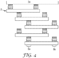
- the roll may also favorably be provided in the form of a cross wound roll.
- Figure 4 shows a schematic, partial cross-section of such a roll.
- the elongated material 2 of the embodiment shown in Figure 4 is the same as that shown in Figures 1 to 3 .
- the elongated material instead of winding the elongated material directly on top of itself, the elongated material is wound helically back and forth across the width of the roll, in particular onto a roll core 1a.
- the positioning of the fastening regions 8a and 8b at or close to the side edges of the elongated material 2 desirably allows for a transverse offset in the next winding of elongated material (and thus crossing winding of the elongated material), since at least one of fastening regions of the next winding can be positioned between those of the previous winding.
- the cross wound roll is wider than the planetary roll, which further facilitates roll stability.
- the provision of a cross wound roll allows for longer roll lengths relative to a planetary roll.
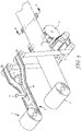
- Figure 5 schematically shows an exemplary embodiment of a method of manufacturing fastening tabs and of fixing said fastening tabs at their manufacturer's end to an absorbent article or to an absorbent article precursor material.
- Figure 5 depicts the manufacture of fastening tabs and the affixing of the generated fastening tabs to an absorbent article precursor material 11, which may be a diaper or incontinence brief precursor web.
- a roll 1 of an elongated material 2 such as the roll shown in Figure 3 , is provided.
- the elongated material 2 is unwound from the roll 1 and an adhesive 19 is applied onto the first major surface 3 of the innermost central region 6a of the central portion 6 by an adhesive applicator head 10.
- the elongated material 2 is then slit along its length through the innermost central region 6a by means of a cutting tool 15 which also slits through the adhesive 19 provided on the first major surface 3 of the innermost central region.
- the elongated material 2 is divided into two endless sheets or strips of tab material, which are essentially mirror images of one another.
- Each of the two elongated strips of tab material comprises one of the two longitudinal edge portions 5a and 5b and a section of the central portion 6.
- Each of the two elongated strips are then cut in the cross direction in order to provide fastening tabs 14, each having a user's end and a manufacturer's end.
- each of the two elongated strips of fastening tab material is fixed to a vacuum wheel 12 and cut by a cutting wheel 13 into individual fastening tabs 14 while being kept in place on the vacuum wheel 12.
- the individually cut fastening tabs 14 are kept in place by the vacuum wheel 12 until they are applied to the diaper or incontinence brief precursor web 11.
- the fastening tabs 14 are affixed pair-wise at an appropriate interval to the web 11 using the adhesive 19 applied previously onto the first major surface 3 of the innermost central region of the central portion 6.
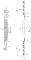
- FIG. 6 shows a schematic cross-section through the diaper or incontinence brief precursor web 11 with the fastening tabs 14 being affixed to the web via the adhesive 19 in the manufacturer's ends 14b with the user's ends 14a extending outwardly away from the web.
- the adhesive 19 is provided to the very edge of the tab in the manufacturer's end 14b, the edge of the tab is cleanly adhered to the web with no remaining flap of non-adherent tab material.
- fastening tabs may be attached to absorbent articles per se or to alternative absorbent article precursor materials.
- fastening tabs 14 may be instead, affixed to an ear web, said ear web may, in turn, be affixed to a diaper or incontinence brief precursor web.
- the fastening tabs may also be affixed to the absorbent articles or absorbent article precursor materials by other techniques such as ultrasound welding, hot-air welding or the like. In such cases, one would dispense with the step of applying adhesive onto the first major surface of the elongated material e.g. as shown in Figure 5 .
Landscapes
- Health & Medical Sciences (AREA)
- Engineering & Computer Science (AREA)
- Animal Behavior & Ethology (AREA)
- General Health & Medical Sciences (AREA)
- Biomedical Technology (AREA)
- Heart & Thoracic Surgery (AREA)
- Vascular Medicine (AREA)
- Life Sciences & Earth Sciences (AREA)
- Veterinary Medicine (AREA)
- Epidemiology (AREA)
- Public Health (AREA)
- Mechanical Engineering (AREA)
- Manufacturing & Machinery (AREA)
- Absorbent Articles And Supports Therefor (AREA)
- Slide Fasteners, Snap Fasteners, And Hook Fasteners (AREA)
- Wire Bonding (AREA)
Claims (17)
- Eine Rolle (1) eines länglichen Materials (2) zur Herstellung von Befestigungslaschen, wobei das längliche Material (2) eine erste (3) und ein zweite (4) Hauptoberfläche, zwei Längskantenabschnitte (5a, 5b) und einen Mittelteil (6), der in Breitenrichtung zwischen den zwei Längskantenabschnitten (5a, 5b) bereitgestellt ist, umfasst,- wobei die Breite jedes Längskantenabschnitts (5a, 5b) höchstens 30 % der Gesamtbreite des länglichen Materials (2) beträgt, wobei- jeder der zwei Längskantenabschnitte (5a, 5b) mechanische Befestigungselemente (8) aufweist, die auf mindestens einem Bereich der ersten Hauptoberfläche (3) bereitgestellt sind, wobei- der Mittelteil (6) einen innersten Mittelbereich (6a) umfasst, wobei die erste Hauptoberfläche (3) des innersten Mittelbereichs frei von Befestigungselementen ist, und wobei- die zweite Hauptoberfläche (4) frei von Klebstoff ist.
- Die Rolle nach Anspruch 1, wobei die erste Hauptoberfläche (3) des innersten Mittelbereichs des Mittelteils (6) keinen Klebstoff aufweist.
- Die Rolle nach Anspruch 1 oder 2, wobei die Breite des innersten Mittelbereichs bis zu 30 % der Gesamtbreite des länglichen Materials, insbesondere im Bereich von etwa 7 % bis (einschließlich) etwa 30 % der Gesamtbreite des länglichen Materials, beträgt; und/oder wobei die Breite jedes Längskantenabschnitts (5a, 5b) mindestens 13 % der Gesamtbreite des länglichen Materials (2) beträgt.
- Die Rolle nach einem der vorstehenden Ansprüche, wobei jeder der Längskantenabschnitte (5a, 5b) einen äußersten Kantenbereich (7a, 7b) umfasst, dessen erste Hauptoberfläche (3) keine Befestigungselemente aufweist.
- Die Rolle nach Anspruch 4, wobei die Breite eines jeden der äußersten Kantenbereiche (7a, 7b) einen Bereich zwischen 3 % und (einschließlich) 10 % der Gesamtbreite des länglichen Materials (2) beträgt und/oder wobei die Breite jeder der äußersten Kantenbereiche (7a, 7b) einen Bereich von 3 mm bis (einschließlich) 12 mm, vorzugsweise jedoch von 5 mm bis (einschließlich) 9 mm beträgt.
- Die Rolle nach einem der vorherigen Ansprüche, wobei jeder der Längskantenabschnitte (5a, 5b) einen Befestigungsbereich (8a, 8b) umfasst, wobei die Befestigungselemente (8) sich auf der ersten Hauptoberfläche (3) eines jeden der Befestigungsbereiche (8a, 8b) befinden.
- Die Rolle nach Anspruch 6, wobei die Breite eines jeden der Befestigungsbereiche (8a, 8b) sich in einem Bereich zwischen 3 % und (einschließlich) 30 % (im Besonderen zwischen 10 % und (einschließlich) 27 % der Gesamtbreite des länglichen Materials (2), und/oder wobei die Breite eines jeden der Befestigungsbereiche (8a, 8b) sich in einem Bereich zwischen 10 mm und (einschließlich) 30 mm, vorzugsweise zwischen 13 mm und (einschließlich) 25 mm befindet.
- Die Rolle nach einem der vorstehenden Ansprüche, wobei das längliche Material (2) als Schichtstoff vorhanden ist, der ein Trägerband (2a) umfasst, welches sich über die Gesamtbreite des länglichen Materials und eines Befestigungsmaterials (28), welches eine Vielzahl von Befestigungselementen (8) enthält, erstreckt, wobei jeder Längskantenabschnitt (5a, 5b) mit mindestens einem länglichen Streifen des Befestigungsmaterials bereitgestellt ist.
- Die Rolle nach Anspruch 8, wobei der mindestens eine längliche Streifen des Befestigungsmaterials (28) in jedem Längskantenabschnitt direkt oder indirekt an der Trägerbahn befestigt ist, insbesondere durch Klebstoff (9), Ultraschallschweißen und/oder Heißluftschweißen oder durch In-situ-Lamination; und/oder wobei die Trägerbahn ein Material umfasst, das aus der Gruppe ausgewählt ist, die aus Folien, Vliesstoffen, Textilien, Schäumen und Kombinationen davon besteht.
- Die Rolle nach einem der vorstehenden Ansprüche, wobei die Befestigungselemente (8) Befestigungselemente mit Außenstecker, insbesondere ausgewählt aus der Gruppe bestehend aus Häkchenverschlüssen, pilzförmigen, stielförmigen, becherförmigen, T-förmigen Befestigungselementen und Mischungen davon umfassen.
- Die Rolle nach einem der vorstehenden Ansprüche, wobei die Rolle eine Planetenrolle oder eine Kreuzwickelrolle ist.
- Ein Verfahren zum Herstellen von Befestigungslaschen (14), wobei das Verfahren die folgenden Schritte umfasst:a) Bereitstellen einer Rolle (1) eines länglichen Materials (2) zum Herstellen von Befestigungslaschen (2) nach einem der vorstehenden Ansprüche;b) Abrollen des länglichen Materials von der Rolle (1);c) Schlitzen des länglichen Materials (2) entlang seiner Länge durch den innersten Mittelbereich (6a) des Mittelteils (6), um zwei längliche Streifen bereitzustellen, die jeweils einen der beiden Längskantenabschnitte und einen Teilabschnitt des Mittelteils umfassen; undd) Schneiden jedes der beiden länglichen Streifen, um Befestigungslaschen (14) mit einem Benutzer-Ende (14a) und einem Hersteller-Ende (14b) bereitzustellen.
- Das Verfahren nach Anspruch 12, das ferner den Schritt umfasst, dass mindestens eine der Befestigungslaschen (14) am Hersteller-Ende (14b) an einem Absorptionsartikel oder ein Absorptionsartikel-Vorläufermaterial (11) angebracht wird, insbesondere durch eines von oder eine Kombination aus: Ultraschallverschweißung, Heißluftverschweißung und Klebehaftung, wobei der Schritt der Anhaftung im Wesentlichen gleichzeitig mit oder nach dem Schritt d) des Schneidens erfolgt.
- Das Verfahren nach Anspruch 12, das ferner den Schritt umfasst, dass zwischen den Schritten b) und c) ein Klebstoff (19) auf die erste Hauptoberfläche (3) mindestens eines Teils des innersten Mittelbereichs (6a) des Mittelteils (6) angebracht wird.
- Das Verfahren nach Anspruch 14, wobei Schritt c) das Schlitzen durch den Klebstoff (19) umfasst, der auf der ersten Hauptoberfläche (3) des innersten Mittelbereichs bereitgestellt ist.
- Verfahren nach Anspruch 14 oder 15, das ferner den Schritt der Anhaftung mindestens einer der Befestigungslaschen (14) an ihrem Hersteller-Ende (14b) an einen Absorptionsartikel oder ein Absorptionsartikel-Vorläufermaterial (11, 111) umfasst, unter Anwendung des Klebstoffs (19), wobei der Schritt der Anhaftung im Wesentlichen gleichzeitig mit oder nach dem Schritt d) des Schneidens erfolgt.
- Das Verfahren nach Anspruch 13 oder 16, wobei der Absorptionsartikel eine Windel oder eine Inkontinenzhose ist; und/oder wobei das Absorptionsartikel-Vorläufermaterial eine Windelvorläuferbahn, eine Inkontinenzhose-Vorläuferbahn oder eine Ohrbahn ist.
Applications Claiming Priority (2)
| Application Number | Priority Date | Filing Date | Title |
|---|---|---|---|
| EP14168822.6A EP2946756A1 (de) | 2014-05-19 | 2014-05-19 | Rollen zur Herstellung von Befestigungsschellen |
| PCT/US2015/031526 WO2015179368A1 (en) | 2014-05-19 | 2015-05-19 | Rolls for manufacture of fastening tabs |
Publications (3)
| Publication Number | Publication Date |
|---|---|
| EP3145466A1 EP3145466A1 (de) | 2017-03-29 |
| EP3145466B1 EP3145466B1 (de) | 2018-06-20 |
| EP3145466B2 true EP3145466B2 (de) | 2023-01-11 |
Family
ID=50731992
Family Applications (2)
| Application Number | Title | Priority Date | Filing Date |
|---|---|---|---|
| EP14168822.6A Withdrawn EP2946756A1 (de) | 2014-05-09 | 2014-05-19 | Rollen zur Herstellung von Befestigungsschellen |
| EP15727768.2A Active EP3145466B2 (de) | 2014-05-19 | 2015-05-19 | Rollen zur herstellung von befestigungsschellen |
Family Applications Before (1)
| Application Number | Title | Priority Date | Filing Date |
|---|---|---|---|
| EP14168822.6A Withdrawn EP2946756A1 (de) | 2014-05-09 | 2014-05-19 | Rollen zur Herstellung von Befestigungsschellen |
Country Status (8)
| Country | Link |
|---|---|
| US (2) | US20170079384A1 (de) |
| EP (2) | EP2946756A1 (de) |
| JP (1) | JP2017515608A (de) |
| CN (1) | CN106456420B (de) |
| BR (1) | BR112016027219B1 (de) |
| CL (1) | CL2016002943A1 (de) |
| ES (1) | ES2686291T5 (de) |
| WO (1) | WO2015179368A1 (de) |
Families Citing this family (2)
| Publication number | Priority date | Publication date | Assignee | Title |
|---|---|---|---|---|
| CN108471845B (zh) * | 2015-12-21 | 2021-06-18 | 3M创新有限公司 | 紧固制品及其制备方法 |
| US20230102306A1 (en) * | 2017-06-29 | 2023-03-30 | 3M Innovative Properties Company | Method of making multiple strips of mechanical fastener |
Citations (8)
| Publication number | Priority date | Publication date | Assignee | Title |
|---|---|---|---|---|
| US4592118A (en) † | 1983-11-18 | 1986-06-03 | Barnhart Industries, Inc. | Fasteners for apparel and methods of manufacturing them |
| FR2767653A1 (fr) † | 1997-09-02 | 1999-03-05 | Tape Ind | Rouleau forme d'une bande continue constituant un element d'attache mecanique du type auto-agrippant a boucle |
| WO2007072386A1 (en) † | 2005-12-22 | 2007-06-28 | The Procter & Gamble Company | Relative stiffness fasteners |
| US20070173781A1 (en) † | 2006-01-25 | 2007-07-26 | Jackson Byron M | Closure tape tab for absorbent article, prelaminated closure tape, and method of manufacturing a closure tape |
| EP2110110A2 (de) † | 2008-04-15 | 2009-10-21 | Koester GmbH & Co. KG | Windelverschlussband, Windel, Halbzeugstreifen, Applikationsverfahren für ein Windelverschlussband und Herstellverfahren für einen Halbzeugstreifen |
| WO2011094474A1 (en) † | 2010-01-29 | 2011-08-04 | Velcro Industries B.V. | Temporary surface protection |
| US20120042483A1 (en) † | 2010-08-18 | 2012-02-23 | Taiwan Paiho Limited | Method for forming hook elements directly on a fabric substrate, apparatus for performing the method, and article manufactured by the method |
| EP2679112A1 (de) † | 2012-06-26 | 2014-01-01 | 3M Innovative Properties Company | Verfahren zur Herstellung von Befestigungsmitteln und Vorläufergewebe, Befestigungsmittel und Vorläufergewebe |
Family Cites Families (8)
| Publication number | Priority date | Publication date | Assignee | Title |
|---|---|---|---|---|
| US3256882A (en) * | 1964-04-28 | 1966-06-21 | Huber Karl | Strapping support |
| US4209016A (en) * | 1977-09-23 | 1980-06-24 | Colgate-Palmolive Company | Diaper with elastic fastener |
| US5231738A (en) * | 1991-12-12 | 1993-08-03 | Kuraray Co., Ltd. | Mixed hook/loop separable fastener and process for its production |
| US5487809A (en) * | 1994-06-21 | 1996-01-30 | The Procter & Gamble Company | Method for manufacturing tape tab stock that may be used to produce tape tab fasteners for disposable absorbent articles |
| US7014906B2 (en) * | 2003-10-14 | 2006-03-21 | 3M Innovative Properties Company | Hook fastener and method of making |
| US8777919B2 (en) * | 2010-12-07 | 2014-07-15 | 3M Innovative Properties Company | Fastening tab and method of making the same |
| TWI616195B (zh) | 2011-02-16 | 2018-03-01 | 3M新設資產公司 | 製造一機械式緊固件之方法、網狀機械式緊固件、及網狀機械式緊固層壓物 |
| USD671225S1 (en) * | 2012-04-03 | 2012-11-20 | Higley Tyler M | Wrist warmer |
-
2014
- 2014-05-19 EP EP14168822.6A patent/EP2946756A1/de not_active Withdrawn
-
2015
- 2015-05-19 EP EP15727768.2A patent/EP3145466B2/de active Active
- 2015-05-19 WO PCT/US2015/031526 patent/WO2015179368A1/en not_active Ceased
- 2015-05-19 CN CN201580027527.6A patent/CN106456420B/zh not_active Expired - Fee Related
- 2015-05-19 ES ES15727768T patent/ES2686291T5/es active Active
- 2015-05-19 US US15/312,145 patent/US20170079384A1/en not_active Abandoned
- 2015-05-19 BR BR112016027219-6A patent/BR112016027219B1/pt active IP Right Grant
- 2015-05-19 JP JP2016568575A patent/JP2017515608A/ja not_active Withdrawn
-
2016
- 2016-11-18 CL CL2016002943A patent/CL2016002943A1/es unknown
-
2022
- 2022-08-29 US US17/822,862 patent/US20220400819A1/en not_active Abandoned
Patent Citations (8)
| Publication number | Priority date | Publication date | Assignee | Title |
|---|---|---|---|---|
| US4592118A (en) † | 1983-11-18 | 1986-06-03 | Barnhart Industries, Inc. | Fasteners for apparel and methods of manufacturing them |
| FR2767653A1 (fr) † | 1997-09-02 | 1999-03-05 | Tape Ind | Rouleau forme d'une bande continue constituant un element d'attache mecanique du type auto-agrippant a boucle |
| WO2007072386A1 (en) † | 2005-12-22 | 2007-06-28 | The Procter & Gamble Company | Relative stiffness fasteners |
| US20070173781A1 (en) † | 2006-01-25 | 2007-07-26 | Jackson Byron M | Closure tape tab for absorbent article, prelaminated closure tape, and method of manufacturing a closure tape |
| EP2110110A2 (de) † | 2008-04-15 | 2009-10-21 | Koester GmbH & Co. KG | Windelverschlussband, Windel, Halbzeugstreifen, Applikationsverfahren für ein Windelverschlussband und Herstellverfahren für einen Halbzeugstreifen |
| WO2011094474A1 (en) † | 2010-01-29 | 2011-08-04 | Velcro Industries B.V. | Temporary surface protection |
| US20120042483A1 (en) † | 2010-08-18 | 2012-02-23 | Taiwan Paiho Limited | Method for forming hook elements directly on a fabric substrate, apparatus for performing the method, and article manufactured by the method |
| EP2679112A1 (de) † | 2012-06-26 | 2014-01-01 | 3M Innovative Properties Company | Verfahren zur Herstellung von Befestigungsmitteln und Vorläufergewebe, Befestigungsmittel und Vorläufergewebe |
Also Published As
| Publication number | Publication date |
|---|---|
| EP2946756A1 (de) | 2015-11-25 |
| EP3145466B1 (de) | 2018-06-20 |
| EP3145466A1 (de) | 2017-03-29 |
| US20220400819A1 (en) | 2022-12-22 |
| CN106456420B (zh) | 2020-03-06 |
| JP2017515608A (ja) | 2017-06-15 |
| BR112016027219B1 (pt) | 2022-04-26 |
| ES2686291T5 (es) | 2023-03-27 |
| CN106456420A (zh) | 2017-02-22 |
| CL2016002943A1 (es) | 2017-05-19 |
| US20170079384A1 (en) | 2017-03-23 |
| WO2015179368A1 (en) | 2015-11-26 |
| BR112016027219A2 (de) | 2017-08-15 |
| ES2686291T3 (es) | 2018-10-17 |
Similar Documents
| Publication | Publication Date | Title |
|---|---|---|
| US11690767B2 (en) | Apparatus and methods for securing elastic to a carrier web | |
| TWI571250B (zh) | 繫固帶及其製造方法 | |
| EP3024904B1 (de) | Umhüllende bahnmaterialanordnung und umhüllungsverfahren | |
| JP6359723B2 (ja) | 冠面を使用して機械的ファスナを製造する方法 | |
| US7470340B2 (en) | Method for the production of a laminate closure material | |
| US9713558B2 (en) | Absorbent article including laminate and method of making the same | |
| US20220400819A1 (en) | Rolls for Manufacture of Fastening Tabs | |
| KR20140010967A (ko) | 다층 마스킹 테이프 | |
| CN105682631B (zh) | 紧固层合物及其制备方法 | |
| EP3307532A1 (de) | Verbundfolie mit einer rückschicht und folienrolle davon | |
| CN203915237U (zh) | 一种用于封闭系统的连续条状物卷及由其形成的封闭系统 | |
| KR100989873B1 (ko) | 롤 타입 접착테이프 및 그의 제조방법 | |
| JP7709261B2 (ja) | フックシート、およびシートロール | |
| JP2006198016A (ja) | 絆創膏のシート体及び積層体 |
Legal Events
| Date | Code | Title | Description |
|---|---|---|---|
| STAA | Information on the status of an ep patent application or granted ep patent |
Free format text: STATUS: THE INTERNATIONAL PUBLICATION HAS BEEN MADE |
|
| PUAI | Public reference made under article 153(3) epc to a published international application that has entered the european phase |
Free format text: ORIGINAL CODE: 0009012 |
|
| STAA | Information on the status of an ep patent application or granted ep patent |
Free format text: STATUS: REQUEST FOR EXAMINATION WAS MADE |
|
| 17P | Request for examination filed |
Effective date: 20161214 |
|
| AK | Designated contracting states |
Kind code of ref document: A1 Designated state(s): AL AT BE BG CH CY CZ DE DK EE ES FI FR GB GR HR HU IE IS IT LI LT LU LV MC MK MT NL NO PL PT RO RS SE SI SK SM TR |
|
| AX | Request for extension of the european patent |
Extension state: BA ME |
|
| DAV | Request for validation of the european patent (deleted) | ||
| DAX | Request for extension of the european patent (deleted) | ||
| GRAP | Despatch of communication of intention to grant a patent |
Free format text: ORIGINAL CODE: EPIDOSNIGR1 |
|
| STAA | Information on the status of an ep patent application or granted ep patent |
Free format text: STATUS: GRANT OF PATENT IS INTENDED |
|
| INTG | Intention to grant announced |
Effective date: 20180110 |
|
| GRAS | Grant fee paid |
Free format text: ORIGINAL CODE: EPIDOSNIGR3 |
|
| GRAA | (expected) grant |
Free format text: ORIGINAL CODE: 0009210 |
|
| STAA | Information on the status of an ep patent application or granted ep patent |
Free format text: STATUS: THE PATENT HAS BEEN GRANTED |
|
| AK | Designated contracting states |
Kind code of ref document: B1 Designated state(s): AL AT BE BG CH CY CZ DE DK EE ES FI FR GB GR HR HU IE IS IT LI LT LU LV MC MK MT NL NO PL PT RO RS SE SI SK SM TR |
|
| REG | Reference to a national code |
Ref country code: GB Ref legal event code: FG4D |
|
| REG | Reference to a national code |
Ref country code: IE Ref legal event code: FG4D |
|
| REG | Reference to a national code |
Ref country code: AT Ref legal event code: REF Ref document number: 1010050 Country of ref document: AT Kind code of ref document: T Effective date: 20180715 |
|
| REG | Reference to a national code |
Ref country code: DE Ref legal event code: R096 Ref document number: 602015012549 Country of ref document: DE |
|
| REG | Reference to a national code |
Ref country code: ES Ref legal event code: FG2A Ref document number: 2686291 Country of ref document: ES Kind code of ref document: T3 Effective date: 20181017 |
|
| REG | Reference to a national code |
Ref country code: NL Ref legal event code: MP Effective date: 20180620 |
|
| PG25 | Lapsed in a contracting state [announced via postgrant information from national office to epo] |
Ref country code: LT Free format text: LAPSE BECAUSE OF FAILURE TO SUBMIT A TRANSLATION OF THE DESCRIPTION OR TO PAY THE FEE WITHIN THE PRESCRIBED TIME-LIMIT Effective date: 20180620 Ref country code: FI Free format text: LAPSE BECAUSE OF FAILURE TO SUBMIT A TRANSLATION OF THE DESCRIPTION OR TO PAY THE FEE WITHIN THE PRESCRIBED TIME-LIMIT Effective date: 20180620 Ref country code: NO Free format text: LAPSE BECAUSE OF FAILURE TO SUBMIT A TRANSLATION OF THE DESCRIPTION OR TO PAY THE FEE WITHIN THE PRESCRIBED TIME-LIMIT Effective date: 20180920 Ref country code: BG Free format text: LAPSE BECAUSE OF FAILURE TO SUBMIT A TRANSLATION OF THE DESCRIPTION OR TO PAY THE FEE WITHIN THE PRESCRIBED TIME-LIMIT Effective date: 20180920 Ref country code: SE Free format text: LAPSE BECAUSE OF FAILURE TO SUBMIT A TRANSLATION OF THE DESCRIPTION OR TO PAY THE FEE WITHIN THE PRESCRIBED TIME-LIMIT Effective date: 20180620 |
|
| REG | Reference to a national code |
Ref country code: LT Ref legal event code: MG4D |
|
| PG25 | Lapsed in a contracting state [announced via postgrant information from national office to epo] |
Ref country code: GR Free format text: LAPSE BECAUSE OF FAILURE TO SUBMIT A TRANSLATION OF THE DESCRIPTION OR TO PAY THE FEE WITHIN THE PRESCRIBED TIME-LIMIT Effective date: 20180921 Ref country code: HR Free format text: LAPSE BECAUSE OF FAILURE TO SUBMIT A TRANSLATION OF THE DESCRIPTION OR TO PAY THE FEE WITHIN THE PRESCRIBED TIME-LIMIT Effective date: 20180620 Ref country code: RS Free format text: LAPSE BECAUSE OF FAILURE TO SUBMIT A TRANSLATION OF THE DESCRIPTION OR TO PAY THE FEE WITHIN THE PRESCRIBED TIME-LIMIT Effective date: 20180620 Ref country code: LV Free format text: LAPSE BECAUSE OF FAILURE TO SUBMIT A TRANSLATION OF THE DESCRIPTION OR TO PAY THE FEE WITHIN THE PRESCRIBED TIME-LIMIT Effective date: 20180620 |
|
| REG | Reference to a national code |
Ref country code: AT Ref legal event code: MK05 Ref document number: 1010050 Country of ref document: AT Kind code of ref document: T Effective date: 20180620 |
|
| PG25 | Lapsed in a contracting state [announced via postgrant information from national office to epo] |
Ref country code: NL Free format text: LAPSE BECAUSE OF FAILURE TO SUBMIT A TRANSLATION OF THE DESCRIPTION OR TO PAY THE FEE WITHIN THE PRESCRIBED TIME-LIMIT Effective date: 20180620 |
|
| PG25 | Lapsed in a contracting state [announced via postgrant information from national office to epo] |
Ref country code: RO Free format text: LAPSE BECAUSE OF FAILURE TO SUBMIT A TRANSLATION OF THE DESCRIPTION OR TO PAY THE FEE WITHIN THE PRESCRIBED TIME-LIMIT Effective date: 20180620 Ref country code: CZ Free format text: LAPSE BECAUSE OF FAILURE TO SUBMIT A TRANSLATION OF THE DESCRIPTION OR TO PAY THE FEE WITHIN THE PRESCRIBED TIME-LIMIT Effective date: 20180620 Ref country code: SK Free format text: LAPSE BECAUSE OF FAILURE TO SUBMIT A TRANSLATION OF THE DESCRIPTION OR TO PAY THE FEE WITHIN THE PRESCRIBED TIME-LIMIT Effective date: 20180620 Ref country code: PL Free format text: LAPSE BECAUSE OF FAILURE TO SUBMIT A TRANSLATION OF THE DESCRIPTION OR TO PAY THE FEE WITHIN THE PRESCRIBED TIME-LIMIT Effective date: 20180620 Ref country code: AT Free format text: LAPSE BECAUSE OF FAILURE TO SUBMIT A TRANSLATION OF THE DESCRIPTION OR TO PAY THE FEE WITHIN THE PRESCRIBED TIME-LIMIT Effective date: 20180620 Ref country code: EE Free format text: LAPSE BECAUSE OF FAILURE TO SUBMIT A TRANSLATION OF THE DESCRIPTION OR TO PAY THE FEE WITHIN THE PRESCRIBED TIME-LIMIT Effective date: 20180620 Ref country code: IS Free format text: LAPSE BECAUSE OF FAILURE TO SUBMIT A TRANSLATION OF THE DESCRIPTION OR TO PAY THE FEE WITHIN THE PRESCRIBED TIME-LIMIT Effective date: 20181020 |
|
| PG25 | Lapsed in a contracting state [announced via postgrant information from national office to epo] |
Ref country code: IT Free format text: LAPSE BECAUSE OF FAILURE TO SUBMIT A TRANSLATION OF THE DESCRIPTION OR TO PAY THE FEE WITHIN THE PRESCRIBED TIME-LIMIT Effective date: 20180620 Ref country code: SM Free format text: LAPSE BECAUSE OF FAILURE TO SUBMIT A TRANSLATION OF THE DESCRIPTION OR TO PAY THE FEE WITHIN THE PRESCRIBED TIME-LIMIT Effective date: 20180620 |
|
| REG | Reference to a national code |
Ref country code: DE Ref legal event code: R026 Ref document number: 602015012549 Country of ref document: DE |
|
| PLBI | Opposition filed |
Free format text: ORIGINAL CODE: 0009260 |
|
| PLAX | Notice of opposition and request to file observation + time limit sent |
Free format text: ORIGINAL CODE: EPIDOSNOBS2 |
|
| 26 | Opposition filed |
Opponent name: VELCRO USA INC. Effective date: 20190320 |
|
| PG25 | Lapsed in a contracting state [announced via postgrant information from national office to epo] |
Ref country code: DK Free format text: LAPSE BECAUSE OF FAILURE TO SUBMIT A TRANSLATION OF THE DESCRIPTION OR TO PAY THE FEE WITHIN THE PRESCRIBED TIME-LIMIT Effective date: 20180620 |
|
| PGFP | Annual fee paid to national office [announced via postgrant information from national office to epo] |
Ref country code: BE Payment date: 20190315 Year of fee payment: 5 |
|
| PLBB | Reply of patent proprietor to notice(s) of opposition received |
Free format text: ORIGINAL CODE: EPIDOSNOBS3 |
|
| PG25 | Lapsed in a contracting state [announced via postgrant information from national office to epo] |
Ref country code: SI Free format text: LAPSE BECAUSE OF FAILURE TO SUBMIT A TRANSLATION OF THE DESCRIPTION OR TO PAY THE FEE WITHIN THE PRESCRIBED TIME-LIMIT Effective date: 20180620 |
|
| PG25 | Lapsed in a contracting state [announced via postgrant information from national office to epo] |
Ref country code: AL Free format text: LAPSE BECAUSE OF FAILURE TO SUBMIT A TRANSLATION OF THE DESCRIPTION OR TO PAY THE FEE WITHIN THE PRESCRIBED TIME-LIMIT Effective date: 20180620 |
|
| REG | Reference to a national code |
Ref country code: CH Ref legal event code: PL |
|
| GBPC | Gb: european patent ceased through non-payment of renewal fee |
Effective date: 20190519 |
|
| PG25 | Lapsed in a contracting state [announced via postgrant information from national office to epo] |
Ref country code: MC Free format text: LAPSE BECAUSE OF FAILURE TO SUBMIT A TRANSLATION OF THE DESCRIPTION OR TO PAY THE FEE WITHIN THE PRESCRIBED TIME-LIMIT Effective date: 20180620 Ref country code: LI Free format text: LAPSE BECAUSE OF NON-PAYMENT OF DUE FEES Effective date: 20190531 Ref country code: CH Free format text: LAPSE BECAUSE OF NON-PAYMENT OF DUE FEES Effective date: 20190531 |
|
| PG25 | Lapsed in a contracting state [announced via postgrant information from national office to epo] |
Ref country code: LU Free format text: LAPSE BECAUSE OF NON-PAYMENT OF DUE FEES Effective date: 20190519 |
|
| PG25 | Lapsed in a contracting state [announced via postgrant information from national office to epo] |
Ref country code: TR Free format text: LAPSE BECAUSE OF FAILURE TO SUBMIT A TRANSLATION OF THE DESCRIPTION OR TO PAY THE FEE WITHIN THE PRESCRIBED TIME-LIMIT Effective date: 20180620 |
|
| PG25 | Lapsed in a contracting state [announced via postgrant information from national office to epo] |
Ref country code: GB Free format text: LAPSE BECAUSE OF NON-PAYMENT OF DUE FEES Effective date: 20190519 Ref country code: IE Free format text: LAPSE BECAUSE OF NON-PAYMENT OF DUE FEES Effective date: 20190519 |
|
| PLAY | Examination report in opposition despatched + time limit |
Free format text: ORIGINAL CODE: EPIDOSNORE2 |
|
| PG25 | Lapsed in a contracting state [announced via postgrant information from national office to epo] |
Ref country code: PT Free format text: LAPSE BECAUSE OF FAILURE TO SUBMIT A TRANSLATION OF THE DESCRIPTION OR TO PAY THE FEE WITHIN THE PRESCRIBED TIME-LIMIT Effective date: 20181022 Ref country code: FR Free format text: LAPSE BECAUSE OF NON-PAYMENT OF DUE FEES Effective date: 20190531 |
|
| PLAB | Opposition data, opponent's data or that of the opponent's representative modified |
Free format text: ORIGINAL CODE: 0009299OPPO |
|
| R26 | Opposition filed (corrected) |
Opponent name: VELCRO USA INC. Effective date: 20190320 |
|
| PLBC | Reply to examination report in opposition received |
Free format text: ORIGINAL CODE: EPIDOSNORE3 |
|
| REG | Reference to a national code |
Ref country code: BE Ref legal event code: MM Effective date: 20200531 |
|
| PG25 | Lapsed in a contracting state [announced via postgrant information from national office to epo] |
Ref country code: BE Free format text: LAPSE BECAUSE OF NON-PAYMENT OF DUE FEES Effective date: 20200531 Ref country code: CY Free format text: LAPSE BECAUSE OF FAILURE TO SUBMIT A TRANSLATION OF THE DESCRIPTION OR TO PAY THE FEE WITHIN THE PRESCRIBED TIME-LIMIT Effective date: 20180620 |
|
| PG25 | Lapsed in a contracting state [announced via postgrant information from national office to epo] |
Ref country code: MT Free format text: LAPSE BECAUSE OF FAILURE TO SUBMIT A TRANSLATION OF THE DESCRIPTION OR TO PAY THE FEE WITHIN THE PRESCRIBED TIME-LIMIT Effective date: 20180620 Ref country code: HU Free format text: LAPSE BECAUSE OF FAILURE TO SUBMIT A TRANSLATION OF THE DESCRIPTION OR TO PAY THE FEE WITHIN THE PRESCRIBED TIME-LIMIT; INVALID AB INITIO Effective date: 20150519 |
|
| PG25 | Lapsed in a contracting state [announced via postgrant information from national office to epo] |
Ref country code: MK Free format text: LAPSE BECAUSE OF FAILURE TO SUBMIT A TRANSLATION OF THE DESCRIPTION OR TO PAY THE FEE WITHIN THE PRESCRIBED TIME-LIMIT Effective date: 20180620 |
|
| PUAH | Patent maintained in amended form |
Free format text: ORIGINAL CODE: 0009272 |
|
| STAA | Information on the status of an ep patent application or granted ep patent |
Free format text: STATUS: PATENT MAINTAINED AS AMENDED |
|
| 27A | Patent maintained in amended form |
Effective date: 20230111 |
|
| AK | Designated contracting states |
Kind code of ref document: B2 Designated state(s): AL AT BE BG CH CY CZ DE DK EE ES FI FR GB GR HR HU IE IS IT LI LT LU LV MC MK MT NL NO PL PT RO RS SE SI SK SM TR |
|
| REG | Reference to a national code |
Ref country code: DE Ref legal event code: R102 Ref document number: 602015012549 Country of ref document: DE |
|
| REG | Reference to a national code |
Ref country code: ES Ref legal event code: DC2A Ref document number: 2686291 Country of ref document: ES Kind code of ref document: T5 Effective date: 20230327 |
|
| PGFP | Annual fee paid to national office [announced via postgrant information from national office to epo] |
Ref country code: DE Payment date: 20250423 Year of fee payment: 11 |
|
| PGFP | Annual fee paid to national office [announced via postgrant information from national office to epo] |
Ref country code: ES Payment date: 20250602 Year of fee payment: 11 |