EP3145378B1 - Tragstab - Google Patents
Tragstab Download PDFInfo
- Publication number
- EP3145378B1 EP3145378B1 EP15730378.5A EP15730378A EP3145378B1 EP 3145378 B1 EP3145378 B1 EP 3145378B1 EP 15730378 A EP15730378 A EP 15730378A EP 3145378 B1 EP3145378 B1 EP 3145378B1
- Authority
- EP
- European Patent Office
- Prior art keywords
- support bar
- roll
- set forth
- material web
- support rod
- Prior art date
- Legal status (The legal status is an assumption and is not a legal conclusion. Google has not performed a legal analysis and makes no representation as to the accuracy of the status listed.)
- Active
Links
Images


Classifications
-
- A—HUMAN NECESSITIES
- A47—FURNITURE; DOMESTIC ARTICLES OR APPLIANCES; COFFEE MILLS; SPICE MILLS; SUCTION CLEANERS IN GENERAL
- A47K—SANITARY EQUIPMENT NOT OTHERWISE PROVIDED FOR; TOILET ACCESSORIES
- A47K10/00—Body-drying implements; Toilet paper; Holders therefor
- A47K10/24—Towel dispensers, e.g. for piled-up or folded textile towels; Toilet-paper dispensers; Dispensers for piled-up or folded textile towels provided or not with devices for taking-up soiled towels as far as not mechanically driven
- A47K10/32—Dispensers for paper towels or toilet-paper
- A47K10/34—Dispensers for paper towels or toilet-paper dispensing from a web, e.g. with mechanical dispensing means
- A47K10/38—Dispensers for paper towels or toilet-paper dispensing from a web, e.g. with mechanical dispensing means the web being rolled up with or without tearing edge
- A47K10/40—Dispensers for paper towels or toilet-paper dispensing from a web, e.g. with mechanical dispensing means the web being rolled up with or without tearing edge with extensible or collapsible roll supports or roll spindles
-
- A—HUMAN NECESSITIES
- A47—FURNITURE; DOMESTIC ARTICLES OR APPLIANCES; COFFEE MILLS; SPICE MILLS; SUCTION CLEANERS IN GENERAL
- A47K—SANITARY EQUIPMENT NOT OTHERWISE PROVIDED FOR; TOILET ACCESSORIES
- A47K10/00—Body-drying implements; Toilet paper; Holders therefor
- A47K10/24—Towel dispensers, e.g. for piled-up or folded textile towels; Toilet-paper dispensers; Dispensers for piled-up or folded textile towels provided or not with devices for taking-up soiled towels as far as not mechanically driven
- A47K10/32—Dispensers for paper towels or toilet-paper
- A47K2010/3206—Coreless paper rolls
Definitions
- the invention relates to a support rod with two bearing pins for a wound to a coreless roll of material web and a roll, in particular a paper roll with such a support rod.
- such a support bar is provided for roles to be used in a dispenser, which deliver, for example, household paper, sanitary paper, toilet paper, garbage bags, etc.
- a dispenser which deliver, for example, household paper, sanitary paper, toilet paper, garbage bags, etc.
- coreless rolls with the same outside diameter have a larger number of material sections, so that it is quite interesting to use coreless rolls.
- the problem is the attachment of a support rod.
- a proposal for such a support rod is from the US 5,495,997 known.
- the support rod projects beyond the roller on both sides, wherein the protruding parts represent the bearing journals, by means of which the roller is held and guided in the dispenser.
- On one side of the bearing pin has a minimum diameter, and the second bearing journal is provided with a circumferential groove which fits into an undercut guide of the dispenser side wall, so that a twisted arrangement is excluded, and the same unwinding direction of all rollers used is ensured.
- the material web supporting the center part of the support rod is of constant diameter to unroll the roll without difficulty, and provided with four over the length continuous ribs of the same height, so that the cross-section is approximately X-shaped.
- each rib is chamfered.
- the ribs are firmly fixed in the innermost turns of the material web and additionally provide an axial hold so that the roll does not slip off the support rod even in an inclined position.
- this can bring difficulties in the insertion of the support bar with it, since the ribs that extend over the entire length, tear over the entire length of the innermost turns of the material web or impose it, if it can be expected at such material webs quite uniform and accurate winding is lacking.
- the document EP 758 539 shows another support bar.
- the support bar is in several parts and comprises a hollow, over the length of the roller continuous, first part having a stepped tapered insertion end and at the second end a bearing pin which projects beyond a the insertion depth of the flange.
- the support rod further comprises a shorter second part insertable into the cavity of the first part with a tapered insertion end and a second bearing journal outside a flange, and finally a sleeve rotatable on the continuous first part with a spacer ring and a locking ring on which the coreless one Roll is arranged so that they can rotate with the sleeve on the first continuous part.
- the support rod is intended for repeated use, that is, it is disassembled after exhaustion of a role at least in the two each provided with a journal parts, which are then inserted into the next full role.
- a support rod according to the preamble of claim 1 is in the GB1180640 shown.
- the invention has therefore set itself the task of creating the simplest possible multi-part support rod, in which the disadvantages described are eliminated or at least reduced.
- the first and the second part are provided with ribs which are shorter than half the length of the support rod and each rise to the flange.
- the front portion of the first part can therefore be easily inserted into a very small central opening of the coreless roll and through the role push through, whereby the gently rising from the minimum diameter ribs are only at the end in the innermost turns press.
- the second part of the support rod namely the likewise provided with ribbed sleeve is pushed onto the already inserted into the coreless roll first part from the other side.
- the inlet diameter of the sleeve is only slightly larger than the portion of the core member without longitudinal ribs, so that the sleeve can be inserted or pushed without damaging the innermost paper turns.
- the two parts of the support rod lock after mating in particular insoluble, to avoid reuse.
- the first part can have an annular bead which has an obliquely rising surface and a surface sloping perpendicular to the axis. Opposing surfaces or surface portions may be provided on the second part.
- an exemption, recess or weakening be provided so that the latching parts easier to connect and can be separated again only by damage or destruction.
- the flange provided with the second end of the first part has a bore for rotatable and latched receiving a second journal bearing third part.
- the rotatable second bearing journal can provide a mechanical coding by forming a non-rotating surface, when the counterpart is formed in the same way in the introduction section of the dispenser.
- Such a non-rotation surface may be provided on a flat or an end groove of the journal
- the support bar according to the invention may also comprise additional features.
- at least one of the two bearing journals may have an insert, for example a fragrance.
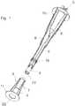
- FIG. 2 are for this purpose schematically locking means 13 indicated that are not accessible from the outside. Outside the roller 3 bearing journals 4, 5 are provided, which are both associated with the first part 6, 7, and guide the roller 3 in guideways 27 of a dispenser 25 from an insertion position 28 in a dispensing position 29.
- the first part 6 of the support rod 1 represents a core part, which in Fig. 1 . 3 and 4 the entire length of the roller 3 comprises and on which the sleeve formed as a second part 7 is attached. Both parts taper towards the front insertion end and have at the other end depending on a flange 10, 11 which abuts against the end face of the roller 3 from the outside or is slightly pressed into it.
- both parts 6, 7 on the circumference with two to six longitudinal ribs 8, 9 are provided, which rise to the flange 10, 11 and each have a maximum length of 40 percent of the support rod 1.
- the facing away from the flange 10 shank of the first part 6 protrudes beyond the roller 3, wherein this area has the smallest diameter, and the first bearing pin 4 forms, which also od with a bore 23 for receiving an insert, such as a perfume capsule. can be provided.
- annular bead 19 and an annular shoulder 18 are provided in this embodiment.
- the annular bead 19 is formed at some axial distance from the bearing pin 4 on the first part 6, and has on the side of the journal 4 an inclined surface and on the other side approximately perpendicular to the axis 2 of the support rod 1 latching surface.
- a bore 22 is provided, the flange 11 closer portion has a larger diameter than the section lying at the insertion end. The transition of the two bore sections forms the annular shoulder 18, behind which the perpendicular to the axis 2 surface of the annular bead 19 is locked when attaching the second part 7 to the first part 6.
- the first part 6 is inserted with the thin bearing pin 4 from one end face into the central opening of the coreless roll 3, and then the second part 7 is inserted with its front, thinner end of the other end side of the roller 3 , wherein in the end position, the second part 7 is latched on the thinner, front end of the first part 6 and both flanges 10 and 11 abut against the end face of the roller 3 and are slightly pressed into this.
- the longitudinal ribs 8, 9 engage from the ends about the same extent in the innermost turns of the roller 3 and cause an approximately balanced hold to exhaustion, which, as from Fig. 3 can be seen, in the central region 21 can be scanned, in which between the innermost winding of the roller 3 and the support rod 1 remains a free space.
- Fig. 3 to 5 show, the end of the first part 6, on which the flange 10 is formed, a bore 14 in which an undercut annular groove 15 is provided, which is open between the longitudinal ribs 8 to the outside.
- the third part 12 protrudes beyond the flange 10 of the first part 6 and forms there the second bearing journal 5, which is provided, for example, with an end-side groove 20 and can be inserted therewith into a counterpart of the guide track 27 on the dispenser 25 in the shaping ,
- the third part 12 is preferably rotatably guided in the dispenser 25, since the support rod 1 can be rotated with the roller 3 on the third part 12.
- other non-rotating surfaces may be formed as guide surfaces, for example, parallel flats or the like.
- Fig. 5 shows a second not erfindungdstructuree execution of a two-part support rod 1, in which the first part 6 passes through the roller 3 over the entire length and the projecting end of the bearing pin 4 forms.
- the second part in the form of the described sleeve is missing.
- In the bore 14 of the first part 6 of the third part 12 is rotatably locked with groove 20.
- the bearing pin 5 with the groove 20 is a non-rotatable, projecting end of the first part 6, then the guide track 27 is formed gegentechnisch only in the insertion 28, while the subsequent section allows the rotation of the support rod 1 with roller 3 to the dispensing position 29 as indicated by the arrow on the end 26 of the material web hanging out of the dispenser 25.
- the guide track 27 in the dispenser 25 between the insertion 28 and the dispensing position 29 may be similar, for example, formed as a web, wherein the removal of the web 26 from the dispenser 25 by the rolling of the roller. 3 nevertheless possible.
Landscapes
- Health & Medical Sciences (AREA)
- Public Health (AREA)
- Replacement Of Web Rolls (AREA)
- Unwinding Webs (AREA)
- Storage Of Web-Like Or Filamentary Materials (AREA)
- Sanitary Thin Papers (AREA)
- Winding Of Webs (AREA)
Description
- Die Erfindung betrifft einen Tragstab mit zwei Lagerzapfen für eine zu einer kernlosen Rolle gewickelte Materialbahn sowie eine Rolle, insbesondere eine Papierrolle mit einem derartigen Tragstab.
- Insbesondere ist ein derartiger Tragstab für in einen Spender einzusetzende Rollen vorgesehen, die beispielsweise Haushaltspapier, Sanitärpapier, Toilettenpapier, Müllsäcke etc. abgeben. Im Gegensatz zu Rollen, bei denen die Materialbahn auf einer Kernhülse aus Karton od. dgl. gewickelt ist, weisen kernlose Rollen bei gleichem Außendurchmesser eine größere Zahl von Materialabschnitten auf, sodass es durchaus von Interesse ist, kernlose Rollen anzuwenden. Problematisch dabei ist aber die Anbringung eines Tragstabes.
- Ein Vorschlag für einen derartigen Tragstab ist aus der
US 5,495,997 bekannt. Der Tragstab überragt die Rolle an beiden Seiten, wobei die vorstehenden Teile die Lagerzapfen darstellen, mittels denen die Rolle im Spender gehalten und geführt ist. An einer Seite weist der Lagerzapfen einen minimalen Durchmesser auf, und der zweite Lagerzapfen ist mit einer Umfangsnut versehen, die in eine hinterschnittene Führung der Spenderseitenwand passt, sodass eine verdrehte Anordnung ausgeschlossen ist, und die gleiche Abrollrichtung aller eingesetzten Rollen sichergestellt wird. Der die Materialbahn stützende Mittelteil des Tragstabs ist von gleich bleibendem Durchmesser, um die Rolle ohne Schwierigkeiten abzurollen, und mit vier über die Länge durchgehenden Rippen gleicher Höhe versehen, sodass der Querschnitt etwa x-förmig ist. Zum Lagerzapfen mit dem kleineren Durchmesser hin ist das Ende jeder Rippe abgeschrägt. Die Rippen legen sich in den innersten Windungen der Materialbahn drehfest fest und bewirken zusätzlich einen axialen Halt, sodass die Rolle auch bei Schräglage nicht vom Tragstab rutscht. Dies kann aber Schwierigkeiten beim Einsetzen des Tragstabs mit sich bringen, da die Rippen, die sich über die gesamte Länge erstrecken, auch über die gesamte Länge die innersten Windungen der Materialbahn aufreißen oder sich darin verhängen können, wenn es an einer bei derartigen Materialbahnen durchaus erwartbaren gleichmäßigen und genauen Wicklung mangelt. Das DokumentEP 758 539 - Ein Tragstab gemäß Oberbegriff des Anspruchs 1 ist in der
GB1180640 - Erfindungsgemäß wird dies durch die Merkmale von Anspruch 1 erreicht. In einer weiteren bevorzugten Ausführung ist vorgesehen, dass der erste und der zweite Teil mit Rippen versehen sind, die kürzer als die halbe Länge des Tragstabs sind und jeweils zum Flansch hin ansteigen. Dadurch ist eine ausgewogene gleichmäßige Stützung der Rolle auf dem Tragstab gegeben, und es verbleibt ein Mittelbereich mit geringstem Durchmesser.
- Der vordere Abschnitt des ersten Teils lässt sich daher problemlos auch in eine sehr kleine Mittelöffnung der kernlosen Rolle einschieben und durch die Rolle durchschieben, wobei die vom minimalen Durchmesser sanft ansteigenden Rippen sich erst zum Schluss in die innersten Windungen eindrücken. Der zweite Teil des Tragstabes, nämlich die ebenfalls mit Rippen versehene Hülse wird auf den in die kernlose Rolle bereits eingesteckten ersten Teil von der anderen Seite aufgeschoben. Der Eintrittsdurchmesser der Hülse ist nur geringfügig größer als der Abschnitt des Kernteiles ohne Längsrippen, sodass auch die Hülse ohne Beschädigung der innersten Papierwindungen ein- bzw. aufgeschoben werden kann.
- Die beiden Teile des Tragstabes verrasten nach dem Zusammenstecken insbesondere unlösbar, um die Wiederverwendung zu vermeiden. Der erste Teil kann hierzu einen Ringwulst aufweisen, der eine schräg ansteigende und eine senkrecht zur Achse abfallende Fläche aufweist. Gegengleiche Flächen oder Flächenabschnitte können am zweiten Teil vorgesehen sein.
- Um das Ineinanderstecken und Verrasten der beiden Teile des Tragstabs zu erleichtern, kann im Umgebungsbereich der Verrastung an zumindest einem der beiden Teile eine Freistellung, Ausnehmung oder Schwächung vorgesehen sein, sodass sich die verrastenden Teile leichter verbinden und nur durch Beschädigung oder Zerstörung wieder trennen lassen.
- In einer bevorzugten Ausführung ist vorgesehen, dass das mit dem Flansch versehene zweite Ende des ersten Teiles eine Bohrung zur drehbaren und verrasteten Aufnahme eines den zweiten Lagerzapfen tragenden dritten Teiles aufweist. Der drehbare zweite Lagerzapfen kann durch eine Ausbildung einer Nichtrotationsfläche eine mechanische Codierung bieten, wenn das Gegenstück im Einführungsabschnitt des Spenders gegengleich ausgebildet wird. Eine derartige Nichtrotationsfläche kann an einer Abflachung oder einer stirnseitigen Nut des Lagerzapfens vorgesehen sein
- In weiterer Folge kann der erfindungsgemäße Tragstab noch zusätzliche Merkmale umfassen. So ist es beispielsweise möglich, dass zumindest einer der beiden Lagerzapfen eine Einlage, beispielsweise einen Duftstoff, aufweist.
- Nachstehend wird nun die Erfindung an Hand der beiliegenden Zeichnung näher beschrieben, ohne darauf beschränkt zu sein.
- Es zeigen:
- Fig. 1
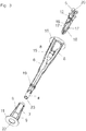
- eine Schrägansicht eines erfindungsgemäßen, zweiteiligen Tragstabs in Explosions-darstellung,
- Fig. 2
- eine schematische Darstellung einer nicht erfindungsgemäßen Ausführung eines zweiteiligen in einer Papierrolle verrasteten Tragstabs,
- Fig. 3
- eine Schrägansicht eines erfindungsgemäßen, dreiteiligen Tragstabs in Explosions-darstellung,
- Fig. 4
- einen Längsschnitt durch den in einer Papierrolle verrasteten Tragstab nach
Fig. 3 , - Fig. 5
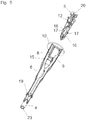
- eine Schrägansicht einer zweiten nicht erfindunsgemäßen Ausführung eines zweiteiligen Tragstabs in Explosionsdarstellung, und
- Fig. 6
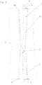
- eine schematische Schrägansicht eines Spenders.
- Ein erste Ausführung eines Tragstabs 1 für eine in
Fig. 2 und4 strichliert angedeutete kernlos gewickelte Rolle 3, insbesondere eine Papierrolle, weist zwei sich verjüngende Teile 6, 7 auf, die von beiden Stirnseiten der Rolle 3 eingesteckt und miteinander insbesondere unlösbar verrastet sind. In der nicht erfindungsgemäßen Ausführung nachFig. 2 sind hiefür schematisch Rastmittel 13 angedeutet, die von außen nicht zugänglich sind. Außerhalb der Rolle 3 sind Lagerzapfen 4, 5 vorgesehen, die beide dem ersten Teil 6, 7 zugeordnet sind, und die Rolle 3 in Führungsbahnen 27 eines Spenders 25 von einer Einführposition 28 in eine Spendeposition 29 leiten. (Fig. 6 ) - Der erste Teil 6 des Tragstabs 1 stellt einen Kernteil dar, der in
Fig. 1 ,3 und4 die gesamte Länge der Rolle 3 umfasst und auf den der als Hülse ausgebildete zweite Teil 7 aufgesteckt ist. Beide Teile verjüngen sich zum vorderen Einsteckende hin und weisen am anderen Ende je einen Flansch 10, 11 auf, der sich an die Stirnseite der Rolle 3 von außen anlegt bzw. geringfügig in sie eingedrückt ist. - In der Ausführung nach
Fig. 1 und3 sind beide Teile 6, 7 am Umfang mit je zwei bis sechs Längsrippen 8, 9 versehen, die zum Flansch 10, 11 hin ansteigen und jeweils eine Länge von maximal 40 Prozent des Tragstabs 1 aufweisen. Das vom Flansch 10 abgewandte Einsteckende des ersten Teils 6 steht über die Rolle 3 vor, wobei dieser Bereich den geringsten Durchmesser aufweist, und den ersten Lagerzapfen 4 bildet, der auch mit einer Bohrung 23 zur Aufnahme einer Einlage, beispielsweise einer Duftstoffkapsel od. dgl. versehen sein kann. - Als Rastmittel 13 sind in dieser Ausführung ein Ringwulst 19 und eine Ringschulter 18 vorgesehen. Der Ringwulst 19 ist mit etwas axialem Abstand vom Lagerzapfen 4 auf dem ersten Teil 6 ausgebildet, und weist an der Seite des Lagerzapfens 4 eine schräg ansteigende Fläche und an der anderen Seite eine etwa senkrecht zur Achse 2 des Tragstabs 1 liegende Rastfläche auf. In dem auf den ersten Teil 6 aufschiebbaren zweiten Teil 7 ist eine Bohrung 22 vorgesehen, deren dem Flansch 11 näherer Abschnitt einen größeren Durchmesser aufweist als der am Einsteckende liegende Abschnitt. Der Übergang der beiden Bohrungsabschnitte bildet die Ringschulter 18, hinter der beim Aufstecken des zweiten Teiles 7 auf den ersten Teil 6 die senkrecht zur Achse 2 liegende Fläche des Ringwulstes 19 verrastet.
- Um nun eine kernlos gewickelte Rolle 3 mit einem Tragstab 1 der in
Fig. 1 gezeigten ersten zweiteiligen Ausführung zu bestücken, wird zuerst der ersten Teil 6 mit dem dünnen Lagerzapfen 4 von einer Stirnseite in die Mittelöffnung der kernlosen Rolle 3 eingeschoben, und dann der zweite Teil 7 mit seinem vorderen, dünneren Ende von der anderen Stirnseite der Rolle 3 eingeschoben, wobei in der Endposition der zweite Teil 7 auf dem dünneren, vorderen Ende des ersten Teils 6 verrastet ist und beide Flansche 10 und 11 an der Stirnseite der Rolle 3 anliegen bzw. leicht in diese eingedrückt sind.
Die Längsrippen 8, 9 greifen von den Enden her etwa gleich weit in die innersten Windungen der Rolle 3 ein und bewirken einen annähernd ausgeglichenen Halt bis zum Aufbrauch, der sich, wie ausFig. 3 ersichtlich, im Mittelbereich 21 abtasten lässt, in dem zwischen der innersten Wicklung der Rolle 3 und dem Tragstab 1 ein Freiraum verbleibt. - Wie
Fig. 3 bis 5 zeigen, weist das Ende des ersten Teils 6, an dem der Flansch 10 ausgebildet ist, eine Bohrung 14 auf, in der eine hinterschnittene Ringnut 15 vorgesehen ist, die zwischen den Längsrippen 8 nach außen offen ist. -
Fig. 3 und4 zeigen einen dreiteiligen Tragstab. Hier ist in die Bohrung 14 des ersten Teiles 6 ein zusätzlicher, dritter Teil 12 eingeschoben, der mit Rastnasen 17 versehen ist, die in der Ringnut 15 verrasten. Der dritte Teil 12 ist im Bereich der Rastnasen 17 gespalten und bildet dort zumindest zwei federnde Zungen 16, die nach innen ausweichen können, wenn der dritte Teil 12 in die Bohrung 14 des ersten Teiles 6 eingeschoben wird. Der dritte Teil 12 steht über den Flansch 10 des ersten Teils 6 vor und bildet dort den zweiten Lagerzapfen 5, der beispielsweise mit einer stirnseitigen Nut 20 versehen ist und mit dieser in ein in der Formgebung entsprechendes Gegenstück der Führungsbahn 27 am Spender 25 eingeschoben werden kann. Der dritte Teil 12 ist im Spender 25 bevorzugt drehfest geführt, da der Tragstab 1 mit der Rolle 3 auf dem dritten Teil 12 verdreht werden kann. Anstelle der stirnseitigen Nut 20 können auch andere Nichtrotationsflächen als Führungsflächen ausgebildet sein, beispielsweise parallele Abflachungen oder dergleichen. -
Fig. 5 zeigt eine zweite nicht erfindungdgemäße Ausführung eines zweiteiligen Tragstabes 1, in der der erste Teil 6 die Rolle 3 über die gesamte Länge durchsetzt und das vorstehende Ende den Lagerzapfen 4 bildet. Der zweite Teil in Form der beschriebenen Hülse fehlt. In der Bohrung 14 des ersten Teiles 6 ist der dritte Teil 12 mit Nut 20 drehbar verrastet. - Wenn gemäß
Fig. 1 der Lagerzapfen 5 mit der Nut 20 ein nicht verdrehbares, vorstehendes Ende des ersten Teiles 6 ist, so ist die Führungsbahn 27 nur in der Einführposition 28 gegengleich ausgebildet, während der anschließende Abschnitt bis in die Spendeposition 29 die Verdrehung des Tragstabs 1 mit Rolle 3 zulässt, wie durch den Pfeil an dem aus dem Spender 25 heraushängenden Ende 26 der Materialbahn angedeutet ist. Wenn der Lagerzapfen 5 mit der Nut 20 hingegen gemäßFig. 3 am zusätzlichen dritten drehbaren Teil 12 vorgesehen ist, so kann die Führungsbahn 27 im Spender 25 zwischen der Einführposition 28 und der Spendeposition 29 gleichartig, beispielsweise als Steg ausgebildet sein, wobei die Entnahme der Materialbahn 26 aus dem Spender 25 durch das Abrollen von der Rolle 3 dennoch möglich ist.
Claims (7)
- Tragstab mit zwei Lagerzapfen (4, 5) für eine zu einer kernlosen Rolle (3) gewickelte Materialbahn (26), der zwei sich verjüngende, von entgegengesetzten Seiten axial in die Rolle (3) einschiebbare Teile (6, 7) umfasst, die unterschiedlich lang sind und jeweils einen Flansch (10, 11) aufweisen, der einen Anschlag für die Einschubtiefe bildet, wobei der erste Teil (6) einen Kernteil bildet und im Gebrauchszustand beidseitig aus der Rolle (3) vorsteht, wobei die vorstehenden Enden beide Lagerzapfen (4, 5) bilden, und wobei der zweite Teil (7) durch eine Hülse gebildet ist, und das Einsteckende des ersten Teiles (6) als erster Lagerzapfen (4) aus dem Flansch (11) der Hülse vorsteht, dadurch gekennzeichnet, dass der zweite Teil (7) auf den ersten Teil (6) aufgeschoben und verrastet ist.
- Tragstab nach Anspruch 1, dadurch gekennzeichnet, dass der erste und der zweite Teil (6, 7) mit Rippen (8, 9) versehen sind, die zum Ende des Tragstabes (1) hin ansteigen, und dass die ansteigenden Abschnitte der Rippen (8, 9) kürzer als die halbe Länge des Tragstabs (1).
- Tragstab nach Anspruch 1 oder 2, dadurch gekennzeichnet, dass das mit dem Flansch (10) versehene zweite Ende des ersten Teiles (6) eine Bohrung (14) aufweist, und ein dritter Teil (12), der einen der beiden Lagerzapfen (5) aufweist, in die Bohrung (14) einschiebbar ist, wobei der in die Bohrung (14) einschiebbare dritte Teil (12) drehbar verrastet ist.
- Tragstab nach einem der Ansprüche 1 bis 3, dadurch gekennzeichnet, dass in der Stirnseite des drehbaren Lagerzapfens (5) eine Nut (20) ausgebildet ist.
- Zu einer kernlosen Rolle (3) gewickelte Materialbahn mit einem Tragstab (1) nach einem der Ansprüche 1 bis 4.
- Rolle nach Anspruch 5, dadurch gekennzeichnet, dass die Materialbahn (26) vorzugsweise mit Abrissperforationen versehenes Toilettenpapier ist.
- Rolle nach Anspruch 5, dadurch gekennzeichnet, dass die Materialbahn (26) Handtuchpapier ist.
Priority Applications (4)
| Application Number | Priority Date | Filing Date | Title |
|---|---|---|---|
| RS20180525A RS57160B1 (sr) | 2014-05-23 | 2015-05-12 | Noseća šipka |
| SI201530254T SI3145378T1 (en) | 2014-05-23 | 2015-05-12 | Supporting drug |
| PL15730378T PL3145378T3 (pl) | 2014-05-23 | 2015-05-12 | Drążek nośny |
| HRP20180824TT HRP20180824T1 (hr) | 2014-05-23 | 2018-05-24 | Nosiva šipka |
Applications Claiming Priority (2)
| Application Number | Priority Date | Filing Date | Title |
|---|---|---|---|
| ATA399/2014A AT515883B1 (de) | 2014-05-23 | 2014-05-23 | Tragstab |
| PCT/AT2015/000072 WO2015176085A1 (de) | 2014-05-23 | 2015-05-12 | Tragstab |
Publications (2)
| Publication Number | Publication Date |
|---|---|
| EP3145378A1 EP3145378A1 (de) | 2017-03-29 |
| EP3145378B1 true EP3145378B1 (de) | 2018-03-07 |
Family
ID=53442404
Family Applications (1)
| Application Number | Title | Priority Date | Filing Date |
|---|---|---|---|
| EP15730378.5A Active EP3145378B1 (de) | 2014-05-23 | 2015-05-12 | Tragstab |
Country Status (11)
| Country | Link |
|---|---|
| EP (1) | EP3145378B1 (de) |
| AT (1) | AT515883B1 (de) |
| ES (1) | ES2671407T3 (de) |
| HR (1) | HRP20180824T1 (de) |
| HU (1) | HUE037483T2 (de) |
| PL (1) | PL3145378T3 (de) |
| PT (1) | PT3145378T (de) |
| RS (1) | RS57160B1 (de) |
| SI (1) | SI3145378T1 (de) |
| TR (1) | TR201807668T4 (de) |
| WO (1) | WO2015176085A1 (de) |
Families Citing this family (1)
| Publication number | Priority date | Publication date | Assignee | Title |
|---|---|---|---|---|
| US10709301B2 (en) | 2016-07-14 | 2020-07-14 | Russell Leon Rickert | Tube, reusable insert for toilet rolls |
Family Cites Families (8)
| Publication number | Priority date | Publication date | Assignee | Title |
|---|---|---|---|---|
| US840651A (en) * | 1906-11-06 | 1907-01-08 | Horace Y Otto | Paper-roll holder. |
| GB534721A (en) * | 1939-11-13 | 1941-03-14 | Withers Walsall Ltd | Improvements in holders for rolls of sheet material |
| US3329367A (en) * | 1966-11-17 | 1967-07-04 | Erasmus J Paradiso | Toilet tissue roller |
| GB1180640A (en) * | 1967-11-03 | 1970-02-04 | Norah Stoker | Improved Tissue Roll Holder and Dispenser Combined with a Musical Unit |
| US5370336A (en) * | 1993-06-04 | 1994-12-06 | James River Paper Company, Inc. | Dispenser apparatus for sequentially dispensing from coreless rolls of sheet material |
| EP0698367A1 (de) * | 1994-08-16 | 1996-02-28 | James River Paper Company, Inc. | Spindeladaptervorrichtung für Papierrollen |
| US5495997A (en) | 1994-10-04 | 1996-03-05 | James River Paper Company, Inc. | Support apparatus for coreless toilet tissue roll |
| US5669576A (en) * | 1995-08-10 | 1997-09-23 | James River Corporation Of Virginia | Apparatus for supporting coreless rolls in toilet tissue dispenser |
-
2014
- 2014-05-23 AT ATA399/2014A patent/AT515883B1/de active
-
2015
- 2015-05-12 TR TR2018/07668T patent/TR201807668T4/tr unknown
- 2015-05-12 RS RS20180525A patent/RS57160B1/sr unknown
- 2015-05-12 HU HUE15730378A patent/HUE037483T2/hu unknown
- 2015-05-12 ES ES15730378.5T patent/ES2671407T3/es active Active
- 2015-05-12 PT PT157303785T patent/PT3145378T/pt unknown
- 2015-05-12 EP EP15730378.5A patent/EP3145378B1/de active Active
- 2015-05-12 SI SI201530254T patent/SI3145378T1/en unknown
- 2015-05-12 PL PL15730378T patent/PL3145378T3/pl unknown
- 2015-05-12 WO PCT/AT2015/000072 patent/WO2015176085A1/de active Application Filing
-
2018
- 2018-05-24 HR HRP20180824TT patent/HRP20180824T1/hr unknown
Also Published As
| Publication number | Publication date |
|---|---|
| WO2015176085A1 (de) | 2015-11-26 |
| SI3145378T1 (en) | 2018-06-29 |
| EP3145378A1 (de) | 2017-03-29 |
| AT515883A1 (de) | 2015-12-15 |
| AT515883B1 (de) | 2016-11-15 |
| HUE037483T2 (hu) | 2018-08-28 |
| RS57160B1 (sr) | 2018-07-31 |
| TR201807668T4 (tr) | 2018-06-21 |
| ES2671407T3 (es) | 2018-06-06 |
| PL3145378T3 (pl) | 2018-08-31 |
| PT3145378T (pt) | 2018-05-15 |
| HRP20180824T1 (hr) | 2018-06-29 |
Similar Documents
| Publication | Publication Date | Title |
|---|---|---|
| EP2816941B1 (de) | Spendesystem | |
| EP1927308B1 (de) | Lagerzapfen | |
| EP2816942B1 (de) | Spendesystem | |
| EP3145377B1 (de) | Tragstab | |
| EP3031758A1 (de) | Wickelwelle und Verfahren zum Einlegen einer Wickelwelle in eine Wickelvorrichtung | |
| EP3145378B1 (de) | Tragstab | |
| DE3401026C2 (de) | ||
| DE19857123C1 (de) | Walze zur Führung von bahnenförmigem Material | |
| AT523804B1 (de) | Spender, insbesondere Sanitärspender und Nachfüllung | |
| DE2243164C2 (de) | In axialer Richtung zusammenschiebbarer Wickelträger | |
| DE102005050335B4 (de) | Vorrichtung zur Halterung von Rollen eines bahnförmigen Materials | |
| EP2058260B1 (de) | Wickelhülse und Wickelhülsenanordnung | |
| EP3936020B1 (de) | Nachfüllung für einen spender | |
| DE3730854A1 (de) | Andruck- oder transportrolle | |
| EP2058259B1 (de) | Wickelhülsenanordnung für eine Rollenwickeleinrichtung, Wickelhülse und Rollenwickeleinrichtung | |
| AT514365B1 (de) | Anordnung für eine faserbahnmaschine | |
| DE202013005483U1 (de) | Einteilig hergestellter Applikator | |
| DE1652301C (de) | Gerat zum Prägen von Zeichen in ein von einer Rolle abwickelbares Band | |
| DE2421694C3 (de) | Einrichtung zum Befestigen von Wickelhülsen auf einer Wickelwelle | |
| EP1048773A2 (de) | Wickelträger zur Aufnahme von Garn | |
| DE8125607U1 (de) | Vorrichtung zur achsenlosen lagerung sowie zum auf- und ablaengen und gleichzeitigen messen von spulenkoerpern | |
| DE202009011235U1 (de) | Tubenentleerhilfe sowie Bausatz für den Zusammenbau einer solchen Tubenentleerhilfe | |
| DE2023866A1 (de) | Verbindungsglied für Ketten, Seile od.dgl | |
| DE7712375U1 (de) | Kopiergerät mit einer Halterung für eine Papierrolle |
Legal Events
| Date | Code | Title | Description |
|---|---|---|---|
| STAA | Information on the status of an ep patent application or granted ep patent |
Free format text: STATUS: THE INTERNATIONAL PUBLICATION HAS BEEN MADE |
|
| PUAI | Public reference made under article 153(3) epc to a published international application that has entered the european phase |
Free format text: ORIGINAL CODE: 0009012 |
|
| STAA | Information on the status of an ep patent application or granted ep patent |
Free format text: STATUS: REQUEST FOR EXAMINATION WAS MADE |
|
| 17P | Request for examination filed |
Effective date: 20161216 |
|
| AK | Designated contracting states |
Kind code of ref document: A1 Designated state(s): AL AT BE BG CH CY CZ DE DK EE ES FI FR GB GR HR HU IE IS IT LI LT LU LV MC MK MT NL NO PL PT RO RS SE SI SK SM TR |
|
| AX | Request for extension of the european patent |
Extension state: BA ME |
|
| DAV | Request for validation of the european patent (deleted) | ||
| GRAP | Despatch of communication of intention to grant a patent |
Free format text: ORIGINAL CODE: EPIDOSNIGR1 |
|
| STAA | Information on the status of an ep patent application or granted ep patent |
Free format text: STATUS: GRANT OF PATENT IS INTENDED |
|
| INTG | Intention to grant announced |
Effective date: 20171011 |
|
| GRAS | Grant fee paid |
Free format text: ORIGINAL CODE: EPIDOSNIGR3 |
|
| GRAJ | Information related to disapproval of communication of intention to grant by the applicant or resumption of examination proceedings by the epo deleted |
Free format text: ORIGINAL CODE: EPIDOSDIGR1 |
|
| GRAL | Information related to payment of fee for publishing/printing deleted |
Free format text: ORIGINAL CODE: EPIDOSDIGR3 |
|
| STAA | Information on the status of an ep patent application or granted ep patent |
Free format text: STATUS: REQUEST FOR EXAMINATION WAS MADE |
|
| GRAR | Information related to intention to grant a patent recorded |
Free format text: ORIGINAL CODE: EPIDOSNIGR71 |
|
| STAA | Information on the status of an ep patent application or granted ep patent |
Free format text: STATUS: GRANT OF PATENT IS INTENDED |
|
| GRAA | (expected) grant |
Free format text: ORIGINAL CODE: 0009210 |
|
| STAA | Information on the status of an ep patent application or granted ep patent |
Free format text: STATUS: THE PATENT HAS BEEN GRANTED |
|
| INTC | Intention to grant announced (deleted) | ||
| INTG | Intention to grant announced |
Effective date: 20180124 |
|
| AK | Designated contracting states |
Kind code of ref document: B1 Designated state(s): AL AT BE BG CH CY CZ DE DK EE ES FI FR GB GR HR HU IE IS IT LI LT LU LV MC MK MT NL NO PL PT RO RS SE SI SK SM TR |
|
| AX | Request for extension of the european patent |
Extension state: BA ME |
|
| REG | Reference to a national code |
Ref country code: GB Ref legal event code: FG4D Free format text: NOT ENGLISH |
|
| REG | Reference to a national code |
Ref country code: AT Ref legal event code: REF Ref document number: 975616 Country of ref document: AT Kind code of ref document: T Effective date: 20180315 Ref country code: CH Ref legal event code: EP |
|
| REG | Reference to a national code |
Ref country code: IE Ref legal event code: FG4D Free format text: LANGUAGE OF EP DOCUMENT: GERMAN |
|
| REG | Reference to a national code |
Ref country code: DE Ref legal event code: R096 Ref document number: 502015003308 Country of ref document: DE |
|
| REG | Reference to a national code |
Ref country code: CH Ref legal event code: NV Representative=s name: ISLER AND PEDRAZZINI AG, CH |
|
| REG | Reference to a national code |
Ref country code: PT Ref legal event code: SC4A Ref document number: 3145378 Country of ref document: PT Date of ref document: 20180515 Kind code of ref document: T Free format text: AVAILABILITY OF NATIONAL TRANSLATION Effective date: 20180508 |
|
| REG | Reference to a national code |
Ref country code: RO Ref legal event code: EPE |
|
| REG | Reference to a national code |
Ref country code: HR Ref legal event code: TUEP Ref document number: P20180824 Country of ref document: HR |
|
| REG | Reference to a national code |
Ref country code: FR Ref legal event code: PLFP Year of fee payment: 4 |
|
| REG | Reference to a national code |
Ref country code: NL Ref legal event code: FP Ref country code: ES Ref legal event code: FG2A Ref document number: 2671407 Country of ref document: ES Kind code of ref document: T3 Effective date: 20180606 |
|
| REG | Reference to a national code |
Ref country code: SE Ref legal event code: TRGR |
|
| REG | Reference to a national code |
Ref country code: HR Ref legal event code: T1PR Ref document number: P20180824 Country of ref document: HR |
|
| REG | Reference to a national code |
Ref country code: LT Ref legal event code: MG4D |
|
| PG25 | Lapsed in a contracting state [announced via postgrant information from national office to epo] |
Ref country code: LT Free format text: LAPSE BECAUSE OF FAILURE TO SUBMIT A TRANSLATION OF THE DESCRIPTION OR TO PAY THE FEE WITHIN THE PRESCRIBED TIME-LIMIT Effective date: 20180307 Ref country code: NO Free format text: LAPSE BECAUSE OF FAILURE TO SUBMIT A TRANSLATION OF THE DESCRIPTION OR TO PAY THE FEE WITHIN THE PRESCRIBED TIME-LIMIT Effective date: 20180607 Ref country code: CY Free format text: LAPSE BECAUSE OF FAILURE TO SUBMIT A TRANSLATION OF THE DESCRIPTION OR TO PAY THE FEE WITHIN THE PRESCRIBED TIME-LIMIT Effective date: 20180307 |
|
| REG | Reference to a national code |
Ref country code: HU Ref legal event code: AG4A Ref document number: E037483 Country of ref document: HU |
|
| PG25 | Lapsed in a contracting state [announced via postgrant information from national office to epo] |
Ref country code: GR Free format text: LAPSE BECAUSE OF FAILURE TO SUBMIT A TRANSLATION OF THE DESCRIPTION OR TO PAY THE FEE WITHIN THE PRESCRIBED TIME-LIMIT Effective date: 20180608 Ref country code: LV Free format text: LAPSE BECAUSE OF FAILURE TO SUBMIT A TRANSLATION OF THE DESCRIPTION OR TO PAY THE FEE WITHIN THE PRESCRIBED TIME-LIMIT Effective date: 20180307 |
|
| REG | Reference to a national code |
Ref country code: SK Ref legal event code: T3 Ref document number: E 27251 Country of ref document: SK |
|
| PG25 | Lapsed in a contracting state [announced via postgrant information from national office to epo] |
Ref country code: MT Free format text: LAPSE BECAUSE OF FAILURE TO SUBMIT A TRANSLATION OF THE DESCRIPTION OR TO PAY THE FEE WITHIN THE PRESCRIBED TIME-LIMIT Effective date: 20180307 |
|
| PG25 | Lapsed in a contracting state [announced via postgrant information from national office to epo] |
Ref country code: EE Free format text: LAPSE BECAUSE OF FAILURE TO SUBMIT A TRANSLATION OF THE DESCRIPTION OR TO PAY THE FEE WITHIN THE PRESCRIBED TIME-LIMIT Effective date: 20180307 Ref country code: AL Free format text: LAPSE BECAUSE OF FAILURE TO SUBMIT A TRANSLATION OF THE DESCRIPTION OR TO PAY THE FEE WITHIN THE PRESCRIBED TIME-LIMIT Effective date: 20180307 |
|
| PG25 | Lapsed in a contracting state [announced via postgrant information from national office to epo] |
Ref country code: SM Free format text: LAPSE BECAUSE OF FAILURE TO SUBMIT A TRANSLATION OF THE DESCRIPTION OR TO PAY THE FEE WITHIN THE PRESCRIBED TIME-LIMIT Effective date: 20180307 |
|
| REG | Reference to a national code |
Ref country code: DE Ref legal event code: R097 Ref document number: 502015003308 Country of ref document: DE |
|
| PLBE | No opposition filed within time limit |
Free format text: ORIGINAL CODE: 0009261 |
|
| STAA | Information on the status of an ep patent application or granted ep patent |
Free format text: STATUS: NO OPPOSITION FILED WITHIN TIME LIMIT |
|
| REG | Reference to a national code |
Ref country code: BE Ref legal event code: MM Effective date: 20180531 |
|
| PG25 | Lapsed in a contracting state [announced via postgrant information from national office to epo] |
Ref country code: DK Free format text: LAPSE BECAUSE OF FAILURE TO SUBMIT A TRANSLATION OF THE DESCRIPTION OR TO PAY THE FEE WITHIN THE PRESCRIBED TIME-LIMIT Effective date: 20180307 Ref country code: MC Free format text: LAPSE BECAUSE OF FAILURE TO SUBMIT A TRANSLATION OF THE DESCRIPTION OR TO PAY THE FEE WITHIN THE PRESCRIBED TIME-LIMIT Effective date: 20180307 |
|
| 26N | No opposition filed |
Effective date: 20181210 |
|
| REG | Reference to a national code |
Ref country code: IE Ref legal event code: MM4A |
|
| PG25 | Lapsed in a contracting state [announced via postgrant information from national office to epo] |
Ref country code: LU Free format text: LAPSE BECAUSE OF NON-PAYMENT OF DUE FEES Effective date: 20180512 |
|
| PG25 | Lapsed in a contracting state [announced via postgrant information from national office to epo] |
Ref country code: IE Free format text: LAPSE BECAUSE OF NON-PAYMENT OF DUE FEES Effective date: 20180512 |
|
| REG | Reference to a national code |
Ref country code: HR Ref legal event code: ODRP Ref document number: P20180824 Country of ref document: HR Payment date: 20190430 Year of fee payment: 5 |
|
| PG25 | Lapsed in a contracting state [announced via postgrant information from national office to epo] |
Ref country code: BE Free format text: LAPSE BECAUSE OF NON-PAYMENT OF DUE FEES Effective date: 20180531 |
|
| REG | Reference to a national code |
Ref country code: HR Ref legal event code: ODRP Ref document number: P20180824 Country of ref document: HR Payment date: 20200423 Year of fee payment: 6 |
|
| PG25 | Lapsed in a contracting state [announced via postgrant information from national office to epo] |
Ref country code: MK Free format text: LAPSE BECAUSE OF NON-PAYMENT OF DUE FEES Effective date: 20180307 |
|
| PG25 | Lapsed in a contracting state [announced via postgrant information from national office to epo] |
Ref country code: IS Free format text: LAPSE BECAUSE OF FAILURE TO SUBMIT A TRANSLATION OF THE DESCRIPTION OR TO PAY THE FEE WITHIN THE PRESCRIBED TIME-LIMIT Effective date: 20180707 |
|
| REG | Reference to a national code |
Ref country code: HR Ref legal event code: ODRP Ref document number: P20180824 Country of ref document: HR Payment date: 20210421 Year of fee payment: 7 |
|
| REG | Reference to a national code |
Ref country code: HR Ref legal event code: ODRP Ref document number: P20180824 Country of ref document: HR Payment date: 20220429 Year of fee payment: 8 |
|
| REG | Reference to a national code |
Ref country code: HR Ref legal event code: ODRP Ref document number: P20180824 Country of ref document: HR Payment date: 20230424 Year of fee payment: 9 |
|
| P01 | Opt-out of the competence of the unified patent court (upc) registered |
Effective date: 20230612 |
|
| P02 | Opt-out of the competence of the unified patent court (upc) changed |
Effective date: 20230621 |
|
| PGFP | Annual fee paid to national office [announced via postgrant information from national office to epo] |
Ref country code: RS Payment date: 20230424 Year of fee payment: 9 Ref country code: RO Payment date: 20230504 Year of fee payment: 9 Ref country code: PT Payment date: 20230421 Year of fee payment: 9 Ref country code: NL Payment date: 20230525 Year of fee payment: 9 Ref country code: IT Payment date: 20230525 Year of fee payment: 9 Ref country code: FR Payment date: 20230523 Year of fee payment: 9 Ref country code: ES Payment date: 20230613 Year of fee payment: 9 Ref country code: DE Payment date: 20230530 Year of fee payment: 9 Ref country code: CZ Payment date: 20230426 Year of fee payment: 9 Ref country code: CH Payment date: 20230602 Year of fee payment: 9 Ref country code: BG Payment date: 20230525 Year of fee payment: 9 |
|
| PGFP | Annual fee paid to national office [announced via postgrant information from national office to epo] |
Ref country code: TR Payment date: 20230426 Year of fee payment: 9 Ref country code: SK Payment date: 20230424 Year of fee payment: 9 Ref country code: SI Payment date: 20230425 Year of fee payment: 9 Ref country code: SE Payment date: 20230428 Year of fee payment: 9 Ref country code: PL Payment date: 20230424 Year of fee payment: 9 Ref country code: HU Payment date: 20230426 Year of fee payment: 9 Ref country code: HR Payment date: 20230424 Year of fee payment: 9 Ref country code: FI Payment date: 20230512 Year of fee payment: 9 Ref country code: AT Payment date: 20230531 Year of fee payment: 9 |
|
| PGFP | Annual fee paid to national office [announced via postgrant information from national office to epo] |
Ref country code: GB Payment date: 20230523 Year of fee payment: 9 |