EP3144771A1 - Thermal dissipation module - Google Patents
Thermal dissipation module Download PDFInfo
- Publication number
- EP3144771A1 EP3144771A1 EP16185982.2A EP16185982A EP3144771A1 EP 3144771 A1 EP3144771 A1 EP 3144771A1 EP 16185982 A EP16185982 A EP 16185982A EP 3144771 A1 EP3144771 A1 EP 3144771A1
- Authority
- EP
- European Patent Office
- Prior art keywords
- heat
- evaporator
- pipe
- dissipation module
- heat dissipation
- Prior art date
- Legal status (The legal status is an assumption and is not a legal conclusion. Google has not performed a legal analysis and makes no representation as to the accuracy of the status listed.)
- Granted
Links
Images






Classifications
-
- F—MECHANICAL ENGINEERING; LIGHTING; HEATING; WEAPONS; BLASTING
- F28—HEAT EXCHANGE IN GENERAL
- F28D—HEAT-EXCHANGE APPARATUS, NOT PROVIDED FOR IN ANOTHER SUBCLASS, IN WHICH THE HEAT-EXCHANGE MEDIA DO NOT COME INTO DIRECT CONTACT
- F28D15/00—Heat-exchange apparatus with the intermediate heat-transfer medium in closed tubes passing into or through the conduit walls ; Heat-exchange apparatus employing intermediate heat-transfer medium or bodies
- F28D15/02—Heat-exchange apparatus with the intermediate heat-transfer medium in closed tubes passing into or through the conduit walls ; Heat-exchange apparatus employing intermediate heat-transfer medium or bodies in which the medium condenses and evaporates, e.g. heat pipes
- F28D15/025—Heat-exchange apparatus with the intermediate heat-transfer medium in closed tubes passing into or through the conduit walls ; Heat-exchange apparatus employing intermediate heat-transfer medium or bodies in which the medium condenses and evaporates, e.g. heat pipes having non-capillary condensate return means
-
- F—MECHANICAL ENGINEERING; LIGHTING; HEATING; WEAPONS; BLASTING
- F28—HEAT EXCHANGE IN GENERAL
- F28D—HEAT-EXCHANGE APPARATUS, NOT PROVIDED FOR IN ANOTHER SUBCLASS, IN WHICH THE HEAT-EXCHANGE MEDIA DO NOT COME INTO DIRECT CONTACT
- F28D15/00—Heat-exchange apparatus with the intermediate heat-transfer medium in closed tubes passing into or through the conduit walls ; Heat-exchange apparatus employing intermediate heat-transfer medium or bodies
- F28D15/02—Heat-exchange apparatus with the intermediate heat-transfer medium in closed tubes passing into or through the conduit walls ; Heat-exchange apparatus employing intermediate heat-transfer medium or bodies in which the medium condenses and evaporates, e.g. heat pipes
-
- F—MECHANICAL ENGINEERING; LIGHTING; HEATING; WEAPONS; BLASTING
- F28—HEAT EXCHANGE IN GENERAL
- F28D—HEAT-EXCHANGE APPARATUS, NOT PROVIDED FOR IN ANOTHER SUBCLASS, IN WHICH THE HEAT-EXCHANGE MEDIA DO NOT COME INTO DIRECT CONTACT
- F28D15/00—Heat-exchange apparatus with the intermediate heat-transfer medium in closed tubes passing into or through the conduit walls ; Heat-exchange apparatus employing intermediate heat-transfer medium or bodies
- F28D15/02—Heat-exchange apparatus with the intermediate heat-transfer medium in closed tubes passing into or through the conduit walls ; Heat-exchange apparatus employing intermediate heat-transfer medium or bodies in which the medium condenses and evaporates, e.g. heat pipes
- F28D15/0266—Heat-exchange apparatus with the intermediate heat-transfer medium in closed tubes passing into or through the conduit walls ; Heat-exchange apparatus employing intermediate heat-transfer medium or bodies in which the medium condenses and evaporates, e.g. heat pipes with separate evaporating and condensing chambers connected by at least one conduit; Loop-type heat pipes; with multiple or common evaporating or condensing chambers
-
- F—MECHANICAL ENGINEERING; LIGHTING; HEATING; WEAPONS; BLASTING
- F28—HEAT EXCHANGE IN GENERAL
- F28F—DETAILS OF HEAT-EXCHANGE AND HEAT-TRANSFER APPARATUS, OF GENERAL APPLICATION
- F28F1/00—Tubular elements; Assemblies of tubular elements
- F28F1/006—Tubular elements; Assemblies of tubular elements with variable shape, e.g. with modified tube ends, with different geometrical features
-
- F—MECHANICAL ENGINEERING; LIGHTING; HEATING; WEAPONS; BLASTING
- F28—HEAT EXCHANGE IN GENERAL
- F28F—DETAILS OF HEAT-EXCHANGE AND HEAT-TRANSFER APPARATUS, OF GENERAL APPLICATION
- F28F13/00—Arrangements for modifying heat-transfer, e.g. increasing, decreasing
- F28F13/06—Arrangements for modifying heat-transfer, e.g. increasing, decreasing by affecting the pattern of flow of the heat-exchange media
- F28F13/08—Arrangements for modifying heat-transfer, e.g. increasing, decreasing by affecting the pattern of flow of the heat-exchange media by varying the cross-section of the flow channels
-
- G—PHYSICS
- G06—COMPUTING OR CALCULATING; COUNTING
- G06F—ELECTRIC DIGITAL DATA PROCESSING
- G06F1/00—Details not covered by groups G06F3/00 - G06F13/00 and G06F21/00
- G06F1/16—Constructional details or arrangements
- G06F1/20—Cooling means
- G06F1/203—Cooling means for portable computers, e.g. for laptops
-
- H—ELECTRICITY
- H05—ELECTRIC TECHNIQUES NOT OTHERWISE PROVIDED FOR
- H05K—PRINTED CIRCUITS; CASINGS OR CONSTRUCTIONAL DETAILS OF ELECTRIC APPARATUS; MANUFACTURE OF ASSEMBLAGES OF ELECTRICAL COMPONENTS
- H05K7/00—Constructional details common to different types of electric apparatus
- H05K7/20—Modifications to facilitate cooling, ventilating, or heating
- H05K7/2029—Modifications to facilitate cooling, ventilating, or heating using a liquid coolant with phase change in electronic enclosures
- H05K7/20336—Heat pipes, e.g. wicks or capillary pumps
-
- F—MECHANICAL ENGINEERING; LIGHTING; HEATING; WEAPONS; BLASTING
- F28—HEAT EXCHANGE IN GENERAL
- F28D—HEAT-EXCHANGE APPARATUS, NOT PROVIDED FOR IN ANOTHER SUBCLASS, IN WHICH THE HEAT-EXCHANGE MEDIA DO NOT COME INTO DIRECT CONTACT
- F28D21/00—Heat-exchange apparatus not covered by any of the groups F28D1/00 - F28D20/00
- F28D2021/0019—Other heat exchangers for particular applications; Heat exchange systems not otherwise provided for
- F28D2021/0028—Other heat exchangers for particular applications; Heat exchange systems not otherwise provided for for cooling heat generating elements, e.g. for cooling electronic components or electric devices
Definitions
- the present invention relates to a heat dissipation module.
- a conventional method of heat dissipation is to attach a heat dissipation material thereon or to use a heat pipe. Nevertheless, under the operation of high power electronic components within the mobile devices, a heat dissipation efficiency provided by the aforesaid heat dissipation method is still very limited.
- the present invention provides a heat dissipation module, having a compact structure disposition and improved heat dissipation efficiency.
- the heat dissipation module of the present invention is suitable for an electronic device.
- the electronic device has a heat source.
- the heat dissipation module includes an evaporator, a pipe, and a working fluid.
- the evaporator has a recess at an exterior surface of the evaporator, and the heat source is thermally contacted with the recess to transfer a heat generated from the heat source to the recess of the evaporator.
- the pipe is connected to an inner space of the evaporator and forms a loop.
- the working fluid is filled in the loop, wherein the working fluid in liquid passing through a portion of the inner space of the evaporator corresponding to the recess absorbs the heat and is transformed to vapor.
- the structural characteristic of the evaporator of the heat dissipation module i.e., having the recess at the exterior surface thereof, to thermally contact the heat source of the electronic device.
- the structural characteristic of the recess can increase a thermal contact area between the heat source and the evaporator.
- the pipe can be filled with the working fluid after being connected to the evaporator to form a loop, such that the working fluid can efficiently absorb heat while passing through the inner space of the evaporator corresponding to the aforesaid recess.
- the working fluid transforms to vapor and carries away the heat by flowing away from the inner space of the evaporator, to attain a heat dissipation effect.
- FIG. 1 is a partial exploded view of an electronic device according to an embodiment of the present invention.
- electronic device 10 is, for example, a portable electronic device such as a notebook computer or a tablet PC, which has a slim and light appearance for complying with demands of convenient carrying. Nevertheless, with increasing demands in computation and display, an electronic device 10 has to be disposed with relative components having a heat dissipation effect in casings 310, 320, so as to meet the requirements in heat dissipation aroused in correspondence to the aforesaid demands in performance.
- the electronic device 10 includes a heat source 200 and a heat dissipation module 100, wherein the heat source 200 is, for example, an electronic module such as a central processor or a display chip, and the heat dissipation module 100 can absorb a heat generated from the heat source 200 and can dissipate the heat from the other parts of the electronic device 10.
- the heat source 200 is, for example, an electronic module such as a central processor or a display chip
- the heat dissipation module 100 can absorb a heat generated from the heat source 200 and can dissipate the heat from the other parts of the electronic device 10.
- the heat dissipation module 100 is, for example, a siphon type heat dissipation component, which includes an evaporator 110, a pipe 120 and a working fluid F1 (only arrows representing a flow direction thereof are provided in the drawing).
- the evaporator 110 is configured to thermally contact the heat source 200, so as to absorb the heat from the heat source 200.
- the pipe 120 is connected to the evaporator 110 to form a loop, and the working fluid F1 is filled in the loop. When flowing through the evaporator 110, a phase transformation of the working fluid F1 is occurred via heat absorption or dissipation.
- the working fluid F1 transforms from liquid to vapor by absorbing the heat, and then transforms to liquid again after heat dissipation.
- the vapor state working fluid F1 moves away from the evaporator 110 to carry away the heat and flows through the other parts of the electronic device 10 with lower temperature along with the pipe 120, in order to enable the working fluid F1 to undergo a phase change condensation (transforming from the vapor state back to the liquid state).
- the heat is able to be dissipated away from the electronic device 10.
- the heat dissipation module 100 of the present embodiment further comprises a heat pipe 130, which is thermally contacted between the heat source 200 and the evaporator 110 to transfer the heat generated from the heat source 200 to the evaporator 110.
- a first end E1 of the heat pipe 130 is clasped on a plate body 500 of the electronic device 10 and structurally contacted on the heat source 200 by the clasp members 400.
- a second end E2 of the heat pipe 130 is structurally contacted to the evaporator 110 by welding, and is substantially contacted to a recess 112 of a portion of an exterior surface S1 of the evaporator 110.
- the heat pipe 130 can transfer the heat generated from the heat source 200 to the recess 112 of the evaporator 110 through a phase transition of another working fluid therein.
- the electronic device 10 in the present embodiment can provide certain heat dissipation effect to the heat source 200 through the plate body 500, i.e., the heat is uniformly distributed to all over the plate body 500 and the heat dissipation module 100 by contacting the heat pipe 130 and the pipe 120 to the plate body 500 together.
- the plate body 500 can also be a partial structure or whole structure of the casings 310, 320.
- the plate body 500 is made of metal material, so that it can also provide an electromagnetic interference (EMI) shielding effect to the heat source 200 (such as the aforementioned central processor or display chip.)
- EMI electromagnetic interference
- FIG. 2 is an exploded view of the electronic device of FIG. 1 to illustrate the other elements not shown in FIG.1 .
- the plate body 500 is assembled to a circuit board 210 via protrusion structures ( elements such as fasten components that are known in prior art are omitted here.)
- the heat dissipation module 100 further comprises a heat conducting sheet 170 is contacted to the heat source 200 (i.e., the electronic module) and substantially located between the plate body 500 and the heat source 200 (i.e., the electronic module), so that a portion of the heat generated from the heat source 200 (i.e., the electronic module) can be transferred to the plate body 500 through the heat conducting sheet 170.
- the heat conducting sheet 170 has a recessed main body 174 and an opening 172
- the heat dissipation module 100 further comprises a heat conducting pad 243 and a heat conducting glue 242.
- the recessed main body 174 of the heat conducting sheet 170 is contacted to the heat source 200 (i.e., the electronic module) through the heat conducting glue 242, and can expose the plate body 500 through an opening 510, so that a portion of the heat pipe 130 is supported on the recessed main body 174.
- the heat conducting pad 243 is passed through the opening 172 and contacted to the heat pipe 130 disposed at the recessed main body 174.
- a central portion of the clasp members 400 are contacted to the plate body 500, and an end of the clasp members 400 is passed through the opening 520 of the plate body 500 and assembled to the circuit board 210 (as the resultant structure shown in FIG.2 , but the form thereof is not limited here), so that forming a state that the heat conducting sheet 170 and the plate body 500 are clasped between the clasp members 400 and the circuit board 210.
- the heat conducting sheet 170 and the plate body 500 can be more tightly contacted to the heat source 200 (i.e., the electronic module) through the heat conducting pad 243.
- the heat pipe 130 is disposed at the trench 530 of the plate body 500, and the first end E1 of the heat pipe 130 is thermally contacted to the heat source 200 (i.e., the electronic module), and the second end E2 of the heat pipe 130 is thermally contacted to the evaporator 110. Therefore, another portion of the heat generated from the heat source 200 (i.e., the electronic module) is transferred to the evaporator 110 through the heat pipe 130.
- a portion of the heat generated from the heat source 200 (i.e., the electronic module) is sequentially transferred to the plate body 500 through the heat conducting glue 242 and the heat conducting sheet 170, and another portion of the heat is transferred to the heat pipe 130 through the heat conducting pad 243, wherein the aforementioned heat transfer paths are close to each other and located at the first end E1 of the heat pipe 130.
- the heat transferred to the plate body 500 can also provide a heating effect to the heat pipe 130 because of structural contact thereof.
- the plate body 500 can provide not only an EMI shielding effect by covering the heat source 200 (i.e., the electronic module), but a heat dissipation effect due to properties of the material (such as metal) thereof and relatively large area (compared to the other elements.)
- the heat dissipation module 100 can also be further contacted to the casing 310 through the heat conducting (241 disposed on the plate body 500. Such that, the heat on the plate body 500 can be further transferred to the casing 310 to attain an effect of dissipating heat away from the electronic device 10.
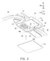
- FIG. 3 is a partial schematic view of the heat dissipation module of FIG. 1 , such that an internal structure thereof can be successfully identified by partially disassembling the evaporator 110.
- FIG. 4 is a partial sectional view of the evaporator of FIG. 3 . Referring to both of FIG. 3 and FIG. 4 , in the present embodiment, the second end E2 of the heat pipe 130 substantially fills up the recess 112.
- the heat pipe 130 is structurally contacted to walls W1, W2 at the recess 112 of the evaporator 110, so that a thermal contact area of the heat pipe 130 and the evaporator 110 is increased, and a heat conduction efficiency is effectively increased due to a compact disposition of the heat pipe 130 and the evaporator 110 (i.e., the walls W1, W2 can be served as heat conducting walls of the evaporator 110.)
- a top surface S2 of the heat pipe 130 is coplanar with the exterior surface S1 of the evaporator 110 because of the compact disposition of the aforementioned heat pipe 130 and the evaporator 110 at the exterior surface S1 of the evaporator 110.
- this configuration can also increase a disposition efficiency of the heat dissipation module 100 and surrounding elements thereof in the electronic device 10, i.e., a space utilization efficiency in the electronic device 10 is increased.
- portions of the evaporator 110 at the walls W1, W2 are the thinnest of the whole structure thereof, such that the evaporator 110 in the present embodiment can efficiently absorb a heat from the second end E2 of the heat pipe 130. That is, thickness of the walls W1, W2 is smaller than that of the other walls of the evaporator 110, e.g., a thickness t1 and a thickness t2 are substantially smaller than a thickness t4 and a thickness t5.
- the second end E2 of the heat pipe 130 is disposed compactly with the recess 112 of the evaporator 110, so that the heat pipe 130 can provide a structural support to the aforementioned walls W1, W2, and thus bring about both effects of increasing heat conduction efficiency and enhancing structure strength.
- the thickness t1 and the thickness t2 can also be substantially smaller than thickness t3, t4 and t5. Similarly, by applying the thickness difference, the heat of the heat pipe 130 can be transfer to the evaporator 110 through the walls with smaller thickness.
- the evaporator 110 is substantially formed by assembling a main body 111 and a cover body 113, in order to form an inner space that the working fluid F1 flows therein, wherein the main body 111 has openings E3, E4 connecting to the pipe 120 that the working fluid F1 flows in or out thereby (The flow direction of the working fluid F1 are presented by the arrows in the figures, but it is not limited thereby. In another embodiment not being illustrated, the working fluid can also flow in a reversed direction.)
- the main body 111 has the aforementioned recess 112 and thus forms a protrusion in the inner space thereof.
- the inner space of the evaporator 110 thus can be separated into a flowing region R2 and a heating region R1, wherein the protrusion thereof is the heating region R1, and a region thereof connected to the pipe 120 and the openings E3, E4 is the flowing region R2. Further illustration will be given below.
- the heat dissipation module 110 further comprises a plurality of heat conducting components 140, which are disposed in the heating region R1 and located on the wall W1 corresponding to the recess 112.
- the plurality of heat conducting components 140 are in pillar shape and arrayed on the wall W1. That is, when the working fluid F1 flows from the opening E3 to the heating region R1 of the evaporator 110, a heat exchange efficiency of the working fluid F1 and the walls W1, W2 can be increased.
- the heat of the walls W1, W2 connected to the heat pipe 130 is more efficiently exchanged through the heat conducting components 140 extended from the wall W1, so that the working fluid F1 in liquid absorbs the heat and is transformed to the working fluid F1 in vapor, and flows into the pipe 120 through the opening E4.
- the pipe 120 is substantially disposed around the plate body 500. That is, in the present embodiment, the plate body 500 further comprises a plurality of side protrusions 540. At least a portion of the pipe 120 is substantially contacted to the side protrusions 540, wherein a formation method of the contact is not limited here, it can be performed by welding. In other words, all methods, which can form thermal contact between the pipe 120 and the plate body 500 to efficiently transfer the heat from the evaporator 110 to the plate body 500, are suitable in the present embodiment. Accordingly, the working fluid F 1 in the evaporator 110 absorbs the heat and is transformed to vapor from liquid, and is collected and transferred to the pipe 120.
- the plate body 500 When the working fluid F1 in vapor is transferred to where the pipe 120 is thermally contacted to the plate body 500, the plate body 500 thus can absorb the heat, in order to provide a condensation effect to the working fluid F1. Therefore, the working fluid F1 in vapor is transformed back to liquid, and can be transferred back to the evaporator 110 through the pipe 120.
- an improved heat conduction efficiency is provided due to properties of the plate body 500, which include larger area and material properties of metal. Accordingly, the working fluid F1 in vapor can attain the condensation effect while passing through the plate body 500 along with the pipe 120, such that the working fluid F1 in vapor is transformed back to the working fluid F1 in liquid and returned to the evaporator 110 again through the opening E3.
- each of the heat conducting components 140 is contacted between the wall W1 of the main body 111 and the cover body 113.
- the heat conducting components 140 can also serve as a support structure thereof, in order to avoid a deformation of the inner space of the evaporator 110 resulted from improper assembly.
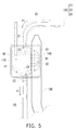
- FIG. 5 is a top view illustrating the heat dissipation module of FIG. 3 .
- a structure of a connection portion between the inner space of the evaporator 110 and pipe 120 presents a profile gradually converging towards the pipe 120 in relation to other structure of the inner space.
- the inner space of the evaporator 110 further includes a first guiding surface U1, a second guiding surface U2 and the third guiding surface U3 located at the periphery of the inner space respectively, wherein the first guiding surface U1 and the second guiding surface U2 are gradually converging from the inner space towards the pipe 120 (namely, the opening E4) while the third guiding surface U3 is gradually converging from the inner space towards the pipe 120 (namely, the opening E3), and gradually converging directions for the two profiles are opposite to each other.
- first guiding surface U1 and the second guiding surface U2 are located at two opposite sides of the opening E4 and are tilted towards the opening E4, while the third guiding surface U3 is adjacent to the opening E3 and is tilted towards the opening E3.
- the second guiding surface U2 and the third guiding surface U3 are located at the heating region R1
- the first guiding surface is located at the flowing region R2
- the heat conducting components 140 disposed at the heating region R1 is located between the second and the third guiding surfaces.
- the working fluid F1 when the working fluid F1 flows into the inner space of the evaporator 110 through the opening E3, the flow direction thereof will produce a jet stream effect due to a sudden open space formed by the third guiding surface U3, as shown by the dashed-arrows in FIG. 3 .
- the working fluid F1 absorbs the heat mainly through the heat conducting components 140 and a phase transformation is occurred (the working fluid F1 transforms from liquid state to vapor state), and after being converged by the gradually converging profile formed by the first guiding surface U1 and the second guiding surface U2, the working fluid F1 then flows into the pipe 120 through the opening E4.
- the present embodiment does not intend to limit the number of guiding surfaces at the two sides of the chamber within the evaporator 110 and their degree of tilt. That is, those skilled in the art should be able to dispose a proper number of guide surfaces at the two openings of the inner space according to the characteristics of the working fluid and the heat dissipation requirements thereof so as to form the structures that gradually converge towards the pipe.
- the pipe 120 of the present embodiment is substantially divided into a main segment E5 and two end portions E1, E2, wherein the main segment E5 is located between the end portions E1, E2, and the pipe 120 is connected with the openings E3, E4 of the evaporator 110 through the end portions E1, E2 thereof (e.g., the end portion E1 connects to the opening E3, and the end portion E2 connects to the opening E4).
- the end portions E1, E2 of the pipe 120 has a structure gradually converging towards the evaporator 110.
- a size relationship between the pipe 120 and the inner space of the evaporator 110 of the present embodiment is that: a pipe diameter of the main segment E5 is substantially greater than or equal to a thickness of the inner space of the evaporator 110, and the thickness of the inner space of the evaporator 110 is greater than a pipe diameter of each of the end portions E1, E2.
- the working fluid F1 can maintain a larger flow and a lower pipeline loss at the main segment E5, and when the working fluid F1 flows from the end portion E1 or E2 into the evaporator 110, through using the gradually converging pipe diameter in collaboration with the gradually converging structure of the inner space of the evaporator 110 (which is a gradually diverging profile to the working fluid F1), the jet stream effect can enhance the working fluid F1 to be uniformly sprayed to every part of the inner space.
- the invention does not limit the flow direction of the working fluid, that is, the heat dissipation module 100 of the present embodiment can enable the working fluid F1 to flow towards different directions in correspondence to a use state of the electronic device 10, and can also enable the working fluid F1 to maintain its flow volume and flow rate regardless of any direction through using the gradually converging pipe diameters of the two end portions E1, E2 of the pipe 120, and thereby achieves the jet stream effect.
- the main segment E5 is substantially thermally contacting with the plate body 500, and thus, with the feature that the plate body 500 has a larger area and is made of metal material, a favorable heat transfer effect can be provided so as to enable the vapor state working fluid F1 to attain a condensation effect when flowing through the main segment E5 of the pipe 120 from end portion E2 or E1, so that the vapor state working fluid F1 can be transformed back into the liquid state working fluid F1 and flows into the evaporator 110 through the end portion E1 or E2, again.
- FIG. 6 is a partial sectional view illustrating an evaporator in another embodiment of the present invention.
- heat conducting components 640 in the present embodiment are in rib shape, and an extending direction thereof is oriented in a flow direction of the working fluid F1. This configuration can also attain the aforementioned effects of support and heat conduction.
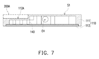
- FIG. 7 is a sectional view illustrating the evaporator in another embodiment of the present invention.
- a heat source 200A in the present embodiment is directly contacted to a recess 112A of an evaporator 110A, so that a heat generated from the heat source 200A can be more directly transferred to the evaporator 110A.
- the other structure of the present embodiment can be known by the aforementioned embodiments, so that they are omitted here.
- FIG. 8 is a partial exploded view of an electronic device according to another embodiment of the present invention.
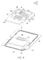
- FIG. 9 is a schematic view of the heat dissipation module of FIG. 8 .
- FIG. 10 and FIG. 11 are respective sectional views taken along the line A-A' and line B-B'. Referring FIG. 8 to FIG. 11 , a part of the present embodiment that is the same as the aforementioned embodiments, this includes that a configuration of relative elements of the electronic device 20 is the same as that of the aforementioned electronic device 10.
- most elements of a heat dissipation module 600 such as the heat conducting sheet 170, the heat pipe 130, the evaporator 110 and the pipe 120 are the same as those of the aforementioned embodiments.
- the heat conducing pads 241 between the pipe 120 and the casing 310 are merely different in appearance that do not affect their function. In other words, the heat transfer paths of the aforementioned embodiments can also be realized in the present embodiment.
- a plate body 630 not only provides the aforementioned EMI shielding effect, and is contacted to the heat conducting sheet 170, the evaporator 110 and the pipe 120 to provide the corresponding condensation effect, but also has an inner space 631 to be a hollow plate body.
- a block wall 640 and a plurality of heating pillars 620 are disposed in the inner space 631, wherein the block wall 640 separates the inner space 631 into a heating region R3 and a condensation region R4.
- Heating pillars 620 are stood in the heating region R3, and a plurality of channels 610 are disposed in the condensation region R4 by disposing a plurality of block-wall-like structures parallel to each other in the condensation region R4.
- a working fluid F2 is filled in the inner space 631 to flow between the heating region R3 and the condensation region R4.
- the heating region R3 is substantially and correspondingly contacted and stacked on the heat conducting sheet 170 and a heat absorbing end of the heat pipe 130 on the heat source 200 (i.e., the electronic module). Accordingly, the heating region R3 thus can absorb the heat generated from the heat source 200 (i.e., the electronic module) and further heat the working fluid F2 in liquid therein, in order to transform the working fluid F2 to vapor. Such that, the working fluid F2 in vapor can be guided, and flow to the condensation region R4 along with the block wall 640. Afterwards, as shown in FIG.
- the heat conducting pads 241 are sandwiched between the plate body 630 of the heat dissipation module 600 and the casing 310, so that the working fluid F2 in the condensation region R4 can transfer the heat to the casing 310 through the heat conducting pads 241, so that the heat is then dissipated away from the electronic device 20.
- the working fluid F2 in vapor in the channels 610 is gradually condensed to liquid, and then flows back to the heating region R3 again.
- the heating region R3 appears to be under the condensation region R4 of the inner space 631 in the plate body 630.
- the channels 610 in the condensation region R4 substantially appear to be extending along with a direction from upper left to lower right, thus the working fluid F2 can be circulated more efficiently in the inner space 631, and properties of the working fluid F2 is better exploited to attain higher working efficiency.
- the block wall 640 further comprises backflow prevention part 641 at where the working fluid F2 flows back from the condensation region R4 to the heating region R3.
- the backflow prevention part 641 is extended from the condensation region R4 toward the heating region R3, in order to serve as a guiding structure that guides the working fluid F2 in liquid to flow back to the heating region R3, and also avoid the working fluid F2 in vapor from flowing from the heating region R3 to the condensation region R4, which disrupts a fluid circulation.
- the channels 610 shown in FIG. 9 can also be disposed at two opposite sides of the heating pillars 620 at the same time.
- the channels 610 shown in FIG. 9 are further disposed at the opposite side of the heating pillars 620, so that the heating region R3 is located between two condensation regions R4.
- This configuration can attain an effect of circulation of the working fluid F2 through the heating pillar 620 and the channels 610 in the inner space 631 of the plate body 630, while the electronic device 20 is used with different angles. That is, appropriate number of the condensation regions R4 can be disposed around the heating region R3 by users according to their requirements.
- the plate body 630 can realize a heat dissipation efficiency in correspondence to different usage states of the electronic device 20, in order to improve an applicability of the heat dissipation effect of the plate body 630.
- a heat dissipation module is thermally contacted to a heat source through a recess of an evaporator, to absorb a heat generated from the heat source effectively according to the structure of appearance thereof.
- an effect of compact disposition of the structure of the heat dissipation module is attained, so that elements in the electronic device can be better disposed, and a space utilization efficiency in the electronic device is improved.
- thickness of walls at the recess of the evaporator is smaller than thickness of the other walls of the evaporator, which is beneficial for transferring the heat to a working fluid in an inner space of the evaporator.
- a plurality of heat conduction components are disposed in the inner space of the evaporator corresponding to the recess, in order to increase a heat conduction area and a heat conduction efficiency between the evaporator and the working fluid.
- the heat generated from the heat source is transferred to the evaporator through a heat pipe, and the recess is substantially filled up by the heat pipe. Therefore, a structure strength at the recess of the evaporator is improved, and it is beneficial for designers to dispose elements in the electronic device according to a compact disposition of the heat pipe and the evaporator.
- the heat pipe and a pipe of the heat dissipation module can be contacted to a plate body of the electronic device, so that the heat is uniformly transferred to all over the plate body and the heat dissipation module through the plate body, which is advantageous to dissipate the heat.
Landscapes
- Engineering & Computer Science (AREA)
- Physics & Mathematics (AREA)
- General Engineering & Computer Science (AREA)
- Thermal Sciences (AREA)
- Mechanical Engineering (AREA)
- Theoretical Computer Science (AREA)
- Life Sciences & Earth Sciences (AREA)
- Sustainable Development (AREA)
- Microelectronics & Electronic Packaging (AREA)
- Computer Hardware Design (AREA)
- Human Computer Interaction (AREA)
- General Physics & Mathematics (AREA)
- Geometry (AREA)
- Cooling Or The Like Of Electrical Apparatus (AREA)
- Cooling Or The Like Of Semiconductors Or Solid State Devices (AREA)
Abstract
Description
- The present invention relates to a heat dissipation module.
- With the increasing development of hi-tech industry, mobile devices such as mobile phones and tablet PCs have become one of the most indispensable necessities of our daily life. As people become growingly rely on the mobile devices, usages times are also getting longer and longer. However, prolonged use of the mobile devices usually causes the integrated circuits of the mobile devices to crash due to overheating, and thereby is very inconvenient.
- As the mobile phones or the tablet PCs are restricted by the size and weight requirements and are unable to use a fan as a heat dissipation means. A conventional method of heat dissipation is to attach a heat dissipation material thereon or to use a heat pipe. Nevertheless, under the operation of high power electronic components within the mobile devices, a heat dissipation efficiency provided by the aforesaid heat dissipation method is still very limited.
- The present invention provides a heat dissipation module, having a compact structure disposition and improved heat dissipation efficiency.
- The heat dissipation module of the present invention is suitable for an electronic device. The electronic device has a heat source. The heat dissipation module includes an evaporator, a pipe, and a working fluid. The evaporator has a recess at an exterior surface of the evaporator, and the heat source is thermally contacted with the recess to transfer a heat generated from the heat source to the recess of the evaporator. The pipe is connected to an inner space of the evaporator and forms a loop. The working fluid is filled in the loop, wherein the working fluid in liquid passing through a portion of the inner space of the evaporator corresponding to the recess absorbs the heat and is transformed to vapor.
- In view of above, in the aforementioned embodiment of the present invention, through a structural characteristic of the evaporator of the heat dissipation module, i.e., having the recess at the exterior surface thereof, to thermally contact the heat source of the electronic device. Thus, the structural characteristic of the recess can increase a thermal contact area between the heat source and the evaporator. In addition, the pipe can be filled with the working fluid after being connected to the evaporator to form a loop, such that the working fluid can efficiently absorb heat while passing through the inner space of the evaporator corresponding to the aforesaid recess. Thus, the working fluid transforms to vapor and carries away the heat by flowing away from the inner space of the evaporator, to attain a heat dissipation effect.
- To make the above features and advantages of the invention more comprehensible, several embodiments accompanied with drawings are described in detail as follows.
-
-
FIG. 1 is a partial exploded view of an electronic device according to an embodiment of the present invention. -
FIG. 2 is an exploded view of the electronic device ofFIG. 1 . -
FIG. 3 is a partial schematic view of the heat dissipation module ofFIG. 1 . -
FIG. 4 is a partial sectional view of the evaporator ofFIG. 3 . -
FIG. 5 is a top view illustrating the heat dissipation module ofFIG. 3 . -
FIG. 6 is a partial sectional view illustrating an evaporator in another embodiment of the present invention. -
FIG. 7 is a sectional view illustrating the evaporator in another embodiment of the present invention. -
FIG. 8 is a partial exploded view of an electronic device according to another embodiment of the present invention. -
FIG. 9 is a schematic view of the heat dissipation module ofFIG. 7 . -
FIG. 10 andFIG. 11 are respective sectional views taken along the line A-A' and line B-B'. - Reference will now be made in detail to the present preferred embodiments of the invention, examples of which are illustrated in the accompanying drawings. Wherever possible, the same reference numbers are used in the drawings and the description to refer to the same or like parts.
-
FIG. 1 is a partial exploded view of an electronic device according to an embodiment of the present invention. Referring toFIG. 1 , in the present embodiment,electronic device 10 is, for example, a portable electronic device such as a notebook computer or a tablet PC, which has a slim and light appearance for complying with demands of convenient carrying. Nevertheless, with increasing demands in computation and display, anelectronic device 10 has to be disposed with relative components having a heat dissipation effect incasings electronic device 10 includes aheat source 200 and a heat dissipation module 100, wherein theheat source 200 is, for example, an electronic module such as a central processor or a display chip, and the heat dissipation module 100 can absorb a heat generated from theheat source 200 and can dissipate the heat from the other parts of theelectronic device 10. - In the present embodiment, the heat dissipation module 100 is, for example, a siphon type heat dissipation component, which includes an
evaporator 110, apipe 120 and a working fluid F1 (only arrows representing a flow direction thereof are provided in the drawing). Theevaporator 110 is configured to thermally contact theheat source 200, so as to absorb the heat from theheat source 200. Thepipe 120 is connected to theevaporator 110 to form a loop, and the working fluid F1 is filled in the loop. When flowing through theevaporator 110, a phase transformation of the working fluid F1 is occurred via heat absorption or dissipation. For example, the working fluid F1 transforms from liquid to vapor by absorbing the heat, and then transforms to liquid again after heat dissipation. The vapor state working fluid F1 moves away from theevaporator 110 to carry away the heat and flows through the other parts of theelectronic device 10 with lower temperature along with thepipe 120, in order to enable the working fluid F1 to undergo a phase change condensation (transforming from the vapor state back to the liquid state). Thus, the heat is able to be dissipated away from theelectronic device 10. - In detail, the heat dissipation module 100 of the present embodiment further comprises a
heat pipe 130, which is thermally contacted between theheat source 200 and theevaporator 110 to transfer the heat generated from theheat source 200 to theevaporator 110. Further speaking, as shown inFIG. 1 , a first end E1 of theheat pipe 130 is clasped on aplate body 500 of theelectronic device 10 and structurally contacted on theheat source 200 by theclasp members 400. A second end E2 of theheat pipe 130 is structurally contacted to theevaporator 110 by welding, and is substantially contacted to arecess 112 of a portion of an exterior surface S1 of theevaporator 110. Therefore, theheat pipe 130 can transfer the heat generated from theheat source 200 to therecess 112 of theevaporator 110 through a phase transition of another working fluid therein. It is worth noting that, as the disposition shown inFIG. 1 , theelectronic device 10 in the present embodiment can provide certain heat dissipation effect to theheat source 200 through theplate body 500, i.e., the heat is uniformly distributed to all over theplate body 500 and the heat dissipation module 100 by contacting theheat pipe 130 and thepipe 120 to theplate body 500 together. In other embodiments not being illustrated, theplate body 500 can also be a partial structure or whole structure of thecasings plate body 500 is made of metal material, so that it can also provide an electromagnetic interference (EMI) shielding effect to the heat source 200 (such as the aforementioned central processor or display chip.) -
FIG. 2 is an exploded view of the electronic device ofFIG. 1 to illustrate the other elements not shown inFIG.1 . Referring both ofFIG. 1 andFIG. 2 , further speaking, in the present embodiment, theplate body 500 is assembled to acircuit board 210 via protrusion structures ( elements such as fasten components that are known in prior art are omitted here.) The heat dissipation module 100 further comprises aheat conducting sheet 170 is contacted to the heat source 200 (i.e., the electronic module) and substantially located between theplate body 500 and the heat source 200 (i.e., the electronic module), so that a portion of the heat generated from the heat source 200 (i.e., the electronic module) can be transferred to theplate body 500 through theheat conducting sheet 170. Herein, theheat conducting sheet 170 has a recessedmain body 174 and anopening 172, and the heat dissipation module 100 further comprises a heat conductingpad 243 and aheat conducting glue 242. The recessedmain body 174 of theheat conducting sheet 170 is contacted to the heat source 200 (i.e., the electronic module) through theheat conducting glue 242, and can expose theplate body 500 through anopening 510, so that a portion of theheat pipe 130 is supported on the recessedmain body 174. The heat conductingpad 243 is passed through theopening 172 and contacted to theheat pipe 130 disposed at the recessedmain body 174. In addition, a central portion of theclasp members 400 are contacted to theplate body 500, and an end of theclasp members 400 is passed through the opening 520 of theplate body 500 and assembled to the circuit board 210 (as the resultant structure shown inFIG.2 , but the form thereof is not limited here), so that forming a state that theheat conducting sheet 170 and theplate body 500 are clasped between theclasp members 400 and thecircuit board 210. Thus, theheat conducting sheet 170 and theplate body 500 can be more tightly contacted to the heat source 200 (i.e., the electronic module) through the heat conductingpad 243. - The
heat pipe 130 is disposed at thetrench 530 of theplate body 500, and the first end E1 of theheat pipe 130 is thermally contacted to the heat source 200 (i.e., the electronic module), and the second end E2 of theheat pipe 130 is thermally contacted to theevaporator 110. Therefore, another portion of the heat generated from the heat source 200 (i.e., the electronic module) is transferred to theevaporator 110 through theheat pipe 130. - Accordingly, a portion of the heat generated from the heat source 200 (i.e., the electronic module) is sequentially transferred to the
plate body 500 through theheat conducting glue 242 and theheat conducting sheet 170, and another portion of the heat is transferred to theheat pipe 130 through the heat conductingpad 243, wherein the aforementioned heat transfer paths are close to each other and located at the first end E1 of theheat pipe 130. Thus, the heat transferred to theplate body 500 can also provide a heating effect to theheat pipe 130 because of structural contact thereof. As a result, a portion of the heat generated from the heat source 200 (i.e., the electronic module) can be dissipated through theplate body 500, i.e., theplate body 500 can provide not only an EMI shielding effect by covering the heat source 200 (i.e., the electronic module), but a heat dissipation effect due to properties of the material (such as metal) thereof and relatively large area (compared to the other elements.) - In addition, as shown in
FIG. 1 , the heat dissipation module 100 can also be further contacted to thecasing 310 through the heat conducting (241 disposed on theplate body 500. Such that, the heat on theplate body 500 can be further transferred to thecasing 310 to attain an effect of dissipating heat away from theelectronic device 10. -
FIG. 3 is a partial schematic view of the heat dissipation module ofFIG. 1 , such that an internal structure thereof can be successfully identified by partially disassembling theevaporator 110.FIG. 4 is a partial sectional view of the evaporator ofFIG. 3 . Referring to both ofFIG. 3 andFIG. 4 , in the present embodiment, the second end E2 of theheat pipe 130 substantially fills up therecess 112. That is, theheat pipe 130 is structurally contacted to walls W1, W2 at therecess 112 of theevaporator 110, so that a thermal contact area of theheat pipe 130 and theevaporator 110 is increased, and a heat conduction efficiency is effectively increased due to a compact disposition of theheat pipe 130 and the evaporator 110 (i.e., the walls W1, W2 can be served as heat conducting walls of theevaporator 110.) - Moreover, a top surface S2 of the
heat pipe 130 is coplanar with the exterior surface S1 of theevaporator 110 because of the compact disposition of theaforementioned heat pipe 130 and theevaporator 110 at the exterior surface S1 of theevaporator 110. As a result, in consideration of structure disposition, this configuration can also increase a disposition efficiency of the heat dissipation module 100 and surrounding elements thereof in theelectronic device 10, i.e., a space utilization efficiency in theelectronic device 10 is increased. - As shown in
FIG. 4 , portions of theevaporator 110 at the walls W1, W2 are the thinnest of the whole structure thereof, such that theevaporator 110 in the present embodiment can efficiently absorb a heat from the second end E2 of theheat pipe 130. That is, thickness of the walls W1, W2 is smaller than that of the other walls of theevaporator 110, e.g., a thickness t1 and a thickness t2 are substantially smaller than a thickness t4 and a thickness t5. In addition, the second end E2 of theheat pipe 130 is disposed compactly with therecess 112 of theevaporator 110, so that theheat pipe 130 can provide a structural support to the aforementioned walls W1, W2, and thus bring about both effects of increasing heat conduction efficiency and enhancing structure strength. Besides, in another embodiment not being illustrated, the thickness t1 and the thickness t2 can also be substantially smaller than thickness t3, t4 and t5. Similarly, by applying the thickness difference, the heat of theheat pipe 130 can be transfer to theevaporator 110 through the walls with smaller thickness. - As shown in
FIG. 3 andFIG. 4 , theevaporator 110 is substantially formed by assembling amain body 111 and acover body 113, in order to form an inner space that the working fluid F1 flows therein, wherein themain body 111 has openings E3, E4 connecting to thepipe 120 that the working fluid F1 flows in or out thereby (The flow direction of the working fluid F1 are presented by the arrows in the figures, but it is not limited thereby. In another embodiment not being illustrated, the working fluid can also flow in a reversed direction.) In addition, themain body 111 has theaforementioned recess 112 and thus forms a protrusion in the inner space thereof. Further speaking, the inner space of theevaporator 110 thus can be separated into a flowing region R2 and a heating region R1, wherein the protrusion thereof is the heating region R1, and a region thereof connected to thepipe 120 and the openings E3, E4 is the flowing region R2. Further illustration will be given below. - In the present embodiment, the
heat dissipation module 110 further comprises a plurality ofheat conducting components 140, which are disposed in the heating region R1 and located on the wall W1 corresponding to therecess 112. Herein, the plurality ofheat conducting components 140 are in pillar shape and arrayed on the wall W1. That is, when the working fluid F1 flows from the opening E3 to the heating region R1 of theevaporator 110, a heat exchange efficiency of the working fluid F1 and the walls W1, W2 can be increased. The heat of the walls W1, W2 connected to theheat pipe 130 is more efficiently exchanged through theheat conducting components 140 extended from the wall W1, so that the working fluid F1 in liquid absorbs the heat and is transformed to the working fluid F1 in vapor, and flows into thepipe 120 through the opening E4. - It is worth noting that, as the structure disposition shown in
FIG. 1 , thepipe 120 is substantially disposed around theplate body 500. That is, in the present embodiment, theplate body 500 further comprises a plurality ofside protrusions 540. At least a portion of thepipe 120 is substantially contacted to theside protrusions 540, wherein a formation method of the contact is not limited here, it can be performed by welding. In other words, all methods, which can form thermal contact between thepipe 120 and theplate body 500 to efficiently transfer the heat from theevaporator 110 to theplate body 500, are suitable in the present embodiment. Accordingly, the workingfluid F 1 in theevaporator 110 absorbs the heat and is transformed to vapor from liquid, and is collected and transferred to thepipe 120. When the working fluid F1 in vapor is transferred to where thepipe 120 is thermally contacted to theplate body 500, theplate body 500 thus can absorb the heat, in order to provide a condensation effect to the working fluid F1. Therefore, the working fluid F1 in vapor is transformed back to liquid, and can be transferred back to theevaporator 110 through thepipe 120. Herein, an improved heat conduction efficiency is provided due to properties of theplate body 500, which include larger area and material properties of metal. Accordingly, the working fluid F1 in vapor can attain the condensation effect while passing through theplate body 500 along with thepipe 120, such that the working fluid F1 in vapor is transformed back to the working fluid F1 in liquid and returned to theevaporator 110 again through the opening E3. - Moreover, in the
evaporator 110, each of theheat conducting components 140 is contacted between the wall W1 of themain body 111 and thecover body 113. Thus, during the assembly of themain body 111 and thecover body 113, theheat conducting components 140 can also serve as a support structure thereof, in order to avoid a deformation of the inner space of theevaporator 110 resulted from improper assembly. -
FIG. 5 is a top view illustrating the heat dissipation module ofFIG. 3 . Referring toFIGs. 3 and5 , a structure of a connection portion between the inner space of theevaporator 110 andpipe 120 presents a profile gradually converging towards thepipe 120 in relation to other structure of the inner space. Further speaking, the inner space of theevaporator 110 further includes a first guiding surface U1, a second guiding surface U2 and the third guiding surface U3 located at the periphery of the inner space respectively, wherein the first guiding surface U1 and the second guiding surface U2 are gradually converging from the inner space towards the pipe 120 (namely, the opening E4) while the third guiding surface U3 is gradually converging from the inner space towards the pipe 120 (namely, the opening E3), and gradually converging directions for the two profiles are opposite to each other. In other words, the first guiding surface U1 and the second guiding surface U2 are located at two opposite sides of the opening E4 and are tilted towards the opening E4, while the third guiding surface U3 is adjacent to the opening E3 and is tilted towards the opening E3. - Besides, the second guiding surface U2 and the third guiding surface U3 are located at the heating region R1, the first guiding surface is located at the flowing region R2, and the
heat conducting components 140 disposed at the heating region R1 is located between the second and the third guiding surfaces. - In view of the above, when the working fluid F1 flows into the inner space of the
evaporator 110 through the opening E3, the flow direction thereof will produce a jet stream effect due to a sudden open space formed by the third guiding surface U3, as shown by the dashed-arrows inFIG. 3 . Next, the working fluid F1 absorbs the heat mainly through theheat conducting components 140 and a phase transformation is occurred (the working fluid F1 transforms from liquid state to vapor state), and after being converged by the gradually converging profile formed by the first guiding surface U1 and the second guiding surface U2, the working fluid F1 then flows into thepipe 120 through the opening E4. - It is to be mentioned that, although as shown in the present embodiment, only the third guiding surface U3 is located at the opening E3 while the first guiding surface U1 and second guiding surface U2 are located at the opening E4, the present embodiment does not intend to limit the number of guiding surfaces at the two sides of the chamber within the
evaporator 110 and their degree of tilt. That is, those skilled in the art should be able to dispose a proper number of guide surfaces at the two openings of the inner space according to the characteristics of the working fluid and the heat dissipation requirements thereof so as to form the structures that gradually converge towards the pipe. - On the other hand, the
pipe 120 of the present embodiment is substantially divided into a main segment E5 and two end portions E1, E2, wherein the main segment E5 is located between the end portions E1, E2, and thepipe 120 is connected with the openings E3, E4 of theevaporator 110 through the end portions E1, E2 thereof (e.g., the end portion E1 connects to the opening E3, and the end portion E2 connects to the opening E4). Herein, it is to be noted that, at least one of the end portions E1, E2 of thepipe 120 has a structure gradually converging towards theevaporator 110. In other words, a size relationship between thepipe 120 and the inner space of theevaporator 110 of the present embodiment is that: a pipe diameter of the main segment E5 is substantially greater than or equal to a thickness of the inner space of theevaporator 110, and the thickness of the inner space of theevaporator 110 is greater than a pipe diameter of each of the end portions E1, E2. - As a result, since the main segment E5 has a pipe diameter relatively greater than that of the end portions E1, E2, the working fluid F1 can maintain a larger flow and a lower pipeline loss at the main segment E5, and when the working fluid F1 flows from the end portion E1 or E2 into the
evaporator 110, through using the gradually converging pipe diameter in collaboration with the gradually converging structure of the inner space of the evaporator 110 (which is a gradually diverging profile to the working fluid F1), the jet stream effect can enhance the working fluid F1 to be uniformly sprayed to every part of the inner space. As previously described, the invention does not limit the flow direction of the working fluid, that is, the heat dissipation module 100 of the present embodiment can enable the working fluid F1 to flow towards different directions in correspondence to a use state of theelectronic device 10, and can also enable the working fluid F1 to maintain its flow volume and flow rate regardless of any direction through using the gradually converging pipe diameters of the two end portions E1, E2 of thepipe 120, and thereby achieves the jet stream effect. - Furthermore, the main segment E5 is substantially thermally contacting with the
plate body 500, and thus, with the feature that theplate body 500 has a larger area and is made of metal material, a favorable heat transfer effect can be provided so as to enable the vapor state working fluid F1 to attain a condensation effect when flowing through the main segment E5 of thepipe 120 from end portion E2 or E1, so that the vapor state working fluid F1 can be transformed back into the liquid state working fluid F1 and flows into theevaporator 110 through the end portion E1 or E2, again. -
FIG. 6 is a partial sectional view illustrating an evaporator in another embodiment of the present invention. Referring toFIG. 6 , the difference from the aforementioned embodiment is thatheat conducting components 640 in the present embodiment are in rib shape, and an extending direction thereof is oriented in a flow direction of the working fluid F1. This configuration can also attain the aforementioned effects of support and heat conduction. -
FIG. 7 is a sectional view illustrating the evaporator in another embodiment of the present invention. The difference from the aforementioned embodiments is that aheat source 200A in the present embodiment is directly contacted to arecess 112A of an evaporator 110A, so that a heat generated from theheat source 200A can be more directly transferred to the evaporator 110A. The other structure of the present embodiment can be known by the aforementioned embodiments, so that they are omitted here. -
FIG. 8 is a partial exploded view of an electronic device according to another embodiment of the present invention.FIG. 9 is a schematic view of the heat dissipation module ofFIG. 8 .FIG. 10 andFIG. 11 are respective sectional views taken along the line A-A' and line B-B'. ReferringFIG. 8 to FIG. 11 , a part of the present embodiment that is the same as the aforementioned embodiments, this includes that a configuration of relative elements of the electronic device 20 is the same as that of the aforementionedelectronic device 10. Besides, most elements of aheat dissipation module 600, such as theheat conducting sheet 170, theheat pipe 130, theevaporator 110 and thepipe 120 are the same as those of the aforementioned embodiments. Besides, theheat conducing pads 241 between thepipe 120 and thecasing 310, are merely different in appearance that do not affect their function. In other words, the heat transfer paths of the aforementioned embodiments can also be realized in the present embodiment. - Another part of the present embodiment that is different to the aforementioned embodiments is described below. A
plate body 630 not only provides the aforementioned EMI shielding effect, and is contacted to theheat conducting sheet 170, theevaporator 110 and thepipe 120 to provide the corresponding condensation effect, but also has aninner space 631 to be a hollow plate body. Besides, ablock wall 640 and a plurality ofheating pillars 620 are disposed in theinner space 631, wherein theblock wall 640 separates theinner space 631 into a heating region R3 and a condensation region R4.Heating pillars 620 are stood in the heating region R3, and a plurality ofchannels 610 are disposed in the condensation region R4 by disposing a plurality of block-wall-like structures parallel to each other in the condensation region R4. A working fluid F2 is filled in theinner space 631 to flow between the heating region R3 and the condensation region R4. - It is worth noting that, as shown in
FIG. 9 , as theplate body 640 covers thecircuit board 210 to shield the heat source 200 (i.e., the electronic module), the heating region R3 is substantially and correspondingly contacted and stacked on theheat conducting sheet 170 and a heat absorbing end of theheat pipe 130 on the heat source 200 (i.e., the electronic module). Accordingly, the heating region R3 thus can absorb the heat generated from the heat source 200 (i.e., the electronic module) and further heat the working fluid F2 in liquid therein, in order to transform the working fluid F2 to vapor. Such that, the working fluid F2 in vapor can be guided, and flow to the condensation region R4 along with theblock wall 640. Afterwards, as shown inFIG. 8 , theheat conducting pads 241 are sandwiched between theplate body 630 of theheat dissipation module 600 and thecasing 310, so that the working fluid F2 in the condensation region R4 can transfer the heat to thecasing 310 through theheat conducting pads 241, so that the heat is then dissipated away from the electronic device 20. Thus, the working fluid F2 in vapor in thechannels 610 is gradually condensed to liquid, and then flows back to the heating region R3 again. - It is worth noting that, when the electronic device 20 is placed at certain positions to be, for example, in a standing state, the heating region R3 appears to be under the condensation region R4 of the
inner space 631 in theplate body 630. In this case, thechannels 610 in the condensation region R4 substantially appear to be extending along with a direction from upper left to lower right, thus the working fluid F2 can be circulated more efficiently in theinner space 631, and properties of the working fluid F2 is better exploited to attain higher working efficiency. - In addition, the
block wall 640 further comprisesbackflow prevention part 641 at where the working fluid F2 flows back from the condensation region R4 to the heating region R3. Thebackflow prevention part 641 is extended from the condensation region R4 toward the heating region R3, in order to serve as a guiding structure that guides the working fluid F2 in liquid to flow back to the heating region R3, and also avoid the working fluid F2 in vapor from flowing from the heating region R3 to the condensation region R4, which disrupts a fluid circulation. - Besides, in another embodiment not being illustrated, the
channels 610 shown inFIG. 9 can also be disposed at two opposite sides of theheating pillars 620 at the same time. In other words, thechannels 610 shown inFIG. 9 are further disposed at the opposite side of theheating pillars 620, so that the heating region R3 is located between two condensation regions R4. This configuration can attain an effect of circulation of the working fluid F2 through theheating pillar 620 and thechannels 610 in theinner space 631 of theplate body 630, while the electronic device 20 is used with different angles. That is, appropriate number of the condensation regions R4 can be disposed around the heating region R3 by users according to their requirements. Such that, theplate body 630 can realize a heat dissipation efficiency in correspondence to different usage states of the electronic device 20, in order to improve an applicability of the heat dissipation effect of theplate body 630. - In view of above, in the above mentioned embodiments of the present invention, a heat dissipation module is thermally contacted to a heat source through a recess of an evaporator, to absorb a heat generated from the heat source effectively according to the structure of appearance thereof. In addition, an effect of compact disposition of the structure of the heat dissipation module is attained, so that elements in the electronic device can be better disposed, and a space utilization efficiency in the electronic device is improved. Moreover, thickness of walls at the recess of the evaporator is smaller than thickness of the other walls of the evaporator, which is beneficial for transferring the heat to a working fluid in an inner space of the evaporator. A plurality of heat conduction components are disposed in the inner space of the evaporator corresponding to the recess, in order to increase a heat conduction area and a heat conduction efficiency between the evaporator and the working fluid. In one of the embodiments, the heat generated from the heat source is transferred to the evaporator through a heat pipe, and the recess is substantially filled up by the heat pipe. Therefore, a structure strength at the recess of the evaporator is improved, and it is beneficial for designers to dispose elements in the electronic device according to a compact disposition of the heat pipe and the evaporator. Moreover, the heat pipe and a pipe of the heat dissipation module can be contacted to a plate body of the electronic device, so that the heat is uniformly transferred to all over the plate body and the heat dissipation module through the plate body, which is advantageous to dissipate the heat.
Claims (20)
- A heat dissipation module (100), which is suitable for an electronic device (10) having a heat source (200), the heat dissipation module (100) comprising:an evaporator (110) having a recess (112) at an exterior surface (S1) of the evaporator (110), wherein the heat source (200) is thermally contacted with the recess (112) to transfer a heat generated from the heat source (200) to the recess (112) of the evaporator (110);a pipe (120) connected to an inner space of the evaporator (110) to form a loop; anda first working fluid (F1) filled in the loop, wherein the first working fluid (F1) in liquid passing through a portion of the inner space of the evaporator (110) corresponding to the recess (112) absorbs the heat and is transformed to vapor.
- The heat dissipation module of claim 1, wherein the heat source (200) is structurally contacted to the recess (112) of the evaporator (110).
- The heat dissipation module of claim 1 or 2, further comprising:a heat pipe (130) thermally contacted between the heat source (200) and the evaporator (110), wherein the heat pipe (130) is structurally contacted to the recess (112) to transfer the heat from the heat source (200) to the evaporator (110).
- The heat dissipation module of claim 3, wherein the heat pipe (130) is filled up the recess (112).
- The heat dissipation module of claim 3 or 3, wherein the heat source (200) is an electronic module of the electronic device (10), the heat dissipation module (100) further comprising:a plate body (500) covering the electronic module,wherein the heat pipe (130), the evaporator (100) and the pipe (120) are thermally contacted to different portions of the plate body (500) respectively,wherein a portion of a heat generated from the electronic module is transferred to the plate body (500) through the heat pipe (130) and then dissipated and another portion of the heat generated from the electronic module is transferred to the plate body (500) through a phase transformation of the first working fluid (F1) in the evaporator (100) and the pipe (120).
- The heat dissipation module of claim 5, wherein the plate body (500) having an opening (510), the heat dissipation module (100) further comprising:a heat conducting sheet (170) disposed between the electronic module and the plate body (500), whereina portion of the heat generated from the electronic module is transferred by the heat conducting sheet (170) to the plate body (500),a part of the heat conducting sheet (170) is contacted to the heat pipe (130) through the opening (510), andanother portion of the heat generated from the electronic module is transferred to the evaporator (100) by the heat pipe (130).
- The heat dissipation module of claim 6, further comprising:a plurality of heat conducting pads (241) disposed respectively on the plate body (500), the evaporator (110), the pipe (120) and the heat conducting sheet (170), wherein the heat conducting pads (241) disposed on the plate body (500), the evaporator (110) and the pipe (120) are thermally contacted to a casing (310) of the electronic device (10).
- The heat dissipation module of claim 6 or 7, wherein the plate body (630) is a hollow plate body filled with a second working fluid (F2), and a block wall (640) is disposed therein to separate an inner space (631) of the hollow plate body into a first heating region (R3) and a condensation region (R4), wherein
the first heating region (R3) is corresponding to the heat conducting sheet (170), and
the second working fluid (F2) in liquid transforms to vapor by absorbing a heat in the first heating region (R3) and flows to the condensation region (R4) to dissipate heat and transform to liquid, then flows back to the first heating region (R3). - The heat dissipation module of claim 8, wherein the plate body (630) has a plurality of heating pillars (620) stood in the first heating region (R3).
- The heat dissipation module of claim 8 or 9, wherein the block wall (640) has a backflow prevention part (641), which is located between the first heating region (R3) and the condensation region (R4) and extended toward the first heating region (R3).
- The heat dissipation module of any of the preceding claims, wherein the evaporator (110) has a heat conducting wall (W1, W2) located at the recess (112), a thickness thereof (t1, t2) being smaller than a thickness of other walls (t3, t4, t5) of the evaporator (110).
- The heat dissipation module of any of the preceding claims, wherein the evaporator (110) has a heat conducting wall (W1) located at the recess (112), the heat dissipation module (100) further comprising:a plurality of heat conducting components (140) disposed in the evaporator (110) and located at the heat conducting wall (W1), wherein the plurality of heat conducting components (140) are in pillar shape or rib shape.
- The heat dissipation module of claim 6, wherein each of the heat conducting components in rib shape (640) is oriented in a flow direction of the working fluid (F1).
- The heat dissipation module of claim 6, wherein the evaporator (110) further comprises:a main body (111) having the recess (112); anda cover body (113) assembled to the main body (111), wherein the plurality of heat conducting components (140) are disposed in the main body (111) and contacted to the cover body (113).
- The heat dissipation module of claim 6, wherein
the inner space of the evaporator (110) is separated into a flowing region (R2) and a second heating region (R1),
the pipe (120) is connected to the flowing region (R2),
the recess (112) is corresponding to the second heating region (R1), and
the plurality of heat conducting components (140) are located in the second heating region (R1). - The heat dissipation module of any of the preceding claims, wherein a structure at a connection portion between the inner space and the pipe (120) presents a gradually converging profile towards the pipe (120) in relation to other structure of the inner space.
- The heat dissipation module of claim 16, wherein the evaporator (110) has a first opening (E3) and a second opening (E4) respectively located at two opposite sides of the inner space, wherein
two opposite ends (E1, E2) of the pipe (120) are respectively connected to the first and the second openings (E3, E4) to form the loop,
the gradually converging profile comprises a first guiding surface (U1), a second guiding surface(U2) and a third guiding surface (U3) tilting from the inner space towards each of the openings (E3, E4),
the first guiding surface (U1) and the second guiding surface (U2) are located at two opposite sides of the second opening (E4), and
the third guiding surface (U3) is adjacent to first opening (E3). - The heat dissipation module of claim 17, wherein
the inner space is divided into a heating zone (R1) and a flowing zone (R2),
the second guiding surface (U2) and the third guiding surface (U3) are located in the heating zone (R1),
the first guiding surface (U1) is located in the flowing zone (R2), and
the pipe (120) is connected to the flowing zone (R2). - The heat dissipation module of any of the preceding claims, wherein at least one of the end portions of the pipe (120) is gradually converged towards the evaporator (110).
- The heat dissipation module of claim 19, further comprising:a plate body (500) covering the heat source (200), wherein the pipe (120) includes two end portions (E1, E2) and a main segment (E5) connected therebetween, and the main segment (E5) is thermally contacted with the plate body (500),wherein a pipe diameter of the main segment (E5) is greater than or equal to a thickness of the inner space of the evaporator (110) and is greater than a pipe diameter of each of the end portions (E1, E2).
Applications Claiming Priority (3)
| Application Number | Priority Date | Filing Date | Title |
|---|---|---|---|
| TW104130535 | 2015-09-16 | ||
| TW105108930A TWI602497B (en) | 2015-09-16 | 2016-03-23 | Thermal dissipation module |
| TW105110817A TWI609163B (en) | 2015-09-16 | 2016-04-06 | Thermal module |
Publications (2)
| Publication Number | Publication Date |
|---|---|
| EP3144771A1 true EP3144771A1 (en) | 2017-03-22 |
| EP3144771B1 EP3144771B1 (en) | 2018-09-12 |
Family
ID=56925978
Family Applications (2)
| Application Number | Title | Priority Date | Filing Date |
|---|---|---|---|
| EP16185982.2A Active EP3144771B1 (en) | 2015-09-16 | 2016-08-26 | Thermal dissipation module |
| EP16186964.9A Active EP3144772B1 (en) | 2015-09-16 | 2016-09-02 | Thermal dissipation module |
Family Applications After (1)
| Application Number | Title | Priority Date | Filing Date |
|---|---|---|---|
| EP16186964.9A Active EP3144772B1 (en) | 2015-09-16 | 2016-09-02 | Thermal dissipation module |
Country Status (2)
| Country | Link |
|---|---|
| US (6) | US9835382B2 (en) |
| EP (2) | EP3144771B1 (en) |
Cited By (2)
| Publication number | Priority date | Publication date | Assignee | Title |
|---|---|---|---|---|
| EP3518072A1 (en) * | 2018-01-26 | 2019-07-31 | HTC Corporation | Heat transferring module |
| WO2022171931A1 (en) * | 2021-02-15 | 2022-08-18 | Thermal Channel Technologies Oy | Heat dissipation apparatus |
Families Citing this family (16)
| Publication number | Priority date | Publication date | Assignee | Title |
|---|---|---|---|---|
| WO2018003958A1 (en) * | 2016-07-01 | 2018-01-04 | 古河電気工業株式会社 | Heat sink structure |
| TWI635248B (en) | 2016-09-02 | 2018-09-11 | 宏碁股份有限公司 | Evaporator and manufacturing method thereof |
| EP3579673B1 (en) * | 2017-03-02 | 2022-01-26 | Huawei Technologies Co., Ltd. | Thermally-conductive component and mobile terminal |
| KR102424424B1 (en) * | 2017-03-28 | 2022-07-22 | 삼성전자주식회사 | Electronic device |
| TWI658776B (en) * | 2017-11-27 | 2019-05-01 | 宏碁股份有限公司 | Heat dissipation system of electronic device |
| TWI687642B (en) * | 2018-03-07 | 2020-03-11 | 宏碁股份有限公司 | Cycling heat dissipation module |
| CN108398994A (en) * | 2018-05-02 | 2018-08-14 | 昆山莹帆精密五金有限公司 | A kind of cpu box formula evaporator |
| CN110557931B (en) * | 2019-08-30 | 2020-12-08 | 华为技术有限公司 | In-vehicle equipment and vehicles |
| KR102954176B1 (en) | 2020-10-22 | 2026-04-17 | 삼성전자주식회사 | Semiconductor device |
| CN115151119A (en) * | 2021-03-29 | 2022-10-04 | 北京小米移动软件有限公司 | Electronic device |
| US12495526B2 (en) * | 2021-10-29 | 2025-12-09 | National Tsing Hua University | Thermal radiation heat dissipation device for electronic component and preparation method thereof |
| CN114245639B (en) * | 2021-12-16 | 2024-02-23 | Oppo广东移动通信有限公司 | Shell, shell assembly and electronic equipment |
| US11732976B1 (en) * | 2022-03-02 | 2023-08-22 | Aic Inc. | Rapid heat dissipation device |
| WO2024034854A1 (en) * | 2022-08-12 | 2024-02-15 | 엘지이노텍 주식회사 | Electronic device |
| CN121549067A (en) * | 2023-07-20 | 2026-02-17 | Lg伊诺特有限公司 | Electronic devices |
| KR20250120798A (en) * | 2024-02-02 | 2025-08-11 | 엘지이노텍 주식회사 | Electronic device |
Citations (4)
| Publication number | Priority date | Publication date | Assignee | Title |
|---|---|---|---|---|
| US20100039767A1 (en) * | 2003-11-11 | 2010-02-18 | Showa Denko K.K. | Expansion tank device, process for fabricating expansion tank device, and liquid cooling radiator |
| US20120018131A1 (en) * | 2010-07-21 | 2012-01-26 | Asia Vital Components Co., Ltd. | Pressure difference driven heat spreader |
| US20130075065A1 (en) * | 2011-09-23 | 2013-03-28 | Apple Inc. | Sculpted fan housing |
| US20150020997A1 (en) * | 2013-07-18 | 2015-01-22 | Acer Incorporated | Cycling heat dissipation module |
Family Cites Families (67)
| Publication number | Priority date | Publication date | Assignee | Title |
|---|---|---|---|---|
| DE2102254B2 (en) * | 1971-01-19 | 1973-05-30 | Robert Bosch Gmbh, 7000 Stuttgart | COOLING DEVICE FOR POWER SEMICONDUCTOR COMPONENTS |
| US4467861A (en) * | 1982-10-04 | 1984-08-28 | Otdel Fiziko-Tekhnicheskikh Problem Energetiki Uralskogo Nauchnogo Tsentra Akademii Nauk Sssr | Heat-transporting device |
| US4931905A (en) | 1989-01-17 | 1990-06-05 | Grumman Aerospace Corporation | Heat pipe cooled electronic circuit card |
| US5309457A (en) * | 1992-12-22 | 1994-05-03 | Minch Richard B | Micro-heatpipe cooled laser diode array |
| US5579830A (en) * | 1995-11-28 | 1996-12-03 | Hudson Products Corporation | Passive cooling of enclosures using heat pipes |
| US6250378B1 (en) * | 1998-05-29 | 2001-06-26 | Mitsubishi Denki Kabushiki Kaisha | Information processing apparatus and its heat spreading method |
| US6377452B1 (en) * | 1998-12-18 | 2002-04-23 | Furukawa Electric Co., Ltd. | Heat pipe hinge structure for electronic device |
| US7305843B2 (en) * | 1999-06-08 | 2007-12-11 | Thermotek, Inc. | Heat pipe connection system and method |
| US6234240B1 (en) * | 1999-07-01 | 2001-05-22 | Kioan Cheon | Fanless cooling system for computer |
| US6535386B2 (en) * | 2000-12-05 | 2003-03-18 | Intel Corporation | Electronic assembly having a heat pipe that conducts heat from a semiconductor die |
| US6621698B2 (en) * | 2001-05-29 | 2003-09-16 | Intel Corporation | Computer assembly providing cooling for more than one electronic component |
| US20030192669A1 (en) * | 2002-04-10 | 2003-10-16 | Memfuel International Corporation | Micro-loop heat pipe |
| JP3673249B2 (en) * | 2002-08-27 | 2005-07-20 | 株式会社東芝 | Electronic equipment and cooling device |
| US20050099776A1 (en) * | 2003-11-12 | 2005-05-12 | Xue Liang A. | Passive thermal switch |
| JP2006085422A (en) * | 2004-09-16 | 2006-03-30 | Internatl Business Mach Corp <Ibm> | Electronic equipment provided with a cooling device for the inside and surface of the housing |
| JP4551729B2 (en) * | 2004-09-30 | 2010-09-29 | 株式会社東芝 | Cooling device and electronic device having cooling device |
| JP4746956B2 (en) * | 2004-10-13 | 2011-08-10 | 昭和電工株式会社 | Method for manufacturing hollow circuit board |
| US7159647B2 (en) * | 2005-01-27 | 2007-01-09 | Hul-Chun Hsu | Heat pipe assembly |
| JP2006294678A (en) * | 2005-04-06 | 2006-10-26 | Matsushita Electric Ind Co Ltd | Radiator and cooling device having the same |
| TWM277983U (en) | 2005-05-26 | 2005-10-11 | Rung-Hua Wang | Improved water-cooling heat dissipating structure |
| TWI262285B (en) * | 2005-06-03 | 2006-09-21 | Foxconn Tech Co Ltd | Loop-type heat exchange apparatus |
| CN100383963C (en) * | 2005-07-08 | 2008-04-23 | 富准精密工业(深圳)有限公司 | Thin loop heat sink |
| CN100455175C (en) * | 2005-07-08 | 2009-01-21 | 富准精密工业(深圳)有限公司 | Loop Cooling Module |
| KR100772381B1 (en) * | 2005-09-29 | 2007-11-01 | 삼성전자주식회사 | Heatsink |
| US7447025B2 (en) * | 2005-11-01 | 2008-11-04 | Fu Zhun Precision Industry (Shen Zhen) Co., Ltd. | Heat dissipation device |
| CN101093151B (en) * | 2006-06-21 | 2010-04-14 | 富准精密工业(深圳)有限公司 | Heat pipe |
| US20080115914A1 (en) * | 2006-11-17 | 2008-05-22 | Foxconn Technology Co., Ltd. | Heat dissipation device with heat pipes |
| CN101212885B (en) * | 2006-12-27 | 2011-08-31 | 富准精密工业(深圳)有限公司 | Heat radiation module |
| CN201039637Y (en) | 2007-01-10 | 2008-03-19 | 讯凯国际股份有限公司 | Composite heat exchange device |
| JP5299836B2 (en) * | 2007-02-01 | 2013-09-25 | 日産自動車株式会社 | Fuel cell |
| JP2008202450A (en) * | 2007-02-19 | 2008-09-04 | Denso Corp | Exhaust heat recovery unit |
| US7518861B2 (en) * | 2007-04-20 | 2009-04-14 | Hewlett-Packard Development Company, L.P. | Device cooling system |
| JP5117101B2 (en) * | 2007-05-08 | 2013-01-09 | 株式会社東芝 | Evaporator and circulating cooling device using the same |
| CN101370371B (en) * | 2007-08-17 | 2011-06-08 | 富准精密工业(深圳)有限公司 | Heat radiation model set and radiator used for the same |
| US20090116183A1 (en) * | 2007-11-01 | 2009-05-07 | Dell Products L.P. | Gas Assisted Thixotropic Molded Chassis For Cooling A Computer Chassis |
| JP2010002084A (en) * | 2008-06-18 | 2010-01-07 | Fujitsu Ltd | Loop-type heat pipe, computer, and cooling apparatus |
| CN101727151B (en) * | 2008-10-14 | 2012-11-21 | 富准精密工业(深圳)有限公司 | Portable computer and heat conducting pivot thereof |
| CN101772292B (en) * | 2009-01-05 | 2013-06-05 | 富准精密工业(深圳)有限公司 | Radiating device |
| DE202009019071U1 (en) | 2009-02-17 | 2016-03-17 | Gudrun Stemke | Evaporator and cooler using such evaporator |
| BRPI1013063B1 (en) | 2009-05-18 | 2020-11-17 | Huawei Technologies Co., Ltd. | thermosyphon heat propagation device and method for making a thermosiphon heat propagation device |
| TWI366656B (en) * | 2009-06-05 | 2012-06-21 | Young Green Energy Co | Loop heat pipe and manufacturing method thereof |
| JP5370074B2 (en) * | 2009-10-27 | 2013-12-18 | 富士通株式会社 | Loop type heat pipe and electronic device equipped with the same |
| JP4745439B2 (en) * | 2009-11-20 | 2011-08-10 | 株式会社東芝 | Electronics |
| FR2956280A1 (en) * | 2010-02-09 | 2011-08-12 | Kontron Modular Computers Sa | AUXILIARY DEVICE FOR EVACUATION BY CONDUCTION OF HEAT PRODUCED BY AN ELECTRONIC CARD |
| TW201143585A (en) * | 2010-05-17 | 2011-12-01 | Hon Hai Prec Ind Co Ltd | Electronic device |
| JP2012038010A (en) * | 2010-08-05 | 2012-02-23 | Fujitsu Ltd | Heat receiver, liquid cooling unit and electronic device |
| FR2969379B1 (en) * | 2010-12-17 | 2013-02-15 | Thales Sa | COOLING AN ELECTRONIC EQUIPMENT |
| CN102157468B (en) | 2011-03-17 | 2013-01-16 | 北京芯铠电子散热技术有限责任公司 | High-power loop heat pipe radiator and manufacturing method thereof |
| CN102760709B (en) * | 2011-04-29 | 2015-05-13 | 北京奇宏科技研发中心有限公司 | Loop heat pipe structure |
| US20130206369A1 (en) * | 2012-02-13 | 2013-08-15 | Wei-I Lin | Heat dissipating device |
| TWI476575B (en) * | 2012-05-04 | 2015-03-11 | Inventec Corp | Electronic device and heat dissipation structure |
| US8861203B2 (en) * | 2012-08-30 | 2014-10-14 | Adlink Technology Inc. | Adjustable heat sink assembly |
| TWM454107U (en) | 2012-10-04 | 2013-06-01 | Sincere Pioneer Machinery Co Ltd | Device for controlling height of positioning lever of heel seat lasting machine |
| US20140138057A1 (en) * | 2012-11-18 | 2014-05-22 | Chin-Hsing Horng | Structure of low-profile heat pipe |
| TWM452329U (en) | 2013-01-11 | 2013-05-01 | Asia Vital Components Co Ltd | Improved structure of isothermal board |
| KR102004470B1 (en) * | 2013-04-01 | 2019-10-17 | 엘지전자 주식회사 | Refrigerator |
| US9307682B2 (en) * | 2013-04-30 | 2016-04-05 | Sony Corporation | Apparatus and method for dissipating heat |
| TWM459692U (en) * | 2013-05-17 | 2013-08-11 | Chaun Choung Technology Corp | Portable communication device with heat dissipation structure |
| US9736967B2 (en) * | 2013-08-07 | 2017-08-15 | Abb S.P.A. | Cooling apparatus for an electrical or electronic device, and electrical or electronic device, in particular a circuit breaker, comprising such cooling apparatus |
| US9253871B2 (en) * | 2013-10-31 | 2016-02-02 | General Electric Company | Circuit card assembly and method of fabricating the same |
| TWM487609U (en) | 2014-06-17 | 2014-10-01 | Asia Vital Components Co Ltd | Heat dissipation structure of handheld electronic device |
| CN203980977U (en) | 2014-07-07 | 2014-12-03 | 双鸿科技股份有限公司 | Inner tube type vapor chamber |
| FR3030999B1 (en) * | 2014-12-19 | 2019-05-17 | Airbus Operations (S.A.S.) | METHOD AND DEVICE FOR COOLING EQUIPMENT WITH ELECTRONIC CARDS USING AT LEAST ONE DISTINCTIVE FLUID COOLING CARD |
| TWM499043U (en) * | 2015-01-28 | 2015-04-11 | 訊凱國際股份有限公司 | Heat sink structure with heat exchanger |
| CN104880107B (en) | 2015-05-18 | 2017-10-20 | 华南理工大学 | A kind of follow-on ultra-thin loop circuit heat pipe |
| TWI602497B (en) | 2015-09-16 | 2017-10-11 | 宏碁股份有限公司 | Thermal dissipation module |
| US11112839B2 (en) * | 2018-10-01 | 2021-09-07 | General Electric Company | Additively manufactured cooling assemblies for thermal and/or mechanical systems, and methods for manufacturing the assemblies |
-
2016
- 2016-06-22 US US15/189,291 patent/US9835382B2/en active Active
- 2016-08-02 US US15/226,501 patent/US20170074596A1/en not_active Abandoned
- 2016-08-26 EP EP16185982.2A patent/EP3144771B1/en active Active
- 2016-09-02 EP EP16186964.9A patent/EP3144772B1/en active Active
-
2017
- 2017-10-30 US US15/796,858 patent/US10634435B2/en active Active
-
2020
- 2020-02-15 US US16/792,195 patent/US11609048B2/en active Active
-
2023
- 2023-02-15 US US18/169,857 patent/US11852420B2/en active Active
- 2023-11-09 US US18/505,136 patent/US12392560B2/en active Active
Patent Citations (4)
| Publication number | Priority date | Publication date | Assignee | Title |
|---|---|---|---|---|
| US20100039767A1 (en) * | 2003-11-11 | 2010-02-18 | Showa Denko K.K. | Expansion tank device, process for fabricating expansion tank device, and liquid cooling radiator |
| US20120018131A1 (en) * | 2010-07-21 | 2012-01-26 | Asia Vital Components Co., Ltd. | Pressure difference driven heat spreader |
| US20130075065A1 (en) * | 2011-09-23 | 2013-03-28 | Apple Inc. | Sculpted fan housing |
| US20150020997A1 (en) * | 2013-07-18 | 2015-01-22 | Acer Incorporated | Cycling heat dissipation module |
Cited By (3)
| Publication number | Priority date | Publication date | Assignee | Title |
|---|---|---|---|---|
| EP3518072A1 (en) * | 2018-01-26 | 2019-07-31 | HTC Corporation | Heat transferring module |
| US11039549B2 (en) | 2018-01-26 | 2021-06-15 | Htc Corporation | Heat transferring module |
| WO2022171931A1 (en) * | 2021-02-15 | 2022-08-18 | Thermal Channel Technologies Oy | Heat dissipation apparatus |
Also Published As
| Publication number | Publication date |
|---|---|
| EP3144772B1 (en) | 2020-11-11 |
| US9835382B2 (en) | 2017-12-05 |
| US20230194186A1 (en) | 2023-06-22 |
| EP3144771B1 (en) | 2018-09-12 |
| US10634435B2 (en) | 2020-04-28 |
| US20170074595A1 (en) | 2017-03-16 |
| EP3144772A1 (en) | 2017-03-22 |
| US11609048B2 (en) | 2023-03-21 |
| US20200182554A1 (en) | 2020-06-11 |
| US20240068754A1 (en) | 2024-02-29 |
| US20170074596A1 (en) | 2017-03-16 |
| US12392560B2 (en) | 2025-08-19 |
| US11852420B2 (en) | 2023-12-26 |
| US20180066895A1 (en) | 2018-03-08 |
Similar Documents
| Publication | Publication Date | Title |
|---|---|---|
| US11852420B2 (en) | Thermal dissipation module | |
| CN106550583B (en) | Heat radiation module | |
| US7697288B2 (en) | Electronic apparatus | |
| US9907207B1 (en) | Liquid-cooling heat dissipating module | |
| US11379021B2 (en) | Heat dissipation module | |
| US7800907B2 (en) | Communication chassis heat dissipation structure | |
| US9357676B2 (en) | Cooling device and electronic apparatus | |
| CN112198942A (en) | Heat dissipation modules, electronic equipment, heat dissipation plates for heat dissipation modules | |
| US20090268392A1 (en) | Notebook computer having heat pipe | |
| CN108695275A (en) | Radiator | |
| TW201345403A (en) | Heat sink | |
| EP3518072B1 (en) | Heat transferring module | |
| US20070039716A1 (en) | Heat dissipating unit | |
| EP4117405B1 (en) | MOBILE END DEVICE AND CENTER FRAME ARRANGEMENT | |
| CN204994180U (en) | Thermal conduction structure with elastic floating and sliding | |
| US20190163246A1 (en) | Heat dissipation system of electronic device | |
| US20170354062A1 (en) | Heat pipe assembly and heat pipe structure | |
| CN108260324B (en) | Electronic device | |
| TWI623257B (en) | Heat dissipation module and manufacturing method thereof | |
| US10209744B2 (en) | Portable electronic device | |
| JP2010028055A (en) | Heat pipe, electronic apparatus | |
| CN104780738A (en) | Heat pipe structure and heat radiation module | |
| KR20200059479A (en) | Heat spreader and electronic device comprising the same |
Legal Events
| Date | Code | Title | Description |
|---|---|---|---|
| PUAI | Public reference made under article 153(3) epc to a published international application that has entered the european phase |
Free format text: ORIGINAL CODE: 0009012 |
|
| STAA | Information on the status of an ep patent application or granted ep patent |
Free format text: STATUS: THE APPLICATION HAS BEEN PUBLISHED |
|
| AK | Designated contracting states |
Kind code of ref document: A1 Designated state(s): AL AT BE BG CH CY CZ DE DK EE ES FI FR GB GR HR HU IE IS IT LI LT LU LV MC MK MT NL NO PL PT RO RS SE SI SK SM TR |
|
| AX | Request for extension of the european patent |
Extension state: BA ME |
|
| STAA | Information on the status of an ep patent application or granted ep patent |
Free format text: STATUS: REQUEST FOR EXAMINATION WAS MADE |
|
| 17P | Request for examination filed |
Effective date: 20170724 |
|
| RBV | Designated contracting states (corrected) |
Designated state(s): AL AT BE BG CH CY CZ DE DK EE ES FI FR GB GR HR HU IE IS IT LI LT LU LV MC MK MT NL NO PL PT RO RS SE SI SK SM TR |
|
| GRAP | Despatch of communication of intention to grant a patent |
Free format text: ORIGINAL CODE: EPIDOSNIGR1 |
|
| STAA | Information on the status of an ep patent application or granted ep patent |
Free format text: STATUS: GRANT OF PATENT IS INTENDED |
|
| RIC1 | Information provided on ipc code assigned before grant |
Ipc: F28F 13/08 20060101ALI20180228BHEP Ipc: G06F 1/20 20060101AFI20180228BHEP Ipc: F28D 15/02 20060101ALI20180228BHEP |
|
| INTG | Intention to grant announced |
Effective date: 20180316 |
|
| GRAS | Grant fee paid |
Free format text: ORIGINAL CODE: EPIDOSNIGR3 |
|
| GRAA | (expected) grant |
Free format text: ORIGINAL CODE: 0009210 |
|
| STAA | Information on the status of an ep patent application or granted ep patent |
Free format text: STATUS: THE PATENT HAS BEEN GRANTED |
|
| AK | Designated contracting states |
Kind code of ref document: B1 Designated state(s): AL AT BE BG CH CY CZ DE DK EE ES FI FR GB GR HR HU IE IS IT LI LT LU LV MC MK MT NL NO PL PT RO RS SE SI SK SM TR |
|
| REG | Reference to a national code |
Ref country code: GB Ref legal event code: FG4D |
|
| REG | Reference to a national code |
Ref country code: CH Ref legal event code: EP |
|
| REG | Reference to a national code |
Ref country code: DE Ref legal event code: R082 Ref document number: 602016005509 Country of ref document: DE Representative=s name: 2K PATENTANWAELTE BLASBERG KEWITZ & REICHEL PA, DE |
|
| REG | Reference to a national code |
Ref country code: IE Ref legal event code: FG4D |
|
| REG | Reference to a national code |
Ref country code: DE Ref legal event code: R096 Ref document number: 602016005509 Country of ref document: DE |
|
| REG | Reference to a national code |
Ref country code: AT Ref legal event code: REF Ref document number: 1041362 Country of ref document: AT Kind code of ref document: T Effective date: 20181015 |
|
| REG | Reference to a national code |
Ref country code: NL Ref legal event code: MP Effective date: 20180912 |
|
| REG | Reference to a national code |
Ref country code: LT Ref legal event code: MG4D |
|
| PG25 | Lapsed in a contracting state [announced via postgrant information from national office to epo] |
Ref country code: LT Free format text: LAPSE BECAUSE OF FAILURE TO SUBMIT A TRANSLATION OF THE DESCRIPTION OR TO PAY THE FEE WITHIN THE PRESCRIBED TIME-LIMIT Effective date: 20180912 Ref country code: BG Free format text: LAPSE BECAUSE OF FAILURE TO SUBMIT A TRANSLATION OF THE DESCRIPTION OR TO PAY THE FEE WITHIN THE PRESCRIBED TIME-LIMIT Effective date: 20181212 Ref country code: SE Free format text: LAPSE BECAUSE OF FAILURE TO SUBMIT A TRANSLATION OF THE DESCRIPTION OR TO PAY THE FEE WITHIN THE PRESCRIBED TIME-LIMIT Effective date: 20180912 Ref country code: GR Free format text: LAPSE BECAUSE OF FAILURE TO SUBMIT A TRANSLATION OF THE DESCRIPTION OR TO PAY THE FEE WITHIN THE PRESCRIBED TIME-LIMIT Effective date: 20181213 Ref country code: NO Free format text: LAPSE BECAUSE OF FAILURE TO SUBMIT A TRANSLATION OF THE DESCRIPTION OR TO PAY THE FEE WITHIN THE PRESCRIBED TIME-LIMIT Effective date: 20181212 Ref country code: FI Free format text: LAPSE BECAUSE OF FAILURE TO SUBMIT A TRANSLATION OF THE DESCRIPTION OR TO PAY THE FEE WITHIN THE PRESCRIBED TIME-LIMIT Effective date: 20180912 Ref country code: RS Free format text: LAPSE BECAUSE OF FAILURE TO SUBMIT A TRANSLATION OF THE DESCRIPTION OR TO PAY THE FEE WITHIN THE PRESCRIBED TIME-LIMIT Effective date: 20180912 |
|
| PG25 | Lapsed in a contracting state [announced via postgrant information from national office to epo] |
Ref country code: HR Free format text: LAPSE BECAUSE OF FAILURE TO SUBMIT A TRANSLATION OF THE DESCRIPTION OR TO PAY THE FEE WITHIN THE PRESCRIBED TIME-LIMIT Effective date: 20180912 Ref country code: LV Free format text: LAPSE BECAUSE OF FAILURE TO SUBMIT A TRANSLATION OF THE DESCRIPTION OR TO PAY THE FEE WITHIN THE PRESCRIBED TIME-LIMIT Effective date: 20180912 Ref country code: AL Free format text: LAPSE BECAUSE OF FAILURE TO SUBMIT A TRANSLATION OF THE DESCRIPTION OR TO PAY THE FEE WITHIN THE PRESCRIBED TIME-LIMIT Effective date: 20180912 |
|
| REG | Reference to a national code |
Ref country code: AT Ref legal event code: MK05 Ref document number: 1041362 Country of ref document: AT Kind code of ref document: T Effective date: 20180912 |
|
| PG25 | Lapsed in a contracting state [announced via postgrant information from national office to epo] |
Ref country code: CZ Free format text: LAPSE BECAUSE OF FAILURE TO SUBMIT A TRANSLATION OF THE DESCRIPTION OR TO PAY THE FEE WITHIN THE PRESCRIBED TIME-LIMIT Effective date: 20180912 Ref country code: RO Free format text: LAPSE BECAUSE OF FAILURE TO SUBMIT A TRANSLATION OF THE DESCRIPTION OR TO PAY THE FEE WITHIN THE PRESCRIBED TIME-LIMIT Effective date: 20180912 Ref country code: ES Free format text: LAPSE BECAUSE OF FAILURE TO SUBMIT A TRANSLATION OF THE DESCRIPTION OR TO PAY THE FEE WITHIN THE PRESCRIBED TIME-LIMIT Effective date: 20180912 Ref country code: PL Free format text: LAPSE BECAUSE OF FAILURE TO SUBMIT A TRANSLATION OF THE DESCRIPTION OR TO PAY THE FEE WITHIN THE PRESCRIBED TIME-LIMIT Effective date: 20180912 Ref country code: IS Free format text: LAPSE BECAUSE OF FAILURE TO SUBMIT A TRANSLATION OF THE DESCRIPTION OR TO PAY THE FEE WITHIN THE PRESCRIBED TIME-LIMIT Effective date: 20190112 Ref country code: AT Free format text: LAPSE BECAUSE OF FAILURE TO SUBMIT A TRANSLATION OF THE DESCRIPTION OR TO PAY THE FEE WITHIN THE PRESCRIBED TIME-LIMIT Effective date: 20180912 Ref country code: NL Free format text: LAPSE BECAUSE OF FAILURE TO SUBMIT A TRANSLATION OF THE DESCRIPTION OR TO PAY THE FEE WITHIN THE PRESCRIBED TIME-LIMIT Effective date: 20180912 Ref country code: EE Free format text: LAPSE BECAUSE OF FAILURE TO SUBMIT A TRANSLATION OF THE DESCRIPTION OR TO PAY THE FEE WITHIN THE PRESCRIBED TIME-LIMIT Effective date: 20180912 Ref country code: IT Free format text: LAPSE BECAUSE OF FAILURE TO SUBMIT A TRANSLATION OF THE DESCRIPTION OR TO PAY THE FEE WITHIN THE PRESCRIBED TIME-LIMIT Effective date: 20180912 |
|
| PG25 | Lapsed in a contracting state [announced via postgrant information from national office to epo] |
Ref country code: SM Free format text: LAPSE BECAUSE OF FAILURE TO SUBMIT A TRANSLATION OF THE DESCRIPTION OR TO PAY THE FEE WITHIN THE PRESCRIBED TIME-LIMIT Effective date: 20180912 Ref country code: PT Free format text: LAPSE BECAUSE OF FAILURE TO SUBMIT A TRANSLATION OF THE DESCRIPTION OR TO PAY THE FEE WITHIN THE PRESCRIBED TIME-LIMIT Effective date: 20190112 Ref country code: SK Free format text: LAPSE BECAUSE OF FAILURE TO SUBMIT A TRANSLATION OF THE DESCRIPTION OR TO PAY THE FEE WITHIN THE PRESCRIBED TIME-LIMIT Effective date: 20180912 |
|
| REG | Reference to a national code |
Ref country code: DE Ref legal event code: R097 Ref document number: 602016005509 Country of ref document: DE |
|
| PLBE | No opposition filed within time limit |
Free format text: ORIGINAL CODE: 0009261 |
|
| STAA | Information on the status of an ep patent application or granted ep patent |
Free format text: STATUS: NO OPPOSITION FILED WITHIN TIME LIMIT |
|
| PG25 | Lapsed in a contracting state [announced via postgrant information from national office to epo] |
Ref country code: DK Free format text: LAPSE BECAUSE OF FAILURE TO SUBMIT A TRANSLATION OF THE DESCRIPTION OR TO PAY THE FEE WITHIN THE PRESCRIBED TIME-LIMIT Effective date: 20180912 |
|
| 26N | No opposition filed |
Effective date: 20190613 |
|
| PG25 | Lapsed in a contracting state [announced via postgrant information from national office to epo] |
Ref country code: SI Free format text: LAPSE BECAUSE OF FAILURE TO SUBMIT A TRANSLATION OF THE DESCRIPTION OR TO PAY THE FEE WITHIN THE PRESCRIBED TIME-LIMIT Effective date: 20180912 |
|
| PG25 | Lapsed in a contracting state [announced via postgrant information from national office to epo] |
Ref country code: TR Free format text: LAPSE BECAUSE OF FAILURE TO SUBMIT A TRANSLATION OF THE DESCRIPTION OR TO PAY THE FEE WITHIN THE PRESCRIBED TIME-LIMIT Effective date: 20180912 |
|
| PG25 | Lapsed in a contracting state [announced via postgrant information from national office to epo] |
Ref country code: CH Free format text: LAPSE BECAUSE OF NON-PAYMENT OF DUE FEES Effective date: 20190831 Ref country code: LU Free format text: LAPSE BECAUSE OF NON-PAYMENT OF DUE FEES Effective date: 20190826 Ref country code: MC Free format text: LAPSE BECAUSE OF FAILURE TO SUBMIT A TRANSLATION OF THE DESCRIPTION OR TO PAY THE FEE WITHIN THE PRESCRIBED TIME-LIMIT Effective date: 20180912 Ref country code: LI Free format text: LAPSE BECAUSE OF NON-PAYMENT OF DUE FEES Effective date: 20190831 |
|
| REG | Reference to a national code |
Ref country code: BE Ref legal event code: MM Effective date: 20190831 |
|
| PG25 | Lapsed in a contracting state [announced via postgrant information from national office to epo] |
Ref country code: IE Free format text: LAPSE BECAUSE OF NON-PAYMENT OF DUE FEES Effective date: 20190826 |
|
| PG25 | Lapsed in a contracting state [announced via postgrant information from national office to epo] |
Ref country code: BE Free format text: LAPSE BECAUSE OF NON-PAYMENT OF DUE FEES Effective date: 20190831 |
|
| PG25 | Lapsed in a contracting state [announced via postgrant information from national office to epo] |
Ref country code: CY Free format text: LAPSE BECAUSE OF FAILURE TO SUBMIT A TRANSLATION OF THE DESCRIPTION OR TO PAY THE FEE WITHIN THE PRESCRIBED TIME-LIMIT Effective date: 20180912 |
|
| PG25 | Lapsed in a contracting state [announced via postgrant information from national office to epo] |
Ref country code: MT Free format text: LAPSE BECAUSE OF FAILURE TO SUBMIT A TRANSLATION OF THE DESCRIPTION OR TO PAY THE FEE WITHIN THE PRESCRIBED TIME-LIMIT Effective date: 20180912 Ref country code: HU Free format text: LAPSE BECAUSE OF FAILURE TO SUBMIT A TRANSLATION OF THE DESCRIPTION OR TO PAY THE FEE WITHIN THE PRESCRIBED TIME-LIMIT; INVALID AB INITIO Effective date: 20160826 |
|
| PG25 | Lapsed in a contracting state [announced via postgrant information from national office to epo] |
Ref country code: MK Free format text: LAPSE BECAUSE OF FAILURE TO SUBMIT A TRANSLATION OF THE DESCRIPTION OR TO PAY THE FEE WITHIN THE PRESCRIBED TIME-LIMIT Effective date: 20180912 |
|
| PGFP | Annual fee paid to national office [announced via postgrant information from national office to epo] |
Ref country code: DE Payment date: 20250702 Year of fee payment: 10 |
|
| PGFP | Annual fee paid to national office [announced via postgrant information from national office to epo] |
Ref country code: GB Payment date: 20250703 Year of fee payment: 10 |
|
| PGFP | Annual fee paid to national office [announced via postgrant information from national office to epo] |
Ref country code: FR Payment date: 20250703 Year of fee payment: 10 |