EP3144765A1 - Vorrichtung zur ortung eines reinigungsroboters, reinigungsroboter und steuerungsverfahren für einen reinigungsroboter - Google Patents
Vorrichtung zur ortung eines reinigungsroboters, reinigungsroboter und steuerungsverfahren für einen reinigungsroboter Download PDFInfo
- Publication number
- EP3144765A1 EP3144765A1 EP16176784.3A EP16176784A EP3144765A1 EP 3144765 A1 EP3144765 A1 EP 3144765A1 EP 16176784 A EP16176784 A EP 16176784A EP 3144765 A1 EP3144765 A1 EP 3144765A1
- Authority
- EP
- European Patent Office
- Prior art keywords
- cleaning robot
- local map
- sensor data
- current position
- map
- Prior art date
- Legal status (The legal status is an assumption and is not a legal conclusion. Google has not performed a legal analysis and makes no representation as to the accuracy of the status listed.)
- Granted
Links
- 238000004140 cleaning Methods 0.000 title claims abstract description 294
- 238000000034 method Methods 0.000 title claims description 56
- 230000007613 environmental effect Effects 0.000 claims abstract description 42
- 238000000605 extraction Methods 0.000 claims description 20
- 238000005266 casting Methods 0.000 claims description 11
- 238000013075 data extraction Methods 0.000 claims description 11
- 239000000284 extract Substances 0.000 claims description 9
- 230000004807 localization Effects 0.000 description 21
- 239000002245 particle Substances 0.000 description 10
- 230000009466 transformation Effects 0.000 description 8
- 238000010586 diagram Methods 0.000 description 7
- 238000004891 communication Methods 0.000 description 5
- 230000008569 process Effects 0.000 description 5
- 238000009826 distribution Methods 0.000 description 4
- 239000004973 liquid crystal related substance Substances 0.000 description 3
- 239000011159 matrix material Substances 0.000 description 3
- 230000004397 blinking Effects 0.000 description 2
- 230000010339 dilation Effects 0.000 description 2
- 238000001914 filtration Methods 0.000 description 2
- 230000006870 function Effects 0.000 description 2
- 238000003672 processing method Methods 0.000 description 2
- 238000003860 storage Methods 0.000 description 2
- 230000008859 change Effects 0.000 description 1
- 238000001514 detection method Methods 0.000 description 1
- 239000000428 dust Substances 0.000 description 1
- 230000000694 effects Effects 0.000 description 1
- 239000012535 impurity Substances 0.000 description 1
- 230000003287 optical effect Effects 0.000 description 1
- 230000002265 prevention Effects 0.000 description 1
- 238000005070 sampling Methods 0.000 description 1
- 239000010409 thin film Substances 0.000 description 1
Images


Classifications
-
- G—PHYSICS
- G05—CONTROLLING; REGULATING
- G05D—SYSTEMS FOR CONTROLLING OR REGULATING NON-ELECTRIC VARIABLES
- G05D1/00—Control of position, course, altitude or attitude of land, water, air or space vehicles, e.g. using automatic pilots
- G05D1/02—Control of position or course in two dimensions
- G05D1/021—Control of position or course in two dimensions specially adapted to land vehicles
- G05D1/0212—Control of position or course in two dimensions specially adapted to land vehicles with means for defining a desired trajectory
- G05D1/0219—Control of position or course in two dimensions specially adapted to land vehicles with means for defining a desired trajectory ensuring the processing of the whole working surface
-
- G—PHYSICS
- G05—CONTROLLING; REGULATING
- G05D—SYSTEMS FOR CONTROLLING OR REGULATING NON-ELECTRIC VARIABLES
- G05D1/00—Control of position, course, altitude or attitude of land, water, air or space vehicles, e.g. using automatic pilots
- G05D1/02—Control of position or course in two dimensions
- G05D1/021—Control of position or course in two dimensions specially adapted to land vehicles
- G05D1/0268—Control of position or course in two dimensions specially adapted to land vehicles using internal positioning means
- G05D1/0274—Control of position or course in two dimensions specially adapted to land vehicles using internal positioning means using mapping information stored in a memory device
-
- B—PERFORMING OPERATIONS; TRANSPORTING
- B25—HAND TOOLS; PORTABLE POWER-DRIVEN TOOLS; MANIPULATORS
- B25J—MANIPULATORS; CHAMBERS PROVIDED WITH MANIPULATION DEVICES
- B25J11/00—Manipulators not otherwise provided for
- B25J11/008—Manipulators for service tasks
- B25J11/0085—Cleaning
-
- A—HUMAN NECESSITIES
- A47—FURNITURE; DOMESTIC ARTICLES OR APPLIANCES; COFFEE MILLS; SPICE MILLS; SUCTION CLEANERS IN GENERAL
- A47L—DOMESTIC WASHING OR CLEANING; SUCTION CLEANERS IN GENERAL
- A47L9/00—Details or accessories of suction cleaners, e.g. mechanical means for controlling the suction or for effecting pulsating action; Storing devices specially adapted to suction cleaners or parts thereof; Carrying-vehicles specially adapted for suction cleaners
- A47L9/28—Installation of the electric equipment, e.g. adaptation or attachment to the suction cleaner; Controlling suction cleaners by electric means
-
- B—PERFORMING OPERATIONS; TRANSPORTING
- B25—HAND TOOLS; PORTABLE POWER-DRIVEN TOOLS; MANIPULATORS
- B25J—MANIPULATORS; CHAMBERS PROVIDED WITH MANIPULATION DEVICES
- B25J9/00—Programme-controlled manipulators
- B25J9/16—Programme controls
- B25J9/1602—Programme controls characterised by the control system, structure, architecture
- B25J9/161—Hardware, e.g. neural networks, fuzzy logic, interfaces, processor
-
- G—PHYSICS
- G05—CONTROLLING; REGULATING
- G05D—SYSTEMS FOR CONTROLLING OR REGULATING NON-ELECTRIC VARIABLES
- G05D1/00—Control of position, course, altitude or attitude of land, water, air or space vehicles, e.g. using automatic pilots
- G05D1/02—Control of position or course in two dimensions
- G05D1/021—Control of position or course in two dimensions specially adapted to land vehicles
- G05D1/0231—Control of position or course in two dimensions specially adapted to land vehicles using optical position detecting means
- G05D1/0238—Control of position or course in two dimensions specially adapted to land vehicles using optical position detecting means using obstacle or wall sensors
- G05D1/024—Control of position or course in two dimensions specially adapted to land vehicles using optical position detecting means using obstacle or wall sensors in combination with a laser
Definitions
- Embodiments of the present disclosure relate to an apparatus for localizing a cleaning robot, the cleaning robot, and a control method for the cleaning robot.
- a cleaning robot is an apparatus that cleans impurities such as dust from the floor while traveling an area to be cleaned by itself even without a user's operation, and performs a cleaning operation while traveling according to a traveling pattern set in advance.
- the cleaning robot determines a distance to obstacles such as furniture, walls, appliances, or the like installed in a cleaning area using a sensor, and switches a direction by itself by selectively driving a left motor and a right motor.
- the determination of the position of the cleaning robot is achieved in such a manner as to estimate a current position of the cleaning robot using data measured by an environmental map in which the cleaning robot is operated and a sensor.
- a technique that is most commonly used as a method of determining the position using a map is a Monte Carlo localization (hereinafter, referred to as "MCL") method based on a particle filter.
- MCL Monte Carlo localization
- a particle filter is implemented to determine the position of the cleaning robot
- particles indicating a virtual position of the cleaning robot within a predetermined area are randomly sampled on a map (random sampling), and the cleaning robot repeatedly performs an operation for converging the particles while moving a predetermined distance in an arbitrary direction.
- the particles may be finally converged into one position, and the converged position may be recognized as the current position of the cleaning robot.
- an apparatus for localizing a cleaning robot which may quickly and accurately recognize a current position of the cleaning robot in place without an unnecessary movement when the cleaning robot is moved to an arbitrary position by a user and determine a traveling direction of the cleaning robot using an environmental map in which the cleaning robot performs a cleaning operation and a position of the cleaning robot on the map, the cleaning robot, and a control method of the cleaning robot.
- a cleaning robot includes: a data acquisition unit that acquires actual sensor data by measuring a distance from a current position to an object to be measured; a local map acquisition unit that acquires a local map by scanning the vicinity of the current position based on an environmental map stored in advance; and a processor that determines coordinates of the current position for the local map by performing matching between the local map and the actual sensor data, and determines a traveling direction based on the current position by calculating a main segment angle of a line segment existing in the local map.
- the processor may determine the main segment angle by classifying a plurality of straight lines existing in the local map according to angles.
- the processor may rotate the traveling direction of the cleaning robot in place on the basis of the traveling direction determined based on the coordinates of the current position.
- the data acquisition unit may acquire the actual sensor data in a state in which the cleaning robot is stopped, acquires the actual sensor data while the cleaning robot rotates at a predetermined angle in place, or acquires the actual sensor data for all directions while the cleaning robot rotates at an angle of 360 degrees in place.
- the local map acquisition unit may extract virtual sensor data by performing a ray casting method on all directions while the cleaning robot rotates at an angle of 360 degrees in a virtual sensor data extraction position selected with respect to the current position of the cleaning robot, and thereby acquires the local map.
- the local map acquisition unit may extract the local map having a predetermined size with respect to each of a plurality of local map extraction positions selected with respect to the current position of the cleaning robot, from the environmental map.
- the processor may further include: a position estimation unit that determines current position coordinates of the cleaning robot for the local map, a segment angle calculation unit that calculates a main segment angle of a line segment existing in the local map, and a direction adjustment unit that rotates the traveling direction of the cleaning robot in the current position according to the main segment angle.
- the position estimation unit may further include: a corresponding point acquisition unit that acquires a plurality of corresponding points through data matching between the actual sensor data and the local map, a relative position calculation unit that calculates a relative position of the actual sensor data for the local map using the acquired plurality of corresponding points, a similarity calculation unit that calculates similarity between a plurality of local maps and the actual sensor data, and a position determination unit that determines a relative position of the cleaning robot for the local map having the highest similarity as the current position of the cleaning robot for the environmental map, and thereby determines the current position coordinates.
- the similarity calculation unit may obtain higher similarity along with an increase in the number of data points which are commonly included in the local map and the actual sensor data.
- the segment angle calculation unit may further include: a straight line acquisition unit that acquires a plurality of straight lines from the local map, and a main segment angle calculation unit that classifies the plurality of straight lines according to angles and determines the main segment angle.
- the cleaning robot may further include: a sensor that measures a distance, wherein the data acquisition unit acquires the actual sensor data by measuring a distance from the sensor to the object to be measured using the sensor.
- a control method of a cleaning robot includes: acquiring a local map by scanning the vicinity of a current position; acquiring actual sensor data by measuring a distance from the current position to an object to be measured; determining current position coordinates for the local map by performing matching between the local map and the actual sensor data; determining a traveling direction by calculating a main segment angle of a line segment existing in the local map; and adjusting the traveling direction according to the calculated main segment angle.
- the acquiring of the local map may include acquiring the local map by scanning the vicinity of the current position based on an environmental map stored in advance in which the cleaning robot travels.
- the acquiring of the local map may further include: extracting virtual sensor data by performing a ray casting method on all directions while the cleaning robot rotates at an angle of 360 degrees in a virtual sensor data extraction position selected with respect to the current position of the cleaning robot to thereby acquire the local map, or extracting the local map having a predetermined size with respect to each of a plurality of local map extraction positions selected with respect to the current position of the cleaning robot from the environmental map.
- the determining of the current position coordinates may further include: acquiring a plurality of corresponding points through data matching between the actual sensor data and the local map, calculating a relative position of the actual sensor data to the local map using the acquired plurality of corresponding points, calculating similarity between a plurality of local maps and the actual sensor data, and determining the relative position of the cleaning robot to the local map having the highest similarity as the current position of the cleaning robot for the environmental map.
- the calculating of the similarity may include determining that higher similarity is obtained along with an increase in the number of data points which are commonly included in the local map and the actual sensor data.
- the determining of the traveling direction may further include: acquiring a plurality of straight lines from the local map, and calculating the main segment angle by classifying the plurality of straight lines according to angles.
- the calculating of the main segment angle may further include: generating an angle histogram by classifying the plurality of straight lines according to the angles, and determining the main segment angle in consideration of distribution of the angle histogram.
- a localization apparatus for a cleaning robot which recognizes a position of the cleaning robot moved to an arbitrary position by a user includes: a data acquisition unit that acquires actual sensor data by measuring a distance from a sensor installed in the cleaning robot to an object to be measured in the arbitrary position; a local map acquisition unit that acquires a local map by scanning the vicinity of the arbitrary position based on map information of an environment in which the cleaning robot is operated; and a processor that recognizes a relative position of the cleaning robot for the local map by performing matching between the local map and the actual sensor data.
- the localization apparatus for the cleaning robot may further include: a display unit that displays information for notifying that localization of the cleaning robot is completed; and a sound output unit that notifies that the localization of the cleaning robot is completed.
- FIG. 1 is a view showing the entire configuration of a cleaning robot system according to an embodiment of the present disclosure.
- a cleaning robot system 1 includes a cleaning robot 100 that performs an operation while autonomously moving in a predetermined area, a device 200 that is separated from the cleaning robot 100 and remotely controls the cleaning robot 100, and a charge station 300 that is separated from the cleaning robot 100 and charges a battery power source of the cleaning robot 100.
- the cleaning robot 100 is an apparatus that receives a control command of the device 200 and performs an operation corresponding to the control command, and includes a chargeable battery and an obstacle sensor for helping the cleaning robot in avoiding an obstacle during traveling so that the cleaning robot may perform a cleaning operation while autonomically traveling an operation area.
- the cleaning robot 100 may recognize its own position without prior information about the vicinity of the cleaning robot 100 using a camera or a variety of sensors, and perform a process for localization and map-building that creates a map from information about the surroundings.
- the device 200 is a remote controller that controls the movement of the cleaning robot 100 or transmits a control command for performing an operation of the cleaning robot 100 in a wireless manner, and may include cell phones, smart phones, PDA (personal digital assistants), PMP (portable multimedia player), laptop computers, digital broadcast terminals, netbooks, tablets, navigations, etc.
- PDA personal digital assistants
- PMP portable multimedia player
- the device 200 includes all devices of which various functions can be implemented using various application programs, such as digital cameras with built-in wired and wireless communication functions or camcorders.
- the device 200 may be a simple type general remote control.
- the remote control may transmit and receive signals to and from the cleaning robot 100 generally using IrDA (infrared data association).
- the device 200 may transmit and receive wireless communication signals to and from the cleaning robot 100 using various methods such as RF (radio frequency), Wi-Fi (wireless fidelity), Bluetooth, Zigbee, NFC (near field communication), UWB (ultra wide band) communication, and the like, and any method may be used as long as the device 200 can transmit and receive wireless communication signals to and from the cleaning robot 100.
- RF radio frequency
- Wi-Fi wireless fidelity
- Bluetooth wireless fidelity
- Zigbee wireless fidelity
- NFC near field communication
- UWB ultra wide band
- the device 200 may include a power button for controlling ON and OFF of a power source of the cleaning robot 100, a charge return button for instructing the cleaning robot 100 to return to the charge station 300 in order to charge the battery of the cleaning robot 100, a mode button for changing a control mode of the cleaning robot 100, a start and stop button for starting or stopping an operation of the cleaning robot 100 or starting, canceling, and confirming a control command, a dial, and the like.
- a power button for controlling ON and OFF of a power source of the cleaning robot 100
- a charge return button for instructing the cleaning robot 100 to return to the charge station 300 in order to charge the battery of the cleaning robot 100
- a mode button for changing a control mode of the cleaning robot 100
- a start and stop button for starting or stopping an operation of the cleaning robot 100 or starting, canceling, and confirming a control command, a dial, and the like.
- the charge station 300 is a component for charging the battery of the cleaning robot 100, a guide member (not shown) for guiding the cleaning robot 100 to be docked is provided in the charge station 300, and a connection terminal (not shown) for charging a power source unit (130, see FIG. 2 ) provided in the cleaning robot 100 is provided in the guide member (not shown).
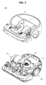
- FIG. 2 is a schematic view showing the appearance of a cleaning robot according to an embodiment of the present disclosure.
- the cleaning robot 100 includes a main body 110 that forms the appearance, a cover 120 that covers an upper portion of the main body 110, the power source unit 130 that supplies a driving power source for driving the main body 110, and a driving unit 140 that moves the main body 110.
- the main body 110 forms the appearance of the cleaning robot 100 and supports various components installed therein.
- the power source unit 130 includes a battery that is electrically connected to the driving unit 140 and each of loads for driving the main body 110 and supplies a driving power source.
- the battery is provided as a rechargeable secondary battery, and charged by receiving supply of electric power from the charge station 300 when the main body 110 completes an operation and then is coupled to the charge station 300.
- the power source unit 130 is charged by receiving supply of a charging current from the charge station 300.
- a caster wheel (not shown) by which a rotation angle of the cleaning robot 100 is changed depending on the state of a bottom surface on which the cleaning robot 100 moves may be installed at a front side of the main body 110.
- the caster wheel is utilized in the posture stability and fall prevention of the cleaning robot 100 to support the cleaning robot 100, and is constituted of a roller or a caster-shaped wheel.
- the driving unit 140 may be respectively provided at both sides of a center portion of the main body 110, and makes movement operations such as forward movement, backward movement, rotation, and the like possible during traveling of the main body 110.
- the driving unit 140 may be rotated in a forward direction or a backward direction according to a command of a processor (180, see FIG. 3 ) to be described later so that the cleaning robot 100 may move forward or backward or rotate.
- the cleaning robot 100 may travel forward or backward by rotating the driving unit 140 in the forward or backward direction.
- the cleaning robot 100 may rotate in a left direction on the basis of the front by rotating the right driving unit 140 in the forward direction while the left driving unit 140 is rotated in the backward direction, and rotate in a right direction on the basis of the front by rotating the left driving unit 140 in the forward direction while the right driving unit 140 is rotated in the backward direction.
- FIG. 3 is a control block diagram showing components of a cleaning robot according to an embodiment of the present disclosure.
- the cleaning robot 100 may include a data acquisition unit 151, a sensor 152, a local map acquisition unit 153, a memory 160, an input unit 171, a display unit 173, a sound output unit 175, and a processor 180 in addition to the components shown in FIG. 2 .
- the data acquisition unit 151 is a component that acquires actual sensor data of a space in which the cleaning robot 100 is currently positioned, and may acquire the actual sensor data by measuring a distance from a current position of the cleaning robot 100 to an object to be measured.
- the cleaning robot 100 may include a sensor (152) for measuring a distance, and acquire actual sensor data of a real environment in which the cleaning robot 100 is positioned by measuring a distance from the sensor(152) to an object to be measured according to scanning of a two-dimensional (2D) sensor or a three-dimensional (3D) sensor installed in the cleaning robot 100.
- the sensor(152) may be a 2D sensor or a 3D sensor.
- the 2D sensor may represent the distance to the object to be measured as (x, y) coordinates based on a reference coordinate system of the sensor
- the 3D sensor may represent the distance to the object to be measured as (x, y, z) coordinates based on the reference coordinate system of the sensor.
- the number of pieces of distance data output from such a 2D or 3D sensor may vary depending on FoV (field of view) and resolution of the sensor.
- the data acquisition unit 151 may change an actual sensor data acquisition method of the cleaning robot 100 depending on the FoV of the 2D or 3D sensor.
- the cleaning robot 100 acquires actual sensor data in a stop state.
- the cleaning robot 100 acquires the actual sensor data while rotating at a predetermined angle in place, or acquires actual sensor data for all directions while rotating at an angle of 360 degrees in place.
- the cleaning robot 100 may acquire the actual sensor data outside the FoV of the sensor.
- the local map acquisition unit 153 may acquire a local map by scanning the vicinity of the current position based on an environmental map stored in advance.
- the local map acquisition unit 153 acquires a local map for the vicinity of the current position of the cleaning robot 100 using virtual sensor data extracted based on the environmental map stored in the memory 160.
- the environmental map in which the cleaning robot is operated may be the same as that in FIG. 4 . It is assumed that an environmental map 500 in which the cleaning robot 100 is operated is given in advance. As shown in FIG. 4 , the environmental map 500 may be a 2D grid map or a 3D grid map.
- the grid map is a map in which the vicinity of the cleaning robot 100 is divided into small grids and a probability that an object exists in each grid is stochastically represented, and also referred to as a probability grid map.
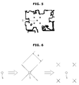
- FIG. 5 is a view showing an extraction position of virtual sensor data in a current position of a cleaning robot according to an embodiment of the present disclosure
- FIG. 6 is a view showing a method of calculating the extraction position of the virtual sensor data of FIG. 5
- FIG. 7 is a view showing an example of a ray casting method according to an embodiment of the present disclosure
- FIG. 8 is a view showing an example of virtual sensor data extracted using the ray casting method of FIG. 7 .
- the local map acquisition unit 153 may acquire a local map through a virtual sensor data extraction method.
- the local map acquisition unit 153 may extract virtual sensor data by performing a ray casting method on all directions while the cleaning robot 100 rotates at an angle of 360 degrees at a virtual sensor data extraction position selected with respect to a current position, thereby acquiring the local map.
- the cleaning robot 100 selects a plurality of virtual sensor data extraction positions X on a map within a predetermined distance with respect to a current position S.
- points at which lines perpendicular to each other with respect to the current position S cross a radius R may be determined as the extraction positions X (see FIG. 6 ).
- the virtual sensor data may be extracted as shown in FIG. 8 by performing a ray casting method on all directions of 360 degrees in each of the virtual sensor data extraction positions X.
- FIG. 8 shows an example of virtual sensor data extracted from a virtual sensor data extraction position X, as shown in FIG. 7 .
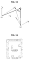
- FIG. 9 is a view showing a position in which a small local map is extracted from a current position of a cleaning robot according to an embodiment of the present disclosure
- FIG. 10 is a view showing an example of a small local map extracted using a small local map extraction position.
- the local map acquisition unit 153 may extract a local map having a preset size from the environmental map 500 with respect to each of a plurality of local map extraction positions selected with respect to the current position of the cleaning robot 100.
- the local map may be classified into a small local map and a large local map having an area larger than the small local map according to the preset size.
- the local map acquisition unit 153 selects a plurality of small local map extraction positions X on a map within a predetermined distance with respect to the current position S of the cleaning robot 100.
- the local map acquisition unit 153 determines a width W and a height H of the small local map based on a maximum detection distance of a sensor mounted in the cleaning robot 100.
- the local map having a size (W x H) determined with respect to each of the small local map extraction positions X is extracted from the environmental map.
- FIG. 10 shows an example of a small local map extracted from the displayed small local map extraction positions X.
- the local map acquisition unit 153 extracts an area wider than the small local map from the environmental map using the current position S of the cleaning robot 100 as a center of large local map extraction.
- the processor 180 may determine coordinates of the current position for the local map by performing matching between the local map and actual sensor data, and calculate a main segment angle of a line segment existing in the local map, thereby determining a traveling direction with respect to the current position.
- the coordinates of the current position may be defined as (x, y, ⁇ ) based on the reference coordinate system ⁇ W ⁇ displayed on the environmental map shown in FIG. 4 .
- x and y denote position coordinates based on the reference coordinate system
- ⁇ denotes a rotation angle.
- the processor 180 is a component that controls overall operations of the cleaning robot 100, and may recognize a relative position of the cleaning robot 100 for the local map by performing matching between the local map and sensor data and determine the traveling direction on the relative position of the cleaning robot 100.
- the processor 180 may determine the main segment angle by classifying a plurality of straight lines existing in the local map according to the angles.
- the processor 180 may cause the cleaning robot 100 to rotate in place based on the traveling direction determined based on the coordinates of the current position.
- the processor 180 may include a position estimation unit 181 for determining current position coordinates of the cleaning robot 100 for the local map, a segment angle calculation unit 183 for calculating a main segment angle of a line segment existing in the local map, and a direction adjustment unit 185 for adjusting the traveling direction of the cleaning robot 100 so that the cleaning robot 100 may rotate according to the main segment angle in a current position.
- FIG. 12 is a control block diagram showing the position estimation unit of FIG. 11 , in detail.
- a position estimation unit 410 may include a corresponding point acquisition unit 411, a relative position calculation unit 413, a similarity calculation unit 415, and a position determination unit 417.
- the corresponding point acquisition unit 411 acquires a plurality of corresponding points through data matching between actual sensor data acquired by the data acquisition unit 151 and a local map acquired by the local map acquisition unit 153.
- FIG. 13 is a view showing an example of actual sensor data acquired by a cleaning robot according to an embodiment of the present disclosure
- FIG. 14 is a view showing an example of virtual sensor data acquired by a cleaning robot according to an embodiment of the present disclosure.
- each sensor data is constituted of a plurality of data points.
- P1 and P2 are in a corresponding point relationship.
- data points constituting the actual sensor data are respectively defined as (x, y) based on a reference coordinate system of the cleaning robot 100.
- Data points constituting the virtual sensor data are defined as (x, y) based on a reference coordinate system ⁇ W ⁇ (see FIG. 4 ) of an environmental map.
- the corresponding point acquisition unit 411 acquires the data points of the actual sensor data which are respectively defined as (x, y) based on the reference coordinate system of the cleaning robot 100 and the data points of the virtual sensor data which are respectively defined as (x, y) based on the reference coordinate system of the environmental map.
- the corresponding point acquisition unit 411 may remove outliers among the acquired plurality of corresponding points.
- the outliers refer to data points which are not commonly included in the actual sensor data and the virtual sensor data.
- the relative position calculation unit 413 calculates a relative position of the actual sensor data for the local map, that is, a coordinate transformation parameter (rotation and translation) using the plurality of corresponding points acquired by the corresponding point acquisition unit 411.
- the relative position calculation unit 413 calculates the remaining plurality of corresponding points (inliers) obtained by removing the outliers, as the relative position of the actual sensor data for the local map.
- the relative position may be obtained by calculating a coordinate transformation parameter (rotation and translation) for fitting the plurality of corresponding points (inliers) included in the actual sensor data into a plurality of corresponding points (inliers) corresponding to each of data points of the local map.
- a coordinate transformation parameter rotation and translation
- Each of the data points of the local map may be defined based on the reference coordinate system of the environmental map, and therefore the coordinate transformation parameter for fitting the actual sensor data indicates the relative position of the cleaning robot 100 for the environmental map.
- a coordinate system ⁇ A ⁇ may be referred to as a reference coordinate system of a local map and a coordinate system ⁇ B ⁇ may be referred to as a reference coordinate system of a sensor.
- R and t denote the coordinate transformation parameter
- R denotes a rotation matrix
- t denotes a translation vector
- R and t are calculated using a least square method.
- the similarity calculation unit 415 calculates similarity between a plurality of local maps and actual sensor data using the relative position of the actual sensor data for the local map calculated by the relative position calculation unit 413.
- the local map shown in FIG. 14 may be considered as a binary image.
- the local map may be expanded as shown in FIG. 16 using a dilation method among digital image processing methods, and similarity is calculated by fitting the actual sensor data into the expanded local map.
- the similarity calculation unit 415 obtains higher similarity along with an increase in the number of data points which are commonly included in the local map and the actual sensor data.
- the position determination unit 417 determines the relative position of the cleaning robot 100 for the local map having the highest similarity using the similarity calculated by the similarity calculation unit 415 as the current position of the cleaning robot 100 for the environmental map, thereby determining current position coordinates.
- a segment angle calculation unit 430 may include a straight line acquisition unit 431 and a main segment angle calculation unit 433.
- the straight line acquisition unit 431 may acquire a plurality of straight lines from the local map acquired by the local map acquisition unit 153. At this time, the straight line acquisition unit 431 may acquire the plurality of straight lines from the local map using Hough transform.
- the plurality of straight lines may be a plurality of point sets constituting a straight line in the local map, or a plurality of point sets constituting the local map itself.
- the straight line acquisition unit 431 acquires the plurality of straight lines for the local map when a vote matrix is calculated by performing Hough transform using a plurality of points constituting the plurality of straight lines extracted from the local map.
- the row and column of the vote matrix respectively correspond to an angle of a line segment and a distance from the origin of the reference coordinate system.
- Each of the plurality of straight lines acquired according to the Hough transform has an angle.
- the main segment angle calculation unit 433 may calculate the main segment angle by classifying the plurality of straight lines according to the angles.
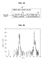
- the main segment angle calculation unit 433 may generate an angle histogram by classifying the plurality of straight lines according to the angles, and determine the main segment angle in consideration of distribution of the angle histogram.
- the main segment angle calculation unit 433 may classify the straight lines acquired by the straight line acquisition unit 431 according to the angles as shown in FIG. 20 , and convert the classified straight lines into the angle histogram.
- main segment angle calculation unit 433 may determine the main segment angle of the local map by removing noise of the angle histogram using a low pass filter.
- the main segment angle calculation unit 433 may perform low pass filtering on the angle histogram, and determine an angle having a maximum vote value as the main segment angle of the local map.
- main segment angle calculation unit 433 may generate the angle histogram by merging the straight lines perpendicular or parallel to each other.
- the main segment angle calculation unit 433 may merge the straight lines having mutually different angles according to a preset condition.
- the main segment angle calculation unit 433 may merge the straight lines perpendicular to each other or the straight lines parallel to each other, thereby improving the reliability of distribution of the main segment angles.
- the main segment angle calculation unit 433 may classify the straight lines parallel to each other (180 degrees) into the same angle, or classify the straight lines perpendicular to each other (90 degrees) into the same angle. In this manner, the main segment angle calculation unit 433 may classify all of the straight lines into a specific range by classifying the straight lines perpendicular or parallel to each other into a single angle.
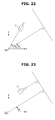
- the main segment angle calculation unit 433 may generate the angle histogram in such a manner that the main segment angle exists in a range of -45° to +45° by merging the straight lines perpendicular or parallel to each other. Specifically, ⁇ L and ⁇ L+90° shown in FIG. 21 are perpendicular to each other. Accordingly, the main segment angle calculation unit 433 may classify ⁇ L+90° together with ⁇ L by moving ⁇ L+90° larger than +45° by 90°.
- the main segment angle calculation unit 433 may calculate an angle in which the largest number of straight line components are distributed as the main segment angle.
- the main segment angle calculation unit 433 may calculate ⁇ L in which the largest number of straight line components exist as the main segment angle. That is, the main segment angle calculation unit 433 may perform low pass filtering on the angle histogram, and then determine the angle having the maximum vote value as the main segment angle.
- the direction adjustment unit 185 may determine the main segment angle in the current position of the cleaning robot 100 as the traveling direction, and rotate the cleaning robot 100 in place in the determined traveling direction.
- the direction adjustment unit 185 may rotate the cleaning robot 100 in place so that the cleaning robot 100 is positioned in the same direction as ⁇ L that is the main segment angle.
- the memory 160 may store the environmental map in which the cleaning robot 100 travels, an operating program for operating the cleaning robot 100 and a traveling pattern, position information of the cleaning robot 100 and obstacle information which are acquired in a traveling process, and the like.
- control data for controlling the operation of the cleaning robot 100 may be stored.
- reference data used during operation control of the cleaning robot 100 may be stored.
- operation data generated while the cleaning robot 100 performs a predetermined operation may be stored.
- the memory 160 may be implemented as a non-volatile memory device such as a ROM (read only memory), a PROM (programmable read only memory), an EPROM (erasable programmed read only memory), or a flash memory, a volatile memory device such as a RAM (random access memory), or a storage medium such as a hard disc, a card type memory (for example, SD or XD memory), or an optical disc.
- a non-volatile memory device such as a ROM (read only memory), a PROM (programmable read only memory), an EPROM (erasable programmed read only memory), or a flash memory
- a volatile memory device such as a RAM (random access memory)
- a storage medium such as a hard disc, a card type memory (for example, SD or XD memory), or an optical disc.
- the memory 160 is not limited thereto, and a variety of storage media which can be considered by a designer may be used.
- the input unit 171 may receive a variety of control information for operating the cleaning robot 100 through a user's operation.
- the display unit 173 is a component for outputting information indicating that the traveling direction of that the cleaning robot 100 is completely adjusted according to the main segment angle, in the form of a message. At this time, the display unit 173 may display the information using icons or LED.
- the display unit 173 is not limited to a notification of the adjustment completion of the traveling direction of the cleaning robot 100, and may output a notification of current position determination even when the current position is determined.
- the display unit 173 when the display unit 173 is an LCD UI (liquid crystal display user interface) in which icon or text display is possible, the display unit 173 may display localization and traveling direction adjustment state of the cleaning robot 100 using icons or texts so that a user may easily confirm the displayed information.
- LCD UI liquid crystal display user interface
- the display unit 173 may display the traveling direction adjustment state of the cleaning robot 100 using lighting or blinking and a duration time difference so that the user may easily confirm the displayed information.
- LED UI light emitting diode user interface
- the display unit 173 may display input information of a user and an operating state of the cleaning robot 100 according to display control signals of the processor 180, and display a variety of information received from the cleaning robot 100, a variety of control commands received from a user through the device, and the like.
- the display unit 173 may display time setting, reservation setting, a time when a control command is directly input, or a speed of the cleaning robot 100, and in the other cases, the display unit 173 may display a current time, reservation information, a remaining battery amount, a movement distance, a movement route, and the like.
- the display unit 173 may include at least one of an LCD (liquid crystal display), a TFT-LCD (thin film transistor-liquid crystal display), an OLED (organic light emitting diode), a flexible display, and a 3D display.
- LCD liquid crystal display
- TFT-LCD thin film transistor-liquid crystal display
- OLED organic light emitting diode
- the sound output unit 175 is a component for outputting information indicating that the traveling direction of the cleaning robot 100 is completely adjusted according to the main segment angle in the form of voice.
- the sound output unit 175 is not limited to a notification of the adjustment completion of the traveling direction of the cleaning robot 100, and may output a notification of current position determination even when the current position is determined.
- the sound output unit 175 may include a speaker that outputs the operating state of the cleaning robot 100 and the adjustment state of the traveling direction of the cleaning robot 100 according to sound control signals of the processor 180 using sound (for example, beep sound).
- the sound output unit 175 may further include a DAC (digital-to-analog converter) that converts a digitalized electrical signal into an analog signal and an amplifier that amplifies an electrical signal turned into an analog signal by the DAC.
- DAC digital-to-analog converter
- FIG. 24 is a flowchart showing a control method of a cleaning robot according to an embodiment of the present disclosure
- FIG. 25 is a flowchart showing a method of estimating a current position of the cleaning robot of FIG. 24
- FIG. 26 is a flowchart showing a method of extracting a segment angle of FIG. 24 .
- the cleaning robot 100 may acquire a local map by scanning the vicinity of a current position.
- the cleaning robot 100 may acquire the local map by scanning the vicinity of the current position based on an environmental map stored in advance in which the cleaning robot 100 travels.
- the environmental map may be a 2D grid map or a 3D grid map.
- the case of above-described operation S110 may include a case in which the cleaning robot 100 is moved to a different position within a predetermined distance by a user during an operation.
- the cleaning robot 100 may extract virtual sensor data by performing a ray casting method on all directions while rotating at 360 degrees in a virtual sensor data extraction position selected with respect to a current position of the cleaning robot 100 and thereby acquire the local map, or extract the local map (for example, a small local map or a large local map) having a preset size with respect to each of a plurality of local map extraction positions selected with respect to the current position of the cleaning robot 100.
- the local map for example, a small local map or a large local map
- an area wider than the small local map may be extracted from the environmental map using a position to which the cleaning robot 100 is moved as a center of large local map extraction.
- the cleaning robot 100 may acquire actual sensor data by measuring a distance from the current position to an object to be measured, and determine current position coordinates for the local map by performing matching between the local map and the actual sensor data.
- the cleaning robot 100 may acquire the actual sensor data by measuring the distance from the current position to the object to be measured.
- the cleaning robot 100 includes a sensor (not shown) for measuring a distance, and may acquire actual sensor data of a real environment in which the cleaning robot 100 is positioned by measuring a distance from the sensor to the object to be measured according to scanning of a 2D sensor or a 3D sensor installed in the cleaning robot 100.
- the cleaning robot 100 may acquire data outside FoV of the sensor while rotating at a predetermined angle in place, or acquire actual sensor data for all directions while rotating at an angle of 360 degrees in place.
- the cleaning robot 100 may acquire a plurality of corresponding points through data matching between the actual sensor data and the local map.
- the cleaning robot 100 may acquire corresponding points which correspond to each other between data points of actual sensor data defined as (x, y) based on a reference coordinate system and a plurality of data points of virtual sensor data defined as (x, y) based on a reference coordinate system of the environmental map.
- the cleaning robot 100 may remove outliers among the plurality of corresponding points.
- the cleaning robot 100 may calculate a relative position of the actual sensor data for the local map using the acquired plurality of corresponding points.
- the cleaning robot 100 may calculate the relative position of the actual sensor data for the local map, that is, a coordinate transformation parameter (rotation and translation) using the plurality of corresponding points.
- the cleaning robot 100 may calculate similarity between a plurality of local maps and the actual sensor data.
- the cleaning robot 100 may determine the relative position of the cleaning robot for the local map having the highest similarity as the current position of the cleaning robot for the environmental map.
- the current position of the cleaning robot may be provided in the form of current position coordinates.
- operation S143 when the position of the cleaning robot 100 is determined, information indicating that the position of the cleaning robot 100 is completely recognized is notified to a user.
- the display unit 173 may display the localization through icons or lighting and blinking of LED or the sound output unit 175 may output sound (for example, beep sound), so that a user may easily confirm the notification.
- operation S143 may be omitted according to needs of an operator.
- the cleaning robot 100 may determine a traveling direction by calculating a main segment angle of a line segment existing in the local map.
- the cleaning robot 100 may acquire a plurality of straight lines from the local map.
- the cleaning robot 100 may classify the plurality of straight lines according to the angles and calculate the main segment angle.
- Operation S155 may include an operation of classifying the plurality of straight lines according to the angles and generating an angle histogram and an operation of determining the main segment angle in consideration of distribution of the angle histogram.
- operation S155 may further include an operation of merging the straight lines perpendicular or parallel to each other in the angle histogram.
- the cleaning robot 100 may adjust the traveling direction according to the calculated main segment angle.
- the cleaning robot 100 may output information indicating that the traveling direction of the cleaning robot is adjusted according to the main segment angle in the form of a message or sound.
- FIG. 27 is a control block diagram showing components of a localization apparatus for a cleaning robot according to an embodiment of the present disclosure.
- a localization apparatus 600 for the cleaning robot includes a data acquisition unit 610, a memory 620, a processor 630, a display unit 640, and a sound output unit 650.
- the data acquisition unit 610 acquires actual sensor data in which the cleaning robot 100 is currently positioned, and measures a distance to an object to be measured according to scanning of a 2D sensor or a 3D sensor installed in the cleaning robot 100 and thereby acquires distance data of a real environment in which the cleaning robot 100 is positioned.
- an actual sensor data acquisition method by the cleaning robot 100 may vary depending on FoV of the 2D sensor or the 3D sensor.
- the cleaning robot 100 acquires actual sensor data in a stop state.
- the cleaning robot 100 acquires data outside the FoV of the sensor while rotating at a predetermined angle in place or acquires actual sensor data for all directions while rotating at an angle of 360 degrees in place.
- the memory 620 stores an environmental map in which the cleaning robot 100 is operated, an operating program for operating the cleaning robot 100 and a traveling pattern, position information of the cleaning robot 100 and obstacle information which are acquired in a traveling process, and the like.
- control data for controlling the operation of the cleaning robot 100 may be stored.
- reference data used during operation control of the cleaning robot 100 may be stored.
- operation data generated while the cleaning robot 100 performs a predetermined operation may be stored.
- the processor 630 is a component that controls overall operations of the cleaning robot 100, and may recognize a relative position of the cleaning robot 100 for a local map by performing matching between the local map and sensor data.
- the processor 630 further includes a local map acquisition unit 631, a corresponding point acquisition unit 632, a relative position calculation unit 633, a similarity calculation unit 634, and a position determination unit 635.
- the local map acquisition unit 631 acquires a local map for the vicinity of a position to which the cleaning robot 100 is moved using virtual sensor data extracted based on an environmental map stored in the memory 620.
- the corresponding point acquisition unit 632 acquires corresponding points through data matching between the actual sensor data acquired by the data acquisition unit 610 and the local map acquired by the local map acquisition unit 631.
- the relative position calculation unit 633 calculates a relative position of the actual sensor data for the local map, that is, a coordinate transformation parameter (rotation and translation) using the corresponding points acquired by the corresponding point acquisition unit 632.
- the similarity calculation unit 634 calculates similarity between a plurality of local maps and the actual sensor data using the relative position of the actual sensor data for the local map calculated by the relative position calculation unit 633.
- the local map may be considered as a binary image.
- the local map may be expanded using a dilation method among digital image processing methods, and the similarity is calculated by fitting the actual sensor data into the expanded local map. That is, the actual sensor data shown in FIG. 13 is fitted into the expanded local map shown in FIG. 16 .
- the number of overlapped data points between the expanded local maps among data points of the actual sensor data may be used as the similarity.
- the position determination unit 635 determines the relative position of the cleaning robot 100 for the local map having the highest similarity using the similarity calculated by the similarity calculation unit 634 as the position of the cleaning robot 100 for the environmental map.
- the display unit 640 displays information for notifying that the position of the cleaning robot 100 is completely recognized, using icons or LED.
- the sound output unit 650 may include a speaker that outputs the operating state and localization state of the cleaning robot 100 according to sound control signals of the processor 630 using sound (for example, beep sound).
- the cleaning robot 100 operated in a complex environment such as general home is forcibly moved by a user, as necessary.
- a user should lift and move the cleaning robot 100 to a different position.
- the cleaning robot 100 should quickly and accurately recognize a new position to which the cleaning robot is moved.
- the cleaning robot 100 should unnecessarily move a predetermined distance in an arbitrary direction in order to converge particles into one position so that a movement distance is increased, which is inefficient.
- a larger number of particles are required as much as possible in order to increase a success rate of the localization, so that a calculation time for the localization is increased.
- a current position of the cleaning robot may be quickly and accurately recognized by scanning the vicinity of the position to which the cleaning robot is moved while the cleaning robot rotates at a predetermined angle or 360 degrees in place without unnecessary movement, thereby reducing a time required for the localization.
- information indicating that the localization is completed may be notified through a display or sound, thereby increasing user's reliability for a product.
- the traveling direction of the cleaning robot may be determined using the environmental map in which the cleaning robot performs an operation and the position of the cleaning robot on the environmental map, and therefore a more accurate traveling direction may be determined so that a cleaning omission area is not generated, thereby improving reliability for a cleaning operation.
Landscapes
- Engineering & Computer Science (AREA)
- Physics & Mathematics (AREA)
- Radar, Positioning & Navigation (AREA)
- Automation & Control Theory (AREA)
- General Physics & Mathematics (AREA)
- Remote Sensing (AREA)
- Aviation & Aerospace Engineering (AREA)
- Mechanical Engineering (AREA)
- Electromagnetism (AREA)
- Optics & Photonics (AREA)
- Robotics (AREA)
- Software Systems (AREA)
- Mathematical Physics (AREA)
- Fuzzy Systems (AREA)
- Evolutionary Computation (AREA)
- Artificial Intelligence (AREA)
- Control Of Position, Course, Altitude, Or Attitude Of Moving Bodies (AREA)
Applications Claiming Priority (2)
| Application Number | Priority Date | Filing Date | Title |
|---|---|---|---|
| KR1020150132274A KR102386361B1 (ko) | 2015-09-18 | 2015-09-18 | 이동 로봇의 위치 인식 장치 및 그 방법 |
| KR1020150148434A KR102471487B1 (ko) | 2015-10-26 | 2015-10-26 | 청소 로봇 및 그 제어방법 |
Publications (2)
| Publication Number | Publication Date |
|---|---|
| EP3144765A1 true EP3144765A1 (de) | 2017-03-22 |
| EP3144765B1 EP3144765B1 (de) | 2020-01-08 |
Family
ID=56296577
Family Applications (1)
| Application Number | Title | Priority Date | Filing Date |
|---|---|---|---|
| EP16176784.3A Active EP3144765B1 (de) | 2015-09-18 | 2016-06-29 | Vorrichtung zur ortung eines reinigungsroboters, reinigungsroboter und steuerungsverfahren für einen reinigungsroboter |
Country Status (3)
| Country | Link |
|---|---|
| US (1) | US10663972B2 (de) |
| EP (1) | EP3144765B1 (de) |
| CN (1) | CN106541407B (de) |
Cited By (6)
| Publication number | Priority date | Publication date | Assignee | Title |
|---|---|---|---|---|
| CN110705385A (zh) * | 2019-09-12 | 2020-01-17 | 深兰科技(上海)有限公司 | 一种障碍物角度的检测方法、装置、设备及介质 |
| CN110998473A (zh) * | 2017-09-04 | 2020-04-10 | 日本电产株式会社 | 位置推断系统和具有该位置推断系统的移动体 |
| EP3686703A4 (de) * | 2017-08-02 | 2020-12-23 | Ankobot (Shenzhen) Smart Technologies Co., Ltd. | Steuerungsverfahren, -vorrichtung und -system für roboter und anwendbarer roboter |
| CN112437064A (zh) * | 2020-11-12 | 2021-03-02 | 深圳市银星智能科技股份有限公司 | 数据传输方法、数据读取方法、装置、设备及存储介质 |
| CN112867977A (zh) * | 2021-01-13 | 2021-05-28 | 华为技术有限公司 | 一种定位方法、装置和车辆 |
| CN114365983A (zh) * | 2022-01-24 | 2022-04-19 | 北京卡普拉科技有限公司 | 清洁方法、装置、电子设备、存储介质及机器人设备 |
Families Citing this family (23)
| Publication number | Priority date | Publication date | Assignee | Title |
|---|---|---|---|---|
| EP2952993B1 (de) * | 2014-06-05 | 2018-04-25 | Softbank Robotics Europe | Verfahren zur Herstellung einer Karte der Wahrscheinlichkeit des Nichtvorhandenseins und Vorhandenseins von Hindernissen für einen autonomen Roboter |
| US9519289B2 (en) | 2014-11-26 | 2016-12-13 | Irobot Corporation | Systems and methods for performing simultaneous localization and mapping using machine vision systems |
| US9751210B2 (en) * | 2014-11-26 | 2017-09-05 | Irobot Corporation | Systems and methods for performing occlusion detection |
| US9943959B2 (en) * | 2016-04-25 | 2018-04-17 | Disney Enterprises, Inc. | Map localizing with partially obstructed ranging devices for autonomous robots and vehicles |
| CN110720025B (zh) * | 2017-06-16 | 2023-11-10 | 宝马股份公司 | 移动物体的地图的选择方法、装置、系统和车辆/机器人 |
| JP7087290B2 (ja) * | 2017-07-05 | 2022-06-21 | カシオ計算機株式会社 | 自律移動装置、自律移動方法及びプログラム |
| CN107976194B (zh) * | 2017-11-24 | 2021-12-21 | 北京奇虎科技有限公司 | 环境地图的调整方法及装置 |
| CN107932481A (zh) * | 2017-12-04 | 2018-04-20 | 湖南瑞森可机器人科技有限公司 | 一种复合机器人及其控制方法 |
| WO2019183804A1 (zh) * | 2018-03-27 | 2019-10-03 | 尤中乾 | 一种机器人规避控制方法及相关装置 |
| CN108507578B (zh) * | 2018-04-03 | 2021-04-30 | 珠海市一微半导体有限公司 | 一种机器人的导航方法 |
| WO2019209877A1 (en) * | 2018-04-23 | 2019-10-31 | Sharkninja Operating Llc | Techniques for bounding cleaning operations of a robotic surface cleaning device within a region of interest |
| CN108606728B (zh) * | 2018-05-08 | 2020-12-25 | 平安科技(深圳)有限公司 | 一种扫地机器人控制方法、设备、扫地机器人及存储介质 |
| CN110856631B (zh) * | 2018-08-24 | 2021-09-14 | 东芝生活电器株式会社 | 电动吸尘器以及电动吸尘系统 |
| CN109900272B (zh) * | 2019-02-25 | 2021-07-13 | 浙江大学 | 视觉定位与建图方法、装置及电子设备 |
| CN112205937B (zh) * | 2019-07-12 | 2022-04-05 | 北京石头世纪科技股份有限公司 | 一种自动清洁设备控制方法、装置、设备和介质 |
| CN110909585B (zh) * | 2019-08-15 | 2022-09-06 | 纳恩博(常州)科技有限公司 | 一种路线确定方法、可行进设备、和存储介质 |
| CN112747734B (zh) * | 2019-10-31 | 2024-04-30 | 深圳拓邦股份有限公司 | 环境地图方向调整方法、系统及装置 |
| WO2021125510A1 (en) | 2019-12-20 | 2021-06-24 | Samsung Electronics Co., Ltd. | Method and device for navigating in dynamic environment |
| KR20210096523A (ko) * | 2020-01-28 | 2021-08-05 | 엘지전자 주식회사 | 로봇의 위치 인식 |
| CN113449054B (zh) * | 2020-03-27 | 2023-08-04 | 杭州海康机器人股份有限公司 | 一种地图切换的方法和移动机器人 |
| CN113729572B (zh) * | 2020-05-29 | 2022-12-06 | 宝时得科技(中国)有限公司 | 清洁机器人及其控制方法 |
| CN116033330A (zh) * | 2021-10-25 | 2023-04-28 | 华为技术有限公司 | 一种基于人体感知的自动控制方法、第一电子设备及系统 |
| CN113878582B (zh) * | 2021-10-29 | 2023-05-12 | 上海擎朗智能科技有限公司 | 机器人行驶控制方法、装置、机器人和存储介质 |
Citations (3)
| Publication number | Priority date | Publication date | Assignee | Title |
|---|---|---|---|---|
| US20080046125A1 (en) * | 2006-08-18 | 2008-02-21 | Samsung Electronics Co., Ltd. | Method of dividing coverage area for robot and device thereof |
| US8060254B2 (en) * | 2006-06-20 | 2011-11-15 | Samsung Electronics Co., Ltd. | Method, apparatus, and medium for building grid map in mobile robot and method, apparatus, and medium for cell decomposition that uses grid map |
| US20150012209A1 (en) * | 2013-07-03 | 2015-01-08 | Samsung Electronics Co., Ltd. | Position recognition methods of autonomous mobile robots |
Family Cites Families (12)
| Publication number | Priority date | Publication date | Assignee | Title |
|---|---|---|---|---|
| KR950005403B1 (ko) | 1993-04-28 | 1995-05-24 | 주식회사금성사 | 신경회로망을 이용한 자동 주행 청소기의 주행 제어방법 |
| JP4243594B2 (ja) | 2005-01-31 | 2009-03-25 | パナソニック電工株式会社 | 清掃ロボット |
| KR101457148B1 (ko) * | 2008-05-21 | 2014-10-31 | 삼성전자 주식회사 | 로봇의 위치 추정 장치 및 그 방법 |
| KR20110085500A (ko) | 2010-01-20 | 2011-07-27 | 엘지전자 주식회사 | 로봇 청소기 및 이의 제어 방법 |
| KR101202108B1 (ko) | 2010-06-03 | 2012-11-15 | 고려대학교 산학협력단 | 이동 로봇의 위치 추정 방법 |
| KR101341204B1 (ko) | 2012-02-29 | 2013-12-12 | 부산대학교 산학협력단 | 레이저 스캐너 및 구조물을 이용한 모바일 로봇의 위치추정장치 및 방법 |
| KR101406175B1 (ko) | 2012-10-09 | 2014-06-13 | 조선대학교산학협력단 | 이동로봇의 위치추정과 지도 작성 장치 및 방법 |
| US9233472B2 (en) * | 2013-01-18 | 2016-01-12 | Irobot Corporation | Mobile robot providing environmental mapping for household environmental control |
| JP6233706B2 (ja) | 2013-04-02 | 2017-11-22 | パナソニックIpマネジメント株式会社 | 自律移動装置及び自律移動装置の自己位置推定方法 |
| KR102093177B1 (ko) | 2013-10-31 | 2020-03-25 | 엘지전자 주식회사 | 이동 로봇 및 그 동작방법 |
| KR20150136872A (ko) | 2014-05-28 | 2015-12-08 | 삼성전자주식회사 | 청소 로봇 및 그 제어 방법 |
| CN104848848A (zh) | 2015-03-30 | 2015-08-19 | 北京云迹科技有限公司 | 基于无线基站和激光传感器的机器人绘制地图和定位的方法及系统 |
-
2016
- 2016-06-29 EP EP16176784.3A patent/EP3144765B1/de active Active
- 2016-07-06 US US15/203,079 patent/US10663972B2/en active Active
- 2016-08-30 CN CN201610773063.XA patent/CN106541407B/zh not_active Expired - Fee Related
Patent Citations (3)
| Publication number | Priority date | Publication date | Assignee | Title |
|---|---|---|---|---|
| US8060254B2 (en) * | 2006-06-20 | 2011-11-15 | Samsung Electronics Co., Ltd. | Method, apparatus, and medium for building grid map in mobile robot and method, apparatus, and medium for cell decomposition that uses grid map |
| US20080046125A1 (en) * | 2006-08-18 | 2008-02-21 | Samsung Electronics Co., Ltd. | Method of dividing coverage area for robot and device thereof |
| US20150012209A1 (en) * | 2013-07-03 | 2015-01-08 | Samsung Electronics Co., Ltd. | Position recognition methods of autonomous mobile robots |
Cited By (7)
| Publication number | Priority date | Publication date | Assignee | Title |
|---|---|---|---|---|
| EP3686703A4 (de) * | 2017-08-02 | 2020-12-23 | Ankobot (Shenzhen) Smart Technologies Co., Ltd. | Steuerungsverfahren, -vorrichtung und -system für roboter und anwendbarer roboter |
| CN110998473A (zh) * | 2017-09-04 | 2020-04-10 | 日本电产株式会社 | 位置推断系统和具有该位置推断系统的移动体 |
| CN110705385A (zh) * | 2019-09-12 | 2020-01-17 | 深兰科技(上海)有限公司 | 一种障碍物角度的检测方法、装置、设备及介质 |
| CN110705385B (zh) * | 2019-09-12 | 2022-05-03 | 深兰科技(上海)有限公司 | 一种障碍物角度的检测方法、装置、设备及介质 |
| CN112437064A (zh) * | 2020-11-12 | 2021-03-02 | 深圳市银星智能科技股份有限公司 | 数据传输方法、数据读取方法、装置、设备及存储介质 |
| CN112867977A (zh) * | 2021-01-13 | 2021-05-28 | 华为技术有限公司 | 一种定位方法、装置和车辆 |
| CN114365983A (zh) * | 2022-01-24 | 2022-04-19 | 北京卡普拉科技有限公司 | 清洁方法、装置、电子设备、存储介质及机器人设备 |
Also Published As
| Publication number | Publication date |
|---|---|
| US10663972B2 (en) | 2020-05-26 |
| CN106541407B (zh) | 2020-05-19 |
| US20170083023A1 (en) | 2017-03-23 |
| EP3144765B1 (de) | 2020-01-08 |
| CN106541407A (zh) | 2017-03-29 |
Similar Documents
| Publication | Publication Date | Title |
|---|---|---|
| EP3144765B1 (de) | Vorrichtung zur ortung eines reinigungsroboters, reinigungsroboter und steuerungsverfahren für einen reinigungsroboter | |
| CN108290294B (zh) | 移动机器人及其控制方法 | |
| CN114521836B (zh) | 一种自动清洁设备 | |
| US20230021778A1 (en) | Systems and methods for training a robot to autonomously travel a route | |
| KR102457222B1 (ko) | 이동 로봇 및 그 제어 방법 | |
| TWI687784B (zh) | 移動式機器人及其控制方法 | |
| CN110037621B (zh) | 移动装置、清洁机器人及其控制方法 | |
| EP3027101B1 (de) | Selbstreinigendes system, reinigungsroboter und verfahren zur steuerung des reinigungsroboters | |
| EP3863813B1 (de) | Reinigungsroboter und verfahren zur ausführung von aufgaben damit | |
| US8265425B2 (en) | Rectangular table detection using hybrid RGB and depth camera sensors | |
| US11537135B2 (en) | Moving robot and controlling method for the moving robot | |
| KR102386361B1 (ko) | 이동 로봇의 위치 인식 장치 및 그 방법 | |
| KR102302199B1 (ko) | 이동 장치 및 이동 장치의 객체 감지 방법 | |
| US11627853B2 (en) | Robotic cleaner and control method therefor | |
| CN109254580A (zh) | 用于自动行走式的服务设备的运行方法 | |
| KR102471487B1 (ko) | 청소 로봇 및 그 제어방법 | |
| EP3240137B1 (de) | Automatisches stromversorgungssystem, automatische stromversorgungsvorrichtung und autonomes bewegungssystem | |
| CN112405549B (zh) | 一种机器人的定位方法和装置 | |
| EP4310623A1 (de) | Systeme und verfahren für roboternavigation, -lehr und -kartierung | |
| KR20230029427A (ko) | 로봇 청소기 및 그의 위치 식별 방법 | |
| KR20210104530A (ko) | 로봇 및 이의 제어 방법 |
Legal Events
| Date | Code | Title | Description |
|---|---|---|---|
| PUAI | Public reference made under article 153(3) epc to a published international application that has entered the european phase |
Free format text: ORIGINAL CODE: 0009012 |
|
| STAA | Information on the status of an ep patent application or granted ep patent |
Free format text: STATUS: REQUEST FOR EXAMINATION WAS MADE |
|
| 17P | Request for examination filed |
Effective date: 20160629 |
|
| AK | Designated contracting states |
Kind code of ref document: A1 Designated state(s): AL AT BE BG CH CY CZ DE DK EE ES FI FR GB GR HR HU IE IS IT LI LT LU LV MC MK MT NL NO PL PT RO RS SE SI SK SM TR |
|
| AX | Request for extension of the european patent |
Extension state: BA ME |
|
| GRAP | Despatch of communication of intention to grant a patent |
Free format text: ORIGINAL CODE: EPIDOSNIGR1 |
|
| STAA | Information on the status of an ep patent application or granted ep patent |
Free format text: STATUS: GRANT OF PATENT IS INTENDED |
|
| INTG | Intention to grant announced |
Effective date: 20190812 |
|
| GRAS | Grant fee paid |
Free format text: ORIGINAL CODE: EPIDOSNIGR3 |
|
| GRAA | (expected) grant |
Free format text: ORIGINAL CODE: 0009210 |
|
| STAA | Information on the status of an ep patent application or granted ep patent |
Free format text: STATUS: THE PATENT HAS BEEN GRANTED |
|
| AK | Designated contracting states |
Kind code of ref document: B1 Designated state(s): AL AT BE BG CH CY CZ DE DK EE ES FI FR GB GR HR HU IE IS IT LI LT LU LV MC MK MT NL NO PL PT RO RS SE SI SK SM TR |
|
| REG | Reference to a national code |
Ref country code: GB Ref legal event code: FG4D |
|
| REG | Reference to a national code |
Ref country code: CH Ref legal event code: EP |
|
| REG | Reference to a national code |
Ref country code: DE Ref legal event code: R096 Ref document number: 602016027679 Country of ref document: DE |
|
| REG | Reference to a national code |
Ref country code: IE Ref legal event code: FG4D |
|
| REG | Reference to a national code |
Ref country code: AT Ref legal event code: REF Ref document number: 1223482 Country of ref document: AT Kind code of ref document: T Effective date: 20200215 |
|
| REG | Reference to a national code |
Ref country code: NL Ref legal event code: FP |
|
| REG | Reference to a national code |
Ref country code: LT Ref legal event code: MG4D |
|
| PG25 | Lapsed in a contracting state [announced via postgrant information from national office to epo] |
Ref country code: FI Free format text: LAPSE BECAUSE OF FAILURE TO SUBMIT A TRANSLATION OF THE DESCRIPTION OR TO PAY THE FEE WITHIN THE PRESCRIBED TIME-LIMIT Effective date: 20200108 Ref country code: PT Free format text: LAPSE BECAUSE OF FAILURE TO SUBMIT A TRANSLATION OF THE DESCRIPTION OR TO PAY THE FEE WITHIN THE PRESCRIBED TIME-LIMIT Effective date: 20200531 Ref country code: RS Free format text: LAPSE BECAUSE OF FAILURE TO SUBMIT A TRANSLATION OF THE DESCRIPTION OR TO PAY THE FEE WITHIN THE PRESCRIBED TIME-LIMIT Effective date: 20200108 Ref country code: LT Free format text: LAPSE BECAUSE OF FAILURE TO SUBMIT A TRANSLATION OF THE DESCRIPTION OR TO PAY THE FEE WITHIN THE PRESCRIBED TIME-LIMIT Effective date: 20200108 Ref country code: NO Free format text: LAPSE BECAUSE OF FAILURE TO SUBMIT A TRANSLATION OF THE DESCRIPTION OR TO PAY THE FEE WITHIN THE PRESCRIBED TIME-LIMIT Effective date: 20200408 |
|
| PG25 | Lapsed in a contracting state [announced via postgrant information from national office to epo] |
Ref country code: IS Free format text: LAPSE BECAUSE OF FAILURE TO SUBMIT A TRANSLATION OF THE DESCRIPTION OR TO PAY THE FEE WITHIN THE PRESCRIBED TIME-LIMIT Effective date: 20200508 Ref country code: BG Free format text: LAPSE BECAUSE OF FAILURE TO SUBMIT A TRANSLATION OF THE DESCRIPTION OR TO PAY THE FEE WITHIN THE PRESCRIBED TIME-LIMIT Effective date: 20200408 Ref country code: SE Free format text: LAPSE BECAUSE OF FAILURE TO SUBMIT A TRANSLATION OF THE DESCRIPTION OR TO PAY THE FEE WITHIN THE PRESCRIBED TIME-LIMIT Effective date: 20200108 Ref country code: LV Free format text: LAPSE BECAUSE OF FAILURE TO SUBMIT A TRANSLATION OF THE DESCRIPTION OR TO PAY THE FEE WITHIN THE PRESCRIBED TIME-LIMIT Effective date: 20200108 Ref country code: GR Free format text: LAPSE BECAUSE OF FAILURE TO SUBMIT A TRANSLATION OF THE DESCRIPTION OR TO PAY THE FEE WITHIN THE PRESCRIBED TIME-LIMIT Effective date: 20200409 Ref country code: HR Free format text: LAPSE BECAUSE OF FAILURE TO SUBMIT A TRANSLATION OF THE DESCRIPTION OR TO PAY THE FEE WITHIN THE PRESCRIBED TIME-LIMIT Effective date: 20200108 |
|
| REG | Reference to a national code |
Ref country code: DE Ref legal event code: R097 Ref document number: 602016027679 Country of ref document: DE |
|
| PG25 | Lapsed in a contracting state [announced via postgrant information from national office to epo] |
Ref country code: ES Free format text: LAPSE BECAUSE OF FAILURE TO SUBMIT A TRANSLATION OF THE DESCRIPTION OR TO PAY THE FEE WITHIN THE PRESCRIBED TIME-LIMIT Effective date: 20200108 Ref country code: DK Free format text: LAPSE BECAUSE OF FAILURE TO SUBMIT A TRANSLATION OF THE DESCRIPTION OR TO PAY THE FEE WITHIN THE PRESCRIBED TIME-LIMIT Effective date: 20200108 Ref country code: SK Free format text: LAPSE BECAUSE OF FAILURE TO SUBMIT A TRANSLATION OF THE DESCRIPTION OR TO PAY THE FEE WITHIN THE PRESCRIBED TIME-LIMIT Effective date: 20200108 Ref country code: SM Free format text: LAPSE BECAUSE OF FAILURE TO SUBMIT A TRANSLATION OF THE DESCRIPTION OR TO PAY THE FEE WITHIN THE PRESCRIBED TIME-LIMIT Effective date: 20200108 Ref country code: EE Free format text: LAPSE BECAUSE OF FAILURE TO SUBMIT A TRANSLATION OF THE DESCRIPTION OR TO PAY THE FEE WITHIN THE PRESCRIBED TIME-LIMIT Effective date: 20200108 Ref country code: RO Free format text: LAPSE BECAUSE OF FAILURE TO SUBMIT A TRANSLATION OF THE DESCRIPTION OR TO PAY THE FEE WITHIN THE PRESCRIBED TIME-LIMIT Effective date: 20200108 Ref country code: CZ Free format text: LAPSE BECAUSE OF FAILURE TO SUBMIT A TRANSLATION OF THE DESCRIPTION OR TO PAY THE FEE WITHIN THE PRESCRIBED TIME-LIMIT Effective date: 20200108 |
|
| PLBE | No opposition filed within time limit |
Free format text: ORIGINAL CODE: 0009261 |
|
| STAA | Information on the status of an ep patent application or granted ep patent |
Free format text: STATUS: NO OPPOSITION FILED WITHIN TIME LIMIT |
|
| REG | Reference to a national code |
Ref country code: AT Ref legal event code: MK05 Ref document number: 1223482 Country of ref document: AT Kind code of ref document: T Effective date: 20200108 |
|
| 26N | No opposition filed |
Effective date: 20201009 |
|
| PG25 | Lapsed in a contracting state [announced via postgrant information from national office to epo] |
Ref country code: IT Free format text: LAPSE BECAUSE OF FAILURE TO SUBMIT A TRANSLATION OF THE DESCRIPTION OR TO PAY THE FEE WITHIN THE PRESCRIBED TIME-LIMIT Effective date: 20200108 Ref country code: AT Free format text: LAPSE BECAUSE OF FAILURE TO SUBMIT A TRANSLATION OF THE DESCRIPTION OR TO PAY THE FEE WITHIN THE PRESCRIBED TIME-LIMIT Effective date: 20200108 Ref country code: MC Free format text: LAPSE BECAUSE OF FAILURE TO SUBMIT A TRANSLATION OF THE DESCRIPTION OR TO PAY THE FEE WITHIN THE PRESCRIBED TIME-LIMIT Effective date: 20200108 |
|
| REG | Reference to a national code |
Ref country code: CH Ref legal event code: PL |
|
| PG25 | Lapsed in a contracting state [announced via postgrant information from national office to epo] |
Ref country code: SI Free format text: LAPSE BECAUSE OF FAILURE TO SUBMIT A TRANSLATION OF THE DESCRIPTION OR TO PAY THE FEE WITHIN THE PRESCRIBED TIME-LIMIT Effective date: 20200108 Ref country code: PL Free format text: LAPSE BECAUSE OF FAILURE TO SUBMIT A TRANSLATION OF THE DESCRIPTION OR TO PAY THE FEE WITHIN THE PRESCRIBED TIME-LIMIT Effective date: 20200108 |
|
| PG25 | Lapsed in a contracting state [announced via postgrant information from national office to epo] |
Ref country code: LU Free format text: LAPSE BECAUSE OF NON-PAYMENT OF DUE FEES Effective date: 20200629 |
|
| REG | Reference to a national code |
Ref country code: BE Ref legal event code: MM Effective date: 20200630 |
|
| PG25 | Lapsed in a contracting state [announced via postgrant information from national office to epo] |
Ref country code: CH Free format text: LAPSE BECAUSE OF NON-PAYMENT OF DUE FEES Effective date: 20200630 Ref country code: LI Free format text: LAPSE BECAUSE OF NON-PAYMENT OF DUE FEES Effective date: 20200630 Ref country code: FR Free format text: LAPSE BECAUSE OF NON-PAYMENT OF DUE FEES Effective date: 20200630 Ref country code: IE Free format text: LAPSE BECAUSE OF NON-PAYMENT OF DUE FEES Effective date: 20200629 |
|
| PG25 | Lapsed in a contracting state [announced via postgrant information from national office to epo] |
Ref country code: BE Free format text: LAPSE BECAUSE OF NON-PAYMENT OF DUE FEES Effective date: 20200630 |
|
| PGFP | Annual fee paid to national office [announced via postgrant information from national office to epo] |
Ref country code: NL Payment date: 20210521 Year of fee payment: 6 |
|
| PGFP | Annual fee paid to national office [announced via postgrant information from national office to epo] |
Ref country code: GB Payment date: 20210524 Year of fee payment: 6 |
|
| PG25 | Lapsed in a contracting state [announced via postgrant information from national office to epo] |
Ref country code: TR Free format text: LAPSE BECAUSE OF FAILURE TO SUBMIT A TRANSLATION OF THE DESCRIPTION OR TO PAY THE FEE WITHIN THE PRESCRIBED TIME-LIMIT Effective date: 20200108 Ref country code: MT Free format text: LAPSE BECAUSE OF FAILURE TO SUBMIT A TRANSLATION OF THE DESCRIPTION OR TO PAY THE FEE WITHIN THE PRESCRIBED TIME-LIMIT Effective date: 20200108 Ref country code: CY Free format text: LAPSE BECAUSE OF FAILURE TO SUBMIT A TRANSLATION OF THE DESCRIPTION OR TO PAY THE FEE WITHIN THE PRESCRIBED TIME-LIMIT Effective date: 20200108 |
|
| PG25 | Lapsed in a contracting state [announced via postgrant information from national office to epo] |
Ref country code: MK Free format text: LAPSE BECAUSE OF FAILURE TO SUBMIT A TRANSLATION OF THE DESCRIPTION OR TO PAY THE FEE WITHIN THE PRESCRIBED TIME-LIMIT Effective date: 20200108 Ref country code: AL Free format text: LAPSE BECAUSE OF FAILURE TO SUBMIT A TRANSLATION OF THE DESCRIPTION OR TO PAY THE FEE WITHIN THE PRESCRIBED TIME-LIMIT Effective date: 20200108 |
|
| REG | Reference to a national code |
Ref country code: NL Ref legal event code: MM Effective date: 20220701 |
|
| GBPC | Gb: european patent ceased through non-payment of renewal fee |
Effective date: 20220629 |
|
| PG25 | Lapsed in a contracting state [announced via postgrant information from national office to epo] |
Ref country code: NL Free format text: LAPSE BECAUSE OF NON-PAYMENT OF DUE FEES Effective date: 20220701 |
|
| PG25 | Lapsed in a contracting state [announced via postgrant information from national office to epo] |
Ref country code: GB Free format text: LAPSE BECAUSE OF NON-PAYMENT OF DUE FEES Effective date: 20220629 |
|
| PGFP | Annual fee paid to national office [announced via postgrant information from national office to epo] |
Ref country code: DE Payment date: 20230522 Year of fee payment: 8 |
|
| REG | Reference to a national code |
Ref country code: DE Ref legal event code: R079 Ref document number: 602016027679 Country of ref document: DE Free format text: PREVIOUS MAIN CLASS: G05D0001020000 Ipc: G05D0001430000 |