EP3144591A1 - Kühlkörper - Google Patents
Kühlkörper Download PDFInfo
- Publication number
- EP3144591A1 EP3144591A1 EP16189209.6A EP16189209A EP3144591A1 EP 3144591 A1 EP3144591 A1 EP 3144591A1 EP 16189209 A EP16189209 A EP 16189209A EP 3144591 A1 EP3144591 A1 EP 3144591A1
- Authority
- EP
- European Patent Office
- Prior art keywords
- flaps
- heat sink
- axis
- central body
- adjacent
- Prior art date
- Legal status (The legal status is an assumption and is not a legal conclusion. Google has not performed a legal analysis and makes no representation as to the accuracy of the status listed.)
- Granted
Links
Images


Classifications
-
- F—MECHANICAL ENGINEERING; LIGHTING; HEATING; WEAPONS; BLASTING
- F21—LIGHTING
- F21V—FUNCTIONAL FEATURES OR DETAILS OF LIGHTING DEVICES OR SYSTEMS THEREOF; STRUCTURAL COMBINATIONS OF LIGHTING DEVICES WITH OTHER ARTICLES, NOT OTHERWISE PROVIDED FOR
- F21V29/00—Protecting lighting devices from thermal damage; Cooling or heating arrangements specially adapted for lighting devices or systems
- F21V29/50—Cooling arrangements
- F21V29/70—Cooling arrangements characterised by passive heat-dissipating elements, e.g. heat-sinks
- F21V29/74—Cooling arrangements characterised by passive heat-dissipating elements, e.g. heat-sinks with fins or blades
- F21V29/77—Cooling arrangements characterised by passive heat-dissipating elements, e.g. heat-sinks with fins or blades with essentially identical diverging planar fins or blades, e.g. with fan-like or star-like cross-section
-
- F—MECHANICAL ENGINEERING; LIGHTING; HEATING; WEAPONS; BLASTING
- F21—LIGHTING
- F21V—FUNCTIONAL FEATURES OR DETAILS OF LIGHTING DEVICES OR SYSTEMS THEREOF; STRUCTURAL COMBINATIONS OF LIGHTING DEVICES WITH OTHER ARTICLES, NOT OTHERWISE PROVIDED FOR
- F21V29/00—Protecting lighting devices from thermal damage; Cooling or heating arrangements specially adapted for lighting devices or systems
- F21V29/50—Cooling arrangements
- F21V29/70—Cooling arrangements characterised by passive heat-dissipating elements, e.g. heat-sinks
- F21V29/74—Cooling arrangements characterised by passive heat-dissipating elements, e.g. heat-sinks with fins or blades
- F21V29/745—Cooling arrangements characterised by passive heat-dissipating elements, e.g. heat-sinks with fins or blades the fins or blades being planar and inclined with respect to the joining surface from which the fins or blades extend
-
- B—PERFORMING OPERATIONS; TRANSPORTING
- B29—WORKING OF PLASTICS; WORKING OF SUBSTANCES IN A PLASTIC STATE IN GENERAL
- B29C—SHAPING OR JOINING OF PLASTICS; SHAPING OF MATERIAL IN A PLASTIC STATE, NOT OTHERWISE PROVIDED FOR; AFTER-TREATMENT OF THE SHAPED PRODUCTS, e.g. REPAIRING
- B29C45/00—Injection moulding, i.e. forcing the required volume of moulding material through a nozzle into a closed mould; Apparatus therefor
- B29C45/17—Component parts, details or accessories; Auxiliary operations
- B29C45/40—Removing or ejecting moulded articles
-
- F—MECHANICAL ENGINEERING; LIGHTING; HEATING; WEAPONS; BLASTING
- F21—LIGHTING
- F21K—NON-ELECTRIC LIGHT SOURCES USING LUMINESCENCE; LIGHT SOURCES USING ELECTROCHEMILUMINESCENCE; LIGHT SOURCES USING CHARGES OF COMBUSTIBLE MATERIAL; LIGHT SOURCES USING SEMICONDUCTOR DEVICES AS LIGHT-GENERATING ELEMENTS; LIGHT SOURCES NOT OTHERWISE PROVIDED FOR
- F21K9/00—Light sources using semiconductor devices as light-generating elements, e.g. using light-emitting diodes [LED] or lasers
- F21K9/20—Light sources comprising attachment means
-
- F—MECHANICAL ENGINEERING; LIGHTING; HEATING; WEAPONS; BLASTING
- F21—LIGHTING
- F21V—FUNCTIONAL FEATURES OR DETAILS OF LIGHTING DEVICES OR SYSTEMS THEREOF; STRUCTURAL COMBINATIONS OF LIGHTING DEVICES WITH OTHER ARTICLES, NOT OTHERWISE PROVIDED FOR
- F21V23/00—Arrangement of electric circuit elements in or on lighting devices
- F21V23/06—Arrangement of electric circuit elements in or on lighting devices the elements being coupling devices, e.g. connectors
-
- F—MECHANICAL ENGINEERING; LIGHTING; HEATING; WEAPONS; BLASTING
- F21—LIGHTING
- F21V—FUNCTIONAL FEATURES OR DETAILS OF LIGHTING DEVICES OR SYSTEMS THEREOF; STRUCTURAL COMBINATIONS OF LIGHTING DEVICES WITH OTHER ARTICLES, NOT OTHERWISE PROVIDED FOR
- F21V29/00—Protecting lighting devices from thermal damage; Cooling or heating arrangements specially adapted for lighting devices or systems
- F21V29/50—Cooling arrangements
- F21V29/70—Cooling arrangements characterised by passive heat-dissipating elements, e.g. heat-sinks
- F21V29/74—Cooling arrangements characterised by passive heat-dissipating elements, e.g. heat-sinks with fins or blades
- F21V29/77—Cooling arrangements characterised by passive heat-dissipating elements, e.g. heat-sinks with fins or blades with essentially identical diverging planar fins or blades, e.g. with fan-like or star-like cross-section
- F21V29/777—Cooling arrangements characterised by passive heat-dissipating elements, e.g. heat-sinks with fins or blades with essentially identical diverging planar fins or blades, e.g. with fan-like or star-like cross-section the planes containing the fins or blades having directions perpendicular to the light emitting axis
-
- F—MECHANICAL ENGINEERING; LIGHTING; HEATING; WEAPONS; BLASTING
- F21—LIGHTING
- F21V—FUNCTIONAL FEATURES OR DETAILS OF LIGHTING DEVICES OR SYSTEMS THEREOF; STRUCTURAL COMBINATIONS OF LIGHTING DEVICES WITH OTHER ARTICLES, NOT OTHERWISE PROVIDED FOR
- F21V29/00—Protecting lighting devices from thermal damage; Cooling or heating arrangements specially adapted for lighting devices or systems
- F21V29/50—Cooling arrangements
- F21V29/70—Cooling arrangements characterised by passive heat-dissipating elements, e.g. heat-sinks
- F21V29/74—Cooling arrangements characterised by passive heat-dissipating elements, e.g. heat-sinks with fins or blades
- F21V29/78—Cooling arrangements characterised by passive heat-dissipating elements, e.g. heat-sinks with fins or blades with helically or spirally arranged fins or blades
-
- F—MECHANICAL ENGINEERING; LIGHTING; HEATING; WEAPONS; BLASTING
- F21—LIGHTING
- F21V—FUNCTIONAL FEATURES OR DETAILS OF LIGHTING DEVICES OR SYSTEMS THEREOF; STRUCTURAL COMBINATIONS OF LIGHTING DEVICES WITH OTHER ARTICLES, NOT OTHERWISE PROVIDED FOR
- F21V29/00—Protecting lighting devices from thermal damage; Cooling or heating arrangements specially adapted for lighting devices or systems
- F21V29/50—Cooling arrangements
- F21V29/70—Cooling arrangements characterised by passive heat-dissipating elements, e.g. heat-sinks
- F21V29/83—Cooling arrangements characterised by passive heat-dissipating elements, e.g. heat-sinks the elements having apertures, ducts or channels, e.g. heat radiation holes
-
- H—ELECTRICITY
- H05—ELECTRIC TECHNIQUES NOT OTHERWISE PROVIDED FOR
- H05K—PRINTED CIRCUITS; CASINGS OR CONSTRUCTIONAL DETAILS OF ELECTRIC APPARATUS; MANUFACTURE OF ASSEMBLAGES OF ELECTRICAL COMPONENTS
- H05K7/00—Constructional details common to different types of electric apparatus
- H05K7/20—Modifications to facilitate cooling, ventilating, or heating
-
- F—MECHANICAL ENGINEERING; LIGHTING; HEATING; WEAPONS; BLASTING
- F21—LIGHTING
- F21Y—INDEXING SCHEME ASSOCIATED WITH SUBCLASSES F21K, F21L, F21S and F21V, RELATING TO THE FORM OR THE KIND OF THE LIGHT SOURCES OR OF THE COLOUR OF THE LIGHT EMITTED
- F21Y2115/00—Light-generating elements of semiconductor light sources
- F21Y2115/10—Light-emitting diodes [LED]
-
- G—PHYSICS
- G06—COMPUTING OR CALCULATING; COUNTING
- G06F—ELECTRIC DIGITAL DATA PROCESSING
- G06F1/00—Details not covered by groups G06F3/00 - G06F13/00 and G06F21/00
- G06F1/16—Constructional details or arrangements
- G06F1/20—Cooling means
-
- H—ELECTRICITY
- H05—ELECTRIC TECHNIQUES NOT OTHERWISE PROVIDED FOR
- H05K—PRINTED CIRCUITS; CASINGS OR CONSTRUCTIONAL DETAILS OF ELECTRIC APPARATUS; MANUFACTURE OF ASSEMBLAGES OF ELECTRICAL COMPONENTS
- H05K1/00—Printed circuits
- H05K1/02—Details
- H05K1/0201—Thermal arrangements, e.g. for cooling, heating or preventing overheating
-
- H—ELECTRICITY
- H05—ELECTRIC TECHNIQUES NOT OTHERWISE PROVIDED FOR
- H05K—PRINTED CIRCUITS; CASINGS OR CONSTRUCTIONAL DETAILS OF ELECTRIC APPARATUS; MANUFACTURE OF ASSEMBLAGES OF ELECTRICAL COMPONENTS
- H05K7/00—Constructional details common to different types of electric apparatus
- H05K7/20—Modifications to facilitate cooling, ventilating, or heating
- H05K7/20009—Modifications to facilitate cooling, ventilating, or heating using a gaseous coolant in electronic enclosures
- H05K7/20127—Natural convection
-
- H—ELECTRICITY
- H10—SEMICONDUCTOR DEVICES; ELECTRIC SOLID-STATE DEVICES NOT OTHERWISE PROVIDED FOR
- H10H—INORGANIC LIGHT-EMITTING SEMICONDUCTOR DEVICES HAVING POTENTIAL BARRIERS
- H10H20/00—Individual inorganic light-emitting semiconductor devices having potential barriers, e.g. light-emitting diodes [LED]
- H10H20/80—Constructional details
- H10H20/85—Packages
- H10H20/858—Means for heat extraction or cooling
- H10H20/8582—Means for heat extraction or cooling characterised by their shape
-
- H—ELECTRICITY
- H10—SEMICONDUCTOR DEVICES; ELECTRIC SOLID-STATE DEVICES NOT OTHERWISE PROVIDED FOR
- H10W—GENERIC PACKAGES, INTERCONNECTIONS, CONNECTORS OR OTHER CONSTRUCTIONAL DETAILS OF DEVICES COVERED BY CLASS H10
- H10W40/00—Arrangements for thermal protection or thermal control
- H10W40/20—Arrangements for cooling
- H10W40/22—Arrangements for cooling characterised by their shape, e.g. having conical or cylindrical projections
- H10W40/226—Arrangements for cooling characterised by their shape, e.g. having conical or cylindrical projections characterised by projecting parts, e.g. fins to increase surface area
Definitions
- the present invention relates to a heat sink for electrical or electronic devices in general, and especially for lamps with light-emitting diodes (LED).
- LED light-emitting diodes
- Heat sinks are used to prevent the aforementioned devices from overheating, transferring the heat produced by the electrical or electronic components that are integrated or connected thereto into the air.
- Other factors that affect the efficiency of heat sinks are the speed of the air, the design, the materials used, carrying out surface treatments, how electrical or electronic equipment are attached to the heat sink, etc.
- This type of heat sink usually has a central body configured in order to absorb heat dissipated by one or more electrical or electronic components, as well as a plurality of flaps that extend from said central body and are distributed radially around an axis to dissipate the heat absorbed by said central body into the air.
- materials with high thermal conductivity are usually used, such as aluminum or copper, among others.
- heat sinks usually have geometrically identical flaps that are distributed around the central body according to an established position that is the same for all of them.
- the heat sink must have a fixed cross section along the extrusion axis.
- the walls that make up these flaps are arranged parallel to each other, without there being any tilting between any of the adjacent flaps.
- all of the flaps are parallel to each other along the extrusion axis, defining air flow passages with a constant cross section between the flaps.
- extrusion processes imply significant machine and maintenance costs, which can be slow when a high thrust pressure of the material is required to make it pass through the die, leave impurities and defects on the surface of the material after extrusion, and present significant geometric limitations since the piece must have a constant cross section along the extrusion axis.
- the manufacturing processes through injection molding are more versatile in terms of the variety of shapes and geometries that can be obtained, and they are usually manufactured faster, with lower production costs (depending on the complexity of the piece) and, in general, the pieces obtained have better surface finishes.
- the heat sink of the present invention has a configuration that is especially designed to allow its manufacture through injection molding thanks to the presence of the first and second flaps that are arranged in an alternating way, there being tilting between the adjacent, preferably opposite, flaps, according to a vertical plane that is parallel to the axis around which they are distributed.
- the heat sink provides a profile with tilted flaps of a constant thickness that greatly facilitates its demolding after injection.
- the resulting heat sink thus presents high functionality and efficiency when dissipating the heat of electrical and electronic devices for which it is intended.
- the heat sink of the present invention comprises:
- the heat sink of the present invention is characterized in that the first flaps and the second flaps are arranged in an alternating way, there being tilting between the adjacent flaps, according to a first plane that is parallel to the axis of the central body. It has a tilted configuration that, as previously mentioned, facilitates the demolding of the heat sink after the injection process.
- the first flaps and the second flaps are tilted in opposite directions according to the first plane.
- the first flaps and second flaps with a constant, or uniform, thickness can be designed with the flaps being tilted, which favors the dissipation of heat and improves the efficiency of the heat sink.
- the constant thickness can also be subject to possible variations of ⁇ 10% its thickness, which is a result of roughness or other manufacturing defects.
- the first flaps and the second flaps have first tilt angles between the adjacent flaps according to the first plane, which range between 1° ⁇ ⁇ V ⁇ 180°.
- the first tilt angles ( ⁇ V) between the adjacent flaps (3a, 3b) according to the first plane (V) ranging between 1° ⁇ ⁇ v ⁇ 45°.
- the first flaps and the second flaps can all be joined together, forming a completely continuous profile around the heat sink, or they can all be individually separated, forming a profile that is completely discontinuous around the heat sink. They can also be partially joined, forming groups of flaps that are separated from other groups of flaps.
- the heat sink comprises air flow passages that are delimited between the adjacent flaps. Since the flaps are tilted, said air passages have a variable transverse cross section that causes changes in air speed between them, thus favoring heat transfer.
- At least one first flap is longitudinally joined to an adjacent second flap at a connection edge. If this is repeated for all of the flaps of the heat sink, the sink will be formed by a plurality of groups of two flaps separated from each other by air flow passages, where each group comprises a first flap and a second flap.
- connection edge is used as the pressure area for the removal tool to push the radiator and thus remove it from the mold, something that is not possible when the flaps are parallel or are not tilted.
- two different methods could be used, either making the flaps thicker or giving them different thickness variations in the places where the removal tool would be used. Both cases led to losses in heat transfer efficiency and a greater use of material in the flaps.
- transverse cross sections that are parallel to the axis of the central body and are V-shaped are formed between adjacent flaps.
- longitudinal cross sections that are perpendicular to the axis of the central body and are V-shaped are formed between adjacent flaps.
- the heat sink comprises a terminal block, preferably arranged between the flaps.
- the heat sink comprises first flaps and second flaps arranged between the central body and the terminal block.
- this central body preferably comprises an inner hollow space configured to house the electrical component or a part of it.
- Figure 1 is an exploded perspective view of an electrical component (100), in this case a lamp for built-in installations, which incorporates the heat sink (1) of the present invention.
- the heat sink (1) comprises:
- the heat sink (1) is characterized in that the first flaps (3a) and the second flaps (3b) are arranged in an alternating way, there being tilting in opposite directions between the adjacent flaps (3a, 3b) according to a first plane (V) that is parallel to the axis (Z), which form a triangular profile.
- the first plane (V) being a vertical plane.
- the flaps (3a, 3b) are distributed radially around the axis (Z), which at the same time corresponds to the axial or central axis of the central body (2).
- the first flaps (3a) and the second flaps (3b) have first tilt angles ( ⁇ V) between the adjacent flaps (3a, 3b) according to the first plane (V) which range between 1° ⁇ ⁇ V ⁇ 45°, and according to the present example, are approximately 30°.
- the heat sink (1) comprises air flow passages (4) that are delimited between the adjacent flaps (3a, 3b). Each one of these air flow passages (4) has a variable transverse cross section between a wide area (41) and a narrow area (42) between adjacent flaps (3a, 3b), which causes changes in air speed.
- the first flaps (3a) are longitudinally joined to the adjacent second flaps (3b) at connection edges (31), forming a plurality of groups of two flaps (3a, 3b) that are separated from each other by air flow passages (4), and where each group comprises a first flap (3a) and a second flap (3b).
- connection edges (31) can receive the push of the tool that enables the heat sink (1) to be demolded after the injection process. This way, any mark or sign resulting from this process is left in an area that is less visible.
- transverse cross sections that are parallel to the axis (Z) and are V-shaped are formed between adjacent flaps (3a, 3b).
- first flaps (3a) and the second flaps (3b) are also tilted in opposite directions between the adjacent flaps (3a, 3b) according to a second plane (H) perpendicular to the axis (Z).
- the second plane (H) being a horizontal plane.
- the first flaps (3a) and the second flaps (3b) have second tilt angles ( ⁇ H) between them according to the second plane (H), which depend on various factors, such as the number of flaps (3a, 3b), the size of the heat sink (1), the value of the first tilt angles ( ⁇ V), etc.
- the second tilt angles ( ⁇ H) have a value of approximately 15°.
- longitudinal cross sections that are perpendicular to the axis (Z) and are V-shaped are formed between adjacent flaps (3a, 3b).
- the heat sink (1) comprises a terminal block (5).
- the heat sink (1) comprises first flaps (3a) and second flaps (3b) which are arranged between the central body (2) and the terminal block (5) in order to avoid loss of surface area for heat transfer.
- the terminal block (5) is arranged on a support base (51) delimited by two side walls (52) that extend from the central body (2) and are arranged radially around the axis (Z), having first flaps (3a) and second flaps (3b) between both side walls (52).
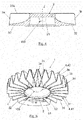
- FIGS 4 and 5 are sectional and perspective views of the heat sink (1), respectively, in which its geometry can be seen more clearly.
- the central body (2) comprises an inner hollow space (21) configured to house the electrical component (100) or a part of it, in this case, being the light-emitting board of the lamp.
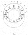
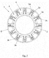
- FIGS. 6 and 7 are perspective and plan views of the heat sink of the present invention, respectively, in accordance with a second embodiment.
- the heat sink (1) is housed inside a cylindrical casing (6) that collects some of the heat of the flaps (3a, 3b) to dissipate it into the air, taking advantage of its greater surface area for heat transfer.
- the first flaps (3a) and second flaps (3b) extend from the central body (2) and are distributed around an axis (Z) to dissipate the heat generated by an electrical component (100), which is not represented.
- the flaps (3a, 3b) resemble connection ribs that link to another heat transfer element, in order to create thermal conduction bridges which favor heat dissipation.
- first flaps (3a) and the second flaps (3b) are arranged in an alternating way, there being tilting between the adjacent flaps (3a, 3b) according to a first plane (V) that is parallel to the axis (Z), to enable the heat sink to be demolded after it undergoes the injection manufacturing process.
Landscapes
- Engineering & Computer Science (AREA)
- General Engineering & Computer Science (AREA)
- Physics & Mathematics (AREA)
- Microelectronics & Electronic Packaging (AREA)
- Optics & Photonics (AREA)
- Manufacturing & Machinery (AREA)
- Mechanical Engineering (AREA)
- Thermal Sciences (AREA)
- Cooling Or The Like Of Electrical Apparatus (AREA)
- Cooling Or The Like Of Semiconductors Or Solid State Devices (AREA)
- Arrangement Of Elements, Cooling, Sealing, Or The Like Of Lighting Devices (AREA)
Priority Applications (1)
| Application Number | Priority Date | Filing Date | Title |
|---|---|---|---|
| PL16189209T PL3144591T3 (pl) | 2015-09-18 | 2016-09-16 | Rozpraszacz ciepła |
Applications Claiming Priority (1)
| Application Number | Priority Date | Filing Date | Title |
|---|---|---|---|
| ES201531335A ES2565556B1 (es) | 2015-09-18 | 2015-09-18 | Disipador de calor |
Publications (2)
| Publication Number | Publication Date |
|---|---|
| EP3144591A1 true EP3144591A1 (de) | 2017-03-22 |
| EP3144591B1 EP3144591B1 (de) | 2018-06-20 |
Family
ID=55588739
Family Applications (1)
| Application Number | Title | Priority Date | Filing Date |
|---|---|---|---|
| EP16189209.6A Not-in-force EP3144591B1 (de) | 2015-09-18 | 2016-09-16 | Kühlkörper |
Country Status (6)
| Country | Link |
|---|---|
| EP (1) | EP3144591B1 (de) |
| DK (1) | DK3144591T3 (de) |
| ES (2) | ES2565556B1 (de) |
| MX (1) | MX2016011948A (de) |
| PL (1) | PL3144591T3 (de) |
| PT (1) | PT3144591T (de) |
Families Citing this family (1)
| Publication number | Priority date | Publication date | Assignee | Title |
|---|---|---|---|---|
| US11448389B1 (en) * | 2022-02-17 | 2022-09-20 | Dialight Corporation | Luminaires with modular heat spreader panels |
Citations (5)
| Publication number | Priority date | Publication date | Assignee | Title |
|---|---|---|---|---|
| JPH09293410A (ja) * | 1996-04-30 | 1997-11-11 | Matsushita Electric Works Ltd | ダウンライト |
| EP1467146A2 (de) * | 2003-04-10 | 2004-10-13 | Osram Sylvania Inc. | LED-Lampe mit einsteckbaren, axialen Kabelkanälen und Verfahren zu deren Herstellung |
| EP1510754A2 (de) * | 2003-08-25 | 2005-03-02 | Osram Sylvania Inc. | LED-Lampe mit einsteckbaren Substraten und Verfahren zu deren Herstellung |
| WO2011138363A1 (en) * | 2010-05-05 | 2011-11-10 | Alexiou & Tryde Holding Aps | Led lamp assembly |
| EP2469160A1 (de) * | 2010-07-05 | 2012-06-27 | Toshiba Lighting&Technology Corporation | Beleuchtungsvorrichtung |
Family Cites Families (5)
| Publication number | Priority date | Publication date | Assignee | Title |
|---|---|---|---|---|
| US6308771B1 (en) * | 1998-10-29 | 2001-10-30 | Advanced Thermal Solutions, Inc. | High performance fan tail heat exchanger |
| US20030131970A1 (en) * | 2002-01-17 | 2003-07-17 | Carter Daniel P. | Heat sinks and method of formation |
| JP5204180B2 (ja) * | 2010-09-08 | 2013-06-05 | 株式会社日本自動車部品総合研究所 | 車両用前照灯 |
| JP5729600B2 (ja) * | 2011-03-25 | 2015-06-03 | 東芝ライテック株式会社 | 照明器具 |
| CN202915302U (zh) * | 2012-10-11 | 2013-05-01 | 四川畅洋泰鼎科技有限公司 | 筒灯散热体 |
-
2015
- 2015-09-18 ES ES201531335A patent/ES2565556B1/es not_active Expired - Fee Related
-
2016
- 2016-09-14 MX MX2016011948A patent/MX2016011948A/es active IP Right Grant
- 2016-09-16 DK DK16189209.6T patent/DK3144591T3/en active
- 2016-09-16 EP EP16189209.6A patent/EP3144591B1/de not_active Not-in-force
- 2016-09-16 ES ES16189209.6T patent/ES2688423T3/es active Active
- 2016-09-16 PL PL16189209T patent/PL3144591T3/pl unknown
- 2016-09-16 PT PT16189209T patent/PT3144591T/pt unknown
Patent Citations (5)
| Publication number | Priority date | Publication date | Assignee | Title |
|---|---|---|---|---|
| JPH09293410A (ja) * | 1996-04-30 | 1997-11-11 | Matsushita Electric Works Ltd | ダウンライト |
| EP1467146A2 (de) * | 2003-04-10 | 2004-10-13 | Osram Sylvania Inc. | LED-Lampe mit einsteckbaren, axialen Kabelkanälen und Verfahren zu deren Herstellung |
| EP1510754A2 (de) * | 2003-08-25 | 2005-03-02 | Osram Sylvania Inc. | LED-Lampe mit einsteckbaren Substraten und Verfahren zu deren Herstellung |
| WO2011138363A1 (en) * | 2010-05-05 | 2011-11-10 | Alexiou & Tryde Holding Aps | Led lamp assembly |
| EP2469160A1 (de) * | 2010-07-05 | 2012-06-27 | Toshiba Lighting&Technology Corporation | Beleuchtungsvorrichtung |
Also Published As
| Publication number | Publication date |
|---|---|
| DK3144591T3 (en) | 2018-10-08 |
| ES2565556B1 (es) | 2017-01-25 |
| PT3144591T (pt) | 2018-10-22 |
| PL3144591T3 (pl) | 2019-06-28 |
| MX2016011948A (es) | 2018-03-13 |
| ES2688423T3 (es) | 2018-11-02 |
| EP3144591B1 (de) | 2018-06-20 |
| ES2565556A1 (es) | 2016-04-05 |
Similar Documents
| Publication | Publication Date | Title |
|---|---|---|
| KR101278313B1 (ko) | 히트 싱크 | |
| JP2012533183A (ja) | 電子的若しくは電気的部品のためのヒートシンク | |
| DE202012104495U1 (de) | LED-Birne mit der Möglichkeit zur Erhöhung der Wärmeabführleistung | |
| US20110030920A1 (en) | Heat Sink Structure | |
| CN107624152A (zh) | 用于照明器的塑料散热器 | |
| WO2009132430A1 (en) | Modular heat sink and method for fabricating same | |
| RU2592890C1 (ru) | Светодиодная лампа | |
| US9791219B2 (en) | Method of fabricating a heat sink | |
| EP3144591B1 (de) | Kühlkörper | |
| CN104457347A (zh) | 一种大功率平面发热体液冷散热装置及其制造方法 | |
| KR101348692B1 (ko) | 히트파이프 삽입형 고효율 방열장치 | |
| CN106550586B (zh) | 散热器 | |
| CN107795969A (zh) | 包括散热结构的照明器 | |
| US20160201892A1 (en) | Lamp Base with Heat Dissipation Structure and Lamp Thereof, and Illumination Device | |
| CN110914590A (zh) | 冷却体和车辆探照灯 | |
| KR101329225B1 (ko) | 방열기능이 개선된 압출용 알루미늄 방열판 구조 | |
| WO2010121428A1 (en) | Method of manufacturing heatsink with angled fins | |
| CN210694761U (zh) | 增加散热面积的塑料散热器 | |
| EP3330607A1 (de) | Led-glühlampe | |
| US20160123570A1 (en) | Solid-state illuminating apparatus having heat dissipating structure with large surface area | |
| KR20220153975A (ko) | 금속 3d 프린팅을 이용하여 히트 싱크를 제조하는 방법 | |
| CN203907546U (zh) | 一种led灯 | |
| JP2005057033A (ja) | ピンフィン型ヒートシンク及びその製造方法 | |
| KR20150025762A (ko) | 전기전자 부품의 방열을 위한 히트싱크 | |
| CN203243658U (zh) | 一种散热器 |
Legal Events
| Date | Code | Title | Description |
|---|---|---|---|
| PUAI | Public reference made under article 153(3) epc to a published international application that has entered the european phase |
Free format text: ORIGINAL CODE: 0009012 |
|
| AK | Designated contracting states |
Kind code of ref document: A1 Designated state(s): AL AT BE BG CH CY CZ DE DK EE ES FI FR GB GR HR HU IE IS IT LI LT LU LV MC MK MT NL NO PL PT RO RS SE SI SK SM TR |
|
| AX | Request for extension of the european patent |
Extension state: BA ME |
|
| 17P | Request for examination filed |
Effective date: 20170921 |
|
| RBV | Designated contracting states (corrected) |
Designated state(s): AL AT BE BG CH CY CZ DE DK EE ES FI FR GB GR HR HU IE IS IT LI LT LU LV MC MK MT NL NO PL PT RO RS SE SI SK SM TR |
|
| RIC1 | Information provided on ipc code assigned before grant |
Ipc: F21K 9/20 20160101ALI20171103BHEP Ipc: F21V 29/77 20150101ALI20171103BHEP Ipc: F21V 23/06 20060101AFI20171103BHEP Ipc: H01L 23/36 20060101ALI20171103BHEP Ipc: F21V 29/78 20150101ALI20171103BHEP Ipc: F21V 29/74 20150101ALI20171103BHEP Ipc: F21V 29/83 20150101ALI20171103BHEP Ipc: H01L 23/367 20060101ALN20171103BHEP Ipc: F21Y 115/10 20160101ALN20171103BHEP |
|
| RIC1 | Information provided on ipc code assigned before grant |
Ipc: F21V 29/78 20150101ALI20171113BHEP Ipc: F21V 29/74 20150101ALI20171113BHEP Ipc: F21K 9/20 20160101ALI20171113BHEP Ipc: F21Y 115/10 20160101ALN20171113BHEP Ipc: H01L 23/367 20060101ALN20171113BHEP Ipc: F21V 23/06 20060101AFI20171113BHEP Ipc: H01L 23/36 20060101ALI20171113BHEP Ipc: F21V 29/83 20150101ALI20171113BHEP Ipc: F21V 29/77 20150101ALI20171113BHEP |
|
| GRAP | Despatch of communication of intention to grant a patent |
Free format text: ORIGINAL CODE: EPIDOSNIGR1 |
|
| INTG | Intention to grant announced |
Effective date: 20180115 |
|
| GRAS | Grant fee paid |
Free format text: ORIGINAL CODE: EPIDOSNIGR3 |
|
| GRAA | (expected) grant |
Free format text: ORIGINAL CODE: 0009210 |
|
| AK | Designated contracting states |
Kind code of ref document: B1 Designated state(s): AL AT BE BG CH CY CZ DE DK EE ES FI FR GB GR HR HU IE IS IT LI LT LU LV MC MK MT NL NO PL PT RO RS SE SI SK SM TR |
|
| REG | Reference to a national code |
Ref country code: GB Ref legal event code: FG4D |
|
| REG | Reference to a national code |
Ref country code: IE Ref legal event code: FG4D |
|
| REG | Reference to a national code |
Ref country code: AT Ref legal event code: REF Ref document number: 1010865 Country of ref document: AT Kind code of ref document: T Effective date: 20180715 |
|
| REG | Reference to a national code |
Ref country code: DE Ref legal event code: R096 Ref document number: 602016003647 Country of ref document: DE |
|
| REG | Reference to a national code |
Ref country code: RO Ref legal event code: EPE |
|
| REG | Reference to a national code |
Ref country code: FR Ref legal event code: PLFP Year of fee payment: 3 |
|
| REG | Reference to a national code |
Ref country code: DK Ref legal event code: T3 Effective date: 20181001 |
|
| REG | Reference to a national code |
Ref country code: SE Ref legal event code: TRGR |
|
| REG | Reference to a national code |
Ref country code: NL Ref legal event code: FP |
|
| REG | Reference to a national code |
Ref country code: PT Ref legal event code: SC4A Ref document number: 3144591 Country of ref document: PT Date of ref document: 20181022 Kind code of ref document: T Free format text: AVAILABILITY OF NATIONAL TRANSLATION Effective date: 20180918 |
|
| PG25 | Lapsed in a contracting state [announced via postgrant information from national office to epo] |
Ref country code: FI Free format text: LAPSE BECAUSE OF FAILURE TO SUBMIT A TRANSLATION OF THE DESCRIPTION OR TO PAY THE FEE WITHIN THE PRESCRIBED TIME-LIMIT Effective date: 20180620 Ref country code: BG Free format text: LAPSE BECAUSE OF FAILURE TO SUBMIT A TRANSLATION OF THE DESCRIPTION OR TO PAY THE FEE WITHIN THE PRESCRIBED TIME-LIMIT Effective date: 20180920 Ref country code: LT Free format text: LAPSE BECAUSE OF FAILURE TO SUBMIT A TRANSLATION OF THE DESCRIPTION OR TO PAY THE FEE WITHIN THE PRESCRIBED TIME-LIMIT Effective date: 20180620 |
|
| REG | Reference to a national code |
Ref country code: ES Ref legal event code: FG2A Ref document number: 2688423 Country of ref document: ES Kind code of ref document: T3 Effective date: 20181102 |
|
| REG | Reference to a national code |
Ref country code: NO Ref legal event code: T2 Effective date: 20180620 |
|
| REG | Reference to a national code |
Ref country code: LT Ref legal event code: MG4D |
|
| PG25 | Lapsed in a contracting state [announced via postgrant information from national office to epo] |
Ref country code: RS Free format text: LAPSE BECAUSE OF FAILURE TO SUBMIT A TRANSLATION OF THE DESCRIPTION OR TO PAY THE FEE WITHIN THE PRESCRIBED TIME-LIMIT Effective date: 20180620 Ref country code: HR Free format text: LAPSE BECAUSE OF FAILURE TO SUBMIT A TRANSLATION OF THE DESCRIPTION OR TO PAY THE FEE WITHIN THE PRESCRIBED TIME-LIMIT Effective date: 20180620 Ref country code: GR Free format text: LAPSE BECAUSE OF FAILURE TO SUBMIT A TRANSLATION OF THE DESCRIPTION OR TO PAY THE FEE WITHIN THE PRESCRIBED TIME-LIMIT Effective date: 20180921 Ref country code: LV Free format text: LAPSE BECAUSE OF FAILURE TO SUBMIT A TRANSLATION OF THE DESCRIPTION OR TO PAY THE FEE WITHIN THE PRESCRIBED TIME-LIMIT Effective date: 20180620 |
|
| PGFP | Annual fee paid to national office [announced via postgrant information from national office to epo] |
Ref country code: NL Payment date: 20180725 Year of fee payment: 17 Ref country code: TR Payment date: 20180926 Year of fee payment: 3 Ref country code: BE Payment date: 20180925 Year of fee payment: 3 |
|
| REG | Reference to a national code |
Ref country code: AT Ref legal event code: MK05 Ref document number: 1010865 Country of ref document: AT Kind code of ref document: T Effective date: 20180620 |
|
| REG | Reference to a national code |
Ref country code: NO Ref legal event code: CHAD Owner name: SIMON, ES |
|
| PG25 | Lapsed in a contracting state [announced via postgrant information from national office to epo] |
Ref country code: CZ Free format text: LAPSE BECAUSE OF FAILURE TO SUBMIT A TRANSLATION OF THE DESCRIPTION OR TO PAY THE FEE WITHIN THE PRESCRIBED TIME-LIMIT Effective date: 20180620 Ref country code: IS Free format text: LAPSE BECAUSE OF FAILURE TO SUBMIT A TRANSLATION OF THE DESCRIPTION OR TO PAY THE FEE WITHIN THE PRESCRIBED TIME-LIMIT Effective date: 20181020 Ref country code: EE Free format text: LAPSE BECAUSE OF FAILURE TO SUBMIT A TRANSLATION OF THE DESCRIPTION OR TO PAY THE FEE WITHIN THE PRESCRIBED TIME-LIMIT Effective date: 20180620 Ref country code: AT Free format text: LAPSE BECAUSE OF FAILURE TO SUBMIT A TRANSLATION OF THE DESCRIPTION OR TO PAY THE FEE WITHIN THE PRESCRIBED TIME-LIMIT Effective date: 20180620 Ref country code: SK Free format text: LAPSE BECAUSE OF FAILURE TO SUBMIT A TRANSLATION OF THE DESCRIPTION OR TO PAY THE FEE WITHIN THE PRESCRIBED TIME-LIMIT Effective date: 20180620 |
|
| PGFP | Annual fee paid to national office [announced via postgrant information from national office to epo] |
Ref country code: NO Payment date: 20181009 Year of fee payment: 3 Ref country code: PT Payment date: 20181019 Year of fee payment: 3 Ref country code: RO Payment date: 20181012 Year of fee payment: 3 |
|
| PG25 | Lapsed in a contracting state [announced via postgrant information from national office to epo] |
Ref country code: SM Free format text: LAPSE BECAUSE OF FAILURE TO SUBMIT A TRANSLATION OF THE DESCRIPTION OR TO PAY THE FEE WITHIN THE PRESCRIBED TIME-LIMIT Effective date: 20180620 |
|
| REG | Reference to a national code |
Ref country code: DE Ref legal event code: R097 Ref document number: 602016003647 Country of ref document: DE |
|
| PLBE | No opposition filed within time limit |
Free format text: ORIGINAL CODE: 0009261 |
|
| STAA | Information on the status of an ep patent application or granted ep patent |
Free format text: STATUS: NO OPPOSITION FILED WITHIN TIME LIMIT |
|
| PG25 | Lapsed in a contracting state [announced via postgrant information from national office to epo] |
Ref country code: MC Free format text: LAPSE BECAUSE OF FAILURE TO SUBMIT A TRANSLATION OF THE DESCRIPTION OR TO PAY THE FEE WITHIN THE PRESCRIBED TIME-LIMIT Effective date: 20180620 |
|
| PGFP | Annual fee paid to national office [announced via postgrant information from national office to epo] |
Ref country code: IE Payment date: 20190104 Year of fee payment: 3 |
|
| 26N | No opposition filed |
Effective date: 20190321 |
|
| PG25 | Lapsed in a contracting state [announced via postgrant information from national office to epo] |
Ref country code: LU Free format text: LAPSE BECAUSE OF NON-PAYMENT OF DUE FEES Effective date: 20180916 |
|
| PG25 | Lapsed in a contracting state [announced via postgrant information from national office to epo] |
Ref country code: SI Free format text: LAPSE BECAUSE OF FAILURE TO SUBMIT A TRANSLATION OF THE DESCRIPTION OR TO PAY THE FEE WITHIN THE PRESCRIBED TIME-LIMIT Effective date: 20180620 |
|
| PGFP | Annual fee paid to national office [announced via postgrant information from national office to epo] |
Ref country code: IT Payment date: 20190930 Year of fee payment: 4 |
|
| PG25 | Lapsed in a contracting state [announced via postgrant information from national office to epo] |
Ref country code: AL Free format text: LAPSE BECAUSE OF FAILURE TO SUBMIT A TRANSLATION OF THE DESCRIPTION OR TO PAY THE FEE WITHIN THE PRESCRIBED TIME-LIMIT Effective date: 20180620 |
|
| PG25 | Lapsed in a contracting state [announced via postgrant information from national office to epo] |
Ref country code: MT Free format text: LAPSE BECAUSE OF NON-PAYMENT OF DUE FEES Effective date: 20180916 |
|
| REG | Reference to a national code |
Ref country code: DK Ref legal event code: EBP Effective date: 20190930 Ref country code: NO Ref legal event code: MMEP |
|
| PG25 | Lapsed in a contracting state [announced via postgrant information from national office to epo] |
Ref country code: RO Free format text: LAPSE BECAUSE OF NON-PAYMENT OF DUE FEES Effective date: 20190916 |
|
| REG | Reference to a national code |
Ref country code: CH Ref legal event code: PL |
|
| PG25 | Lapsed in a contracting state [announced via postgrant information from national office to epo] |
Ref country code: CY Free format text: LAPSE BECAUSE OF FAILURE TO SUBMIT A TRANSLATION OF THE DESCRIPTION OR TO PAY THE FEE WITHIN THE PRESCRIBED TIME-LIMIT Effective date: 20180620 Ref country code: HU Free format text: LAPSE BECAUSE OF FAILURE TO SUBMIT A TRANSLATION OF THE DESCRIPTION OR TO PAY THE FEE WITHIN THE PRESCRIBED TIME-LIMIT; INVALID AB INITIO Effective date: 20160916 Ref country code: MK Free format text: LAPSE BECAUSE OF NON-PAYMENT OF DUE FEES Effective date: 20180620 |
|
| PG25 | Lapsed in a contracting state [announced via postgrant information from national office to epo] |
Ref country code: NO Free format text: LAPSE BECAUSE OF NON-PAYMENT OF DUE FEES Effective date: 20190930 Ref country code: LI Free format text: LAPSE BECAUSE OF NON-PAYMENT OF DUE FEES Effective date: 20190930 Ref country code: CH Free format text: LAPSE BECAUSE OF NON-PAYMENT OF DUE FEES Effective date: 20190930 Ref country code: IE Free format text: LAPSE BECAUSE OF NON-PAYMENT OF DUE FEES Effective date: 20190916 |
|
| REG | Reference to a national code |
Ref country code: BE Ref legal event code: MM Effective date: 20190930 |
|
| PG25 | Lapsed in a contracting state [announced via postgrant information from national office to epo] |
Ref country code: BE Free format text: LAPSE BECAUSE OF NON-PAYMENT OF DUE FEES Effective date: 20190930 |
|
| PG25 | Lapsed in a contracting state [announced via postgrant information from national office to epo] |
Ref country code: PT Free format text: LAPSE BECAUSE OF NON-PAYMENT OF DUE FEES Effective date: 20200714 Ref country code: DK Free format text: LAPSE BECAUSE OF NON-PAYMENT OF DUE FEES Effective date: 20190930 |
|
| GBPC | Gb: european patent ceased through non-payment of renewal fee |
Effective date: 20200916 |
|
| PG25 | Lapsed in a contracting state [announced via postgrant information from national office to epo] |
Ref country code: GB Free format text: LAPSE BECAUSE OF NON-PAYMENT OF DUE FEES Effective date: 20200916 |
|
| PG25 | Lapsed in a contracting state [announced via postgrant information from national office to epo] |
Ref country code: IT Free format text: LAPSE BECAUSE OF NON-PAYMENT OF DUE FEES Effective date: 20200916 |
|
| PGFP | Annual fee paid to national office [announced via postgrant information from national office to epo] |
Ref country code: FR Payment date: 20210812 Year of fee payment: 6 |
|
| PGFP | Annual fee paid to national office [announced via postgrant information from national office to epo] |
Ref country code: DE Payment date: 20210810 Year of fee payment: 6 Ref country code: SE Payment date: 20210910 Year of fee payment: 6 Ref country code: PL Payment date: 20210804 Year of fee payment: 6 |
|
| PGFP | Annual fee paid to national office [announced via postgrant information from national office to epo] |
Ref country code: ES Payment date: 20211006 Year of fee payment: 6 |
|
| PG25 | Lapsed in a contracting state [announced via postgrant information from national office to epo] |
Ref country code: TR Free format text: LAPSE BECAUSE OF NON-PAYMENT OF DUE FEES Effective date: 20190916 |
|
| REG | Reference to a national code |
Ref country code: DE Ref legal event code: R119 Ref document number: 602016003647 Country of ref document: DE |
|
| REG | Reference to a national code |
Ref country code: SE Ref legal event code: EUG |
|
| REG | Reference to a national code |
Ref country code: NL Ref legal event code: MM Effective date: 20221001 |
|
| PG25 | Lapsed in a contracting state [announced via postgrant information from national office to epo] |
Ref country code: NL Free format text: LAPSE BECAUSE OF NON-PAYMENT OF DUE FEES Effective date: 20221001 |
|
| PG25 | Lapsed in a contracting state [announced via postgrant information from national office to epo] |
Ref country code: FR Free format text: LAPSE BECAUSE OF NON-PAYMENT OF DUE FEES Effective date: 20220930 Ref country code: DE Free format text: LAPSE BECAUSE OF NON-PAYMENT OF DUE FEES Effective date: 20230401 |
|
| PG25 | Lapsed in a contracting state [announced via postgrant information from national office to epo] |
Ref country code: SE Free format text: LAPSE BECAUSE OF NON-PAYMENT OF DUE FEES Effective date: 20220917 |
|
| REG | Reference to a national code |
Ref country code: ES Ref legal event code: FD2A Effective date: 20231027 |
|
| PG25 | Lapsed in a contracting state [announced via postgrant information from national office to epo] |
Ref country code: PL Free format text: LAPSE BECAUSE OF NON-PAYMENT OF DUE FEES Effective date: 20220916 |
|
| PG25 | Lapsed in a contracting state [announced via postgrant information from national office to epo] |
Ref country code: ES Free format text: LAPSE BECAUSE OF NON-PAYMENT OF DUE FEES Effective date: 20220917 |
|
| PG25 | Lapsed in a contracting state [announced via postgrant information from national office to epo] |
Ref country code: ES Free format text: LAPSE BECAUSE OF NON-PAYMENT OF DUE FEES Effective date: 20220917 |