EP3144422A2 - Method for monitoring weft traveling condition in air jet loom - Google Patents
Method for monitoring weft traveling condition in air jet loom Download PDFInfo
- Publication number
- EP3144422A2 EP3144422A2 EP16184668.8A EP16184668A EP3144422A2 EP 3144422 A2 EP3144422 A2 EP 3144422A2 EP 16184668 A EP16184668 A EP 16184668A EP 3144422 A2 EP3144422 A2 EP 3144422A2
- Authority
- EP
- European Patent Office
- Prior art keywords
- weft
- sensor
- yarn
- weft yarn
- release
- Prior art date
- Legal status (The legal status is an assumption and is not a legal conclusion. Google has not performed a legal analysis and makes no representation as to the accuracy of the status listed.)
- Granted
Links
- 238000000034 method Methods 0.000 title claims abstract description 15
- 238000012544 monitoring process Methods 0.000 title claims abstract description 14
- 238000003780 insertion Methods 0.000 claims abstract description 82
- 230000037431 insertion Effects 0.000 claims abstract description 82
- 239000004744 fabric Substances 0.000 claims abstract description 19
- 238000011144 upstream manufacturing Methods 0.000 claims abstract description 19
- 238000001514 detection method Methods 0.000 claims abstract description 15
- 238000002347 injection Methods 0.000 description 17
- 239000007924 injection Substances 0.000 description 17
- 238000009941 weaving Methods 0.000 description 8
- 235000014676 Phragmites communis Nutrition 0.000 description 3
- 230000003247 decreasing effect Effects 0.000 description 2
- 230000035939 shock Effects 0.000 description 2
- 230000003111 delayed effect Effects 0.000 description 1
- 238000012905 input function Methods 0.000 description 1
- 238000004804 winding Methods 0.000 description 1
Images


Classifications
-
- D—TEXTILES; PAPER
- D03—WEAVING
- D03D—WOVEN FABRICS; METHODS OF WEAVING; LOOMS
- D03D47/00—Looms in which bulk supply of weft does not pass through shed, e.g. shuttleless looms, gripper shuttle looms, dummy shuttle looms
- D03D47/28—Looms in which bulk supply of weft does not pass through shed, e.g. shuttleless looms, gripper shuttle looms, dummy shuttle looms wherein the weft itself is projected into the shed
- D03D47/30—Looms in which bulk supply of weft does not pass through shed, e.g. shuttleless looms, gripper shuttle looms, dummy shuttle looms wherein the weft itself is projected into the shed by gas jet
- D03D47/3066—Control or handling of the weft at or after arrival
- D03D47/3073—Detection means therefor
-
- D—TEXTILES; PAPER
- D03—WEAVING
- D03D—WOVEN FABRICS; METHODS OF WEAVING; LOOMS
- D03D47/00—Looms in which bulk supply of weft does not pass through shed, e.g. shuttleless looms, gripper shuttle looms, dummy shuttle looms
- D03D47/28—Looms in which bulk supply of weft does not pass through shed, e.g. shuttleless looms, gripper shuttle looms, dummy shuttle looms wherein the weft itself is projected into the shed
- D03D47/30—Looms in which bulk supply of weft does not pass through shed, e.g. shuttleless looms, gripper shuttle looms, dummy shuttle looms wherein the weft itself is projected into the shed by gas jet
- D03D47/3026—Air supply systems
- D03D47/3033—Controlling the air supply
- D03D47/304—Controlling of the air supply to the auxiliary nozzles
Definitions
- the present invention relates to a method for monitoring a weft traveling condition in an air jet loom.
- a weft yarn of a predetermined length fed from a weft package and stored on a weft yarn measuring and storing device is released therefrom to be inserted into a warp shed by a weft insertion nozzle and conveyed throughout the weaving width of the air jet loom by a plurality of sub-nozzles. It is known in the art that the releasing of a weft yarn by the weft insertion nozzle and conveying of the weft yarn by the sub-nozzles is controlled by monitoring the weft traveling condition within the weaving width.
- Japanese Patent Application Publication H04-240249 discloses a weft insertion control device of an air jet loom that intends to control the weft insertion to prevent the weft insertion failure without increasing unnecessary air consumption.
- the air jet loom includes a main nozzle that inserts a weft yarn into a weft passage by an air jet and a plurality of sub-nozzles that are disposed at a specific interval along the weft passage and conveys the weft yarn through the weft passage by air jets.
- the weft insertion control device has a weft release sensor that is disposed adjacent to the storage drum and detects the weft release time at which the weft is released from the storage drum during the weft insertion.
- a weft arrival sensor is disposed at an end of a woven cloth that is opposite from the main nozzle and detects the time of arrival of the weft yarn at the other end of the woven cloth. The air injection pressure of the main nozzle is controlled so that the weft release time detected by the weft release sensor coincides with a target time.
- the air injection pressure of the sub-nozzles is controlled so that the time difference between the weft release time and the weft arrival time coincides with a target time difference so as to minimize the loosening of the weft during the weft insertion.
- the target time difference is changed to the decreased time difference so that an increase of air consumption is forestalled.
- the present invention which has been made in light of the above-described problems, is directed to providing a method for monitoring the traveling condition of a weft yarn precisely.
- a method for monitoring weft traveling condition in an air jet loom including a weft measuring and storing device that has a storage drum for a weft yarn, a weft stop pin that releases and stop the weft yarn, and a balloon sensor that detects the release of the weft yarn.
- the air jet loom further includes a weft insertion nozzle, a plurality of sub-nozzles, a brake that applies braking to the weft yarn before the weft insertion ends, and a weft sensor that is disposed within a width of cloth to be woven by the air jet loom so as to detect the weft yarn.
- the weft sensor is disposed upstream of a leading end position of the weft yarn to be located at a braking start timing of the brake with respect to a weft insertion direction.
- the weft traveling condition is monitored by grasping a time difference between a weft passage timing given by a weft detection signal generated by the weft sensor and a weft release timing given by a weft release signal generated by the balloon sensor.
- the weft release timing is when the weft yarn is released from the storage drum by a length that extends along the weft insertion direction from an end of the cloth closest to an upstream end of the traveling passage with respect to the weft insertion direction to the weft sensor.
- upstream and downstream will be used to indicate directions with respect to the movement of a weft yarn for insertion through a warp shed. Specifically, “upstream” indicates the direction in which a weft yarn is inserted and travels in a shed, while “downstream” indicates the opposite direction.
- the weft insertion device 1 includes a weft insertion nozzle 2, a yarn supply package 3 that is disposed upstream of the weft insertion nozzle 2, a weft measuring and storage device 4 and a reed 5 that is disposed downstream of the weft insertion nozzle 2 and has a plurality of dents and a weft traveling passage 6 formed by the dents, and a plurality of sub-nozzles 7 that are arranged along the weft traveling passage 6 of the reed 5.
- the weft measuring and storage device 4 includes a weft stop pin 9 and a balloon sensor 10 that detects a release of a weft yarn Y. As shown in Fig. 1B , the weft stop pin 9 and the balloon sensor 10 are arranged around the storage drum 8, and the balloon sensor 10 is disposed in side-by-side relation to the weft stop pin 9 on the weft releasing side (arrow direction in Fig. 1B ) of the weft stop pin 9.
- the weft stop pin 9 is electrically connected to a control device 16 via a wire 20, and the weft yarn Y stored on the storage drum 8 is released when the air jet loom is rotated to a predetermined angular position that is preset in the control device 16.
- the timing at which the weft stop pin 9 is actuated to release the weft yarn Y corresponds to the start of weft insertion.
- the balloon sensor 10 is electrically connected to the control device 16 via a wire 21.
- the balloon sensor 10 detects a weft yarn Y being released from the storage drum 8 during the weft insertion and generates a weft yarn release signal to the control device 16.
- the control device 16 After a specific number of weft yarn release signals (three times in the present embodiment) has been generated by the balloon sensor 10, the control device 16 causes the weft stop pin 9 to engage with the storage drum 8 so as to stop the release of weft yarn Y from the storage drum 8, thus a weft insertion being ended.
- the operation timing of the weft stop pin 9 to stop the weft yarn Y is set depending on the number of turns of weft yarn Y to be wound around the storage drum 8 that is required for the storage of a predetermined length of the weft yarn Y corresponding to the weaving width of the air jet loom.
- the control device 16 is configured to send a signal to the weft stop pin 9 to stop the weft yarn Y upon receiving the weft yarn release signals for three times from the balloon sensor 10.
- the weft yarn release signal, or a signal generated by the balloon sensor 10 and representing a release of a weft yarn Y from the storage drum 8, corresponds to the weft detection signal of the present invention.
- the control device 16 recognizes the weft release timing based on a signal transmitted by an encoder 17 and representing a specific angular position of the loom.
- the weft insertion nozzle 2 includes a tandem nozzle 11 that pulls out a weft yarn Y from the storage drum 8 and a main nozzle 12 that inserts the weft yarn Y into the weft traveling passage 6.
- the sub-nozzle 7 assists the inserted weft yarn Y in flying through the weft traveling passage 6.
- a brake 13 is disposed upstream of the tandem nozzle 11 to apply braking to the weft yarn Y before the weft insertion ends. Any conventional brake such as a mechanical brake or air brake may be used for the brake 13.
- the main nozzle 12, sub-nozzles 7 and the reed 5 are mounted to a slay (not shown) and make reciprocating back and forth motion.
- the tandem nozzle 11, the brake 13, the weft measuring and storage device 4 and the yarn supply package 3 are fixed to a bracket that is mounted to a frame (not shown) of the air jet loom or a floor surface (not shown).
- An end sensor 14 is provided at a position corresponding to the downstream end of the weft traveling passage 6.
- the end sensor 14 detects the arrival of a weft yarn Y at a position adjacent to an end of a woven cloth that is opposite from the main nozzle 12.
- the end sensor 14 is electrically connected via a wire 15 to the control device 16, which determines whether or the weft insertion has been made successful or failed based on the presence or absence of a weft detection signal from the end sensor 14.
- the weft detection signal from the end sensor 14 indicates the arrival of a weft yarn Y at the downstream end of a woven cloth, which is recognized as the timing of weft insertion end based on a signal generated by the control device 16 and representing the angular position of the air jet loom.
- a weft sensor 18 is disposed near the weft traveling passage within the width TL of cloth to be woven by the air jet loom so as to detect a weft yarn passing through the weft traveling passage 6 at a position that is upstream of the end sensor 14.
- the weft sensor 18 is electrically connected to the control device 16 via a wire 19.
- the weft detection signal from the weft sensor 18 is recognized by the control device 16 as the passage timing of the leading end of a weft yarn Y at the position of the weft sensor 18 based on the signal generated by the encoder 17 and representing the angular position of the air jet loom.
- the present embodiment is described as having only one set of the weft insertion device 1, two or more weft insertion devices may be used to provide a multicolor weft insertion device. It is noted that the multicolor weft insertion device includes a device inserts a plurality of different weft yarns of the same color. In such multicolor weft insertion device, the sub-nozzles 7 are used common for plural sets of weft insertion device 1.
- the main nozzle 12 is connected via a pipe 23 to a main valve 22 that controls the supply of compressed air.
- the tandem nozzle 11 is connected via a pipe 25 to a tandem valve 24 that controls the supply of compressed air.
- the main valve 22 and the tandem valve 24 are connected to a main air tank 27 via pressure meter 29, a main regulator 30, a source pressure meter 31 and a filter 32 to a common air compressor 33 that is installed in the weaving factory. Compressed air supplied from the air compressor 33 is adjusted to a specific pressure by the main regulator 30 and stored in the main air tank 27. The pressure of the compressed air that is supplied to the main air tank 27 is constantly monitored by the main pressure meter 29.
- the sub-nozzles 7 are divided into six groups each including four sub-nozzles 7 and a sub-valve 34 is connected to the sub-nozzles 7 of each group via a pipe 35.
- the number of the sub-nozzle groups is not limited to six, but any suitable number of the sub-nozzle groups may be provided depending on the weaving width, and a plurality of sub-valves 34 may be provided for each sub-nozzle group.
- the sub-nozzle groups are connected to a common sub-air tank 34.
- the sub-air tank 36 is connected to a sub-regulator 39 via a pipe 37 and a sub-pressure meter 38.
- the sub-regulator 39 is connected to a pipe 41 that provide a connection between the main pressure meter 29 and the main regulator 30 by a pipe 40.
- Compressed air from the air compressor 33 is adjusted to a specific pressure by the sub-regulator 39 and stored in the sub-air tank 36.
- the pressure of the compressed air that is supplied to the sub-air tank 36 is constantly monitored by the sub-pressure meter 38.
- the main valve 22, the tandem valve 24, the sub-valve 34, the source pressure meter 31, the main pressure meter 29, the sub-pressure meter 38 and the brake 13 are electrically connected to the control device 16 via the wires 42, 43, 44, 45, 46, 47, 48, respectively.
- the timings and durations for the respective operations of the main valve 22, the tandem valve 24, the sub-valve 34 and the brake 13 are preset in the control device 16.
- the control device 16 receives signals from the source pressure meter 31 and the main pressure meter 29 and the sub-pressure meter 38.
- the control device 16 generates a signal to the main valve 22 and the tandem valve 24 before the weft insertion start timing at which the weft stop pin 9 is actuated for weft yarn releasing operation, so that air is injected from the main nozzle 12 and the tandem nozzle 11.
- the control device 16 also generates a signal to the brake 13 before the weft insertion end timing at which the weft stop pin 9 stops the weft yarn Y on the storage drum 8.
- the brake 13 applies braking to the weft yarn Y traveling at high speed so as to reduce the impact on the weft yarn Y at the end of the weft insertion.
- the control device 16 is equipped with a display device 49 having a display and input function.
- the display device 49 has a display (not shown) on which various line charts, as shown in Figs 2 through 4 , various information and data are displayed, and entry and renewal of information and data can be made on the display.
- the end sensor 14 and the weft sensor 18 within the weaving width are indicated at positions above the upper line (a), and the weft release timings B1, B2, B3 of the weft yarn Y given by a weft release signal generated by the balloon sensor 10, a weft passage timing IS of the weft yarn Y given by a weft detection signal generated by the weft sensor 18, the weft insertion end timing IE detected by the end sensor 14, and the braking start timing BT of application of the brake 13 are indicated on the lower line (b).
- L, 2L and 3L on the upper line (a) represent the positions of the leading end of a weft yarn Y that correspond to the lengths of the weft yarn Y for one turn, two turns and three turns around the storage drum 8, respectively, as measured from the upstream end of the width TL of cloth.
- the weft yarn Y is released from the storage drum 8 by a length that extends along the weft insertion direction from an end of the cloth closest to the upstream end of the weft traveling passage 6 with respect to the weft insertion direction to the weft sensor 18.
- the leading end of the weft yarn Y is positioned at the positions L, 2L, 3L at the second, third weft release timings B2, B3 and the weft insertion end timing IE at which the second, third weft release signals generated by the balloon sensor 10 and a weft detection signal generated by the end sensor 14, respectively.
- the positions L, 2L, 3L will be referred to as the ideal leading end positions L, 2L, 3L in the following description of the embodiment.
- the weft release timings B1 through B3 on the line (b) represents the angular positions of the loom corresponding to the first, second, third weft release signals from the balloon sensor 10, respectively. It is noted that the angular positions of the loom for the respective weft release signals can be obtained from signals of the encoder 17.
- the weft insertion end timing IE corresponds to the angular position of the loom when the end sensor 14 generates a weft detection signal.
- the braking start timing BT is preset in the control device 16 at such an angular position of the loom that the weft yarn Y is braked before the weft insertion end timing IE.
- the weft sensor 18 is disposed upstream of the leading end position BL of a weft yarn Y within the width TL of cloth to be located at the braking start timing BT of the brake 13 with respect to the weft insertion direction. That is, the weft sensor 18 is disposed upstream of the leading end position BL of the weft yarn Y that is estimated from the braking start timing BT and the speed of the weft yarn Y.
- the weft sensor 18 is disposed at the ideal leading end position 2L of a weft yarn Y with a length that corresponds to two turns of the weft yarn around the storage drum 8 as measured from the position corresponding to the upstream end of the woven cloth.
- the weft sensor 18 is disposed at an ideal leading end position that is closest to the leading end position of the weft yarn to be located at the braking start timing of the brake 13 so as to detect the ideal leading end position of the weft yarn Y at a weft release signal generated by the balloon sensor 10.
- the weft yarn Y may be loosened, with the result that the weft passage timing IS of the weft yarn Y is delayed by a time difference ⁇ as shown in FIG. 2 .
- the traveling condition of a weft yarn Y in the weft traveling passage 6 may be monitored by grasping such time difference ⁇ between the weft passage timing IS and the third weft release timing B3.
- the third weft release timing B3 takes place immediately before the braking start timing BT of the brake13.
- the weft sensor 18 detects the traveling condition of the weft yarn Y before it is braked by the brake 13. Merely by monitoring the time difference ⁇ between the weft passage timing IS of the weft yarn Y and the third weft release signal from the balloon sensor 10, or the third weft release timing B3, the estimation of weft release timing, which will be described later, is not required, so that the weft insertion device 1 of the present embodiment is controlled more easily as compared with the case in which a sensor such as the weft sensor 18 is not provided at the ideal leading end position 2L.
- the traveling condition of the weft yarn Y is indicated by the curve YF.
- Five positions of the leading end of the weft yarn Y are detected by stroboscopic technique, and the curve YF is made by plotting the data of strobe timings ST1 through ST5 obtained by the stroboscopic detection.
- the strobe timing ST1 corresponds to the weft insertion start timing at which the weft stop pin 9 releases the weft yarn Y
- the strobe timing ST5 corresponds to the weft insertion end timing IE.
- the first weft release timing B1 occurs later than the strobe timing ST1 because the balloon sensor 10 is located at a position that is downstream of the weft stop pin 9 with respect to the direction in which the weft yarn Y is released from the weft stop pin 9.
- the curve YF does not show much difference in the weft release performance of the weft insertion nozzle 2 and the weft conveyance performance of the sub-nozzles 7 among different types of weft yarn Y and the difference in pressure of the weft insertion nozzle 2 and the sub-nozzles 7.
- the weft passage timing IS is used to monitor the traveling condition of the weft yarn Y, so that any change in traveling condition of the weft yarn Y occurring due to the use of different types of the weft yarn Y and the air jets of different pressure from the weft insertion nozzle 2 and the sub-nozzles 7 may be grasped without being affected by the braking action of the brake 13.
- the change in the weft yarn traveling condition may be monitored by grasping the time difference ⁇ between the weft passage timing IS detected by the weft sensor 18 and the third weft release timing B3 detected by the balloon sensor 10.
- the balance between the weft release performance of the weft insertion nozzle 2 and the weft conveyance performances of the sub-nozzle 7 may be precisely determined, which contributes greatly for setting and controlling of the compressed air pressure and the operation timing of the weft insertion nozzle 2 and the sub-nozzles 7.
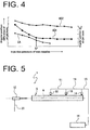
- the following will describe a method for setting the air injection pressure of the sub-nozzles 7 with reference to Fig. 4 , as an example of the method for controlling the weft insertion device 1 utilizing the monitoring of the weft travel condition based on the time difference ⁇ between the weft passage timing IS and the third weft release timing B3.
- the curve AD1 shows the time difference ⁇ between the weft passage timing IS and the third weft release timing B3 of the weft yarn Y that varies according to the change of air injection pressure of the sub-nozzles 7 with the weft insertion end timing IE fixed constant through the adjustment of the air injection pressure of the weft insertion nozzles 2.
- the curve AD2 shows the time difference ⁇ occurring between the weft insertion end timing IE detected by the end sensor 14 and the weft release end timing that is estimated based on the weft release signal from the balloon sensor 10 and varying according to the air injection pressure of the sub-nozzles 7.
- the weft release end timing is determined by adding the third weft release timing B3 that is detected by the balloon sensor 10 to a weft release duration from the release of the weft yarn Y to the weft stop pin 9 that is predetermined before the determination of the weft release timing.
- the change in the air injection pressure of the sub-nozzles 7 causes a relatively small change in the time difference ⁇ of the curve AD2, as compared with the curve AD1 that shows greater change in the time difference ⁇ .
- Such difference between the curves AD1 and AD2 is due to whether it is before or after the weft yarn Y is subjected to the braking of the brake 13 when the weft yarn arrival timing and the weft release timing are detected, and the curve AD1 shows more clear change in the weft yarn traveling condition due to the use of different types of the weft yarn Y and the different air injection pressures.
- the balance between the weft release performance of the weft insertion nozzle 2 and the conveyance performances of the sub-nozzles 7 is determined more precisely from the curve AD1.
- the air injection pressure of the sub-nozzles 7 before the time difference ⁇ is greatly changed on the curve AD1 may be set as the optimum air injection pressure SP of the sub-nozzles 7.
- the weft insertion device 1 in which the method of the second embodiment is performed includes two weft sensors 18, 50 at two positions near the weft traveling passage 6 within the width TL of the cloth.
- the weft sensor 18 is substantially the same as the counterpart sensor shown in Fig. 2 .
- the weft sensor 50 is disposed at the ideal leading end position L of the weft yarn Y near the weft traveling passage 6, which corresponds to the second weft release timing B2 based on the second weft yarn release signal from the balloon sensor 10.
- the weft sensor 50 is disposed upstream of the weft sensor 18 and electrically connected to the control device 16 via a wire 51.
- the weft sensor 50 detects the weft yarn Y before the braking start timing BT at which the operation of the brake 13 is started, so that the changes in the traveling condition of the weft yarn Y due to the use of different types of the weft yarn Y and the different air injection pressure of the weft insertion nozzle 2 and the sub-nozzle 7 may be monitored before the weft yarn Y is braked by the brake 13, as in the case of the first embodiment.
- the detection of the weft yarn Y at two different positions by the weft sensors 18, 50 permits monitoring of the weft yarn traveling condition more precisely, so that the control of the release performance and the conveyance performance of the weft yarn Y may be improved.
- a method for monitoring weft traveling condition in an air jet loom that includes a weft measuring and storing device having a drum, a weft stop pin, and a balloon sensor that detects the release of the weft yarn.
- the air jet loom further includes a weft insertion nozzle, a plurality of sub-nozzles, a brake, and a weft sensor that is disposed within a width of cloth.
- the weft sensor is disposed upstream of a position of leading end of the weft yarn corresponding to a brake timing of the brake in weft insertion direction.
- the weft traveling condition is monitored by grasping a time difference between a weft passage timing given by a weft detection signal generated by the weft sensor and a weft release timing given by a weft release signal generated by the balloon sensor.
Landscapes
- Engineering & Computer Science (AREA)
- Textile Engineering (AREA)
- Looms (AREA)
Abstract
Description
- The present invention relates to a method for monitoring a weft traveling condition in an air jet loom.
- In an air jet loom, a weft yarn of a predetermined length fed from a weft package and stored on a weft yarn measuring and storing device is released therefrom to be inserted into a warp shed by a weft insertion nozzle and conveyed throughout the weaving width of the air jet loom by a plurality of sub-nozzles. It is known in the art that the releasing of a weft yarn by the weft insertion nozzle and conveying of the weft yarn by the sub-nozzles is controlled by monitoring the weft traveling condition within the weaving width.
- Japanese Patent Application Publication
H04-240249 - The weft insertion control device has a weft release sensor that is disposed adjacent to the storage drum and detects the weft release time at which the weft is released from the storage drum during the weft insertion. In addition, a weft arrival sensor is disposed at an end of a woven cloth that is opposite from the main nozzle and detects the time of arrival of the weft yarn at the other end of the woven cloth. The air injection pressure of the main nozzle is controlled so that the weft release time detected by the weft release sensor coincides with a target time.
- The air injection pressure of the sub-nozzles is controlled so that the time difference between the weft release time and the weft arrival time coincides with a target time difference so as to minimize the loosening of the weft during the weft insertion. In addition, it is so configured that, when the time difference is decreased below a specific time different due to a change in the air injection pressure, the target time difference is changed to the decreased time difference so that an increase of air consumption is forestalled.
- In recent years, an increasing number of high-speed air jet looms running at 1000 rpm or higher are used. In such an air jet loom running at a high speed, the flying speed of the weft yarn is high and, therefore, the weft yarn may be subjected to a great shock of impact at the end of the weft insertion, which may cause a break to the weft yarn due to such shock of impact. In order to relieve such impact, a weft yarn brake is commonly used for application of brake to the weft yarn before the end of the weft insertion.
- In an air jet loom having a weft yarn brake, the change of the weft yarn traveling condition during the period of time after braking and before the end of weft insertion that is due to the use of different types of weft yarn and any change of the air injection pressure of the weft insertion nozzle and the sub-nozzles hardly appears. In the case of the weft insertion device of the above-cited Publication in which the time difference between the arrival time of the weft and the release time of the weft yarn from the storage drum are detected, detection of the weft arrival time is made after the weft is braked, so that the change in the travelling condition of the weft yarn due to the use of different types of weft yarns and the change of the air injection pressure of the weft insertion nozzle and the sub-nozzles becomes less obvious and, consequently, the precise monitoring of the weft traveling condition becomes difficult.
- The present invention, which has been made in light of the above-described problems, is directed to providing a method for monitoring the traveling condition of a weft yarn precisely.
- In accordance with an aspect of the present invention, there is provided a method for monitoring weft traveling condition in an air jet loom including a weft measuring and storing device that has a storage drum for a weft yarn, a weft stop pin that releases and stop the weft yarn, and a balloon sensor that detects the release of the weft yarn. The air jet loom further includes a weft insertion nozzle, a plurality of sub-nozzles, a brake that applies braking to the weft yarn before the weft insertion ends, and a weft sensor that is disposed within a width of cloth to be woven by the air jet loom so as to detect the weft yarn. The weft sensor is disposed upstream of a leading end position of the weft yarn to be located at a braking start timing of the brake with respect to a weft insertion direction. The weft traveling condition is monitored by grasping a time difference between a weft passage timing given by a weft detection signal generated by the weft sensor and a weft release timing given by a weft release signal generated by the balloon sensor. The weft release timing is when the weft yarn is released from the storage drum by a length that extends along the weft insertion direction from an end of the cloth closest to an upstream end of the traveling passage with respect to the weft insertion direction to the weft sensor.
- Other aspects and advantages of the invention will become apparent from the following description, taken in conjunction with the accompanying drawings, illustrating by way of example the principles of the invention.
-
-
Fig. 1A is a schematic view of a weft insertion device of an air jet loom according to an embodiment of the present invention; -
Fig. 1B is a schematic view of a weft measuring and storage drum, showing the positional relationship between a weft stop pin and a balloon sensor disposed adjacently to the weft measuring and storage drum; -
Fig. 2 is a chart showing various timings and arriving positions of the leading end of a weft yarn within the weaving width; -
Fig. 3 is a line chart showing the traveling of a weft yarn; -
Fig. 4 is a line chart showing a time difference between a weft passage timing and a release timing of the weft yarn; -
Fig. 5 is a schematic view of a weft yarn insertion device in which a method for monitoring a weft traveling condition according to a second embodiment of the present invention is performed; -
Fig. 6 is a chart showing various timings and the arrival positions of the leading end of a weft yarn within the weaving width. - The following will describe a first embodiment of the present invention with reference to
Figs 1 through 4 . In the description of the present embodiment, the term "upstream" and "downstream" will be used to indicate directions with respect to the movement of a weft yarn for insertion through a warp shed. Specifically, "upstream" indicates the direction in which a weft yarn is inserted and travels in a shed, while "downstream" indicates the opposite direction. - Referring to
Fig. 1A , there is shown a weft insertion device 1 of an air jet loom. The weft insertion device 1 includes aweft insertion nozzle 2, a yarn supply package 3 that is disposed upstream of theweft insertion nozzle 2, a weft measuring and storage device 4 and a reed 5 that is disposed downstream of theweft insertion nozzle 2 and has a plurality of dents and a weft traveling passage 6 formed by the dents, and a plurality ofsub-nozzles 7 that are arranged along the weft traveling passage 6 of the reed 5. - With the rotation of a winding arm (not shown) of the weft measuring and storage device 4, a predetermined length of weft yarn Y is pulled out from the yarn supply package 3 and wound around a storage drum 8 of the weft measuring and storage device 4 to be stored on the storage drum 8. The weft measuring and storage device 4 includes a weft stop pin 9 and a
balloon sensor 10 that detects a release of a weft yarn Y. As shown inFig. 1B , the weft stop pin 9 and theballoon sensor 10 are arranged around the storage drum 8, and theballoon sensor 10 is disposed in side-by-side relation to the weft stop pin 9 on the weft releasing side (arrow direction inFig. 1B ) of the weft stop pin 9. The weft stop pin 9 is electrically connected to acontrol device 16 via awire 20, and the weft yarn Y stored on the storage drum 8 is released when the air jet loom is rotated to a predetermined angular position that is preset in thecontrol device 16. The timing at which the weft stop pin 9 is actuated to release the weft yarn Y corresponds to the start of weft insertion. - The
balloon sensor 10 is electrically connected to thecontrol device 16 via awire 21. Theballoon sensor 10 detects a weft yarn Y being released from the storage drum 8 during the weft insertion and generates a weft yarn release signal to thecontrol device 16. After a specific number of weft yarn release signals (three times in the present embodiment) has been generated by theballoon sensor 10, thecontrol device 16 causes the weft stop pin 9 to engage with the storage drum 8 so as to stop the release of weft yarn Y from the storage drum 8, thus a weft insertion being ended. - The operation timing of the weft stop pin 9 to stop the weft yarn Y is set depending on the number of turns of weft yarn Y to be wound around the storage drum 8 that is required for the storage of a predetermined length of the weft yarn Y corresponding to the weaving width of the air jet loom. The
control device 16 is configured to send a signal to the weft stop pin 9 to stop the weft yarn Y upon receiving the weft yarn release signals for three times from theballoon sensor 10. The weft yarn release signal, or a signal generated by theballoon sensor 10 and representing a release of a weft yarn Y from the storage drum 8, corresponds to the weft detection signal of the present invention. Thecontrol device 16 recognizes the weft release timing based on a signal transmitted by anencoder 17 and representing a specific angular position of the loom. - The
weft insertion nozzle 2 includes atandem nozzle 11 that pulls out a weft yarn Y from the storage drum 8 and amain nozzle 12 that inserts the weft yarn Y into the weft traveling passage 6. Thesub-nozzle 7 assists the inserted weft yarn Y in flying through the weft traveling passage 6. Abrake 13 is disposed upstream of thetandem nozzle 11 to apply braking to the weft yarn Y before the weft insertion ends. Any conventional brake such as a mechanical brake or air brake may be used for thebrake 13. - The
main nozzle 12,sub-nozzles 7 and the reed 5 are mounted to a slay (not shown) and make reciprocating back and forth motion. Thetandem nozzle 11, thebrake 13, the weft measuring and storage device 4 and the yarn supply package 3 are fixed to a bracket that is mounted to a frame (not shown) of the air jet loom or a floor surface (not shown). - An
end sensor 14 is provided at a position corresponding to the downstream end of the weft traveling passage 6. Theend sensor 14 detects the arrival of a weft yarn Y at a position adjacent to an end of a woven cloth that is opposite from themain nozzle 12. Theend sensor 14 is electrically connected via awire 15 to thecontrol device 16, which determines whether or the weft insertion has been made successful or failed based on the presence or absence of a weft detection signal from theend sensor 14. The weft detection signal from theend sensor 14 indicates the arrival of a weft yarn Y at the downstream end of a woven cloth, which is recognized as the timing of weft insertion end based on a signal generated by thecontrol device 16 and representing the angular position of the air jet loom. - A
weft sensor 18 is disposed near the weft traveling passage within the width TL of cloth to be woven by the air jet loom so as to detect a weft yarn passing through the weft traveling passage 6 at a position that is upstream of theend sensor 14. Theweft sensor 18 is electrically connected to thecontrol device 16 via awire 19. The weft detection signal from theweft sensor 18 is recognized by thecontrol device 16 as the passage timing of the leading end of a weft yarn Y at the position of theweft sensor 18 based on the signal generated by theencoder 17 and representing the angular position of the air jet loom. - Although the present embodiment is described as having only one set of the weft insertion device 1, two or more weft insertion devices may be used to provide a multicolor weft insertion device. It is noted that the multicolor weft insertion device includes a device inserts a plurality of different weft yarns of the same color. In such multicolor weft insertion device, the
sub-nozzles 7 are used common for plural sets of weft insertion device 1. - The
main nozzle 12 is connected via apipe 23 to amain valve 22 that controls the supply of compressed air. Thetandem nozzle 11 is connected via apipe 25 to atandem valve 24 that controls the supply of compressed air. Themain valve 22 and thetandem valve 24 are connected to amain air tank 27 viapressure meter 29, amain regulator 30, asource pressure meter 31 and afilter 32 to acommon air compressor 33 that is installed in the weaving factory. Compressed air supplied from theair compressor 33 is adjusted to a specific pressure by themain regulator 30 and stored in themain air tank 27. The pressure of the compressed air that is supplied to themain air tank 27 is constantly monitored by themain pressure meter 29. - The sub-nozzles 7 are divided into six groups each including four
sub-nozzles 7 and a sub-valve 34 is connected to thesub-nozzles 7 of each group via apipe 35. The number of the sub-nozzle groups is not limited to six, but any suitable number of the sub-nozzle groups may be provided depending on the weaving width, and a plurality ofsub-valves 34 may be provided for each sub-nozzle group. The sub-nozzle groups are connected to acommon sub-air tank 34. - The
sub-air tank 36 is connected to a sub-regulator 39 via apipe 37 and asub-pressure meter 38. The sub-regulator 39 is connected to apipe 41 that provide a connection between themain pressure meter 29 and themain regulator 30 by apipe 40. Compressed air from theair compressor 33 is adjusted to a specific pressure by the sub-regulator 39 and stored in thesub-air tank 36. The pressure of the compressed air that is supplied to thesub-air tank 36 is constantly monitored by thesub-pressure meter 38. - The
main valve 22, thetandem valve 24, the sub-valve 34, thesource pressure meter 31, themain pressure meter 29, thesub-pressure meter 38 and thebrake 13 are electrically connected to thecontrol device 16 via thewires main valve 22, thetandem valve 24, the sub-valve 34 and thebrake 13 are preset in thecontrol device 16. In addition, thecontrol device 16 receives signals from thesource pressure meter 31 and themain pressure meter 29 and thesub-pressure meter 38. - The
control device 16 generates a signal to themain valve 22 and thetandem valve 24 before the weft insertion start timing at which the weft stop pin 9 is actuated for weft yarn releasing operation, so that air is injected from themain nozzle 12 and thetandem nozzle 11. Thecontrol device 16 also generates a signal to thebrake 13 before the weft insertion end timing at which the weft stop pin 9 stops the weft yarn Y on the storage drum 8. Thebrake 13 applies braking to the weft yarn Y traveling at high speed so as to reduce the impact on the weft yarn Y at the end of the weft insertion. - The
control device 16 is equipped with adisplay device 49 having a display and input function. Thedisplay device 49 has a display (not shown) on which various line charts, as shown inFigs 2 through 4 , various information and data are displayed, and entry and renewal of information and data can be made on the display. - Referring to
Fig. 2 , theend sensor 14 and theweft sensor 18 within the weaving width are indicated at positions above the upper line (a), and the weft release timings B1, B2, B3 of the weft yarn Y given by a weft release signal generated by theballoon sensor 10, a weft passage timing IS of the weft yarn Y given by a weft detection signal generated by theweft sensor 18, the weft insertion end timing IE detected by theend sensor 14, and the braking start timing BT of application of thebrake 13 are indicated on the lower line (b). - Referring to
Fig. 2 , L, 2L and 3L on the upper line (a) represent the positions of the leading end of a weft yarn Y that correspond to the lengths of the weft yarn Y for one turn, two turns and three turns around the storage drum 8, respectively, as measured from the upstream end of the width TL of cloth. In other words, at the weft release timing, the weft yarn Y is released from the storage drum 8 by a length that extends along the weft insertion direction from an end of the cloth closest to the upstream end of the weft traveling passage 6 with respect to the weft insertion direction to theweft sensor 18. If a weft yarn Y traveling taut without being loosened, the leading end of the weft yarn Y is positioned at the positions L, 2L, 3L at the second, third weft release timings B2, B3 and the weft insertion end timing IE at which the second, third weft release signals generated by theballoon sensor 10 and a weft detection signal generated by theend sensor 14, respectively. Thus, the positions L, 2L, 3L will be referred to as the ideal leading end positions L, 2L, 3L in the following description of the embodiment. - Referring to
Fig. 2 , the weft release timings B1 through B3 on the line (b) represents the angular positions of the loom corresponding to the first, second, third weft release signals from theballoon sensor 10, respectively. It is noted that the angular positions of the loom for the respective weft release signals can be obtained from signals of theencoder 17. - The weft insertion end timing IE corresponds to the angular position of the loom when the
end sensor 14 generates a weft detection signal. The braking start timing BT is preset in thecontrol device 16 at such an angular position of the loom that the weft yarn Y is braked before the weft insertion end timing IE. - The
weft sensor 18 is disposed upstream of the leading end position BL of a weft yarn Y within the width TL of cloth to be located at the braking start timing BT of thebrake 13 with respect to the weft insertion direction. That is, theweft sensor 18 is disposed upstream of the leading end position BL of the weft yarn Y that is estimated from the braking start timing BT and the speed of the weft yarn Y. - According to the present embodiment, the
weft sensor 18 is disposed at the idealleading end position 2L of a weft yarn Y with a length that corresponds to two turns of the weft yarn around the storage drum 8 as measured from the position corresponding to the upstream end of the woven cloth. In other words, theweft sensor 18 is disposed at an ideal leading end position that is closest to the leading end position of the weft yarn to be located at the braking start timing of thebrake 13 so as to detect the ideal leading end position of the weft yarn Y at a weft release signal generated by theballoon sensor 10. When a weft yarn Y travels taut without being loosened, the leading end of the weft yarn Y arrives at the idealleading end position 2L at the third weft release timing B3, so that the weft passage timing IS of the weft yarn Y that is detected by theweft sensor 18 should coincide with the third weft release timing B3. - However, if the air injection pressure of the sub-nozzles 7 is lower and hence their weft yarn conveying performance is unmatched with the weft release performance of the
weft insertion nozzle 2 due to the lower air injection pressure from thesub-nozzles 7, the weft yarn Y may be loosened, with the result that the weft passage timing IS of the weft yarn Y is delayed by a time difference Δ as shown inFIG. 2 . The traveling condition of a weft yarn Y in the weft traveling passage 6 may be monitored by grasping such time difference Δ between the weft passage timing IS and the third weft release timing B3. The third weft release timing B3 takes place immediately before the braking start timing BT of the brake13. - Thus, the
weft sensor 18 detects the traveling condition of the weft yarn Y before it is braked by thebrake 13. Merely by monitoring the time difference Δ between the weft passage timing IS of the weft yarn Y and the third weft release signal from theballoon sensor 10, or the third weft release timing B3, the estimation of weft release timing, which will be described later, is not required, so that the weft insertion device 1 of the present embodiment is controlled more easily as compared with the case in which a sensor such as theweft sensor 18 is not provided at the idealleading end position 2L. - Referring to
Fig. 3 in which the horizontal axis indicates the angular position of the loom and the vertical axis indicates the position of the leading end of a weft yarn Y in the weft insertion direction during the weft insertion, the traveling condition of the weft yarn Y is indicated by the curve YF. Five positions of the leading end of the weft yarn Y are detected by stroboscopic technique, and the curve YF is made by plotting the data of strobe timings ST1 through ST5 obtained by the stroboscopic detection. - The strobe timing ST1 corresponds to the weft insertion start timing at which the weft stop pin 9 releases the weft yarn Y, and the strobe timing ST5 corresponds to the weft insertion end timing IE. The first weft release timing B1 occurs later than the strobe timing ST1 because the
balloon sensor 10 is located at a position that is downstream of the weft stop pin 9 with respect to the direction in which the weft yarn Y is released from the weft stop pin 9. - Because the weft yarn Y is braked so as to reduce its speed between the braking start timing BT and the weft insertion end timing IE, the curve YF does not show much difference in the weft release performance of the
weft insertion nozzle 2 and the weft conveyance performance of thesub-nozzles 7 among different types of weft yarn Y and the difference in pressure of theweft insertion nozzle 2 and thesub-nozzles 7. - Because the
weft sensor 18 of the present embodiment is disposed at the idealleading end positon 2L of the weft yarn Y that corresponds to the third weft release timing B3 immediately before the braking start timing BT, the weft passage timing IS is used to monitor the traveling condition of the weft yarn Y, so that any change in traveling condition of the weft yarn Y occurring due to the use of different types of the weft yarn Y and the air jets of different pressure from theweft insertion nozzle 2 and thesub-nozzles 7 may be grasped without being affected by the braking action of thebrake 13. - Thus, the change in the weft yarn traveling condition may be monitored by grasping the time difference Δ between the weft passage timing IS detected by the
weft sensor 18 and the third weft release timing B3 detected by theballoon sensor 10. With the weft yarn traveling condition monitored by such method, the balance between the weft release performance of theweft insertion nozzle 2 and the weft conveyance performances of the sub-nozzle 7 may be precisely determined, which contributes greatly for setting and controlling of the compressed air pressure and the operation timing of theweft insertion nozzle 2 and thesub-nozzles 7. - The following will describe a method for setting the air injection pressure of the
sub-nozzles 7 with reference toFig. 4 , as an example of the method for controlling the weft insertion device 1 utilizing the monitoring of the weft travel condition based on the time difference Δ between the weft passage timing IS and the third weft release timing B3. The curve AD1 shows the time difference Δ between the weft passage timing IS and the third weft release timing B3 of the weft yarn Y that varies according to the change of air injection pressure of thesub-nozzles 7 with the weft insertion end timing IE fixed constant through the adjustment of the air injection pressure of theweft insertion nozzles 2. - The curve AD2 shows the time difference Δ occurring between the weft insertion end timing IE detected by the
end sensor 14 and the weft release end timing that is estimated based on the weft release signal from theballoon sensor 10 and varying according to the air injection pressure of thesub-nozzles 7. The weft release end timing is determined by adding the third weft release timing B3 that is detected by theballoon sensor 10 to a weft release duration from the release of the weft yarn Y to the weft stop pin 9 that is predetermined before the determination of the weft release timing. - Because the curve AD2 is obtained based on the weft detection signal and the weft release signal generated after the braking of the
brake 13, the change in the air injection pressure of thesub-nozzles 7 causes a relatively small change in the time difference Δ of the curve AD2, as compared with the curve AD1 that shows greater change in the time difference Δ. Such difference between the curves AD1 and AD2 is due to whether it is before or after the weft yarn Y is subjected to the braking of thebrake 13 when the weft yarn arrival timing and the weft release timing are detected, and the curve AD1 shows more clear change in the weft yarn traveling condition due to the use of different types of the weft yarn Y and the different air injection pressures. - Accordingly, the balance between the weft release performance of the
weft insertion nozzle 2 and the conveyance performances of the sub-nozzles 7 is determined more precisely from the curve AD1. Referring toFig. 4 , the air injection pressure of thesub-nozzles 7 before the time difference Δ is greatly changed on the curve AD1 may be set as the optimum air injection pressure SP of thesub-nozzles 7. - Adding the curve EA that shows the timings at which the weft yarn Y travels without being loosened at various air injection pressures of the
sub-nozzles 7 permits specifying the optimum pressure SP while determining whether or not the traveling condition of the weft yarn Y is suitable. - The following will describe a second embodiment of the present invention with reference to
Fig. 5 . For the sake of the description, like or same parts or elements are designated by the same reference numerals as those which have been used in the first embodiment and the description thereof will not be reiterated. The weft insertion device 1 in which the method of the second embodiment is performed includes twoweft sensors weft sensor 18 is substantially the same as the counterpart sensor shown inFig. 2 . - The
weft sensor 50 is disposed at the ideal leading end position L of the weft yarn Y near the weft traveling passage 6, which corresponds to the second weft release timing B2 based on the second weft yarn release signal from theballoon sensor 10. Theweft sensor 50 is disposed upstream of theweft sensor 18 and electrically connected to thecontrol device 16 via awire 51. - The
weft sensor 50 detects the weft yarn Y before the braking start timing BT at which the operation of thebrake 13 is started, so that the changes in the traveling condition of the weft yarn Y due to the use of different types of the weft yarn Y and the different air injection pressure of theweft insertion nozzle 2 and the sub-nozzle 7 may be monitored before the weft yarn Y is braked by thebrake 13, as in the case of the first embodiment. In addition, the detection of the weft yarn Y at two different positions by theweft sensors - The present invention is not limited to the above-described embodiments, but it may be modified in various manners within the scope of the present invention as exemplified below.
- (1) Referring to
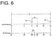
Fig. 6 , the positions of theend sensor 14 and theweft sensor 18 within the width TL of the cloth are shown above the line (a) and various timings within the width TL of the cloth are indicated on the line (b). As shown inFig. 6 , theweft sensor 18 may be disposed at a position that is shifted from the idealleading end position 2L corresponding to the third weft release timing B3 that is detected by theballoon sensor 10. In the embodiment of the present invention shown inFig. 6 , theweft sensor 18 is disposed at the position X that is spaced downstream from the idealleading end position 2L of the weft yarn Y by a distance α. Thus, the weft release distance from the storage drum 8 becomes 2L-α and the weft release timing BX at which the ideal leading end position of the weft yarn Y coincide with the position X of theweft sensor 18 may be estimated from the second weft release timing B2 and the third weft release timing B3. Thecontrol device 16 determines the travel condition of the weft yarn Y from the time difference Δ between the weft passage timing IS of the weft yarn Y and the weft release timing BX. In this case, the position of theweft sensor 18 is not limited to the ideal leading end positions L, 2L corresponding to the weft yarn release signal from theballoon sensor 10, so that theweft sensor 18 may be positioned more freely. - (2) In the first and second embodiments, the
weft insertion nozzle 2 may dispense with thetandem nozzle 11. - (3) Although the
weft sensor 18 is disposed at the idealleading end position 2L of the weft yarn Y that corresponds to the third weft release timing B3 immediately before the braking start timing BT in the first embodiment, theweft sensor 18 may be arranged at any ideal leading end position of the weft yarn Y that corresponds to nth weft release signal from theballoon sensor 10 generated immediately before the braking start timing BT. Merely by monitoring the time difference Δ between the weft passage timing IS of the weft yarn Y and the nth weft release signal from the balloon sensor 10 (weft release timing), the estimation of weft release timing is not required, so that the weft insertion device 1 is controlled more easily. - (4) The number of the weft sensors is not limited to one or two as described in the first and second embodiments, respectively. Any suitable number of the weft sensors may be disposed in the air jet loom. For example, the air jet loom may include three or more weft sensors. In any case, weft sensors are disposed upstream of the leading end position of the weft yarn to be located at the braking start timing BT with respect to the weft insertion direction so as to detect the weft yarn Y.
- (5) In the first embodiment, the
weft sensor 18 may be disposed at the ideal leading end position L and the difference between the weft passage timing IS and the second weft release timing B2 may be determined based on the angular position of the air jet loom. - There is provided a method for monitoring weft traveling condition in an air jet loom that includes a weft measuring and storing device having a drum, a weft stop pin, and a balloon sensor that detects the release of the weft yarn. The air jet loom further includes a weft insertion nozzle, a plurality of sub-nozzles, a brake, and a weft sensor that is disposed within a width of cloth. The weft sensor is disposed upstream of a position of leading end of the weft yarn corresponding to a brake timing of the brake in weft insertion direction. The weft traveling condition is monitored by grasping a time difference between a weft passage timing given by a weft detection signal generated by the weft sensor and a weft release timing given by a weft release signal generated by the balloon sensor.
Claims (3)
- A method for monitoring weft traveling condition in an air jet loom, wherein the air jet loom includes a weft measuring and storage device (4) that has a storage drum (8) storing a weft yarn (Y), a weft stop pin (9) releasing and stopping the weft yarn (Y), and a balloon sensor (10) detecting the release of the weft yarn (Y), wherein the air jet loom further includes a weft insertion nozzle (2), a plurality of sub-nozzles (7), a brake (13) that applies braking to the weft yarn (Y) before weft insertion ends, and a weft sensor (18) that is disposed near a weft traveling passage (6) within a width of cloth to be woven by the air jet loom so as to detect the weft yarn (Y), characterized by comprising:disposing the weft sensor (18) upstream of a leading end position (BL) of the weft yarn (Y) to be located at a braking start timing (BT) of the brake (13) with respect to a weft insertion direction; andgrasping a time difference between a weft passage timing (IS) given by a weft detection signal generated by the weft sensor (18) and a weft release timing (B3) given by a weft release signal generated by the balloon sensor (10) to monitor traveling condition of the weft yarn (Y), wherein the weft release timing (B3) is when the weft yarn (Y) is released from the storage drum (8) by a length that extends along the weft insertion direction from an end of the cloth closest to an upstream end of the weft traveling passage (6) with respect to the weft insertion direction to the weft sensor (18).
- The method according to claim 1, characterized by disposing the weft sensor (18) so as to detect one of a plurality of ideal leading end positions (L, 2L, 3L) of the weft yarn (Y) given by respective weft release signals generated by the balloon sensor (10), wherein the one ideal leading end position (3L) is closest to the leading end position (3L) of the weft yarn (Y) to be located at the braking start timing (BT) of the brake (13) of the ideal leading end positions (L, 2L, 3L).
- The method according to claim 1 or 2, characterized by disposing a weft sensor (50) near the weft traveling passage (6) within the width of the cloth and upstream of the leading end position (L, 2L) of the weft yarn (Y) to be located at the braking start timing (BT) with respect to the weft insertion direction so as to detect the weft yarn (Y).
Applications Claiming Priority (1)
| Application Number | Priority Date | Filing Date | Title |
|---|---|---|---|
| JP2015182415A JP6135731B2 (en) | 2015-09-16 | 2015-09-16 | Method of monitoring weft flying condition in air jet loom |
Publications (3)
| Publication Number | Publication Date |
|---|---|
| EP3144422A2 true EP3144422A2 (en) | 2017-03-22 |
| EP3144422A3 EP3144422A3 (en) | 2017-04-26 |
| EP3144422B1 EP3144422B1 (en) | 2018-10-17 |
Family
ID=56738017
Family Applications (1)
| Application Number | Title | Priority Date | Filing Date |
|---|---|---|---|
| EP16184668.8A Active EP3144422B1 (en) | 2015-09-16 | 2016-08-18 | Method for monitoring weft traveling condition in air jet loom |
Country Status (3)
| Country | Link |
|---|---|
| EP (1) | EP3144422B1 (en) |
| JP (1) | JP6135731B2 (en) |
| CN (1) | CN107034575B (en) |
Cited By (3)
| Publication number | Priority date | Publication date | Assignee | Title |
|---|---|---|---|---|
| EP3470562A1 (en) * | 2017-10-11 | 2019-04-17 | Tsudakoma Kogyo Kabushiki Kaisha | Method of setting weft travel information for air jet loom |
| EP3498900A1 (en) * | 2017-12-15 | 2019-06-19 | Tsudakoma Kogyo Kabushiki Kaisha | Method of setting weft travel information for air jet loom |
| CN114606627A (en) * | 2020-12-08 | 2022-06-10 | 株式会社丰田自动织机 | Weft insertion control device for air jet loom |
Families Citing this family (6)
| Publication number | Priority date | Publication date | Assignee | Title |
|---|---|---|---|---|
| JP6994377B2 (en) * | 2017-12-13 | 2022-01-14 | 株式会社豊田自動織機 | Weaving diagnostic method for air jet looms |
| JP7368075B2 (en) * | 2018-05-08 | 2023-10-24 | 株式会社豊田自動織機 | Weft insertion control method in air jet loom |
| CN109949435A (en) * | 2019-02-27 | 2019-06-28 | 深圳市海弘装备技术有限公司 | Intelligent unattended spinning and weaving workshop monitoring method and system |
| CN109629088B (en) * | 2019-02-27 | 2023-12-19 | 山东日发纺织机械有限公司 | Weft insertion device of air jet loom and automatic adjustment method thereof |
| WO2021024340A1 (en) | 2019-08-05 | 2021-02-11 | 大浩研熱株式会社 | Hydroponic tank and drainage part |
| JP2022062820A (en) * | 2020-10-09 | 2022-04-21 | 株式会社豊田自動織機 | Air-jet loom weft insertion device |
Citations (1)
| Publication number | Priority date | Publication date | Assignee | Title |
|---|---|---|---|---|
| JPH04240249A (en) | 1991-01-22 | 1992-08-27 | Nissan Motor Co Ltd | Weft-insertion controlling apparatus for air-jet loom |
Family Cites Families (14)
| Publication number | Priority date | Publication date | Assignee | Title |
|---|---|---|---|---|
| JPH0819604B2 (en) * | 1986-01-13 | 1996-02-28 | 津田駒工業株式会社 | Weft insertion self-diagnosis device for fluid jet loom |
| KR960005668Y1 (en) * | 1991-11-22 | 1996-07-11 | 닛산 텍시스 가부시끼가이샤 | Control system of weaving loom |
| JP3044897B2 (en) * | 1992-01-28 | 2000-05-22 | 株式会社豊田自動織機製作所 | Weft insertion method in jet loom |
| JPH0693534A (en) * | 1992-09-10 | 1994-04-05 | Toyota Autom Loom Works Ltd | Apparatus for controlling weft-insertion in jet loom |
| JP3121169B2 (en) * | 1993-03-25 | 2000-12-25 | 津田駒工業株式会社 | Weft braking device in jet loom |
| JP2605838Y2 (en) * | 1993-11-10 | 2000-08-21 | 株式会社豊田自動織機製作所 | Weaving weft insertion device |
| JP3669605B2 (en) * | 1997-05-09 | 2005-07-13 | 津田駒工業株式会社 | Sub nozzle injection control method |
| JP2001181945A (en) * | 1999-12-27 | 2001-07-03 | Tsudakoma Corp | Weft yarn sensor abnormality-detecting device |
| JP5216990B2 (en) * | 2005-11-21 | 2013-06-19 | ピカノール | Method of introducing weft yarn in an air jet loom and an air jet loom |
| DE502008002034D1 (en) * | 2007-02-02 | 2011-02-03 | Itema Switzerland Ltd | Method and device for introducing a weft thread into a loom |
| JP5550822B2 (en) * | 2008-09-09 | 2014-07-16 | 津田駒工業株式会社 | How to display the weft insertion status of the loom |
| BE1018762A3 (en) * | 2009-05-27 | 2011-08-02 | Picanol Nv | METHOD FOR INSERTING AN IMPRESSION THREAD AND AERIAL WEAVING MACHINE. |
| JP5423597B2 (en) * | 2010-06-28 | 2014-02-19 | 株式会社豊田自動織機 | Weft insertion state discrimination device and weft insertion control device in jet loom |
| JP2012224959A (en) * | 2011-04-20 | 2012-11-15 | Tsudakoma Corp | Method and apparatus for adjusting injection angle position of sub-nozzle in air injection type loom |
-
2015
- 2015-09-16 JP JP2015182415A patent/JP6135731B2/en active Active
-
2016
- 2016-08-18 EP EP16184668.8A patent/EP3144422B1/en active Active
- 2016-09-08 CN CN201610811539.4A patent/CN107034575B/en active Active
Patent Citations (1)
| Publication number | Priority date | Publication date | Assignee | Title |
|---|---|---|---|---|
| JPH04240249A (en) | 1991-01-22 | 1992-08-27 | Nissan Motor Co Ltd | Weft-insertion controlling apparatus for air-jet loom |
Cited By (4)
| Publication number | Priority date | Publication date | Assignee | Title |
|---|---|---|---|---|
| EP3470562A1 (en) * | 2017-10-11 | 2019-04-17 | Tsudakoma Kogyo Kabushiki Kaisha | Method of setting weft travel information for air jet loom |
| EP3498900A1 (en) * | 2017-12-15 | 2019-06-19 | Tsudakoma Kogyo Kabushiki Kaisha | Method of setting weft travel information for air jet loom |
| CN114606627A (en) * | 2020-12-08 | 2022-06-10 | 株式会社丰田自动织机 | Weft insertion control device for air jet loom |
| EP4019678A1 (en) * | 2020-12-08 | 2022-06-29 | Kabushiki Kaisha Toyota Jidoshokki | Air-jet loom with weft-insertion control apparatus |
Also Published As
| Publication number | Publication date |
|---|---|
| CN107034575A (en) | 2017-08-11 |
| CN107034575B (en) | 2018-09-07 |
| JP2017057516A (en) | 2017-03-23 |
| EP3144422A3 (en) | 2017-04-26 |
| EP3144422B1 (en) | 2018-10-17 |
| JP6135731B2 (en) | 2017-05-31 |
Similar Documents
| Publication | Publication Date | Title |
|---|---|---|
| EP3144422B1 (en) | Method for monitoring weft traveling condition in air jet loom | |
| EP3156529B1 (en) | Air jet loom with weft insertion control device | |
| JP2008190108A (en) | Method and apparatus for insertion of weft thread in weaving machine | |
| JP6190250B2 (en) | Weft detection device for air jet loom | |
| EP3323920B1 (en) | Weft traveling condition detection apparatus in air jet loom | |
| EP2643509A2 (en) | A method and apparatus for controlling a jet loom | |
| EP2230342A1 (en) | Storage device and method for storing weft threads in a loom | |
| JP6281475B2 (en) | Weft detection method in air jet loom | |
| US4781224A (en) | Loom equipped with weft picking control system | |
| KR930004535A (en) | Fluid jet looms and how to operate them | |
| EP3348688B1 (en) | Method for diagnosing weft insertion in air jet loom and apparatus for diagnosing weft insertion in air jet loom | |
| JP7099329B2 (en) | Warp and weft detector for air jet looms | |
| EP3498902B1 (en) | Method for diagnosing weft insertion in air-jet loom | |
| EP2765229B1 (en) | Air jet loom with a display device | |
| JP6954113B2 (en) | Reed runout detection method for air jet looms | |
| EP2732085B1 (en) | A loom with assigned yarn sensor and method for the operation thereof | |
| EP4019678B1 (en) | Air-jet loom with weft-insertion control apparatus | |
| EP1331294A2 (en) | Electric selvage device control method for fluid-jet loom | |
| JP2618376B2 (en) | Weft insertion method in jet room | |
| JP6447582B2 (en) | Weft detection method and weft detection device for air jet loom | |
| JP2021021166A (en) | Weft yarn defect determination device for looms | |
| JP2001234450A (en) | Method and apparatus for weft inserting of fluid jet type loom |
Legal Events
| Date | Code | Title | Description |
|---|---|---|---|
| PUAI | Public reference made under article 153(3) epc to a published international application that has entered the european phase |
Free format text: ORIGINAL CODE: 0009012 |
|
| STAA | Information on the status of an ep patent application or granted ep patent |
Free format text: STATUS: REQUEST FOR EXAMINATION WAS MADE |
|
| 17P | Request for examination filed |
Effective date: 20160818 |
|
| AK | Designated contracting states |
Kind code of ref document: A2 Designated state(s): AL AT BE BG CH CY CZ DE DK EE ES FI FR GB GR HR HU IE IS IT LI LT LU LV MC MK MT NL NO PL PT RO RS SE SI SK SM TR |
|
| AX | Request for extension of the european patent |
Extension state: BA ME |
|
| PUAL | Search report despatched |
Free format text: ORIGINAL CODE: 0009013 |
|
| AK | Designated contracting states |
Kind code of ref document: A3 Designated state(s): AL AT BE BG CH CY CZ DE DK EE ES FI FR GB GR HR HU IE IS IT LI LT LU LV MC MK MT NL NO PL PT RO RS SE SI SK SM TR |
|
| AX | Request for extension of the european patent |
Extension state: BA ME |
|
| RIC1 | Information provided on ipc code assigned before grant |
Ipc: D03D 47/34 20060101ALI20170322BHEP Ipc: D03D 47/30 20060101AFI20170322BHEP |
|
| GRAP | Despatch of communication of intention to grant a patent |
Free format text: ORIGINAL CODE: EPIDOSNIGR1 |
|
| STAA | Information on the status of an ep patent application or granted ep patent |
Free format text: STATUS: GRANT OF PATENT IS INTENDED |
|
| INTG | Intention to grant announced |
Effective date: 20180305 |
|
| GRAS | Grant fee paid |
Free format text: ORIGINAL CODE: EPIDOSNIGR3 |
|
| GRAA | (expected) grant |
Free format text: ORIGINAL CODE: 0009210 |
|
| STAA | Information on the status of an ep patent application or granted ep patent |
Free format text: STATUS: THE PATENT HAS BEEN GRANTED |
|
| AK | Designated contracting states |
Kind code of ref document: B1 Designated state(s): AL AT BE BG CH CY CZ DE DK EE ES FI FR GB GR HR HU IE IS IT LI LT LU LV MC MK MT NL NO PL PT RO RS SE SI SK SM TR |
|
| REG | Reference to a national code |
Ref country code: GB Ref legal event code: FG4D |
|
| REG | Reference to a national code |
Ref country code: CH Ref legal event code: EP |
|
| REG | Reference to a national code |
Ref country code: IE Ref legal event code: FG4D |
|
| REG | Reference to a national code |
Ref country code: DE Ref legal event code: R096 Ref document number: 602016006470 Country of ref document: DE Ref country code: AT Ref legal event code: REF Ref document number: 1054166 Country of ref document: AT Kind code of ref document: T Effective date: 20181115 |
|
| REG | Reference to a national code |
Ref country code: NL Ref legal event code: MP Effective date: 20181017 |
|
| REG | Reference to a national code |
Ref country code: LT Ref legal event code: MG4D |
|
| REG | Reference to a national code |
Ref country code: AT Ref legal event code: MK05 Ref document number: 1054166 Country of ref document: AT Kind code of ref document: T Effective date: 20181017 |
|
| PG25 | Lapsed in a contracting state [announced via postgrant information from national office to epo] |
Ref country code: NL Free format text: LAPSE BECAUSE OF FAILURE TO SUBMIT A TRANSLATION OF THE DESCRIPTION OR TO PAY THE FEE WITHIN THE PRESCRIBED TIME-LIMIT Effective date: 20181017 |
|
| PG25 | Lapsed in a contracting state [announced via postgrant information from national office to epo] |
Ref country code: IS Free format text: LAPSE BECAUSE OF FAILURE TO SUBMIT A TRANSLATION OF THE DESCRIPTION OR TO PAY THE FEE WITHIN THE PRESCRIBED TIME-LIMIT Effective date: 20190217 Ref country code: FI Free format text: LAPSE BECAUSE OF FAILURE TO SUBMIT A TRANSLATION OF THE DESCRIPTION OR TO PAY THE FEE WITHIN THE PRESCRIBED TIME-LIMIT Effective date: 20181017 Ref country code: LV Free format text: LAPSE BECAUSE OF FAILURE TO SUBMIT A TRANSLATION OF THE DESCRIPTION OR TO PAY THE FEE WITHIN THE PRESCRIBED TIME-LIMIT Effective date: 20181017 Ref country code: AT Free format text: LAPSE BECAUSE OF FAILURE TO SUBMIT A TRANSLATION OF THE DESCRIPTION OR TO PAY THE FEE WITHIN THE PRESCRIBED TIME-LIMIT Effective date: 20181017 Ref country code: NO Free format text: LAPSE BECAUSE OF FAILURE TO SUBMIT A TRANSLATION OF THE DESCRIPTION OR TO PAY THE FEE WITHIN THE PRESCRIBED TIME-LIMIT Effective date: 20190117 Ref country code: BG Free format text: LAPSE BECAUSE OF FAILURE TO SUBMIT A TRANSLATION OF THE DESCRIPTION OR TO PAY THE FEE WITHIN THE PRESCRIBED TIME-LIMIT Effective date: 20190117 Ref country code: HR Free format text: LAPSE BECAUSE OF FAILURE TO SUBMIT A TRANSLATION OF THE DESCRIPTION OR TO PAY THE FEE WITHIN THE PRESCRIBED TIME-LIMIT Effective date: 20181017 Ref country code: PL Free format text: LAPSE BECAUSE OF FAILURE TO SUBMIT A TRANSLATION OF THE DESCRIPTION OR TO PAY THE FEE WITHIN THE PRESCRIBED TIME-LIMIT Effective date: 20181017 Ref country code: LT Free format text: LAPSE BECAUSE OF FAILURE TO SUBMIT A TRANSLATION OF THE DESCRIPTION OR TO PAY THE FEE WITHIN THE PRESCRIBED TIME-LIMIT Effective date: 20181017 Ref country code: ES Free format text: LAPSE BECAUSE OF FAILURE TO SUBMIT A TRANSLATION OF THE DESCRIPTION OR TO PAY THE FEE WITHIN THE PRESCRIBED TIME-LIMIT Effective date: 20181017 |
|
| PG25 | Lapsed in a contracting state [announced via postgrant information from national office to epo] |
Ref country code: PT Free format text: LAPSE BECAUSE OF FAILURE TO SUBMIT A TRANSLATION OF THE DESCRIPTION OR TO PAY THE FEE WITHIN THE PRESCRIBED TIME-LIMIT Effective date: 20190217 Ref country code: AL Free format text: LAPSE BECAUSE OF FAILURE TO SUBMIT A TRANSLATION OF THE DESCRIPTION OR TO PAY THE FEE WITHIN THE PRESCRIBED TIME-LIMIT Effective date: 20181017 Ref country code: GR Free format text: LAPSE BECAUSE OF FAILURE TO SUBMIT A TRANSLATION OF THE DESCRIPTION OR TO PAY THE FEE WITHIN THE PRESCRIBED TIME-LIMIT Effective date: 20190118 Ref country code: SE Free format text: LAPSE BECAUSE OF FAILURE TO SUBMIT A TRANSLATION OF THE DESCRIPTION OR TO PAY THE FEE WITHIN THE PRESCRIBED TIME-LIMIT Effective date: 20181017 Ref country code: RS Free format text: LAPSE BECAUSE OF FAILURE TO SUBMIT A TRANSLATION OF THE DESCRIPTION OR TO PAY THE FEE WITHIN THE PRESCRIBED TIME-LIMIT Effective date: 20181017 |
|
| REG | Reference to a national code |
Ref country code: DE Ref legal event code: R097 Ref document number: 602016006470 Country of ref document: DE |
|
| PG25 | Lapsed in a contracting state [announced via postgrant information from national office to epo] |
Ref country code: CZ Free format text: LAPSE BECAUSE OF FAILURE TO SUBMIT A TRANSLATION OF THE DESCRIPTION OR TO PAY THE FEE WITHIN THE PRESCRIBED TIME-LIMIT Effective date: 20181017 Ref country code: DK Free format text: LAPSE BECAUSE OF FAILURE TO SUBMIT A TRANSLATION OF THE DESCRIPTION OR TO PAY THE FEE WITHIN THE PRESCRIBED TIME-LIMIT Effective date: 20181017 |
|
| PLBE | No opposition filed within time limit |
Free format text: ORIGINAL CODE: 0009261 |
|
| STAA | Information on the status of an ep patent application or granted ep patent |
Free format text: STATUS: NO OPPOSITION FILED WITHIN TIME LIMIT |
|
| PG25 | Lapsed in a contracting state [announced via postgrant information from national office to epo] |
Ref country code: EE Free format text: LAPSE BECAUSE OF FAILURE TO SUBMIT A TRANSLATION OF THE DESCRIPTION OR TO PAY THE FEE WITHIN THE PRESCRIBED TIME-LIMIT Effective date: 20181017 Ref country code: SM Free format text: LAPSE BECAUSE OF FAILURE TO SUBMIT A TRANSLATION OF THE DESCRIPTION OR TO PAY THE FEE WITHIN THE PRESCRIBED TIME-LIMIT Effective date: 20181017 Ref country code: SK Free format text: LAPSE BECAUSE OF FAILURE TO SUBMIT A TRANSLATION OF THE DESCRIPTION OR TO PAY THE FEE WITHIN THE PRESCRIBED TIME-LIMIT Effective date: 20181017 Ref country code: RO Free format text: LAPSE BECAUSE OF FAILURE TO SUBMIT A TRANSLATION OF THE DESCRIPTION OR TO PAY THE FEE WITHIN THE PRESCRIBED TIME-LIMIT Effective date: 20181017 |
|
| 26N | No opposition filed |
Effective date: 20190718 |
|
| PG25 | Lapsed in a contracting state [announced via postgrant information from national office to epo] |
Ref country code: SI Free format text: LAPSE BECAUSE OF FAILURE TO SUBMIT A TRANSLATION OF THE DESCRIPTION OR TO PAY THE FEE WITHIN THE PRESCRIBED TIME-LIMIT Effective date: 20181017 |
|
| PG25 | Lapsed in a contracting state [announced via postgrant information from national office to epo] |
Ref country code: TR Free format text: LAPSE BECAUSE OF FAILURE TO SUBMIT A TRANSLATION OF THE DESCRIPTION OR TO PAY THE FEE WITHIN THE PRESCRIBED TIME-LIMIT Effective date: 20181017 |
|
| PG25 | Lapsed in a contracting state [announced via postgrant information from national office to epo] |
Ref country code: LU Free format text: LAPSE BECAUSE OF NON-PAYMENT OF DUE FEES Effective date: 20190818 Ref country code: LI Free format text: LAPSE BECAUSE OF NON-PAYMENT OF DUE FEES Effective date: 20190831 Ref country code: CH Free format text: LAPSE BECAUSE OF NON-PAYMENT OF DUE FEES Effective date: 20190831 Ref country code: MC Free format text: LAPSE BECAUSE OF FAILURE TO SUBMIT A TRANSLATION OF THE DESCRIPTION OR TO PAY THE FEE WITHIN THE PRESCRIBED TIME-LIMIT Effective date: 20181017 |
|
| PG25 | Lapsed in a contracting state [announced via postgrant information from national office to epo] |
Ref country code: IE Free format text: LAPSE BECAUSE OF NON-PAYMENT OF DUE FEES Effective date: 20190818 Ref country code: FR Free format text: LAPSE BECAUSE OF NON-PAYMENT OF DUE FEES Effective date: 20190831 |
|
| GBPC | Gb: european patent ceased through non-payment of renewal fee |
Effective date: 20200818 |
|
| PG25 | Lapsed in a contracting state [announced via postgrant information from national office to epo] |
Ref country code: CY Free format text: LAPSE BECAUSE OF FAILURE TO SUBMIT A TRANSLATION OF THE DESCRIPTION OR TO PAY THE FEE WITHIN THE PRESCRIBED TIME-LIMIT Effective date: 20181017 |
|
| PG25 | Lapsed in a contracting state [announced via postgrant information from national office to epo] |
Ref country code: HU Free format text: LAPSE BECAUSE OF FAILURE TO SUBMIT A TRANSLATION OF THE DESCRIPTION OR TO PAY THE FEE WITHIN THE PRESCRIBED TIME-LIMIT; INVALID AB INITIO Effective date: 20160818 Ref country code: MT Free format text: LAPSE BECAUSE OF FAILURE TO SUBMIT A TRANSLATION OF THE DESCRIPTION OR TO PAY THE FEE WITHIN THE PRESCRIBED TIME-LIMIT Effective date: 20181017 |
|
| PG25 | Lapsed in a contracting state [announced via postgrant information from national office to epo] |
Ref country code: GB Free format text: LAPSE BECAUSE OF NON-PAYMENT OF DUE FEES Effective date: 20200818 |
|
| PG25 | Lapsed in a contracting state [announced via postgrant information from national office to epo] |
Ref country code: MK Free format text: LAPSE BECAUSE OF FAILURE TO SUBMIT A TRANSLATION OF THE DESCRIPTION OR TO PAY THE FEE WITHIN THE PRESCRIBED TIME-LIMIT Effective date: 20181017 |
|
| P01 | Opt-out of the competence of the unified patent court (upc) registered |
Effective date: 20230519 |
|
| PGFP | Annual fee paid to national office [announced via postgrant information from national office to epo] |
Ref country code: IT Payment date: 20230711 Year of fee payment: 8 |
|
| PGFP | Annual fee paid to national office [announced via postgrant information from national office to epo] |
Ref country code: DE Payment date: 20230627 Year of fee payment: 8 Ref country code: BE Payment date: 20230719 Year of fee payment: 8 |