EP3143328B1 - Système de génération d'effets lumineux à fonction d'ombrage - Google Patents
Système de génération d'effets lumineux à fonction d'ombrage Download PDFInfo
- Publication number
- EP3143328B1 EP3143328B1 EP15717117.4A EP15717117A EP3143328B1 EP 3143328 B1 EP3143328 B1 EP 3143328B1 EP 15717117 A EP15717117 A EP 15717117A EP 3143328 B1 EP3143328 B1 EP 3143328B1
- Authority
- EP
- European Patent Office
- Prior art keywords
- light
- surface structure
- darkening
- sheet
- arrangement according
- Prior art date
- Legal status (The legal status is an assumption and is not a legal conclusion. Google has not performed a legal analysis and makes no representation as to the accuracy of the status listed.)
- Active
Links
Images


Classifications
-
- F—MECHANICAL ENGINEERING; LIGHTING; HEATING; WEAPONS; BLASTING
- F21—LIGHTING
- F21V—FUNCTIONAL FEATURES OR DETAILS OF LIGHTING DEVICES OR SYSTEMS THEREOF; STRUCTURAL COMBINATIONS OF LIGHTING DEVICES WITH OTHER ARTICLES, NOT OTHERWISE PROVIDED FOR
- F21V1/00—Shades for light sources, i.e. lampshades for table, floor, wall or ceiling lamps
- F21V1/12—Composite shades, i.e. shades being made of distinct parts
-
- B—PERFORMING OPERATIONS; TRANSPORTING
- B32—LAYERED PRODUCTS
- B32B—LAYERED PRODUCTS, i.e. PRODUCTS BUILT-UP OF STRATA OF FLAT OR NON-FLAT, e.g. CELLULAR OR HONEYCOMB, FORM
- B32B5/00—Layered products characterised by the non- homogeneity or physical structure, i.e. comprising a fibrous, filamentary, particulate or foam layer; Layered products characterised by having a layer differing constitutionally or physically in different parts
- B32B5/22—Layered products characterised by the non- homogeneity or physical structure, i.e. comprising a fibrous, filamentary, particulate or foam layer; Layered products characterised by having a layer differing constitutionally or physically in different parts characterised by the presence of two or more layers which are next to each other and are fibrous, filamentary, formed of particles or foamed
- B32B5/24—Layered products characterised by the non- homogeneity or physical structure, i.e. comprising a fibrous, filamentary, particulate or foam layer; Layered products characterised by having a layer differing constitutionally or physically in different parts characterised by the presence of two or more layers which are next to each other and are fibrous, filamentary, formed of particles or foamed one layer being a fibrous or filamentary layer
- B32B5/26—Layered products characterised by the non- homogeneity or physical structure, i.e. comprising a fibrous, filamentary, particulate or foam layer; Layered products characterised by having a layer differing constitutionally or physically in different parts characterised by the presence of two or more layers which are next to each other and are fibrous, filamentary, formed of particles or foamed one layer being a fibrous or filamentary layer another layer next to it also being fibrous or filamentary
-
- F—MECHANICAL ENGINEERING; LIGHTING; HEATING; WEAPONS; BLASTING
- F21—LIGHTING
- F21V—FUNCTIONAL FEATURES OR DETAILS OF LIGHTING DEVICES OR SYSTEMS THEREOF; STRUCTURAL COMBINATIONS OF LIGHTING DEVICES WITH OTHER ARTICLES, NOT OTHERWISE PROVIDED FOR
- F21V11/00—Screens not covered by groups F21V1/00, F21V3/00, F21V7/00 or F21V9/00
- F21V11/08—Screens not covered by groups F21V1/00, F21V3/00, F21V7/00 or F21V9/00 using diaphragms containing one or more apertures
- F21V11/14—Screens not covered by groups F21V1/00, F21V3/00, F21V7/00 or F21V9/00 using diaphragms containing one or more apertures with many small apertures
-
- F—MECHANICAL ENGINEERING; LIGHTING; HEATING; WEAPONS; BLASTING
- F21—LIGHTING
- F21V—FUNCTIONAL FEATURES OR DETAILS OF LIGHTING DEVICES OR SYSTEMS THEREOF; STRUCTURAL COMBINATIONS OF LIGHTING DEVICES WITH OTHER ARTICLES, NOT OTHERWISE PROVIDED FOR
- F21V33/00—Structural combinations of lighting devices with other articles, not otherwise provided for
- F21V33/0004—Personal or domestic articles
- F21V33/0024—Household or table equipment
-
- F—MECHANICAL ENGINEERING; LIGHTING; HEATING; WEAPONS; BLASTING
- F21—LIGHTING
- F21V—FUNCTIONAL FEATURES OR DETAILS OF LIGHTING DEVICES OR SYSTEMS THEREOF; STRUCTURAL COMBINATIONS OF LIGHTING DEVICES WITH OTHER ARTICLES, NOT OTHERWISE PROVIDED FOR
- F21V33/00—Structural combinations of lighting devices with other articles, not otherwise provided for
- F21V33/006—General building constructions or finishing work for buildings, e.g. roofs, gutters, stairs or floors; Garden equipment; Sunshades or parasols
-
- F—MECHANICAL ENGINEERING; LIGHTING; HEATING; WEAPONS; BLASTING
- F21—LIGHTING
- F21V—FUNCTIONAL FEATURES OR DETAILS OF LIGHTING DEVICES OR SYSTEMS THEREOF; STRUCTURAL COMBINATIONS OF LIGHTING DEVICES WITH OTHER ARTICLES, NOT OTHERWISE PROVIDED FOR
- F21V11/00—Screens not covered by groups F21V1/00, F21V3/00, F21V7/00 or F21V9/00
- F21V11/16—Screens not covered by groups F21V1/00, F21V3/00, F21V7/00 or F21V9/00 using sheets without apertures, e.g. fixed
- F21V11/18—Screens not covered by groups F21V1/00, F21V3/00, F21V7/00 or F21V9/00 using sheets without apertures, e.g. fixed movable, e.g. flaps, slides
- F21V11/186—Screens not covered by groups F21V1/00, F21V3/00, F21V7/00 or F21V9/00 using sheets without apertures, e.g. fixed movable, e.g. flaps, slides slidable
-
- F—MECHANICAL ENGINEERING; LIGHTING; HEATING; WEAPONS; BLASTING
- F21—LIGHTING
- F21W—INDEXING SCHEME ASSOCIATED WITH SUBCLASSES F21K, F21L, F21S and F21V, RELATING TO USES OR APPLICATIONS OF LIGHTING DEVICES OR SYSTEMS
- F21W2121/00—Use or application of lighting devices or systems for decorative purposes, not provided for in codes F21W2102/00 – F21W2107/00
Definitions
- the invention relates to an arrangement for generating light effects.
- Such an arrangement is for example off WO 2011/015621 A1 known.
- the known arrangement comprises a light source and a fabric arranged away from the light source.
- This textile fabric is designed as a fabric and has a warp thread layer and a weft thread layer.
- the light emitted by the light source can be reflected or deflected at the warp threads or weft threads.
- On the side facing away from the light source side of the fabric thereby creates a light pattern that can produce a three-dimensional lighting effect for the viewer.
- Such arrangements are illuminated, for example, by means of light-emitting diodes or other light sources. They can be used for decorative purposes.
- EP 1 371 897 A1 describes a lit picture frame with a light panel as the backlight, a decorative image arranged above it and a filter.
- the arrangement has a plurality of webs arranged at least partially overlapping in the viewing direction of a viewer.
- the viewing direction is oriented substantially perpendicular to the plane of extent of the sheets.
- the assembly has a blackout sheet.
- the darkening sheet has a light incident side and a light emission side. The light incident side faces an artificial or natural light source.
- the darkening sheet has at least one passage area and at least one shielding area. The light incident on the shading sheet on the light incident side passes at least through the at least one passage area and exits from the passage area on the light exit side.
- the at least one shielding area can almost completely shield the light.
- the blackout sheet can meet the requirements of a so-called "black-out material". At least the intensity of the light emerging at the light exit side in the passband is greater than in the shielding region, so that a sufficient intensity difference of the light between the darker shielding region and the brighter passage region on the light exit side is ensured.
- the blackout sheet is formed by a black-out sheet, wherein the at least one through-band extends through recesses at least in the at least one blackout sheet of the blackout sheet is formed.
- the at least one passage region may have any shape or form.
- one or more passbands may form a logo, lettering, pattern, or the like. It can also be used for aesthetic interior design.
- the total area of the one or more passage areas is at least a factor of 10 smaller than the entire remaining area of the at least one shielding area.
- the arrangement also has an effect surface structure.
- the effect sheet is made of a textile material, preferably a fabric.
- the arrangement of the yarns or threads in the textile material the desired light effect can be effected.
- the effect sheet has a back side facing the darkening sheet and a back side opposite the back side. The light emerging from the passage areas of the darkening sheet strikes the back of the effect sheet and is reflected and / or scattered and / or broken and / or diffracted at the yarns. As a result, the light pattern or the light effect is produced in the viewing direction on the viewing side.
- the blackout sheet Due to the configuration of the arrangement according to the invention, it is possible on the light incidence side of the blackout sheet to arrange other than point or hemispherical light sources.
- the blackout area acts as a kind of aperture. It is thus possible to produce more complex light patterns or lettering with light effects.
- the natural light in particular sunlight, can also be used as the light source via the darkening surface.
- the arrangement includes a divergence sheet in addition to the darkening sheet and the effect sheet to convert the parallel sunlight into divergent light.
- hemispherically radiated and preferably approximately isotropic light can be generated at the at least one transmission region via the diverging surface structure.
- the divergence sheet and the blackout sheet form, as it were, one or more virtual dot-shaped light sources in the at least one passband.
- the arrangement is also suitable as a sunscreen or for shading and can therefore be used in sun blinds, umbrellas, blackout blinds or the like facilities.
- the intensity of the light passing through the at least one transmission region is at least 5 to 10 times, preferably 10 to 30 times, greater than the intensity of the light passing through the at least one shielding region.
- the divergence sheet is disposed between the blackout sheet and the effect sheet.
- the divergence sheet may also be part of the blackout sheet.
- the divergence sheet and the darkening surface are flat against each other and, for example, are bonded together in a material-locking manner.
- the divergent light-generating material of the diverging sheet is arranged very close to the at least one passage region.
- the handling of the arrangement is simplified when the divergence sheet and the darkening sheet are firmly bonded together.
- the divergent sheet may comprise a film and / or fibrous material and / or textile material.
- a fibrous or nonwoven material having sufficient fiber spacing may be used to diffuse the substantially parallel light.
- the blackout sheet and / or divergence sheet and / or effect sheet may each consist of one or more adjacent layers.
- a multilayer effect surface may be advantageous for achieving the desired light effects or light patterns.
- the blackout sheet has a backing layer which may be, for example, a sheet material and / or a fibrous material and / or a textile material.
- a backing layer which may be, for example, a sheet material and / or a fibrous material and / or a textile material.
- On this carrier layer is at least one darkening position arranged.
- one or more blackout layers can be arranged on both sides of the carrier layer.
- the at least one passage region may be formed by an aperture in the blackout sheet which eliminates all layers of the blackout sheet.
- the carrier layer can be retained in the passage region and only the darkening layers arranged thereon are left out.
- the carrier layer can serve as a divergence layer and thus for generating the divergent light.
- the carrier layer can thus be part of the divergence sheet or form the divergent sheet.
- the blackout sheet and / or the effect sheet is wound up and unwound on a respective winding shaft.
- the darkening sheet and / or the effect sheet can be made as a pleat and be pulled or pulled apart like an accordion. It is possible - as mentioned above - that the Divergenz vomgetrucke is firmly and extensively connected to the blackout sheet.
- the distance between the blackout sheet and the effect sheet or between the blackout sheet and the diverging sheet may be formed by an air gap and / or by a bonding layer.
- the connection layer consists, at least in the region in which the light propagates from the at least one passage region or the divergence surface to the rear side of the effect surface, for the used light wavelength or the wavelength range of light used transparent material.
- the connecting layer can be embodied, as far as is technically possible, opaque to light, at least at one or more edge regions.
- the connection layer can also connect the effect surface structure with the Divergenz vomgetrucke or the blackout sheet only locally to specify the distance.
- the darkening sheet and the effect sheet may together or in each case comprise a tension rod, which is displaceably guided in a guide device.
- This embodiment may be used, for example, when the blackout sheet and / or the effect sheet is made as a blind or pleated.
- the blackout sheet has two mutually displaceable blackout layers, each having at least one passage area and at least one shielding area.
- the passage areas and shielding areas are configured identically or contoured.
- a complete darkening can thus be achieved if the passage region of one darkening layer coincides with the shielding region of the other darkening layer.
- a maximum passage of light through the passbands can be achieved if the two passbands of the two blackout layers completely cover each other.
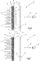
- Figures 1 and 2 is schematically illustrated in a second view of the multilayer structure of an embodiment of an arrangement 10 for generating light effects.
- the assembly 10 includes a blackout sheet 11, a divergent sheet 12, and an effect sheet 13.
- the darkening sheet 11 has a light incident side 15 and an opposite light exit side 16.
- At least one passage region 17 has at least one shielding region 18.
- the light L emitted from an artificial or natural light source and impinging on the light incident side 15 of the obscuration surface genome 11 passes through the obscurant sheet 11 at least through the at least one passage portion 17 and exits on the light exit side 16.
- the darkening surface structure 11 is configured in such a way that the intensity reduction of the light impinging on the light incidence side 15 in the at least one shielding region 18 is significantly greater and, for example, at least ten times greater than the intensity reduction of the light passing through the at least one transmissive region 17.
- the incident light L is almost completely shielded so that only a negligible proportion of light can pass through the shielding area 18.
- the shading sheet 11 is preferably constructed in the at least one shielding region 18 so as to satisfy the requirements for so-called "black-out" material.
- the at least one passage region 17 is formed by a respective recess 19 in the darkening surface 11, so that the light L there can pass unhindered from the light incident side 15 to the light exit side 16.
- a plurality of recesses 19 are provided in the form of cylindrical holes in the darkening sheet 11.
- the shape or contour of the recesses may be chosen differently from a circular cross-section also different.
- the total cross-sectional area of the recesses 19 is smaller and preferably smaller by at least a factor of 10 than the entire area of the shielding area 18 surrounding the recesses 19.
- the distance D between two immediately adjacent recesses 19 be in a spatial direction in which the darkening sheet 11 extends is larger and preferably at least twice as large as the dimension of the recess 19 in this spatial direction.
- the blackout sheet 11 In the embodiment of the blackout sheet 11 according to FIG. 1 only a single darkening 11a is provided. In contrast, the embodiments of the shading sheets 11 are as shown in FIG Figures 2 and 3 executed with multiple blackout layers 11a.
- the blackout sheet 11 has a carrier sheet 11b. On this carrier layer 11b is applied to one and, for example, on both sides in each case at least one darkening 11a.
- the carrier layer may preferably be a textile material, such as a fabric or a knit fabric.
- One or more darkening layers 11a are then applied to the carrier layer 11b on one or both sides.
- the darkening layers 11a are preferably made of a plastic material. The number and the thickness of the darkening layers are selected so as to achieve the required shielding effect for the incident light L required in the shielding region 18.
- FIG. 2 illustrates apertures are introduced into the blackout sheet 11, which completely pass through all the layers 11a, 11b. This can be done by cutting, for example, laser cutting, punching, or other suitable separation process.
- the recesses 19 are formed in the applied darkening layers 11a (FIG. FIG. 3 ).
- the recesses 19 are only present in the blackout layers 11a and do not enforce the carrier layer 11b.
- the recesses 19 are arranged in the darkening layers 11b at least substantially in alignment in a viewing direction B.
- the viewing direction B is oriented at right angles to the plane of extent in which the blackout sheet 11 extends.
- the carrier layer 11b may be part of the divergence sheet 12 or form this in this embodiment. The function of the diverging sheet 12 will be explained below.
- the divergence sheet 12 serves to diffuse parallel light L and to generate in the region of the light exit side 16 at the at least one passage region 17 divergent light beams LD. If the passage regions 17 or recesses 19 are sufficiently small in cross-section, then a virtual punctiform light source is produced on the light exit side 16 at each recess 19 in combination with the diverging surfaces 12, emitting hemispherical divergent light beams LD preferably isotropically technically possible.
- the divergence sheet 12 may be a film and / or a textile material and / or a fiber material and be embodied, for example, as a woven fabric, knitted fabric, nonwoven fabric or cellulose.
- the diverging sheet 12 is flat and fixed to the blackout sheet 11. It can for example be arranged directly on the light exit side 16 of the darkening surface 11 ( FIG. 1 ) or alternatively be integrated as a layer in the darkening sheet 11.
- the divergence sheet 12 may be formed by the backing sheet 11b and may be coated with a blackout sheet 11a from one or both sides.
- the darkening sheet 11 thus has the function of a kind of aperture and generates at the at least one passage area 17 together with the divergence sheet 12 the divergent light beams LD.
- the divergent light beams LD strike the effect surface formation 13, which is arranged at a distance A from the divergence surface formation 12.
- the effect sheet 13 has a back side 23, which faces the divergence sheet 12 and the light exit side 16 of the darkening sheet 11, respectively.
- the divergent light beams LD strike this rear side 23.
- the effect surface structure 13 has a viewing side 24.
- the viewing side 24 faces an observer 25.
- the effect surface structure 13 preferably comprises a textile material and / or a fiber material and / or a foil material.
- the effect sheet 13 may be made of one or more yarns, in the embodiment as a fabric.
- the divergent light beams LD impinge on the back side 23 and are at least partially scattered and / or reflected and / or refracted by the effect surface fabric and, for example, at respective yarn sections.
- a predetermined, desired lighting effect for the viewer 25 can be generated.
- a three-dimensional light effect 26 can arise.
- star-shaped beams can be generated around the virtual light sources at the recesses 19, which for the viewer 25 also extend from the plane of the effect surface structure 13 backwards into the room. Ellipse or line patterns can also be generated.
- the inventive arrangement 10 can work with any natural or artificial light sources.
- the sunlight striking the earth is parallel, so that no light effect could be generated by the effect surface structure 13.
- the arrangement 10 generates the divergent light beams LD from the parallel light L and can thus generate a light effect 26 even in sunlight.
- the assembly 10 is therefore suitable for use with sun protection or shading devices, such as parasols, sun sails, roller blinds or the like. For example, when darkening a room during the day, a special lighting effect can still be created on the darkened windows.
- the divergence sheet 12 may also be eliminated.
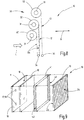
- FIGS. 4 and 5 schematically two embodiments of a structural design of the arrangement 10 are illustrated.
- the arrangement 10 is designed in the form of a double roller blind 30.
- the darkening sheet 11 and the divergence sheet 12 are directly adjacent to each other wound on a common winding shaft 31 of a first shade 32.
- the effect surface structure 13 is wound on a winding shaft 31 of a second roller blind 33.
- the two blinds 32, 33 may be coupled together, so that when turning a winding shaft 31 of a blinds 32 or 33 and the winding shaft 31 of the other blinds 33 and 32 respectively rotates. This can be achieved, for example, in that the fabrics 11, 12, 13 are connected at their respective free end to a common tie rod 34.
- the winding shafts 31 of the two blinds 32, 33 can also be coupled to one another via a coupling means, for example a gear, a belt or the like.
- a coupling means for example a gear, a belt or the like.
- a connection of the effect surface structure 13 with the other Flaähhenformen 11, 12 omitted.
- the arrangement of the blinds 32, 33 is such that the distance A is set between the effect surface structure 13 and the divergence surface 12.
- FIG. 5 is a further constructive embodiment of the arrangement 10 illustrated.
- no blinds 32, 33, but pleats 35, 36 are provided.
- a first pleat 35 is present for the obscurant sheet 11 and the divergent sheet 12, while the second pleat 36 for the effect sheet 13 is present.
- the fabrics 11, 12 can be folded accordion-like and pulled apart.
- the sheets 12, 13 are substantially fully stretched when the respective sheet 11, 12, 13 is completely pulled apart.
- Each pleat 35, 36 may have a tension rod 34, which is connected to the respective free end of the respective associated sheet 11, 12 and 13 respectively.
- the pull rod 34 may be guided guided guide means 37. It is also possible in this case to couple the two tension rods 34 with one another or to design them as a common component, so that the operation of the pleats 35, 36 is coupled.
- the darkening surface 11 has two darkening layers 11a which can be displaced relative to one another in relation to the viewing direction B.
- each darkening layer 11a has at least one passage region 17 and one shielding region 18, which are preferably contoured or designed identically.
- the passage regions 17 can be shifted toward one another in coincidence or in such a way that the passage region 17 of one darkening layer 11a coincides with the screening region 18 of the other darkening layer 11 (FIG. FIG. 7 ).
- the arrangement 10 can be used for complete shading or darkening. If the passage regions 17, that is to say the recesses 19, for example, at least partly overlap the two darkening layers 11a, a light effect 26 can be produced ( FIG. 6 ).
- This embodiment can be realized by a roller blind arrangement 30 ( FIG. 8 ).
- a third blind 40 may be present.
- On the third roller blind 40 a darkening layer 11a is wound, while on the first roller blind 32, the respective other darkening layer 11a is wound.
- One of the two darkening layers 11a may be as in FIG. 8 illustrated connected to the divergence sheet 12.
- the two darkening layers 11a may be associated with a common tension rod 34, and separate tension rods 34 may be provided for each roller blind 32, 40. Otherwise, the roller blind arrangement 30 corresponds to FIG FIG. 8 the roller blind assembly 30 from FIG. 4 so that reference may be made to the above description.
- the distance A between the effect surface structure 13 and the darkening surface 11 or the optional divergence surface 12 is formed by an air gap.
- the connection layer 41 may, for example, for those of the Be made light source L originating light wavelength or the light wavelength range transparent material.
- the bonding layer 41 is transparent to all light wavelengths of visible light.
- FIG. 9 schematically illustrates that one or more peripheral areas, such as the visible light edge surfaces 42, are rendered opaque or at least substantially impermeable. Thereby, an intrusion of stray light into the area between the effect sheet 13 and the divergence sheet 12 or the darkening sheet 11 can be reduced or prevented.
- roller blind assembly 30 or on the pleat assembly 35, 36 can be used to prevent the ingress of interfering light in this area.
- Such means may be arranged, for example, on a guide device for guiding a tension rod 34 of a roller blind or a plisse.
- the fabrics 11, 12, 13 in displaceable and / or pivotable Be held in a frame.
- the darkening sheet 11 may also be formed by a conventional sipe roller blind, wherein the slot openings present there represent the passage areas 17.
- the desired effect surface structure 13 can be introduced by a roller blind, pleated or the like on the window to produce a desired light effect 26.
- the Divergenzvidgesente 12 may consist of several individual strips which are glued to the slot openings in the shutter.
- the diverging sheet 12 consists of several parts, each part being associated with a passage area 17.
- the parts may be directly connected to each other or separately connected to the blackout sheet 11 so that there is only an indirect connection between the parts.
- the invention relates to an arrangement 10 for generating a light effect 26 on a viewing side 24 of an effect surface structure 13.
- a darkening sheet 11 and preferably a divergence sheet 12 is arranged at a distance from the rear side 23 facing away from the viewing side 24.
- the darkening sheet 11 has at least one passage area 17 and at least one shielding area 18.
- L strikes the darkening surface 11 and is at least greatly reduced or completely shielded in the at least one shielding region 18.
- the light L can pass through the at least one passage region 17.
- divergent light beams LD are generated at the respective passband 17, which impinge on the back 23 of the effect surface structure 13 and produce a light effect 26 for a viewer 25 with a view of the viewing side 24.
Landscapes
- Engineering & Computer Science (AREA)
- General Engineering & Computer Science (AREA)
- Architecture (AREA)
- Civil Engineering (AREA)
- Structural Engineering (AREA)
- Blinds (AREA)
- Laminated Bodies (AREA)
- Illuminated Signs And Luminous Advertising (AREA)
- Curtains And Furnishings For Windows Or Doors (AREA)
- Operating, Guiding And Securing Of Roll- Type Closing Members (AREA)
- Non-Portable Lighting Devices Or Systems Thereof (AREA)
- Treatment Of Fiber Materials (AREA)
Claims (13)
- Système (10) de génération d'un effet lumineux (26),
comprenant plusieurs structures planes (11, 12, 13) disposées de manière à se chevaucher au moins partiellement dans une direction d'observation (B),
comprenant une structure plane d'obscurcissement (11) qui présente une face d'incidence de lumière (15) et une face de sortie de lumière (16), et qui comporte au moins une zone de passage (17) et au moins une zone formant écran (18), sachant que la lumière (L) qui arrive sur la face d'incidence de lumière (15) traverse au moins la zone de passage (17), au nombre d'au moins une, et sort sur la face de sortie de lumière (16),
la diminution d'intensité de la lumière (L) arrivant sur la face d'incidence de lumière (15), dans la zone formant écran (18), au nombre d'au moins une, étant plus grande que la diminution d'intensité de la lumière (L) arrivant sur la zone de passage (17), au nombre d'au moins une,
comprenant au moins une structure plane d'effet (13) faite d'une matière textile qui présente une face arrière (23), tournée vers la face de sortie de lumière (16) de la structure plane d'obscurcissement (11), et une face d'observation (24), la structure plane d'effet (13) étant disposée à distance de la structure plane d'obscurcissement (11), et la lumière qui arrive sur la face arrière (23) étant au moins en partie réfléchie et/ou dispersée et/ou diffractée et/ou réfractée, et sortant au moins en partie sur la face d'observation (24),
comprenant une structure plane de divergence (12) qui est conçue pour transformer la lumière (L) incidente, sensiblement parallèle, en lumière divergente (LD),
caractérisé en ce que
la structure plane de divergence (11) présente un matériau en feuille et/ou un matériau en fibres et/ou une matière textile. - Système selon la revendication 1, caractérisé en ce que la zone de passage (17), au nombre d'au moins une, est formée par un évidement (19) dans la structure plane d'obscurcissement (11).
- Système selon la revendication 1 ou 2, caractérisé en ce que la zone formant écran (18), au nombre d'au moins une, bloque sensiblement complètement la lumière incidente.
- Système selon l'une des revendications précédentes, caractérisé en ce que l'intensité de la lumière traversant la zone de passage (17), au nombre d'au moins une, est supérieure d'au moins 5 à 10 fois ou de 10 à 30 fois à l'intensité de la lumière traversant la zone formant écran (18), au nombre d'au moins une.
- Système selon l'une des revendications précédentes, caractérisé en ce que la structure plane de divergence (12) est disposée entre la structure plane d'obscurcissement (11) et la structure plane d'effet (13).
- Système selon l'une des revendications précédentes, caractérisé en ce que la structure plane de divergence (12) et la structure plane d'obscurcissement (11) sont appliquées l'une contre l'autre.
- Système selon l'une des revendications précédentes, caractérisé en ce que la structure plane d'obscurcissement (11) constituée de plusieurs couches (11a, 11b) appliquées à plat les unes contre les autres.
- Système selon la revendication 7, caractérisé en ce que la structure plane d'obscurcissement (11) présente une couche de support (11b) sur laquelle est disposée au moins une couche d'obscurcissement (11a).
- Système selon la revendication 8, caractérisé en ce que la couche de support (11b) ne s'étend que dans la zone formant écran (18), au nombre d'au moins une, et laisse dégagée la zone de passage (17), au nombre d'au moins une.
- Système selon la revendication 8, caractérisé en ce que la couche de support (11b) s'étend dans la zone de passage (17), au nombre d'au moins une, et constitue au moins une couche de la structure plane de divergence (12).
- Système selon l'une des revendications précédentes, caractérisé en ce que la structure plane d'obscurcissement (11) et/ou la structure plane d'effet (13) peuvent être enroulées et déroulées respectivement sur un arbre d'enroulement (31) et/ou sont pliées avec possibilité de repliage et de dépliage.
- Système selon la revendication 11, caractérisé en ce que la structure plane d'obscurcissement (11) et/ou la structure plane d'effet (13) présentent respectivement une barre de traction (34) qui est guidée de manière coulissante respectivement dans un dispositif de guidage (37).
- Système selon l'une des revendications précédentes, caractérisé en ce que la structure plane d'obscurcissement (11) présente deux couches d'obscurcissement (11a) qui peuvent être déplacées l'une par rapport à l'autre et qui comportent chacune au moins une zone de passage (17) et au moins une zone formant écran (18).
Applications Claiming Priority (2)
| Application Number | Priority Date | Filing Date | Title |
|---|---|---|---|
| DE102014106602.2A DE102014106602A1 (de) | 2014-05-12 | 2014-05-12 | Anordnung zur Erzeugung von Lichteffekten mit Beschattungsfunktion |
| PCT/EP2015/057460 WO2015172941A1 (fr) | 2014-05-12 | 2015-04-07 | Système de génération d'effets lumineux à fonction d'ombrage |
Publications (2)
| Publication Number | Publication Date |
|---|---|
| EP3143328A1 EP3143328A1 (fr) | 2017-03-22 |
| EP3143328B1 true EP3143328B1 (fr) | 2019-06-12 |
Family
ID=52988023
Family Applications (1)
| Application Number | Title | Priority Date | Filing Date |
|---|---|---|---|
| EP15717117.4A Active EP3143328B1 (fr) | 2014-05-12 | 2015-04-07 | Système de génération d'effets lumineux à fonction d'ombrage |
Country Status (8)
| Country | Link |
|---|---|
| US (1) | US10443809B2 (fr) |
| EP (1) | EP3143328B1 (fr) |
| JP (1) | JP6708628B2 (fr) |
| KR (1) | KR102372447B1 (fr) |
| CN (1) | CN106461194B (fr) |
| DE (1) | DE102014106602A1 (fr) |
| TR (1) | TR201909753T4 (fr) |
| WO (1) | WO2015172941A1 (fr) |
Families Citing this family (7)
| Publication number | Priority date | Publication date | Assignee | Title |
|---|---|---|---|---|
| DE102016202016A1 (de) * | 2016-02-10 | 2017-08-10 | Bos Gmbh & Co. Kg | Beschattungssystem für einen Fahrzeuginnenraum |
| DE102016107636A1 (de) * | 2016-04-25 | 2017-11-23 | Gebr. Achter GmbH & Co. KG | Leuchtinstallation |
| DE102017215369A1 (de) * | 2017-09-01 | 2019-03-07 | Benecke-Kaliko Ag | Lichtdurchlässige Mehrschichtverbundfolie |
| DE102018131135A1 (de) * | 2018-11-05 | 2020-05-07 | Neutex Home Deco Gmbh | Gewebe, insbesondere zur Verwendung als Sicht- und/oder Blendschutz, und Verfahren zur Herstellung eines erfindungsgemäßen Gewebes |
| US20240093857A1 (en) * | 2019-10-18 | 2024-03-21 | Hunter Douglas Inc. | Lighted architectural-structure covering |
| DE102021116099A1 (de) * | 2020-11-02 | 2022-05-05 | Olsa S.P.A. | Optische vorrichtung für kraftfahrzeuge, lampe für kraftfahrzeuge und umgebungslicht |
| CN113048413B (zh) * | 2021-03-24 | 2022-08-05 | 上海莹通照明工程有限公司 | 一种便于调节光照范围的照明装置 |
Family Cites Families (16)
| Publication number | Priority date | Publication date | Assignee | Title |
|---|---|---|---|---|
| US3961434A (en) * | 1974-11-18 | 1976-06-08 | Everbrite Electric Signs, Inc. | Animated sign |
| US4263737A (en) * | 1980-04-04 | 1981-04-28 | Thomas A. Schutz Co., Inc. | Illuminated grid display with primary and secondary copy |
| NL9300014A (nl) * | 1993-01-06 | 1994-08-01 | Ass Marinus T J Van | Lichtdoorlatend scherm, gebouw voorzien van een lichtdoorlatend scherm en werkwijze voor het afschermen van een ruimte. |
| US5772314A (en) * | 1995-09-15 | 1998-06-30 | Brumer; Daryl J. | Ceiling ornament system |
| DE19946015A1 (de) * | 1999-09-25 | 2001-04-19 | Bayerische Motoren Werke Ag | Vorrichtung zum Dimmen einer Lampe |
| FR2840972A1 (fr) * | 2002-06-12 | 2003-12-19 | Marc Fontoynont | Dispositif d'eclairage et de decoration |
| DE20300615U1 (de) * | 2003-01-15 | 2003-03-27 | Wild Franz | Lampenschirm |
| JP2005242244A (ja) * | 2004-02-27 | 2005-09-08 | Shin Nippon Process Kogeisha:Kk | ディスプレー装置 |
| KR200398864Y1 (ko) * | 2005-07-25 | 2005-10-17 | (주)한국윈텍 | 다중롤유닛을 이용한 멀티블라인드장치 |
| KR20090018865A (ko) * | 2006-06-08 | 2009-02-23 | 코닌클리즈케 필립스 일렉트로닉스 엔.브이. | 직물 제품, 직물 제품 제조 방법, 및 유연한 발광 디스플레이 |
| WO2007144816A2 (fr) * | 2006-06-12 | 2007-12-21 | Koninklijke Philips Electronics N.V. | Procédé et système d'éclairage |
| ATE528423T1 (de) | 2009-08-05 | 2011-10-15 | Ettlin Spinnerei Und Weberei Produktions Gmbh & Co Kg | Anordnung zur erzeugung von lichteffekten |
| KR101260120B1 (ko) * | 2010-12-09 | 2013-05-02 | (주)엘지하우시스 | 이미지를 구현할 수 있는 표면소재를 구비한 표시 장치 및 그 제조방법 |
| JP2012174634A (ja) * | 2011-02-24 | 2012-09-10 | Sharp Corp | 光源モジュールおよび光学部材 |
| US10132470B2 (en) * | 2011-09-05 | 2018-11-20 | Robe Lighting S.R.O. | Versatile beam and wash optical system for an automated luminaire |
| DE102012215165B4 (de) * | 2012-08-27 | 2020-12-03 | Lisa Dräxlmaier GmbH | Dekorverbund mit dynamischen Lichtstrukturen |
-
2014
- 2014-05-12 DE DE102014106602.2A patent/DE102014106602A1/de not_active Ceased
-
2015
- 2015-04-07 CN CN201580024787.8A patent/CN106461194B/zh active Active
- 2015-04-07 KR KR1020167033878A patent/KR102372447B1/ko active IP Right Grant
- 2015-04-07 US US15/310,619 patent/US10443809B2/en active Active
- 2015-04-07 EP EP15717117.4A patent/EP3143328B1/fr active Active
- 2015-04-07 JP JP2017512104A patent/JP6708628B2/ja active Active
- 2015-04-07 WO PCT/EP2015/057460 patent/WO2015172941A1/fr active Application Filing
- 2015-04-07 TR TR2019/09753T patent/TR201909753T4/tr unknown
Non-Patent Citations (1)
| Title |
|---|
| None * |
Also Published As
| Publication number | Publication date |
|---|---|
| WO2015172941A1 (fr) | 2015-11-19 |
| JP6708628B2 (ja) | 2020-06-10 |
| TR201909753T4 (tr) | 2019-07-22 |
| US20170082259A1 (en) | 2017-03-23 |
| US10443809B2 (en) | 2019-10-15 |
| EP3143328A1 (fr) | 2017-03-22 |
| DE102014106602A1 (de) | 2015-11-12 |
| CN106461194B (zh) | 2020-02-14 |
| KR102372447B1 (ko) | 2022-03-10 |
| JP2017518448A (ja) | 2017-07-06 |
| KR20170008247A (ko) | 2017-01-23 |
| CN106461194A (zh) | 2017-02-22 |
Similar Documents
| Publication | Publication Date | Title |
|---|---|---|
| EP3143328B1 (fr) | Système de génération d'effets lumineux à fonction d'ombrage | |
| EP2284306B1 (fr) | Agencement destiné à la production d'effets lumineux | |
| WO2012113603A1 (fr) | Dispositif d'éclairage | |
| DE19922973A1 (de) | Lichtdurchlässige Scheibenanordnung | |
| DE102010031192B4 (de) | Lentikular-Leuchtvorrichtung und Bedienelement | |
| DE102013020715B4 (de) | Gleichmäßig leuchtendes Textilgewebe | |
| EP2576879B1 (fr) | Système d'occultation | |
| EP3058123B1 (fr) | Système pour guider de la lumière | |
| EP0524388B1 (fr) | Dispositif d'éclairage naturel | |
| EP2587134B1 (fr) | Eclairage | |
| DE102009007198A1 (de) | Fahrzeug mit Armaturenbrett und Anzeigevorrichtung für das Armaturenbrett sowie ein Verfahren zur Herstellung der Anzeigevorrichtung | |
| WO1987000012A1 (fr) | Procede d'obtention d'effets luminescents sur des matieres textiles | |
| DE102013100292A1 (de) | Beleuchtung zur Detektion von Regentropfen auf einer Scheibe mittels einer Kamera | |
| WO2020104352A1 (fr) | Procédé de fabrication d'une sangle pour un système de ceinture de sécurité dans un véhicule, sangle et véhicule équipé de la sangle | |
| EP3239602B1 (fr) | Installation d'éclairage | |
| DE4336763A1 (de) | Vorrichtung zur Vermeidung der direkten Einstrahlung von Sonnenstrahlen und dergleichen Lichtquellen durch Fenster | |
| EP4355971A1 (fr) | Dispositif de protection visuelle | |
| EP0001636B1 (fr) | Dispositif d'exposition, utilisable dans un appareil d'agrandissement ou de tirage en couleurs | |
| DE3524734C2 (fr) | ||
| DE546254C (de) | Trommelverschluss | |
| DE102019103580A1 (de) | Leuchtvorrichtung sowie innenraumverkleidung oder verkleidungselement mit einer leuchtvorrichtung | |
| DE102018208740A1 (de) | Verfahren zur Erzeugung einer Innenraumbeleuchtung im Bereich eines Dachausschnitts eines Kraftfahrzeugs sowie Abschattungsanordnung zur Durchführung des Verfahrens | |
| DE2511574A1 (de) | Projektionswand | |
| DE10324852A1 (de) | Tageslichtbeleuchtungssystem | |
| DE202013101772U1 (de) | Leuchte zur Erzeugung einer Direktbeleuchtung und einer Indirekt-Beleuchtung |
Legal Events
| Date | Code | Title | Description |
|---|---|---|---|
| STAA | Information on the status of an ep patent application or granted ep patent |
Free format text: STATUS: THE INTERNATIONAL PUBLICATION HAS BEEN MADE |
|
| PUAI | Public reference made under article 153(3) epc to a published international application that has entered the european phase |
Free format text: ORIGINAL CODE: 0009012 |
|
| STAA | Information on the status of an ep patent application or granted ep patent |
Free format text: STATUS: REQUEST FOR EXAMINATION WAS MADE |
|
| 17P | Request for examination filed |
Effective date: 20161102 |
|
| AK | Designated contracting states |
Kind code of ref document: A1 Designated state(s): AL AT BE BG CH CY CZ DE DK EE ES FI FR GB GR HR HU IE IS IT LI LT LU LV MC MK MT NL NO PL PT RO RS SE SI SK SM TR |
|
| AX | Request for extension of the european patent |
Extension state: BA ME |
|
| DAV | Request for validation of the european patent (deleted) | ||
| DAX | Request for extension of the european patent (deleted) | ||
| GRAP | Despatch of communication of intention to grant a patent |
Free format text: ORIGINAL CODE: EPIDOSNIGR1 |
|
| STAA | Information on the status of an ep patent application or granted ep patent |
Free format text: STATUS: GRANT OF PATENT IS INTENDED |
|
| INTG | Intention to grant announced |
Effective date: 20190122 |
|
| GRAS | Grant fee paid |
Free format text: ORIGINAL CODE: EPIDOSNIGR3 |
|
| GRAA | (expected) grant |
Free format text: ORIGINAL CODE: 0009210 |
|
| STAA | Information on the status of an ep patent application or granted ep patent |
Free format text: STATUS: THE PATENT HAS BEEN GRANTED |
|
| AK | Designated contracting states |
Kind code of ref document: B1 Designated state(s): AL AT BE BG CH CY CZ DE DK EE ES FI FR GB GR HR HU IE IS IT LI LT LU LV MC MK MT NL NO PL PT RO RS SE SI SK SM TR |
|
| REG | Reference to a national code |
Ref country code: GB Ref legal event code: FG4D Free format text: NOT ENGLISH |
|
| REG | Reference to a national code |
Ref country code: CH Ref legal event code: EP |
|
| REG | Reference to a national code |
Ref country code: AT Ref legal event code: REF Ref document number: 1143026 Country of ref document: AT Kind code of ref document: T Effective date: 20190615 |
|
| REG | Reference to a national code |
Ref country code: CH Ref legal event code: NV Representative=s name: VALIPAT S.A. C/O BOVARD SA NEUCHATEL, CH |
|
| REG | Reference to a national code |
Ref country code: DE Ref legal event code: R096 Ref document number: 502015009315 Country of ref document: DE |
|
| REG | Reference to a national code |
Ref country code: IE Ref legal event code: FG4D Free format text: LANGUAGE OF EP DOCUMENT: GERMAN |
|
| REG | Reference to a national code |
Ref country code: NL Ref legal event code: MP Effective date: 20190612 |
|
| REG | Reference to a national code |
Ref country code: LT Ref legal event code: MG4D |
|
| PG25 | Lapsed in a contracting state [announced via postgrant information from national office to epo] |
Ref country code: LT Free format text: LAPSE BECAUSE OF FAILURE TO SUBMIT A TRANSLATION OF THE DESCRIPTION OR TO PAY THE FEE WITHIN THE PRESCRIBED TIME-LIMIT Effective date: 20190612 Ref country code: FI Free format text: LAPSE BECAUSE OF FAILURE TO SUBMIT A TRANSLATION OF THE DESCRIPTION OR TO PAY THE FEE WITHIN THE PRESCRIBED TIME-LIMIT Effective date: 20190612 Ref country code: NO Free format text: LAPSE BECAUSE OF FAILURE TO SUBMIT A TRANSLATION OF THE DESCRIPTION OR TO PAY THE FEE WITHIN THE PRESCRIBED TIME-LIMIT Effective date: 20190912 Ref country code: SE Free format text: LAPSE BECAUSE OF FAILURE TO SUBMIT A TRANSLATION OF THE DESCRIPTION OR TO PAY THE FEE WITHIN THE PRESCRIBED TIME-LIMIT Effective date: 20190612 Ref country code: HR Free format text: LAPSE BECAUSE OF FAILURE TO SUBMIT A TRANSLATION OF THE DESCRIPTION OR TO PAY THE FEE WITHIN THE PRESCRIBED TIME-LIMIT Effective date: 20190612 Ref country code: AL Free format text: LAPSE BECAUSE OF FAILURE TO SUBMIT A TRANSLATION OF THE DESCRIPTION OR TO PAY THE FEE WITHIN THE PRESCRIBED TIME-LIMIT Effective date: 20190612 |
|
| PG25 | Lapsed in a contracting state [announced via postgrant information from national office to epo] |
Ref country code: BG Free format text: LAPSE BECAUSE OF FAILURE TO SUBMIT A TRANSLATION OF THE DESCRIPTION OR TO PAY THE FEE WITHIN THE PRESCRIBED TIME-LIMIT Effective date: 20190912 Ref country code: GR Free format text: LAPSE BECAUSE OF FAILURE TO SUBMIT A TRANSLATION OF THE DESCRIPTION OR TO PAY THE FEE WITHIN THE PRESCRIBED TIME-LIMIT Effective date: 20190913 Ref country code: RS Free format text: LAPSE BECAUSE OF FAILURE TO SUBMIT A TRANSLATION OF THE DESCRIPTION OR TO PAY THE FEE WITHIN THE PRESCRIBED TIME-LIMIT Effective date: 20190612 Ref country code: LV Free format text: LAPSE BECAUSE OF FAILURE TO SUBMIT A TRANSLATION OF THE DESCRIPTION OR TO PAY THE FEE WITHIN THE PRESCRIBED TIME-LIMIT Effective date: 20190612 |
|
| PG25 | Lapsed in a contracting state [announced via postgrant information from national office to epo] |
Ref country code: EE Free format text: LAPSE BECAUSE OF FAILURE TO SUBMIT A TRANSLATION OF THE DESCRIPTION OR TO PAY THE FEE WITHIN THE PRESCRIBED TIME-LIMIT Effective date: 20190612 Ref country code: SK Free format text: LAPSE BECAUSE OF FAILURE TO SUBMIT A TRANSLATION OF THE DESCRIPTION OR TO PAY THE FEE WITHIN THE PRESCRIBED TIME-LIMIT Effective date: 20190612 Ref country code: PT Free format text: LAPSE BECAUSE OF FAILURE TO SUBMIT A TRANSLATION OF THE DESCRIPTION OR TO PAY THE FEE WITHIN THE PRESCRIBED TIME-LIMIT Effective date: 20191014 Ref country code: CZ Free format text: LAPSE BECAUSE OF FAILURE TO SUBMIT A TRANSLATION OF THE DESCRIPTION OR TO PAY THE FEE WITHIN THE PRESCRIBED TIME-LIMIT Effective date: 20190612 Ref country code: NL Free format text: LAPSE BECAUSE OF FAILURE TO SUBMIT A TRANSLATION OF THE DESCRIPTION OR TO PAY THE FEE WITHIN THE PRESCRIBED TIME-LIMIT Effective date: 20190612 Ref country code: RO Free format text: LAPSE BECAUSE OF FAILURE TO SUBMIT A TRANSLATION OF THE DESCRIPTION OR TO PAY THE FEE WITHIN THE PRESCRIBED TIME-LIMIT Effective date: 20190612 |
|
| PG25 | Lapsed in a contracting state [announced via postgrant information from national office to epo] |
Ref country code: ES Free format text: LAPSE BECAUSE OF FAILURE TO SUBMIT A TRANSLATION OF THE DESCRIPTION OR TO PAY THE FEE WITHIN THE PRESCRIBED TIME-LIMIT Effective date: 20190612 Ref country code: IT Free format text: LAPSE BECAUSE OF FAILURE TO SUBMIT A TRANSLATION OF THE DESCRIPTION OR TO PAY THE FEE WITHIN THE PRESCRIBED TIME-LIMIT Effective date: 20190612 Ref country code: IS Free format text: LAPSE BECAUSE OF FAILURE TO SUBMIT A TRANSLATION OF THE DESCRIPTION OR TO PAY THE FEE WITHIN THE PRESCRIBED TIME-LIMIT Effective date: 20191012 Ref country code: SM Free format text: LAPSE BECAUSE OF FAILURE TO SUBMIT A TRANSLATION OF THE DESCRIPTION OR TO PAY THE FEE WITHIN THE PRESCRIBED TIME-LIMIT Effective date: 20190612 |
|
| REG | Reference to a national code |
Ref country code: DE Ref legal event code: R097 Ref document number: 502015009315 Country of ref document: DE |
|
| PLBE | No opposition filed within time limit |
Free format text: ORIGINAL CODE: 0009261 |
|
| STAA | Information on the status of an ep patent application or granted ep patent |
Free format text: STATUS: NO OPPOSITION FILED WITHIN TIME LIMIT |
|
| PG25 | Lapsed in a contracting state [announced via postgrant information from national office to epo] |
Ref country code: DK Free format text: LAPSE BECAUSE OF FAILURE TO SUBMIT A TRANSLATION OF THE DESCRIPTION OR TO PAY THE FEE WITHIN THE PRESCRIBED TIME-LIMIT Effective date: 20190612 Ref country code: PL Free format text: LAPSE BECAUSE OF FAILURE TO SUBMIT A TRANSLATION OF THE DESCRIPTION OR TO PAY THE FEE WITHIN THE PRESCRIBED TIME-LIMIT Effective date: 20190612 |
|
| 26N | No opposition filed |
Effective date: 20200313 |
|
| PG25 | Lapsed in a contracting state [announced via postgrant information from national office to epo] |
Ref country code: IS Free format text: LAPSE BECAUSE OF FAILURE TO SUBMIT A TRANSLATION OF THE DESCRIPTION OR TO PAY THE FEE WITHIN THE PRESCRIBED TIME-LIMIT Effective date: 20200224 Ref country code: SI Free format text: LAPSE BECAUSE OF FAILURE TO SUBMIT A TRANSLATION OF THE DESCRIPTION OR TO PAY THE FEE WITHIN THE PRESCRIBED TIME-LIMIT Effective date: 20190612 |
|
| PG2D | Information on lapse in contracting state deleted |
Ref country code: IS |
|
| PG25 | Lapsed in a contracting state [announced via postgrant information from national office to epo] |
Ref country code: MC Free format text: LAPSE BECAUSE OF FAILURE TO SUBMIT A TRANSLATION OF THE DESCRIPTION OR TO PAY THE FEE WITHIN THE PRESCRIBED TIME-LIMIT Effective date: 20190612 |
|
| PG25 | Lapsed in a contracting state [announced via postgrant information from national office to epo] |
Ref country code: LU Free format text: LAPSE BECAUSE OF NON-PAYMENT OF DUE FEES Effective date: 20200407 |
|
| REG | Reference to a national code |
Ref country code: BE Ref legal event code: MM Effective date: 20200430 |
|
| PG25 | Lapsed in a contracting state [announced via postgrant information from national office to epo] |
Ref country code: BE Free format text: LAPSE BECAUSE OF NON-PAYMENT OF DUE FEES Effective date: 20200430 |
|
| PG25 | Lapsed in a contracting state [announced via postgrant information from national office to epo] |
Ref country code: IE Free format text: LAPSE BECAUSE OF NON-PAYMENT OF DUE FEES Effective date: 20200407 |
|
| REG | Reference to a national code |
Ref country code: AT Ref legal event code: MM01 Ref document number: 1143026 Country of ref document: AT Kind code of ref document: T Effective date: 20200407 |
|
| PG25 | Lapsed in a contracting state [announced via postgrant information from national office to epo] |
Ref country code: AT Free format text: LAPSE BECAUSE OF NON-PAYMENT OF DUE FEES Effective date: 20200407 |
|
| PG25 | Lapsed in a contracting state [announced via postgrant information from national office to epo] |
Ref country code: MT Free format text: LAPSE BECAUSE OF FAILURE TO SUBMIT A TRANSLATION OF THE DESCRIPTION OR TO PAY THE FEE WITHIN THE PRESCRIBED TIME-LIMIT Effective date: 20190612 Ref country code: CY Free format text: LAPSE BECAUSE OF FAILURE TO SUBMIT A TRANSLATION OF THE DESCRIPTION OR TO PAY THE FEE WITHIN THE PRESCRIBED TIME-LIMIT Effective date: 20190612 |
|
| PG25 | Lapsed in a contracting state [announced via postgrant information from national office to epo] |
Ref country code: MK Free format text: LAPSE BECAUSE OF FAILURE TO SUBMIT A TRANSLATION OF THE DESCRIPTION OR TO PAY THE FEE WITHIN THE PRESCRIBED TIME-LIMIT Effective date: 20190612 |
|
| PGFP | Annual fee paid to national office [announced via postgrant information from national office to epo] |
Ref country code: FR Payment date: 20230426 Year of fee payment: 9 Ref country code: DE Payment date: 20230425 Year of fee payment: 9 Ref country code: CH Payment date: 20230602 Year of fee payment: 9 |
|
| PGFP | Annual fee paid to national office [announced via postgrant information from national office to epo] |
Ref country code: TR Payment date: 20230404 Year of fee payment: 9 |
|
| PGFP | Annual fee paid to national office [announced via postgrant information from national office to epo] |
Ref country code: GB Payment date: 20230428 Year of fee payment: 9 |