EP3142353A1 - Drohne mit frontal ausgerichteter kamera, deren kontrollparameter, insbesondere die automatische belichtung, unabhängig von der höhe konzipiert sind - Google Patents
Drohne mit frontal ausgerichteter kamera, deren kontrollparameter, insbesondere die automatische belichtung, unabhängig von der höhe konzipiert sind Download PDFInfo
- Publication number
- EP3142353A1 EP3142353A1 EP16188012.5A EP16188012A EP3142353A1 EP 3142353 A1 EP3142353 A1 EP 3142353A1 EP 16188012 A EP16188012 A EP 16188012A EP 3142353 A1 EP3142353 A1 EP 3142353A1
- Authority
- EP
- European Patent Office
- Prior art keywords
- drone
- image
- roi
- capture
- attitude
- Prior art date
- Legal status (The legal status is an assumption and is not a legal conclusion. Google has not performed a legal analysis and makes no representation as to the accuracy of the status listed.)
- Granted
Links
- 238000004458 analytical method Methods 0.000 claims description 40
- 230000007547 defect Effects 0.000 description 8
- 238000000034 method Methods 0.000 description 7
- 230000010355 oscillation Effects 0.000 description 6
- 238000000605 extraction Methods 0.000 description 5
- 230000006641 stabilisation Effects 0.000 description 5
- 238000011105 stabilization Methods 0.000 description 5
- 238000013519 translation Methods 0.000 description 5
- 238000006073 displacement reaction Methods 0.000 description 4
- 238000012545 processing Methods 0.000 description 4
- 239000002689 soil Substances 0.000 description 4
- 235000021183 entrée Nutrition 0.000 description 3
- 238000010191 image analysis Methods 0.000 description 3
- 208000031968 Cadaver Diseases 0.000 description 2
- XQCFHQBGMWUEMY-ZPUQHVIOSA-N Nitrovin Chemical compound C=1C=C([N+]([O-])=O)OC=1\C=C\C(=NNC(=N)N)\C=C\C1=CC=C([N+]([O-])=O)O1 XQCFHQBGMWUEMY-ZPUQHVIOSA-N 0.000 description 2
- 241000287531 Psittacidae Species 0.000 description 2
- 230000001133 acceleration Effects 0.000 description 2
- 230000009471 action Effects 0.000 description 2
- 238000004364 calculation method Methods 0.000 description 2
- 238000012937 correction Methods 0.000 description 2
- 238000007405 data analysis Methods 0.000 description 2
- 238000011161 development Methods 0.000 description 2
- 230000018109 developmental process Effects 0.000 description 2
- 238000010586 diagram Methods 0.000 description 2
- 238000012986 modification Methods 0.000 description 2
- 230000004048 modification Effects 0.000 description 2
- 238000011084 recovery Methods 0.000 description 2
- 238000005096 rolling process Methods 0.000 description 2
- 230000004913 activation Effects 0.000 description 1
- 230000002457 bidirectional effect Effects 0.000 description 1
- 230000005540 biological transmission Effects 0.000 description 1
- 230000003592 biomimetic effect Effects 0.000 description 1
- 230000008859 change Effects 0.000 description 1
- 238000004737 colorimetric analysis Methods 0.000 description 1
- 238000013461 design Methods 0.000 description 1
- 230000000694 effects Effects 0.000 description 1
- 230000008030 elimination Effects 0.000 description 1
- 238000003379 elimination reaction Methods 0.000 description 1
- 239000000284 extract Substances 0.000 description 1
- 238000005259 measurement Methods 0.000 description 1
- 239000003607 modifier Substances 0.000 description 1
- 230000008569 process Effects 0.000 description 1
- 238000005070 sampling Methods 0.000 description 1
- 230000035945 sensitivity Effects 0.000 description 1
- 230000007704 transition Effects 0.000 description 1
- XLYOFNOQVPJJNP-UHFFFAOYSA-N water Substances O XLYOFNOQVPJJNP-UHFFFAOYSA-N 0.000 description 1
Images


Classifications
-
- G—PHYSICS
- G05—CONTROLLING; REGULATING
- G05D—SYSTEMS FOR CONTROLLING OR REGULATING NON-ELECTRIC VARIABLES
- G05D1/00—Control of position, course, altitude or attitude of land, water, air or space vehicles, e.g. using automatic pilots
- G05D1/0011—Control of position, course, altitude or attitude of land, water, air or space vehicles, e.g. using automatic pilots associated with a remote control arrangement
- G05D1/0038—Control of position, course, altitude or attitude of land, water, air or space vehicles, e.g. using automatic pilots associated with a remote control arrangement by providing the operator with simple or augmented images from one or more cameras located onboard the vehicle, e.g. tele-operation
-
- H—ELECTRICITY
- H04—ELECTRIC COMMUNICATION TECHNIQUE
- H04N—PICTORIAL COMMUNICATION, e.g. TELEVISION
- H04N23/00—Cameras or camera modules comprising electronic image sensors; Control thereof
- H04N23/50—Constructional details
-
- B—PERFORMING OPERATIONS; TRANSPORTING
- B64—AIRCRAFT; AVIATION; COSMONAUTICS
- B64C—AEROPLANES; HELICOPTERS
- B64C39/00—Aircraft not otherwise provided for
- B64C39/02—Aircraft not otherwise provided for characterised by special use
- B64C39/024—Aircraft not otherwise provided for characterised by special use of the remote controlled vehicle type, i.e. RPV
-
- B—PERFORMING OPERATIONS; TRANSPORTING
- B64—AIRCRAFT; AVIATION; COSMONAUTICS
- B64D—EQUIPMENT FOR FITTING IN OR TO AIRCRAFT; FLIGHT SUITS; PARACHUTES; ARRANGEMENT OR MOUNTING OF POWER PLANTS OR PROPULSION TRANSMISSIONS IN AIRCRAFT
- B64D47/00—Equipment not otherwise provided for
- B64D47/08—Arrangements of cameras
-
- G—PHYSICS
- G05—CONTROLLING; REGULATING
- G05D—SYSTEMS FOR CONTROLLING OR REGULATING NON-ELECTRIC VARIABLES
- G05D1/00—Control of position, course, altitude or attitude of land, water, air or space vehicles, e.g. using automatic pilots
- G05D1/0094—Control of position, course, altitude or attitude of land, water, air or space vehicles, e.g. using automatic pilots involving pointing a payload, e.g. camera, weapon, sensor, towards a fixed or moving target
-
- G—PHYSICS
- G06—COMPUTING; CALCULATING OR COUNTING
- G06T—IMAGE DATA PROCESSING OR GENERATION, IN GENERAL
- G06T5/00—Image enhancement or restoration
- G06T5/80—Geometric correction
-
- G—PHYSICS
- G06—COMPUTING; CALCULATING OR COUNTING
- G06T—IMAGE DATA PROCESSING OR GENERATION, IN GENERAL
- G06T7/00—Image analysis
- G06T7/10—Segmentation; Edge detection
- G06T7/11—Region-based segmentation
-
- H—ELECTRICITY
- H04—ELECTRIC COMMUNICATION TECHNIQUE
- H04N—PICTORIAL COMMUNICATION, e.g. TELEVISION
- H04N23/00—Cameras or camera modules comprising electronic image sensors; Control thereof
- H04N23/50—Constructional details
- H04N23/55—Optical parts specially adapted for electronic image sensors; Mounting thereof
-
- H—ELECTRICITY
- H04—ELECTRIC COMMUNICATION TECHNIQUE
- H04N—PICTORIAL COMMUNICATION, e.g. TELEVISION
- H04N23/00—Cameras or camera modules comprising electronic image sensors; Control thereof
- H04N23/60—Control of cameras or camera modules
- H04N23/66—Remote control of cameras or camera parts, e.g. by remote control devices
- H04N23/661—Transmitting camera control signals through networks, e.g. control via the Internet
-
- H—ELECTRICITY
- H04—ELECTRIC COMMUNICATION TECHNIQUE
- H04N—PICTORIAL COMMUNICATION, e.g. TELEVISION
- H04N23/00—Cameras or camera modules comprising electronic image sensors; Control thereof
- H04N23/60—Control of cameras or camera modules
- H04N23/67—Focus control based on electronic image sensor signals
-
- H—ELECTRICITY
- H04—ELECTRIC COMMUNICATION TECHNIQUE
- H04N—PICTORIAL COMMUNICATION, e.g. TELEVISION
- H04N23/00—Cameras or camera modules comprising electronic image sensors; Control thereof
- H04N23/60—Control of cameras or camera modules
- H04N23/68—Control of cameras or camera modules for stable pick-up of the scene, e.g. compensating for camera body vibrations
-
- H—ELECTRICITY
- H04—ELECTRIC COMMUNICATION TECHNIQUE
- H04N—PICTORIAL COMMUNICATION, e.g. TELEVISION
- H04N23/00—Cameras or camera modules comprising electronic image sensors; Control thereof
- H04N23/60—Control of cameras or camera modules
- H04N23/698—Control of cameras or camera modules for achieving an enlarged field of view, e.g. panoramic image capture
-
- H—ELECTRICITY
- H04—ELECTRIC COMMUNICATION TECHNIQUE
- H04N—PICTORIAL COMMUNICATION, e.g. TELEVISION
- H04N23/00—Cameras or camera modules comprising electronic image sensors; Control thereof
- H04N23/70—Circuitry for compensating brightness variation in the scene
-
- H—ELECTRICITY
- H04—ELECTRIC COMMUNICATION TECHNIQUE
- H04N—PICTORIAL COMMUNICATION, e.g. TELEVISION
- H04N23/00—Cameras or camera modules comprising electronic image sensors; Control thereof
- H04N23/70—Circuitry for compensating brightness variation in the scene
- H04N23/71—Circuitry for evaluating the brightness variation
-
- H—ELECTRICITY
- H04—ELECTRIC COMMUNICATION TECHNIQUE
- H04N—PICTORIAL COMMUNICATION, e.g. TELEVISION
- H04N23/00—Cameras or camera modules comprising electronic image sensors; Control thereof
- H04N23/80—Camera processing pipelines; Components thereof
- H04N23/84—Camera processing pipelines; Components thereof for processing colour signals
- H04N23/88—Camera processing pipelines; Components thereof for processing colour signals for colour balance, e.g. white-balance circuits or colour temperature control
-
- H—ELECTRICITY
- H04—ELECTRIC COMMUNICATION TECHNIQUE
- H04N—PICTORIAL COMMUNICATION, e.g. TELEVISION
- H04N7/00—Television systems
- H04N7/18—Closed-circuit television [CCTV] systems, i.e. systems in which the video signal is not broadcast
- H04N7/183—Closed-circuit television [CCTV] systems, i.e. systems in which the video signal is not broadcast for receiving images from a single remote source
- H04N7/185—Closed-circuit television [CCTV] systems, i.e. systems in which the video signal is not broadcast for receiving images from a single remote source from a mobile camera, e.g. for remote control
-
- H—ELECTRICITY
- H04—ELECTRIC COMMUNICATION TECHNIQUE
- H04N—PICTORIAL COMMUNICATION, e.g. TELEVISION
- H04N9/00—Details of colour television systems
- H04N9/64—Circuits for processing colour signals
- H04N9/73—Colour balance circuits, e.g. white balance circuits or colour temperature control
-
- B—PERFORMING OPERATIONS; TRANSPORTING
- B64—AIRCRAFT; AVIATION; COSMONAUTICS
- B64U—UNMANNED AERIAL VEHICLES [UAV]; EQUIPMENT THEREFOR
- B64U10/00—Type of UAV
- B64U10/10—Rotorcrafts
- B64U10/13—Flying platforms
- B64U10/14—Flying platforms with four distinct rotor axes, e.g. quadcopters
-
- B—PERFORMING OPERATIONS; TRANSPORTING
- B64—AIRCRAFT; AVIATION; COSMONAUTICS
- B64U—UNMANNED AERIAL VEHICLES [UAV]; EQUIPMENT THEREFOR
- B64U2101/00—UAVs specially adapted for particular uses or applications
- B64U2101/30—UAVs specially adapted for particular uses or applications for imaging, photography or videography
Definitions
- the invention relates to the processing of digital images captured by an onboard camera in a remotely controlled mobile device, hereinafter "drone”, in particular in a motorized flying vehicle such as a flying drone or UAV ( Unmanned Aerial Vehicle ).
- drone a remotely controlled mobile device
- UAV Unmanned Aerial Vehicle
- the invention is however not limited to images collected by flying apparatus; it applies as well to rolling devices operating on the ground under the control of a distant operator, or floating devices operating on a body of water, the term "drone" to be understood in its most General.
- the invention is advantageously applied to the images collected by the front camera of a rotary wing drone such as a quadrocopter.
- the AR.Drone 2.0 or the Bebop Drone of Parrot SA, Paris, France are typical examples of such quadricopters. They are equipped with a series of sensors (accelerometers, 3-axis gyrometers, altimeters), a frontal camera capturing an image of the scene towards which the drone is directed and a vertical aiming camera capturing an image of the terrain overflown. . They are provided with multiple rotors driven by respective engines controllable in a differentiated manner to control the drone attitude and speed. Various aspects of these drones are described in particular in the WO 2010/061099 A2 , EP 2 364 757 A1 , EP 2 613 213 A1 or EP 2 613 214 A1 (Parrot SA).
- the front-facing video camera is usable for "immersive" control, ie where the user uses the camera image in the same way as if he were himself on board of the drone. It can also be used to capture sequences of images of a scene towards which the drone is heading. The user can thus use the drone in the same way as a camera or a camcorder that, instead of being held by hand, would be carried by the drone. Collected images can be recorded and broadcast, uploaded to sequence hosting websites video, sent to other Internet users, shared on social networks, etc.
- Bebop Drone implements a camera equipped with a fisheye type hemispherical field lens covering a field of about 180 °, but only part of the captured field is used, this corresponding part approximately to the angular sector captured by a conventional camera.
- a particular window (hereinafter “capture area”) is selected in the overall hemispherical image formed on the surface of the sensor.
- This window is mobile in rotation and in translation, and permanently moved according to the movements of the drone determined by the inertial unit, and in the opposite direction of these movements.
- the image collected by the fisheye lens certainly undergoes the same movements of oscillation and rotation as a conventional camera, but the displacement of the image zone is enslaved so as to compensate these movements and thus produce a stabilized image at the same time. respect of the movements of the drone.
- the image of the capture zone more exactly a useful part (hereinafter "gross useful area") thereof is then subjected to reprojection processing to compensate for the geometric distortions introduced by the fisheye lens. : straightening of straight lines bent by the lens, restoration of a uniform magnification between the center and the periphery image, etc.
- the final image obtained (“rectified pay zone") is then transmitted to the user for on-screen viewing, recording, etc.
- a “virtual camera” is thus defined by extracting from the captured total scene a particular zone (the capture zone) which is dynamically displaced, in rotation and in translation, in the initial image in the opposite direction to the movements of the drone in order to annihilate the oscillations that would otherwise be observed on the final image presented to the user, then applying an image rectification process to deliver a representation of the scene devoid of geometric distortions and the like.
- This technique is described in the application EP 2,933,775 A1 (Parrot), published on 21.10.2015 .
- the present invention aims at the elimination of a particular defect which appears during certain evolutions of the drone.
- This defect concerns the dynamic control of a certain number of operating parameters of the camera, namely parameters which are automatically adjusted by image analysis algorithms such as self-exposure algorithms (AE, based on a analysis of the brightness of the different points of the image), automatic white balance (AWB, based on a colorimetric analysis of the different points of the image) or automatic focusing (AF, based on a contrast analysis different points of the image).
- image analysis algorithms such as self-exposure algorithms (AE, based on a analysis of the brightness of the different points of the image), automatic white balance (AWB, based on a colorimetric analysis of the different points of the image) or automatic focusing (AF, based on a contrast analysis different points of the image).
- AE and AWB algorithms can be found in the US 2015/0222816 A1 , and AF algorithm in the US 2013/0021520 A1 .
- the automatic exposure control will be taken as a particular case, but the invention is not limited to the control of this parameter and, as will be understood, can be applied to the automatic control of the exposure.
- AE self-exposure algorithm
- this capture area is larger than the final useful area that will be presented to the user, so that the self-exposure algorithm can make decisions based on elements of the scene that the user does not see, that is to say elements located inside the capture zone but outside the useful area.
- the scene that is to be well exposed is that which is seen by the user (the useful area), and not the capture area, which differs from the latter.
- the proportion between sky and ground will vary according to the inclination of the camera, and therefore according to the attitude of the drone.
- the drone moves from an attitude of hovering to an inclined, plunging attitude (tilting linked to a linear displacement towards the front), then the camera, lowered towards the ground (because it is linked to the body of the drone ) will capture a good proportion more important soil.
- the ground is darker, servoing the self-exposure algorithm will tend to compensate for this variation in brightness by an increase in exposure time and / or gain.
- the user will always see the same scene. But this scene will be temporarily overexposed due to the corrective action of self-exposure, overexposure that will disappear when the drone returns to its initial attitude - and without the contours of the image seen by the user has changed .
- the shooting parameter retains a value that is substantially independent of the instantaneous variations of attitude of the drone.
- the analysis means are furthermore able to exclude from said image data contained in the image coming from the capture zone the raw image data which are located outside the region of the image formed by the image. objective on the sensor.
- the compensating means receive as input the image data included in the image coming from the capture zone, delivered by the extracting means, and the analysis means comprise means capable of dynamically defining in each image a plurality of regions of interest ROI distributed in the capture area with a corresponding thumbnail for each ROI, and outputting a current value of said shooting parameter for each respective thumbnail.
- the compensating means then comprise means capable of dynamically interacting with the analysis means by modifying the dimension and / or the positioning of the ROIs in the capture zone as a function of the current attitude data of the drone.
- the compensating means comprise means able to precede from the definition of the ROI those ROIs which are located outside the current user zone included in the capture zone.
- the compensating means may in particular comprise means capable of attributing to each ROI a weighting value that is a function of the greater or lesser extent of the recovery of the ROI with the current user zone defined inside the capture zone. this value being maximum for ROIs fully included in the current user area and less for overlapping ROIs extending both inside and outside the current user area.
- the compensating means may also comprise means capable of attributing to each ROI a weighting value that is a function of the greater or lesser area of the ROI.
- the compensating means receive as input the image data included in the image coming from the capture zone, delivered by the extractor means, and the analysis means comprise means able to define a grid ROI regions of interest uniformly and predeterminedly distributed in the capture area with a corresponding thumbnail for each ROI, and outputting a current value of said shooting parameter for each respective thumbnail.
- the compensating means then comprise means able to interact dynamically with the analysis means by allocating to each ROI a weighting value that is a function of the extent of overlap of the ROI with the current user area defined within the capture area, this value being maximum for ROIs included in the current user area, minimum for ROIs outside the current user area, and intermediate for overlapping ROIs extending both inside and out. outside the current user area.
- the compensating means receive as input the rectified image data, compensated for the geometrical distortions introduced by the fisheye lens , delivered by the reprojection means.
- the analysis means may in particular comprise means able to define dynamically in each image a plurality of regions of interest ROI distributed in the rectified image with a corresponding thumbnail for each ROI, and to deliver a current value of said shooting setting for each respective thumbnail.
- the compensating means then comprise means able to interact dynamically with the analysis means by modifying the dimension and / or the positioning of the ROI in the rectified image as a function of the current attitude data of the drone.
- the reference 10 generally designates a drone, which is for example a quadricopter such as the Bebop Drone model of Parrot SA, Paris, France.
- This drone comprises four coplanar rotors 12 whose engines are controlled independently by an integrated navigation system and attitude control. It is provided with a front-facing camera 14 for obtaining an image of the scene towards which the drone is oriented.
- the drone also includes a vertical aiming camera (not shown) pointing downwards, capable of capturing successive images of the terrain overflown and used in particular to evaluate the speed of the drone relative to the ground.
- Inertial sensors accelerelerometers and gyrometers
- Inertial sensors make it possible to measure with a certain accuracy the angular velocities and the angles of attitude of the drone, that is to say the angles of Euler (pitch ⁇ , roll ⁇ and yaw ⁇ ) describing the inclination of the drone with respect to a horizontal plane of a fixed terrestrial reference.
- An ultrasonic range finder disposed under the drone also provides a measurement of the altitude relative to the ground.
- the drone 10 is controlled by a remote remote control device 16 provided with a touch screen 18 displaying the image embedded by the front camera 14, with a number of symbols superimposed enabling the activation of control commands by simple contact of the
- the device 16 is provided with radio link means with the drone, for example of the Wi-Fi local network type (IEEE 802.11), for the bidirectional exchange of data of the device. drone 10 to the apparatus 16, in particular for transmitting the image picked up by the camera 14, and the apparatus 16 to the drone 10 for sending pilot commands.
- IEEE 802.11 Wi-Fi local network type
- the commands a) and b) pivoting about the pitch axes 22 and the rolling axis 24 are obtained by inclinations of the apparatus 16 respectively about its longitudinal axis 28 and its transverse axis 30: for example, to advance the drone simply tilt the remote control device 16 forward by leaning it around the axis 28, to deport on the right, it suffices to tilt the remote control device 16 by leaning it about the axis 30 to the right, and so on.
- the commands c) and d), as for them, result from actions applied by contact of the user's finger 20 with corresponding specific areas of the touch screen 18.
- the drone also has an automatic and autonomous stabilization hovering system, activated in particular as soon as the user removes his finger from the touch screen of the aircraft, or automatically at the end of the takeoff phase, or in case interruption of the radio link between the aircraft and the drone.
- an automatic and autonomous stabilization hovering system activated in particular as soon as the user removes his finger from the touch screen of the aircraft, or automatically at the end of the takeoff phase, or in case interruption of the radio link between the aircraft and the drone.
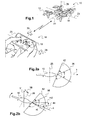
- the Figure 2a illustrates schematically, in profile, the attitude of the drone when it is motionless, in a state of sustenance.
- the field covered by a front camera 14 of conventional type has been schematized at 36, for example a camera covering a field of 54 ° and whose axis of vision ⁇ is centered on the horizon.
- the axis 26 of the drone will be tilted forward by an angle ⁇ (pitch angle) with respect to the vertical V.
- This inclination towards the before, schematized by the arrow 38, implies an inclination of the same value, shown schematically by the arrow 40, of the axis ⁇ of the camera relative to the plane of the horizon HZ.
- the ⁇ axis oscillates permanently around the direction of the horizon HZ, which will be reflected in the image by permanent oscillation movements up and down.
- the image captured by the camera equipped with this fisheye lens will certainly undergo the same movements of oscillation and rotation as a conventional camera but we will use only part of the field captured by this camera by selecting a particular window corresponding to the angular sector 36 captured by a conventional camera, and which will be dynamically moved in the hemispherical image in the opposite direction of the movements of the drone as determined by the inertial unit, in order to annihilate the oscillations that otherwise would be observed on the image.
- the Figure 3 shows in (a1) an example of a scene, as collected by the sensor of the video camera equipped with the fisheye lens .
- the image I of this scene has very strong geometric distortions, inherent to the hemispherical or quasi-hemispherical coverage of the fisheye lens , rectified on the flat surface of the sensor.
- a “capture zone” ZC is thus defined containing raw pixel data including the raw “useful zone” ZU B which will correspond to the field of the "virtual camera” after compensation for geometric distortions introduced by the fisheye lens .
- the views (a2) and (a3) of the Figure 3 illustrate the processing performed on the pixel data of the capture zone ZC to arrive at the final image compensated for the geometric distortions: from the pixel data transferred from the capture zone ZC (view (a2)) an algorithm extracts the pixel data of the gross useful area ZU B and applies to them a mesh of triangles (technique in itself known) then straightens the image by stretching each triangle, to give a corrected useful image ZU R (view (a3)) with rectified pixel data.
- the strongly curved horizontal lines of the fisheye image will thus be corrected for make rectilinear and produce an image corresponding to a natural vision, devoid of geometric distortions.
- the views (b1) - (b3) of the Figure 3 are homologous to the views (a1) - (a3), in a configuration where the attitude of the drone changes due to an inclination thereof forward (rotation about its pitch axis), consecutive inclination by example to a transition from a stationary configuration, hovering, to a forward progression configuration (the linear speed of the drone being even greater than its inclination is strong).
- the capture zone ZC is displaced towards the top of the image, thus in a direction opposite to that of the inclination of the drone. If the relative position of the gross useful area ZU B remains substantially the same within the catch area ZC (to allow the continuation of the target scene), the catch area will now include a much larger part of soil S than of sky C: if we compare the views (a2) and (b2), we see that in the initial configuration (view (a2)) the sky / soil ratio is about 50/50% , while in the modified configuration ((view (b2)) the sky / soil ratio is about 25/75%, and if it is strongly shifted up the capture area may include X areas that are located outside the region of the circular image formed by the fisheye lens on the sensor.
- the Figure 4 illustrates the histograms obtained by analyzing the brightness of the pixels of the image from the capture zone ZC, respectively in (a) in the case of the view (a2) and in (b) in the case of the view (b2 ).
- the dropping of the drone towards the front results in a significant modification of the brightness histogram, with a shift to the left of the average value M due to the increase in the ground ratio. / sky in the image of the ZC area.
- the self-exposure algorithm will interpret this change in the mean value M as a darkening of the image, which will automatically compensated by an increase in the exposure time and / or sensitivity of the camera.
- the final images (a3) and (b3) obtained respectively images of the uprighted useful area ZU R ), if they present the user with the same frame of the scene, will differ in their exposure setting. image of the view (b3) being clearer than that of the view (a3).
- the object of the present invention is to correct this defect.
- the Figure 5 illustrates in block diagram form the various modules involved in the implementation of the invention.
- the front camera 14 of the drone delivers a raw image signal corresponding to the image I.
- This camera mechanically linked to the body of the drone, is subject to angular displacements which are measured by an inertial unit (IMU) 12 linked to the body of drone and so to the camera.
- IMU inertial unit
- the rotations of the camera are given by the pitch angle ⁇ , the roll angle ⁇ and the yaw angle ⁇ describing the inclination of the drone in three dimensions with respect to a fixed landmark (Euler angles ).
- These data are applied to an angle prediction module 48 driving a module for calculating the position of the capture zone ZC in the image I.
- a video processing module 52 receives as input the raw image signal I and ensures various windowing operations as a function of the position of the capture zone ZC calculated by the module 50, image stabilization, extraction and recovery of the useful area, to output to the user a signal d useful image ZU R for transmission to the user, display and recording possible.
- the module 52 also provides control (diagrammatically by the return 54) of the operating parameters of the camera, namely the AE self-exposure control, the AWB white balance and the AF autofocus.
- the module 52 also corrects, according to the invention, the defect described above relating to the automatic calculation of these operating parameters of the camera, as will be described below.
- the Figure 6 is a flowchart explaining the main successive steps of implementation of the invention, in a first and a second embodiment thereof.
- This flow chart 100 comprises an initial step (block 102) of collection of the raw image I by the camera, followed by a step (block 104) of extraction in this raw image of the capture zone ZC as a function of the data of the image. attitude of the drone delivered by the IMU inertial unit.
- step (block 106), characteristic of the invention consists of an analysis of the image data of the capture zone, in the manner that will be explained in detail below with reference to FIGS. Figures 7 and 8 , for the delivery of control parameters of the camera, including the self-exposure parameter.
- the content of the capture zone ZC is then subjected to a treatment (block 108) of extraction of the gross useful area ZU B and reprojection of this gross useful area ZU B to give the rectified pay zone ZU R , corresponding to the final rectified image delivered to the user.
- this analysis is performed on the basis of the image from the image originally contained in the capture zone ZC (downstream of the block 104), before the reprojection step (block 108), so on a distorted version of the image.
- the Figure 7 illustrates the zones of analysis of the capture zone according to the first embodiment of the invention, analysis operated from ROI regions of interest automatically defined inside the image from the capture zone.
- the image analysis device defines (according to techniques known per se, which will not be described in more detail) a plurality of regions of interest ROI, which are geometric selections of areas of reduced size in the image to be analyzed, a brightness histogram being established for each of these areas.
- the selfexposure algorithm analyzes and compares the histograms corresponding to the different ROIs and adjusts the exposure level accordingly, according to analysis techniques also known per se.
- the ROIs are distributed in the image coming from the capture zone so as to be located totally or partially within the gross useful area ZU B , that is, if the ROI definition algorithm generates ROIs outside the gross useful area ZU B , the latter will be excluded from the subsequent analysis for control of self-exposure.
- the pixel data located outside the region of the image formed on the sensor by the objective are excluded from the analysis. In other words, the pixels outside the image circle are ignored for the calculation of self-exposure.
- each of the regions of interest ROI 1 ... ROI n is assigned a weighting value taking into account the greater or lesser extent of the overlap of the concerned ROI with the gross user service area ZU B defined in FIG. within the capture zone: the weighting will be maximum for the ROI fully included in the ZU B zone, zero for the ROI located entirely outside the ZU B zone (which excludes them from the analysis ), and intermediate for the ROI partially included in the ZU B zone (the higher the weight of the area of the ROI within the ZU B area).
- the Figure 8 illustrates a second embodiment, in which the ROIs are no longer defined dynamically and with a variable size, but in the form of a regular grid of the image taken from the capture zone ZC, with a GR grid each of which square or elementary rectangle ROI (i, j) will be assigned a variable weighting according to its more or less overlapping character with the zone ZU B , in the same way as in the first embodiment, exposed in connection with the Figure 7.
- the Figure 9 is a flowchart explaining the main successive steps of implementation of the invention, in a third embodiment thereof.
- the analysis of the image data is not performed on the image obtained from the initial version, deformed, of the image (capture zone ZC and gross useful area ZU B ) with a weighting applied to each region of interest, but on the image from the rectified image after the reprojection step.
- the blocks 202 image collection
- 204 extraction of the capture zone ZC
- 206 extraction and reprojection of the user zone
- the data analysis step for controlling the self-exposure parameters of the camera (block 208) is performed downstream of block 206, that is to say on the corrected version of the image.
- Selfexposure then works in a conventional manner (automatic definition of ROI, etc.) without it being necessary to apply to each ROI a weighting value reflecting the position of this ROI with respect to the gross useful area ZU B.
Landscapes
- Engineering & Computer Science (AREA)
- Multimedia (AREA)
- Signal Processing (AREA)
- Aviation & Aerospace Engineering (AREA)
- Physics & Mathematics (AREA)
- General Physics & Mathematics (AREA)
- Radar, Positioning & Navigation (AREA)
- Remote Sensing (AREA)
- Automation & Control Theory (AREA)
- Theoretical Computer Science (AREA)
- Computer Vision & Pattern Recognition (AREA)
- Studio Devices (AREA)
- Geometry (AREA)
- Details Of Cameras Including Film Mechanisms (AREA)
- Stereoscopic And Panoramic Photography (AREA)
Applications Claiming Priority (1)
| Application Number | Priority Date | Filing Date | Title |
|---|---|---|---|
| FR1558420A FR3041134B1 (fr) | 2015-09-10 | 2015-09-10 | Drone avec camera a visee frontale dont les parametres de controle, notamment l'autoexposition, sont rendus independant de l'attitude. |
Publications (2)
| Publication Number | Publication Date |
|---|---|
| EP3142353A1 true EP3142353A1 (de) | 2017-03-15 |
| EP3142353B1 EP3142353B1 (de) | 2019-12-18 |
Family
ID=54545300
Family Applications (1)
| Application Number | Title | Priority Date | Filing Date |
|---|---|---|---|
| EP16188012.5A Active EP3142353B1 (de) | 2015-09-10 | 2016-09-09 | Drohne mit frontal ausgerichteter kamera, deren kontrollparameter, insbesondere die automatische belichtung, unabhängig von der haltung konzipiert sind |
Country Status (5)
| Country | Link |
|---|---|
| US (1) | US20170236291A1 (de) |
| EP (1) | EP3142353B1 (de) |
| JP (1) | JP2017103751A (de) |
| CN (1) | CN106534627A (de) |
| FR (1) | FR3041134B1 (de) |
Families Citing this family (22)
| Publication number | Priority date | Publication date | Assignee | Title |
|---|---|---|---|---|
| FR3038482B1 (fr) * | 2015-06-30 | 2017-08-11 | Parrot | Bloc camera apte a etre embarque dans un drone pour cartographier un terrain et procede de gestion de capture d'images par un bloc camera |
| JP6942940B2 (ja) * | 2016-03-14 | 2021-09-29 | カシオ計算機株式会社 | 画像処理装置、画像処理方法及びプログラム |
| WO2018034033A1 (ja) * | 2016-08-16 | 2018-02-22 | 本郷飛行機株式会社 | 通信制御装置 |
| US10538326B1 (en) * | 2016-08-31 | 2020-01-21 | Amazon Technologies, Inc. | Flare detection and avoidance in stereo vision systems |
| US20180210442A1 (en) * | 2017-01-23 | 2018-07-26 | Qualcomm Incorporated | Systems and methods for controlling a vehicle using a mobile device |
| JP6606530B2 (ja) * | 2017-06-20 | 2019-11-13 | キヤノン株式会社 | 画像処理装置およびその制御方法、撮像装置、監視システム |
| JP7057637B2 (ja) * | 2017-08-23 | 2022-04-20 | キヤノン株式会社 | 制御装置、制御システム、制御方法、プログラム、及び記憶媒体 |
| JP6656214B2 (ja) * | 2017-09-04 | 2020-03-04 | キヤノン株式会社 | 飛行体、移動装置、制御方法、プログラム、及び記憶媒体 |
| JP7086552B2 (ja) * | 2017-09-22 | 2022-06-20 | キヤノン株式会社 | 情報処理装置、撮像装置、情報処理方法及びプログラム |
| WO2019061398A1 (zh) * | 2017-09-30 | 2019-04-04 | 深圳市大疆创新科技有限公司 | 补光控制方法、补光控制模块及无人飞行器 |
| US20200379487A1 (en) * | 2017-10-25 | 2020-12-03 | Rakuten, Inc. | Unmanned aerial vehicle control system, unmanned aerial vehicle control method, and program |
| JP6501091B1 (ja) * | 2017-10-30 | 2019-04-17 | エスゼット ディージェイアイ テクノロジー カンパニー リミテッドSz Dji Technology Co.,Ltd | 制御装置、撮像装置、移動体、制御方法、及びプログラム |
| JP6459012B1 (ja) * | 2017-10-30 | 2019-01-30 | エスゼット ディージェイアイ テクノロジー カンパニー リミテッドSz Dji Technology Co.,Ltd | 制御装置、撮像装置、飛行体、制御方法、及びプログラム |
| CN107977993A (zh) * | 2017-11-17 | 2018-05-01 | 杨俊刚 | 一种针对光场阵列相机的基于重投影的重聚焦方法及系统 |
| JP6688277B2 (ja) * | 2017-12-27 | 2020-04-28 | 本田技研工業株式会社 | プログラム、学習処理方法、学習モデル、データ構造、学習装置、および物体認識装置 |
| RU183717U1 (ru) * | 2018-06-26 | 2018-10-01 | Российская Федерация, от имени которой выступает ФОНД ПЕРСПЕКТИВНЫХ ИССЛЕДОВАНИЙ | Беспилотный летательный аппарат мультироторного типа |
| CN109698913B (zh) * | 2018-12-29 | 2020-12-04 | 深圳市道通智能航空技术有限公司 | 一种图像显示方法、装置和电子设备 |
| CN111316636B (zh) * | 2019-03-27 | 2021-11-16 | 深圳市大疆创新科技有限公司 | 旋转式拍摄方法、控制装置、可移动平台及存储介质 |
| WO2020215274A1 (zh) * | 2019-04-25 | 2020-10-29 | 深圳市大疆创新科技有限公司 | 无人机及其拍摄控制方法 |
| CN114727028B (zh) * | 2019-12-30 | 2024-04-16 | 深圳市道通智能航空技术股份有限公司 | 图像曝光方法及装置、无人机 |
| KR20210101999A (ko) * | 2020-02-11 | 2021-08-19 | 삼성전자주식회사 | 화질 조정을 지원하는 전자 장치 및 그 방법 |
| US20230292020A1 (en) * | 2020-10-27 | 2023-09-14 | Qualcomm Incorporated | Lens distortion correction for image processing |
Citations (13)
| Publication number | Priority date | Publication date | Assignee | Title |
|---|---|---|---|---|
| JP2003267295A (ja) * | 2002-03-14 | 2003-09-25 | Foundation For Nara Institute Of Science & Technology | 遠隔操縦システム |
| US20080118180A1 (en) * | 2006-11-22 | 2008-05-22 | Sony Corporation | Image processing apparatus and image processing method |
| WO2010061099A2 (fr) | 2008-11-27 | 2010-06-03 | Parrot | Dispositif de pilotage d'un drone |
| US20110001831A1 (en) * | 2009-07-03 | 2011-01-06 | Sanyo Electric Co., Ltd. | Video Camera |
| EP2364757A1 (de) | 2010-03-11 | 2011-09-14 | Parrot | Verfahren und Gerät zur Fernbedienung einer Drohne, insbesondere einer Drohne mit Drehflügeln |
| US20120307042A1 (en) * | 2011-06-02 | 2012-12-06 | Hon Hai Precision Industry Co., Ltd. | System and method for controlling unmanned aerial vehicle |
| US20130021520A1 (en) | 2011-07-20 | 2013-01-24 | Samsung Electronics Co. Ltd. | Apparatus and method for automatically adjusting focus in image capturing device |
| EP2613214A1 (de) | 2012-01-05 | 2013-07-10 | Parrot | Steuerungsverfahren einer Drehflügel-Drone, um Aufnahmen mit einer Bordkamera mit Minimierung der störenden Bewegungen zu machen |
| EP2613213A1 (de) | 2012-01-04 | 2013-07-10 | Parrot | Intuitives Steuerungsverfahren einer Drone mit Hilfe eines Fernbedienungsgeräts |
| US20140176722A1 (en) * | 2012-12-25 | 2014-06-26 | Casio Computer Co., Ltd. | Imaging device, imaging control method and storage medium |
| FR3000813A1 (fr) * | 2013-01-04 | 2014-07-11 | Parrot | Drone a voilure tournante comprenant des moyens de determination autonome de position dans un repere absolu lie au sol. |
| US20150222816A1 (en) | 2012-09-11 | 2015-08-06 | Makoto Shohara | Imaging controller and imaging control method and program |
| EP2933775A1 (de) | 2014-04-16 | 2015-10-21 | Parrot | Drehflügel-drohne, die mit einer videokamera ausgerüstet ist, die stabilisierte bildsequenzen liefert |
-
2015
- 2015-09-10 FR FR1558420A patent/FR3041134B1/fr not_active Expired - Fee Related
-
2016
- 2016-09-02 US US15/256,423 patent/US20170236291A1/en not_active Abandoned
- 2016-09-08 JP JP2016175147A patent/JP2017103751A/ja not_active Withdrawn
- 2016-09-09 CN CN201610816480.8A patent/CN106534627A/zh not_active Withdrawn
- 2016-09-09 EP EP16188012.5A patent/EP3142353B1/de active Active
Patent Citations (13)
| Publication number | Priority date | Publication date | Assignee | Title |
|---|---|---|---|---|
| JP2003267295A (ja) * | 2002-03-14 | 2003-09-25 | Foundation For Nara Institute Of Science & Technology | 遠隔操縦システム |
| US20080118180A1 (en) * | 2006-11-22 | 2008-05-22 | Sony Corporation | Image processing apparatus and image processing method |
| WO2010061099A2 (fr) | 2008-11-27 | 2010-06-03 | Parrot | Dispositif de pilotage d'un drone |
| US20110001831A1 (en) * | 2009-07-03 | 2011-01-06 | Sanyo Electric Co., Ltd. | Video Camera |
| EP2364757A1 (de) | 2010-03-11 | 2011-09-14 | Parrot | Verfahren und Gerät zur Fernbedienung einer Drohne, insbesondere einer Drohne mit Drehflügeln |
| US20120307042A1 (en) * | 2011-06-02 | 2012-12-06 | Hon Hai Precision Industry Co., Ltd. | System and method for controlling unmanned aerial vehicle |
| US20130021520A1 (en) | 2011-07-20 | 2013-01-24 | Samsung Electronics Co. Ltd. | Apparatus and method for automatically adjusting focus in image capturing device |
| EP2613213A1 (de) | 2012-01-04 | 2013-07-10 | Parrot | Intuitives Steuerungsverfahren einer Drone mit Hilfe eines Fernbedienungsgeräts |
| EP2613214A1 (de) | 2012-01-05 | 2013-07-10 | Parrot | Steuerungsverfahren einer Drehflügel-Drone, um Aufnahmen mit einer Bordkamera mit Minimierung der störenden Bewegungen zu machen |
| US20150222816A1 (en) | 2012-09-11 | 2015-08-06 | Makoto Shohara | Imaging controller and imaging control method and program |
| US20140176722A1 (en) * | 2012-12-25 | 2014-06-26 | Casio Computer Co., Ltd. | Imaging device, imaging control method and storage medium |
| FR3000813A1 (fr) * | 2013-01-04 | 2014-07-11 | Parrot | Drone a voilure tournante comprenant des moyens de determination autonome de position dans un repere absolu lie au sol. |
| EP2933775A1 (de) | 2014-04-16 | 2015-10-21 | Parrot | Drehflügel-drohne, die mit einer videokamera ausgerüstet ist, die stabilisierte bildsequenzen liefert |
Non-Patent Citations (4)
| Title |
|---|
| ANONYMOUS: "The New Parrot Bebop Drone: Built for Stabilized Aerial Video | explora", 6 October 2014 (2014-10-06), XP055233862, Retrieved from the Internet <URL:https://web.archive.org/web/20141006214813/http://www.bhphotovideo.com/explora/video/news/new-parrot-bebop-drone-built-stabilized-aerial-video> [retrieved on 20151204] * |
| R. MIYAUCHI ET AL.: "Development of Omni-Directional Image Stabilization System Using Camera Posture Information", PROCEEDINGS OF THE 2007 IEEE INTERNATIONAL CONFÉRENCE ON ROBOTICS AND BIOMIMETICS, 15 December 2007 (2007-12-15), pages 920 - 925 |
| RYO MIYAUCHI ET AL: "Development of omni-directional image stabilization system using camera posture information", ROBOTICS AND BIOMIMETICS, 2007. ROBIO 2007. IEEE INTERNATIONAL CONFERENCE ON, IEEE, PISCATAWAY, NJ, USA, 15 December 2007 (2007-12-15), pages 920 - 925, XP031252928, ISBN: 978-1-4244-1761-2 * |
| TIMOTHY MCDOUGAL, THE NEW PARROT BEBOP DRONE: BUILT FOR STABILIZED AERIAL VIDEO, 6 October 2014 (2014-10-06) |
Also Published As
| Publication number | Publication date |
|---|---|
| FR3041134B1 (fr) | 2017-09-29 |
| EP3142353B1 (de) | 2019-12-18 |
| FR3041134A1 (fr) | 2017-03-17 |
| CN106534627A (zh) | 2017-03-22 |
| US20170236291A1 (en) | 2017-08-17 |
| JP2017103751A (ja) | 2017-06-08 |
Similar Documents
| Publication | Publication Date | Title |
|---|---|---|
| EP3142353B1 (de) | Drohne mit frontal ausgerichteter kamera, deren kontrollparameter, insbesondere die automatische belichtung, unabhängig von der haltung konzipiert sind | |
| EP3142354B1 (de) | Drohne mit frontal ausgerichteter kamera mit bildsegmentierung des himmels für die kontrolle der automatischen belichtung | |
| EP3048789B1 (de) | Drohne, die mit einer videokamera und mitteln zur kompensation von bildartefakten ausgestattet ist, die in den wichtigsten wankwinkelbereichen produziert werden | |
| EP2933775B1 (de) | Drehflügel-drohne, die mit einer videokamera ausgerüstet ist, die stabilisierte bildsequenzen liefert | |
| EP3078402B1 (de) | System zum steuern einer drohne im tauchgang | |
| EP3025770B1 (de) | Videosystem zum steuern einer drohne im immersionmodus | |
| EP3086195B1 (de) | System zum steuern einer drohne im immersionmodus | |
| EP3171589B1 (de) | Drohne, die mit einer videokamera ausgestattet ist, die wobble-effekt-korrigierte bildsequenzen liefert | |
| EP3273318B1 (de) | Autonomes aufnahmesystem von animierten bildern durch eine drohne mit zielverfolgung und verbesserter lokalisierung des ziels | |
| EP3076258B1 (de) | Drohne mit einer videokamera mit vertikalem visier mit kompensation der unvermittelten drehbewegungen für die einschätzung horizontaler geschwindigkeiten | |
| EP3316068A1 (de) | Autonomes aufnahmesystem von animierten bildern durch eine drohne mit zielverfolgung und aufrechterhaltung des aufnahmewinkels des ziels | |
| EP3306428A1 (de) | Autonomes aufnahmesystem von animierten bildern durch eine drohne mit zielverfolgung und aufrechterhaltung des aufnahmewinkels des ziels | |
| JP2017085551A (ja) | ドローンに搭載されたカメラの露出時間を決定する方法、および関連するドローン | |
| EP3273317A1 (de) | Autonomes aufnahmesystem von animierten bildern, das eine drohne und eine bodenstation umfasst, und entsprechendes verfahren | |
| EP3276591A1 (de) | Drohne mit einem hindernisausweichsystem | |
| EP3392728A1 (de) | Steuerungsverfahren einer drehflügel-drohne, entsprechende software, entsprechendes elektronisches gerät und entsprechende drohne | |
| EP3281870A1 (de) | Videoerfassungsverfahren für eine drohne, entsprechendes computerprogramm und entsprechendes elektronisches system zur erfassung eines videos | |
| FR3079943A1 (fr) | Dispositif electronique et procede de commande d'un drone avec effet de travelling compense, programme d'ordinateur associe | |
| FR3020168A1 (fr) | Drone a voilure tournante muni d'une camera video delivrant des sequences d'images stabilisees | |
| FR3082012A1 (fr) | Dispositif electronique, et procede, de commande d'un drone, programme d'ordinateur associe |
Legal Events
| Date | Code | Title | Description |
|---|---|---|---|
| PUAI | Public reference made under article 153(3) epc to a published international application that has entered the european phase |
Free format text: ORIGINAL CODE: 0009012 |
|
| STAA | Information on the status of an ep patent application or granted ep patent |
Free format text: STATUS: THE APPLICATION HAS BEEN PUBLISHED |
|
| AK | Designated contracting states |
Kind code of ref document: A1 Designated state(s): AL AT BE BG CH CY CZ DE DK EE ES FI FR GB GR HR HU IE IS IT LI LT LU LV MC MK MT NL NO PL PT RO RS SE SI SK SM TR |
|
| AX | Request for extension of the european patent |
Extension state: BA ME |
|
| STAA | Information on the status of an ep patent application or granted ep patent |
Free format text: STATUS: REQUEST FOR EXAMINATION WAS MADE |
|
| 17P | Request for examination filed |
Effective date: 20170828 |
|
| RBV | Designated contracting states (corrected) |
Designated state(s): AL AT BE BG CH CY CZ DE DK EE ES FI FR GB GR HR HU IE IS IT LI LT LU LV MC MK MT NL NO PL PT RO RS SE SI SK SM TR |
|
| STAA | Information on the status of an ep patent application or granted ep patent |
Free format text: STATUS: EXAMINATION IS IN PROGRESS |
|
| 17Q | First examination report despatched |
Effective date: 20190225 |
|
| GRAP | Despatch of communication of intention to grant a patent |
Free format text: ORIGINAL CODE: EPIDOSNIGR1 |
|
| STAA | Information on the status of an ep patent application or granted ep patent |
Free format text: STATUS: GRANT OF PATENT IS INTENDED |
|
| INTG | Intention to grant announced |
Effective date: 20190712 |
|
| GRAS | Grant fee paid |
Free format text: ORIGINAL CODE: EPIDOSNIGR3 |
|
| GRAA | (expected) grant |
Free format text: ORIGINAL CODE: 0009210 |
|
| STAA | Information on the status of an ep patent application or granted ep patent |
Free format text: STATUS: THE PATENT HAS BEEN GRANTED |
|
| AK | Designated contracting states |
Kind code of ref document: B1 Designated state(s): AL AT BE BG CH CY CZ DE DK EE ES FI FR GB GR HR HU IE IS IT LI LT LU LV MC MK MT NL NO PL PT RO RS SE SI SK SM TR |
|
| REG | Reference to a national code |
Ref country code: CH Ref legal event code: EP |
|
| REG | Reference to a national code |
Ref country code: DE Ref legal event code: R096 Ref document number: 602016026291 Country of ref document: DE |
|
| REG | Reference to a national code |
Ref country code: IE Ref legal event code: FG4D Free format text: LANGUAGE OF EP DOCUMENT: FRENCH |
|
| REG | Reference to a national code |
Ref country code: AT Ref legal event code: REF Ref document number: 1215875 Country of ref document: AT Kind code of ref document: T Effective date: 20200115 |
|
| REG | Reference to a national code |
Ref country code: NL Ref legal event code: MP Effective date: 20191218 |
|
| PG25 | Lapsed in a contracting state [announced via postgrant information from national office to epo] |
Ref country code: SE Free format text: LAPSE BECAUSE OF FAILURE TO SUBMIT A TRANSLATION OF THE DESCRIPTION OR TO PAY THE FEE WITHIN THE PRESCRIBED TIME-LIMIT Effective date: 20191218 Ref country code: LV Free format text: LAPSE BECAUSE OF FAILURE TO SUBMIT A TRANSLATION OF THE DESCRIPTION OR TO PAY THE FEE WITHIN THE PRESCRIBED TIME-LIMIT Effective date: 20191218 Ref country code: BG Free format text: LAPSE BECAUSE OF FAILURE TO SUBMIT A TRANSLATION OF THE DESCRIPTION OR TO PAY THE FEE WITHIN THE PRESCRIBED TIME-LIMIT Effective date: 20200318 Ref country code: FI Free format text: LAPSE BECAUSE OF FAILURE TO SUBMIT A TRANSLATION OF THE DESCRIPTION OR TO PAY THE FEE WITHIN THE PRESCRIBED TIME-LIMIT Effective date: 20191218 Ref country code: GR Free format text: LAPSE BECAUSE OF FAILURE TO SUBMIT A TRANSLATION OF THE DESCRIPTION OR TO PAY THE FEE WITHIN THE PRESCRIBED TIME-LIMIT Effective date: 20200319 Ref country code: LT Free format text: LAPSE BECAUSE OF FAILURE TO SUBMIT A TRANSLATION OF THE DESCRIPTION OR TO PAY THE FEE WITHIN THE PRESCRIBED TIME-LIMIT Effective date: 20191218 Ref country code: NO Free format text: LAPSE BECAUSE OF FAILURE TO SUBMIT A TRANSLATION OF THE DESCRIPTION OR TO PAY THE FEE WITHIN THE PRESCRIBED TIME-LIMIT Effective date: 20200318 |
|
| REG | Reference to a national code |
Ref country code: LT Ref legal event code: MG4D |
|
| PG25 | Lapsed in a contracting state [announced via postgrant information from national office to epo] |
Ref country code: RS Free format text: LAPSE BECAUSE OF FAILURE TO SUBMIT A TRANSLATION OF THE DESCRIPTION OR TO PAY THE FEE WITHIN THE PRESCRIBED TIME-LIMIT Effective date: 20191218 Ref country code: HR Free format text: LAPSE BECAUSE OF FAILURE TO SUBMIT A TRANSLATION OF THE DESCRIPTION OR TO PAY THE FEE WITHIN THE PRESCRIBED TIME-LIMIT Effective date: 20191218 |
|
| PG25 | Lapsed in a contracting state [announced via postgrant information from national office to epo] |
Ref country code: AL Free format text: LAPSE BECAUSE OF FAILURE TO SUBMIT A TRANSLATION OF THE DESCRIPTION OR TO PAY THE FEE WITHIN THE PRESCRIBED TIME-LIMIT Effective date: 20191218 |
|
| PG25 | Lapsed in a contracting state [announced via postgrant information from national office to epo] |
Ref country code: RO Free format text: LAPSE BECAUSE OF FAILURE TO SUBMIT A TRANSLATION OF THE DESCRIPTION OR TO PAY THE FEE WITHIN THE PRESCRIBED TIME-LIMIT Effective date: 20191218 Ref country code: CZ Free format text: LAPSE BECAUSE OF FAILURE TO SUBMIT A TRANSLATION OF THE DESCRIPTION OR TO PAY THE FEE WITHIN THE PRESCRIBED TIME-LIMIT Effective date: 20191218 Ref country code: PT Free format text: LAPSE BECAUSE OF FAILURE TO SUBMIT A TRANSLATION OF THE DESCRIPTION OR TO PAY THE FEE WITHIN THE PRESCRIBED TIME-LIMIT Effective date: 20200513 Ref country code: NL Free format text: LAPSE BECAUSE OF FAILURE TO SUBMIT A TRANSLATION OF THE DESCRIPTION OR TO PAY THE FEE WITHIN THE PRESCRIBED TIME-LIMIT Effective date: 20191218 Ref country code: EE Free format text: LAPSE BECAUSE OF FAILURE TO SUBMIT A TRANSLATION OF THE DESCRIPTION OR TO PAY THE FEE WITHIN THE PRESCRIBED TIME-LIMIT Effective date: 20191218 |
|
| PG25 | Lapsed in a contracting state [announced via postgrant information from national office to epo] |
Ref country code: SK Free format text: LAPSE BECAUSE OF FAILURE TO SUBMIT A TRANSLATION OF THE DESCRIPTION OR TO PAY THE FEE WITHIN THE PRESCRIBED TIME-LIMIT Effective date: 20191218 Ref country code: IS Free format text: LAPSE BECAUSE OF FAILURE TO SUBMIT A TRANSLATION OF THE DESCRIPTION OR TO PAY THE FEE WITHIN THE PRESCRIBED TIME-LIMIT Effective date: 20200418 Ref country code: SM Free format text: LAPSE BECAUSE OF FAILURE TO SUBMIT A TRANSLATION OF THE DESCRIPTION OR TO PAY THE FEE WITHIN THE PRESCRIBED TIME-LIMIT Effective date: 20191218 |
|
| REG | Reference to a national code |
Ref country code: DE Ref legal event code: R097 Ref document number: 602016026291 Country of ref document: DE |
|
| REG | Reference to a national code |
Ref country code: AT Ref legal event code: MK05 Ref document number: 1215875 Country of ref document: AT Kind code of ref document: T Effective date: 20191218 |
|
| PLBE | No opposition filed within time limit |
Free format text: ORIGINAL CODE: 0009261 |
|
| STAA | Information on the status of an ep patent application or granted ep patent |
Free format text: STATUS: NO OPPOSITION FILED WITHIN TIME LIMIT |
|
| PG25 | Lapsed in a contracting state [announced via postgrant information from national office to epo] |
Ref country code: ES Free format text: LAPSE BECAUSE OF FAILURE TO SUBMIT A TRANSLATION OF THE DESCRIPTION OR TO PAY THE FEE WITHIN THE PRESCRIBED TIME-LIMIT Effective date: 20191218 Ref country code: DK Free format text: LAPSE BECAUSE OF FAILURE TO SUBMIT A TRANSLATION OF THE DESCRIPTION OR TO PAY THE FEE WITHIN THE PRESCRIBED TIME-LIMIT Effective date: 20191218 |
|
| 26N | No opposition filed |
Effective date: 20200921 |
|
| PG25 | Lapsed in a contracting state [announced via postgrant information from national office to epo] |
Ref country code: AT Free format text: LAPSE BECAUSE OF FAILURE TO SUBMIT A TRANSLATION OF THE DESCRIPTION OR TO PAY THE FEE WITHIN THE PRESCRIBED TIME-LIMIT Effective date: 20191218 Ref country code: SI Free format text: LAPSE BECAUSE OF FAILURE TO SUBMIT A TRANSLATION OF THE DESCRIPTION OR TO PAY THE FEE WITHIN THE PRESCRIBED TIME-LIMIT Effective date: 20191218 |
|
| PG25 | Lapsed in a contracting state [announced via postgrant information from national office to epo] |
Ref country code: IT Free format text: LAPSE BECAUSE OF FAILURE TO SUBMIT A TRANSLATION OF THE DESCRIPTION OR TO PAY THE FEE WITHIN THE PRESCRIBED TIME-LIMIT Effective date: 20191218 |
|
| PG25 | Lapsed in a contracting state [announced via postgrant information from national office to epo] |
Ref country code: PL Free format text: LAPSE BECAUSE OF FAILURE TO SUBMIT A TRANSLATION OF THE DESCRIPTION OR TO PAY THE FEE WITHIN THE PRESCRIBED TIME-LIMIT Effective date: 20191218 |
|
| REG | Reference to a national code |
Ref country code: DE Ref legal event code: R119 Ref document number: 602016026291 Country of ref document: DE |
|
| PG25 | Lapsed in a contracting state [announced via postgrant information from national office to epo] |
Ref country code: MC Free format text: LAPSE BECAUSE OF FAILURE TO SUBMIT A TRANSLATION OF THE DESCRIPTION OR TO PAY THE FEE WITHIN THE PRESCRIBED TIME-LIMIT Effective date: 20191218 |
|
| REG | Reference to a national code |
Ref country code: CH Ref legal event code: PL |
|
| GBPC | Gb: european patent ceased through non-payment of renewal fee |
Effective date: 20200909 |
|
| REG | Reference to a national code |
Ref country code: BE Ref legal event code: MM Effective date: 20200930 |
|
| PG25 | Lapsed in a contracting state [announced via postgrant information from national office to epo] |
Ref country code: LU Free format text: LAPSE BECAUSE OF NON-PAYMENT OF DUE FEES Effective date: 20200909 |
|
| PG25 | Lapsed in a contracting state [announced via postgrant information from national office to epo] |
Ref country code: DE Free format text: LAPSE BECAUSE OF NON-PAYMENT OF DUE FEES Effective date: 20210401 |
|
| PG25 | Lapsed in a contracting state [announced via postgrant information from national office to epo] |
Ref country code: LI Free format text: LAPSE BECAUSE OF NON-PAYMENT OF DUE FEES Effective date: 20200930 Ref country code: IE Free format text: LAPSE BECAUSE OF NON-PAYMENT OF DUE FEES Effective date: 20200909 Ref country code: GB Free format text: LAPSE BECAUSE OF NON-PAYMENT OF DUE FEES Effective date: 20200909 Ref country code: BE Free format text: LAPSE BECAUSE OF NON-PAYMENT OF DUE FEES Effective date: 20200930 Ref country code: CH Free format text: LAPSE BECAUSE OF NON-PAYMENT OF DUE FEES Effective date: 20200930 |
|
| PG25 | Lapsed in a contracting state [announced via postgrant information from national office to epo] |
Ref country code: TR Free format text: LAPSE BECAUSE OF FAILURE TO SUBMIT A TRANSLATION OF THE DESCRIPTION OR TO PAY THE FEE WITHIN THE PRESCRIBED TIME-LIMIT Effective date: 20191218 Ref country code: MT Free format text: LAPSE BECAUSE OF FAILURE TO SUBMIT A TRANSLATION OF THE DESCRIPTION OR TO PAY THE FEE WITHIN THE PRESCRIBED TIME-LIMIT Effective date: 20191218 Ref country code: CY Free format text: LAPSE BECAUSE OF FAILURE TO SUBMIT A TRANSLATION OF THE DESCRIPTION OR TO PAY THE FEE WITHIN THE PRESCRIBED TIME-LIMIT Effective date: 20191218 |
|
| PG25 | Lapsed in a contracting state [announced via postgrant information from national office to epo] |
Ref country code: MK Free format text: LAPSE BECAUSE OF FAILURE TO SUBMIT A TRANSLATION OF THE DESCRIPTION OR TO PAY THE FEE WITHIN THE PRESCRIBED TIME-LIMIT Effective date: 20191218 |
|
| PGFP | Annual fee paid to national office [announced via postgrant information from national office to epo] |
Ref country code: FR Payment date: 20230905 Year of fee payment: 8 |