EP3141643B1 - Article en tissu eponge comprenant des fils continus synthetiques et son procede de fabrication - Google Patents
Article en tissu eponge comprenant des fils continus synthetiques et son procede de fabrication Download PDFInfo
- Publication number
- EP3141643B1 EP3141643B1 EP16188260.0A EP16188260A EP3141643B1 EP 3141643 B1 EP3141643 B1 EP 3141643B1 EP 16188260 A EP16188260 A EP 16188260A EP 3141643 B1 EP3141643 B1 EP 3141643B1
- Authority
- EP
- European Patent Office
- Prior art keywords
- pile
- yarns
- component
- loops
- ground
- Prior art date
- Legal status (The legal status is an assumption and is not a legal conclusion. Google has not performed a legal analysis and makes no representation as to the accuracy of the status listed.)
- Active
Links
- 238000004519 manufacturing process Methods 0.000 title claims description 7
- 239000004744 fabric Substances 0.000 claims description 62
- 239000000835 fiber Substances 0.000 claims description 48
- 229920001169 thermoplastic Polymers 0.000 claims description 34
- 239000004416 thermosoftening plastic Substances 0.000 claims description 33
- 238000009941 weaving Methods 0.000 claims description 26
- 238000000034 method Methods 0.000 claims description 17
- 229920000742 Cotton Polymers 0.000 claims description 15
- 238000010438 heat treatment Methods 0.000 claims description 9
- 230000009477 glass transition Effects 0.000 claims description 8
- 229920002994 synthetic fiber Polymers 0.000 claims description 8
- 239000012209 synthetic fiber Substances 0.000 claims description 8
- 230000001419 dependent effect Effects 0.000 claims description 5
- 230000003247 decreasing effect Effects 0.000 claims description 2
- 230000015572 biosynthetic process Effects 0.000 description 18
- 238000002360 preparation method Methods 0.000 description 17
- 238000009987 spinning Methods 0.000 description 11
- 230000033001 locomotion Effects 0.000 description 8
- 239000000203 mixture Substances 0.000 description 8
- 229920000139 polyethylene terephthalate Polymers 0.000 description 7
- 239000005020 polyethylene terephthalate Substances 0.000 description 7
- 238000007669 thermal treatment Methods 0.000 description 7
- 238000004513 sizing Methods 0.000 description 6
- 239000004743 Polypropylene Substances 0.000 description 5
- 238000010276 construction Methods 0.000 description 5
- 229920001155 polypropylene Polymers 0.000 description 5
- 238000004043 dyeing Methods 0.000 description 4
- 238000009986 fabric formation Methods 0.000 description 4
- 238000003780 insertion Methods 0.000 description 4
- 230000037431 insertion Effects 0.000 description 4
- 239000004626 polylactic acid Substances 0.000 description 4
- 229920001296 polysiloxane Polymers 0.000 description 4
- 229920001410 Microfiber Polymers 0.000 description 3
- 235000014676 Phragmites communis Nutrition 0.000 description 3
- 239000003795 chemical substances by application Substances 0.000 description 3
- 238000005520 cutting process Methods 0.000 description 3
- 230000007423 decrease Effects 0.000 description 3
- 239000000975 dye Substances 0.000 description 3
- 230000014759 maintenance of location Effects 0.000 description 3
- 239000003658 microfiber Substances 0.000 description 3
- 229920000747 poly(lactic acid) Polymers 0.000 description 3
- 229920000642 polymer Polymers 0.000 description 3
- 235000017166 Bambusa arundinacea Nutrition 0.000 description 2
- 235000017491 Bambusa tulda Nutrition 0.000 description 2
- 241001330002 Bambuseae Species 0.000 description 2
- 244000025254 Cannabis sativa Species 0.000 description 2
- 235000012766 Cannabis sativa ssp. sativa var. sativa Nutrition 0.000 description 2
- 235000012765 Cannabis sativa ssp. sativa var. spontanea Nutrition 0.000 description 2
- 241000208202 Linaceae Species 0.000 description 2
- 235000004431 Linum usitatissimum Nutrition 0.000 description 2
- 235000015334 Phyllostachys viridis Nutrition 0.000 description 2
- 229920000297 Rayon Polymers 0.000 description 2
- 239000004599 antimicrobial Substances 0.000 description 2
- 238000013459 approach Methods 0.000 description 2
- 239000011425 bamboo Substances 0.000 description 2
- 235000009120 camo Nutrition 0.000 description 2
- 239000002752 cationic softener Substances 0.000 description 2
- 235000005607 chanvre indien Nutrition 0.000 description 2
- 239000013043 chemical agent Substances 0.000 description 2
- 238000013461 design Methods 0.000 description 2
- 239000011487 hemp Substances 0.000 description 2
- 239000004669 nonionic softener Substances 0.000 description 2
- -1 polyethylene terephthalate Polymers 0.000 description 2
- 238000012545 processing Methods 0.000 description 2
- 239000000985 reactive dye Substances 0.000 description 2
- 241000219146 Gossypium Species 0.000 description 1
- 229920000433 Lyocell Polymers 0.000 description 1
- 239000004952 Polyamide Substances 0.000 description 1
- 238000004061 bleaching Methods 0.000 description 1
- 238000009960 carding Methods 0.000 description 1
- 238000004140 cleaning Methods 0.000 description 1
- 238000010014 continuous dyeing Methods 0.000 description 1
- 238000010586 diagram Methods 0.000 description 1
- 230000000694 effects Effects 0.000 description 1
- 238000007730 finishing process Methods 0.000 description 1
- 239000000463 material Substances 0.000 description 1
- 238000002844 melting Methods 0.000 description 1
- 230000008018 melting Effects 0.000 description 1
- 238000007383 open-end spinning Methods 0.000 description 1
- 238000004806 packaging method and process Methods 0.000 description 1
- 238000012856 packing Methods 0.000 description 1
- 229920002647 polyamide Polymers 0.000 description 1
- 239000002952 polymeric resin Substances 0.000 description 1
- 239000002964 rayon Substances 0.000 description 1
- 238000007378 ring spinning Methods 0.000 description 1
- 238000010015 semi-continuous dyeing Methods 0.000 description 1
- 229920003002 synthetic resin Polymers 0.000 description 1
- 230000000007 visual effect Effects 0.000 description 1
Images


Classifications
-
- D—TEXTILES; PAPER
- D03—WEAVING
- D03D—WOVEN FABRICS; METHODS OF WEAVING; LOOMS
- D03D27/00—Woven pile fabrics
- D03D27/02—Woven pile fabrics wherein the pile is formed by warp or weft
- D03D27/06—Warp pile fabrics
- D03D27/08—Terry fabrics
-
- D—TEXTILES; PAPER
- D03—WEAVING
- D03D—WOVEN FABRICS; METHODS OF WEAVING; LOOMS
- D03D15/00—Woven fabrics characterised by the material, structure or properties of the fibres, filaments, yarns, threads or other warp or weft elements used
- D03D15/50—Woven fabrics characterised by the material, structure or properties of the fibres, filaments, yarns, threads or other warp or weft elements used characterised by the properties of the yarns or threads
- D03D15/567—Shapes or effects upon shrinkage
-
- D—TEXTILES; PAPER
- D10—INDEXING SCHEME ASSOCIATED WITH SUBLASSES OF SECTION D, RELATING TO TEXTILES
- D10B—INDEXING SCHEME ASSOCIATED WITH SUBLASSES OF SECTION D, RELATING TO TEXTILES
- D10B2401/00—Physical properties
- D10B2401/04—Heat-responsive characteristics
- D10B2401/041—Heat-responsive characteristics thermoplastic; thermosetting
Definitions
- the present disclosure relates to articles formed from terry fabrics with filaments yarns and methods of making same.
- Terry fabrics have a wide range of end uses. More common examples are towels, bath robes, rugs, top of the bed fabrics, bath mats, and seat covers.
- Terry fabrics include ground warp yarns, weft yarns interwoven with warp yarns, and pile yarns that define pile loops on one or both sides of the fabric.
- Terry fabrics are cut to size and hems or selvedges formed along the edges define the shape of the article.
- Terry fabric design takes into consideration end-use performance requirements and aesthetics. Design features that impact fabric properties and therefore contribute to performance of the fabric during use include fiber type, yarn type, yarn count, pile height, pile density, ground fabric structure, and fabric weight. Optimizing fabric structure for the end-use requirements is difficult and is not always a predictable endeavor.
- An embodiment of the present disclosure is a terry article that includes a ground component including a plurality of ground warp yarns and a plurality of weft yarns, and a pile component disposed on at least one of a lower side and an upper side of the ground component.
- the pile component includes a first plurality of pile loops that extend away from the ground component along a vertical direction.
- the first plurality of pile loops are formed from a first set of pile yarns comprised of natural fibers and further define a first pile height.
- the pile component also includes a second plurality of pile loops that extend away from the ground component in the vertical direction.
- the second plurality of pile loops are formed from a set of continuous filament thermoplastic yarns and define a second pile height that is less than the first pile height.
- the terry article of the present invention includes a ground component including a plurality of ground warp yarns and a plurality of weft yarns interwoven with the plurality of ground warp yarns.
- the weft yarns and the ground warp yarns each include at least one of a natural fiber and a synthetic fiber.
- the ground component includes a first side and a second side opposed to the first side along a vertical direction.
- the terry articles also includes a first pile component disposed on the first side that also includes a plurality of piles, and a second pile component disposed on the second side and that includes a plurality of piles.
- the plurality of piles the first pile component includes: 1) a first plurality of pile loops that extend away from the ground component along the vertical direction, the first plurality of pile loops formed from a first set of pile yarns comprised of natural fibers, the first plurality of pile loops including a first pile base located at the ground component, a first pile end spaced apart from the first pile base, and a first pile height that extends from the first pile base to the first pile end along the vertical direction; and 2) a second plurality of pile loops that extend away from the ground component in the vertical direction, the second plurality of pile loops formed from a set of continuous filament thermoplastic yarns, the second plurality of pile loops including a second pile base at the ground component, a second pile end spaced apart from the second pile base, and a second pile height that extends from the second pile base to the second pile end along the vertical direction.
- the second pile height is less than the first pile height.
- the terry article includes a ground component including a plurality of ground warp yarns and a plurality of weft yarns interwoven with the plurality of ground warp yarns.
- the weft yarns and the ground warp yarns each include at least one of a natural fiber and a synthetic fiber.
- the ground component includes a first side and a second side opposed to the first side along a vertical direction.
- the terry article also includes a first pile component disposed on the first side.
- the first pile component includes a first plurality of pile loops that extend away from the ground component along the vertical direction.
- the first plurality of pile loops are formed from a first set of pile yarns comprised of natural fibers.
- the first plurality of pile loops includes a first pile base located at the ground component, a first pile end spaced apart from the first pile base, and a first pile height that extends from the first pile base to the first pile end along the vertical direction.
- the terry article includes a second pile component disposed on the second side.
- the second pile component includes a second plurality of pile loops that extend away from the ground component in the vertical direction.
- the second plurality of pile loops are formed from a set of continuous filament thermoplastic yarns, the second plurality of pile loops including a second pile base at the ground component, a second pile end spaced apart from the second pile base, and a second pile height that extends from the second pile base to the second pile end along the vertical direction.
- the second pile height is less than the first pile height.
- the present invention also includes a method of making a terry article.
- The includes the step of weaving a pile fabric to include a ground component and a pile component disposed on at least one of an upper side and a lower side of the ground component.
- the weaving step forms the pile component with a first plurality of pile loops formed from natural fiber yarns and a second set of pile loops formed from continuous filament thermoplastic yarns.
- the method includes, after the weaving step, thermally treating the pile fabric such that the continuous filament thermoplastic yarns shrink, thereby decreasing a pile height of the second plurality of pile loops relative to a pile height of the first plurality of pile loops.
- the terry article 10 includes a ground component 30 and at least one pile component.
- the pile component includes a first set of pile loops formed from natural yarns and a second set of pile loops formed from continuous filament thermoplastic yarns.
- the finishing process creates pile height differential between the first set of pile loops and the second set of loops.
- the pile height differential can create a visually observable texture or pattern in the terry article 10.
- improved cushion profiles are possible by designing the terry article to have different pile heights in different locations on the article 10.
- Embodiment of the present disclosure include several different pile configurations including first and second loops with a height differential.
- the different pile configuration include: a) a pile component on only one side of the article that includes the first set of pile loops and the second set of loops; b) a pile component both sides of article that includes the first set of pile loops and the second set of loops; and c) a first pile component including the first set of pile loops disposed on a first side of the article and a second pile component that includes the second set of loops disposed on the other side of the terry article.
- terry articles--products made with or including terry fabrics--can include, but are not limited to, towels, bath robes, rugs, top of the bed fabrics, bath mats, and seat covers.
- the terry articles as described herein are suitable for home-uses, e.g. for products in bath or kitchen uses, commercial uses, such towels designed for hotels, hospitality business, healthcare and restaurants, and/or industrial uses for cleaning or wiping of spills in industrial settings.
- the terry article 10 includes opposed ends 12 and 14 spaced apart along a longitudinal direction 2, and side edges 16 and 18 that extend from the end 12 to end 14 along the longitudinal direction 2.
- the longitudinal direction 2 can be referred to as the machine direction or warp direction.
- the side edges 16 and 18 are spaced apart with respect to each other along a lateral direction 4 that is perpendicular to the longitudinal direction 2.
- the ends 12 and 14 and side edges 16 and 18 collectively define a towel perimeter, which in turn defines a size and shape of the terry article.
- the article 10 also includes a face 20 and a face 22 opposed to the face 20 along a vertical direction 6 that is perpendicular to the longitudinal and lateral directions 2 and 4, respectively.
- the terry article 10 has a length L that extends from end 12 to end 14 along the longitudinal direction 2 and a width W that extends along the lateral direction 4. As illustrated, the terry article length L is greater than the width W so as to define shape of a bath towel or hand towel.
- the dimensions of the terry article 10 can defined during manufacturing to any particular size. For instance, the terry article 10 can be hand towel.
- the terry article 10 includes ground component 30 and at least one pile component.
- the terry article 10 has an upper pile component 60 along a face 20 of the article 10 and a lower pile component 160 along a back 22 of the article 10.
- the terry article 10 includes only one pile component on either the face 20 or back 22.
- the ground component 30 includes an upper side 32 and a lower side 34 spaced from the upper side along the vertical direction 6.
- the upper pile component 60 can project away from the upper side 32 of the ground component 30 along the vertical direction 6 in a first direction 8a.
- the lower pile component 160 can project from the lower side 34 along the vertical direction 6 in a second direction 8b that is opposite to the first direction 8a.
- the terry article ends 12 and 14 include hems 24a and 24b, respectively.
- the side edges 16 and 18 can include hems or selvages 26a and 26b, respectively.
- the terry article 10 can also include one or more optional borders 28 that extend across the width W or the length L of the terry article 10.
- the terry article 10 shown in Figure 1 includes a first border 28a and a second border 28b.
- the upper pile component 60 can extend across a majority of the article face 20. Specifically, the upper pile component 60 extends from one border 28a to the opposite border 28b along the longitudinal direction 2, between border 28a and end 12, and also between border 28b and end 14. The upper pile component also extends from one hem 26a at side edge 16 to the opposing hem 26b at side edge 18 along the lateral direction 4. The upper pile component 60 therefore defines substantial portion of the face 20 of the terry article 10. Accordingly, the upper pile component 60 includes a plurality of pile loops (up to all of the pile loops) located on the upper side 32 of the ground component 30.
- the lower pile component 160 may extend along one or both of longitudinal and lateral direction s 2 and 4 on the lower side 34 of the ground component 30. As shown, the lower pile component 160 corresponds to the upper pile component 60 such that lower pile component 160 defines a substantial portion of the back 22 of the terry article 10. Accordingly, the lower pile component 160 includes a plurality of pile loops, up to all of the pile loops, on the lower side 34 of the ground component 34.
- the upper pile component 60 may be referred to as a first pile component and the lower pile component 160 may be referred to as a second pile component.
- the ground component 30 includes a plurality of ground warp yarns 40 and a plurality of weft yarns 42 interwoven with the plurality of ground warp yarns 40.
- the ground component 30 may defined by a number of woven structures. Exemplary woven structures for the ground component 30 include, but are not limited to, 1 ⁇ 1 plain weave, 2 ⁇ 1 rib weave, 2x2 rib weave, or 3x1 rib weave.
- the ground warp and weft yarns each comprise one or more of natural fiber and a synthetic fiber.
- each ground warp yarns may be natural fiber yarns, synthetic fiber yarns, or a blended natural and synthetic fiber yarns.
- the ground warp yarns 40 can be formed from any number of fiber types.
- the ground warp yarns can be natural fiber yarns, synthetic yarns, natural and synthetic blended yarns. Synthetic yarns with good moisture absorbency and/or retention properties may be used in some instances as the ground warp yarns.
- the natural fiber yarns may include primarily cotton fibers, flax, bamboo, hemp, or other natural fibers.
- Natural and synthetic blended yarns can include blends of cotton and polyethylene terephthalate (PET) staple fibers, cotton and polylactic acid (PLA) staple fibers, and cotton and polypropylene (PP) staple fibers.
- PET polyethylene terephthalate
- PDA polylactic acid
- PP polypropylene
- Additional natural and synthetic blends include cotton and staple fibers with complex cross-sectional shapes.
- the natural and synthetic blended yarns can include cotton fibers in a core-spun construction with a synthetic filament comprising the core.
- Synthetic yarns may include rayon fibers (e.g. Modal, Lyocell), microfiber staple fibers, or blends of PET and polyamide microfibers.
- the ground warp yarns 40 can be any type of spun yarn structure.
- the ground warp yarns can be ring spun yarns, open end yarns, or rotor spun yarns, or filaments
- the ground warp yarns can be Hygrocotton ® brand yarns marketed by Welspun India Limited.
- yarns can be formed as disclosed in U.S. Patent No. 8,833,075 , entitled "Hygro Materials for Use In Making Yarns And Fabrics," (the 075 patent). The 075 patent is incorporated by reference into present disclosure.
- the ground warp yarns have a count in a range between about 984 dtex (6 Ne) to about 98 dtex (60 Ne).
- the ground warp yarns have a count of about 369 dtex (16 Ne). In another example, the ground warp yarns have a count of about 295 dtex (20 Ne). In another example, the ground warp yarns have a count of about 246 dtex (24 Ne). In another example, the ground warp yarns have a count of about 197 dtex (30 Ne). In another example, the ground warp yarns have a count of about 174 Dtex (34 Ne). In another example, the ground warp yarns have a count of about 148 Dtex (40 Ne). In another example, the ground warp yarns have a count of about 118 Dtex (50 Ne). In addition, the ground warp yarns can be plied yarns. In one example, the natural fiber warp yarn is 2-ply yarn. In another example, the ground warp yarns yarn is a 3 ply yarn.
- the weft yarns 42 can be formed from a number of fiber types in a variety of different yarn structures.
- the weft yarns can be natural fiber yarns, synthetic yarns, natural and synthetic blended yarns.
- the ground weft yarns can be ring spun yarns, open end yarns, or rotor spun yarns, or filaments.
- the ground weft yarns can be Hygrocotton ® brand yarns marketed by Welspun India Limited.
- yarns can be formed as disclosed the 075 patent.
- the weft yarns 42 can have a count in a range between about 98 Dtex (6 Ne) to about 98 Dtex (60 Ne).
- the weft yarns 42 can be similar to the ground warp yarns described above.
- the upper pile component 60 can be disposed on the upper side 32 of ground component 30.
- the upper pile component 60 includes an upper first plurality of pile loops 62 that extend away from the ground component 30 in the first direction 8a.
- the first plurality of pile loops 62 are formed by a first set of pile yarns 64.
- the first plurality of pile loops 62 further define a base 66 located at the ground component 30, a pile end 68 spaced apart from the base 66 along a respective pile loop 62, and a first pile height HI that extends from the base 66 to the pile end 68.
- the first pile height H1 may be referred to as the upper first pile height H1.
- the upper pile component 60 includes a second plurality of pile loops 72 that extend away from the ground component 30 in the first direction 8a.
- the second plurality of pile loops 72 are formed from a set of continuous filament thermoplastic yarns 74.
- the continuous filament thermoplastic yarns may be referred to as second pile yarns.
- Each loop 72 includes a pile base 76 at the ground component 30, a pile end 78 spaced apart from the pile base 76, and a second pile height H2 that extends from the pile base 76 to the pile end 78.
- the second pile height H2 may be referred to as the upper second pile height H2.
- the upper pile component 60 is configured such that the upper second pile height H2 is less than the upper first pile height H1 due to thermally induced shrinkage of the continuous filament thermoplastic yarns 74.
- the upper second pile height H2 is at about 1 mm to about 5 mm less than the upper first pile height H1. In one example, the upper second pile height H2 is at least 15 % less than the upper first pile height H1. In another example, the upper second pile height H2 is between about 15% to about 50% less than the upper first pile height H1. In another example, the upper second pile height H2 is between about 20 % to about 40% less than the upper first pile height H1. In another example, the upper second pile height H2 is between is about 20% less than the upper first pile height H1. In yet another example, the upper second pile height H2 is between is about 30% less than the upper first pile height H1. In yet another example, the upper second pile height H2 is about 40% less than the upper first pile height H1.
- the upper pile component 60 includes first pile zones 80 that include the first pile loops 62 and second pile zones 82 that include the second pile loops 72.
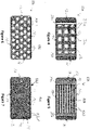
- the first and second pile zones 80 and 82 can be randomly distributed across the terry article 10 such that the height differential between the first and second loops 62 and 72 creates visually perceptible texture across width W and length L of the upper pile component 60.
- the first and second pile zones 80 and 82 can define distinct shapes with respect to each other.
- the first and second pile zones 80 and 82 can be configured to have one or more of a linear, curvilinear, and rectilinear shape.
- Figure 4 illustrates an alternative embodiment of a terry article 11a that includes a first pile zone 81a that surrounds multiple square shaped second zones 82a.
- an alternative embodiment of a terry article 11b includes rectilinear shaped first pile zones 81b and rectilinear shaped second zones 82b.
- a terry article 11c includes a first pile zone 81b that surrounds circular shaped second zones 82b.
- an alternative embodiment of a terry article 11d includes a plurality of curvilinear shaped bands that define the first pile zones 81d and curvilinear narrow bands that define second zones 82d.
- the first pile yarns 64 define the first plurality of loops.
- the first pile yarns 64 may include natural fibers.
- the natural fibers in the first pile yarns 64 can be cotton, flax, bamboo, hemp, or other natural fibers with improved moisture absorbency and retention properties.
- the natural fibers are cotton fibers.
- the first pile yarn can be a ring spun yarn, an open end yarn, a rotor spun yarn, or the Hygrocotton ® brand yarn in accordance with the 075 patent.
- the first pile yarns 64 may have a count between about 984 Dtex (6 Ne) to about 98 Dtex (60 Ne).
- the first pile yarns 64 may have a count between 591 Dtex (10 Ne) to about 118 Dtex (50 Ne), and preferably between about 591 Dtex (10 Ne) to about 197 Dtex (30 Ne). In another example, the first pile yarns 64 may have a count between 197 Dtex (10 Ne) to about 246 Dtex (24 Ne). In one example, the first pile yarns 64 have a count of about 369 Dex (16 Ne). In another example, the first pile yarns 64 have a count of about 295 Dtex (20 Ne). In another example, the first pile yarns 64 have a count of about 246 Dtex (24 Ne). Furthermore, the first pile yarns 64 can have between about 150 and 350 turns/meter of twist, preferably between about 200 to about 300 turns/meter of twist.
- first pile yarns 64 can be plied yarns.
- first pile yarn is 2-ply yarn.
- first pile yarns 64 are 3-ply yarns.
- first pile yarns 64 are 4-ply yarns.
- the second pile yarns 74 include continuous filament thermoplastic yarns and define the second loops.
- the continuous filament yarns may include PET filaments, PLA filaments, PP filaments, or other filaments formed from thermoplastic polymers.
- the continuous filament yarns are non-heatset yarns. Because the fiber morphology and stresses have not been fixed due to heat set processing prior to fabric formation, subsequent exposure of the continuous filament yarns in pile components to a temperature that exceeds the polymer glass transition temperature (Tg) causes the filaments to shrink along filament length and possibly radially. This in turn causes the second pile height H2 (the second pile loops) to decrease relative to the pile height H1 of the first pile loops.
- Tg polymer glass transition temperature
- the continuous filament thermoplastic yarns have a count between about 295 Dtex (75) denier to about 1333 Dtex (1200 denier). In another example, the continuous filament thermoplastic yarns have a count between about 189 Dtex (170 denier) to about 589 (530), and preferably between about 222 Dtex (200 denier) to about 444 Dtex (400 denier). In one example, the continuous filament yarns have a count of about 247 Dtex (220) denier. In another example, the continuous filament yarn has a count of about 300 Dtex (270 denier). In another example, the continuous filament yarn has a count of about 367 Dtex (330) denier.
- the terry article 10 can also include the lower pile component 160.
- the lower pile component 160 is sometimes referred to as the second pile component.
- the lower pile component 160 includes a lower first plurality of pile loops 162 that extends away from the ground component 30 in the second direction 8b.
- the lower first plurality of pile loops 162 are formed by a first set of pile yarns 164, which are similar to the first pile yarns 64 that form pile loops 62 in the upper pile component 60.
- the first plurality of pile loops 162 further define a base 166 located at the ground component 30, a pile end 168 spaced apart from the base 166 along a respective pile loop 162, and a third pile height H3 that extends from the base 166 to the pile end 168.
- the third pile height H3 may be referred to as lower first pile height H3.
- the lower pile component 160 also includes a lower second plurality of pile loops 172 that project away from the ground component 30 in the second direction 8b.
- the second plurality of pile loops 172 are formed from a set of continuous filament thermoplastic yarns 174 which are similar the continuous filament yarns 74 that form loops 72 in the upper pile component 60.
- the second plurality of pile loops 172 include a pile base 176 at the ground component 30, a pile end 178 spaced apart from the pile base 176, and a fourth pile height H4 that extends from the pile base 176 to the pile end 178.
- the fourth pile height referred to as the lower second pile height H4.
- the lower pile component 160 is configured such that the fourth pile height H4 is less than the third pile height H4 as a result of thermally induced shrinkage of the continuous filament thermoplastic yarns 174.
- the lower second pile height H4 is at least 15 % less than the lower first pile height H3.
- the lower second pile height H4 is between about 15% to about 50% less than the lower first pile height H3.
- the lower second pile height H4 is between about 20 % to about 40% less than the lower first pile height H3. In another example, the lower second pile height H4 is between is about 20% less than the lower first pile height H3. In yet another example, the lower second pile height H4 is between is about 30% less than the lower first pile height H3. In yet another example, the lower second pile height H4 is about 40% less than the lower first pile height H3.
- the lower pile component 160 can also include or more first pile zones 180 that include the lower first pile loops 162, and one or more second pile zones 182 that include the lower second pile loops 172.
- the first and second pile zones 180 and 182 can be randomly distributed across the terry article 10 such that the height differential between the lower first and second pile loops 162 and 172 creates a visually perceptible texture across width W and length L of the lower pile component 160.
- the first and second pile zones 180 and 182 can define distinct shapes with respect to each other.
- the pile zones 180 and 182 can define one or more of linear, curvilinear, and rectilinear shapes.
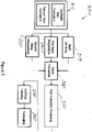
- a method of making a terry article according to an embodiment of the disclosure is illustrated in Figure 8 .
- the method 200 includes yarn formation processing steps 210 for: a) ground warp yarns, b) weft yarns, c) the first pile warp yarns, and d) the second pile warp yarns.
- yarn formation 210 can includes forming additional first and second pile yarn sets for the lower pile component 160. Exemplary yarn formation phases will be described next.
- the ground warp yarns may be formed from any number of fiber types.
- the ground warp yarns can be formed primarily with natural fibers, natural and synthetic blended fibers, and synthetic fibers or yarns with good moisture absorbency and/or retention properties, as described above.
- the ground warp yarns are formed primarily from natural fibers, such as cotton.
- Yarn formation 210 for the ground warp yarns can include various staple yarn spinning systems. Such yarn spinning systems may include bale opening, carding, optionally combing, drafting, roving, and yarn spinning (yarn spinning processes are not illustrated) to the desired count and twist level. In some cases, the ground warp yarns can be plied into 2-ply, 3-ply, or 4-ply configurations. After yarn spinning, the ground warp yarns are wound into the desired yarn packages for ground warp preparation step 220. In one example, ring spinning is the preferred spinning system. However, the ground warp yarns can be formed using open end spinning systems or rotor spun spinning systems. Furthermore, the spinning system may include methods to form the Hygrocotton ® , as disclosed in the 075 patent. The 075 patent is incorporated by reference into present disclosure.
- the weft yarns may be formed with similar fiber types and using the same or similar yarn spinning systems used to form the ground warp yarns. As needed the weft yarns may be plied in 2-ply, 3 ply, or 4-ply configurations. Following weft yarn spinning, the weft yarns are wound onto desired packages. The wound packages are then staged for weft insertion during fabric formation steps discussed further below.
- Yarn formation step 210 includes forming the upper first pile yarns 64 from natural fibers using typical yarn spinning systems.
- the first pile yarns 64 may formed using the same or similar process to how the warp yarns were formed.
- the natural fibers are cotton fibers.
- the first pile yarn formation steps produces pile yarns with a desired count and twist level as described above. However, it should be appreciated that the first pile yarn count and twist level can vary as needed based on the specific end use.
- First pile yarn formation steps may include plying the yarns into 2-ply, 3-ply, or 4-ply configurations.
- the first pile yarns 64 can be formed from blends of cotton and synthetic fibers, such as PET fibers.
- the first pile yarns 64 are formed using other fibers, such as viscose rayon.
- the second pile yarns 74 are formed via continuous filament yarn formation systems.
- polymer resins such as PET, PLA, and PP
- Tm polymer melting temperature
- the filaments may be slightly tensioned by passing over one or more godets before being wound onto a desired yarn packages. Additional bulking or texturizing steps may be included to increase the bulk and impart "false twist" to the yarns.
- the continuous filament yarns 74 are not subjected to extensive heat drawing and tension during yarn formation so that the resulting filaments are not heat set (or heat set via subsequent steps prior to fabric formation).
- the second pile yarns 74 are sometimes referred to as non-heatset yarns.
- Non-heatset yarns can shrink if exposed to temperatures at or above the respective polymer glass transition temperature (Tg), in absence of tension applied to the yarns.
- Tg polymer glass transition temperature
- utilization of non-heatset yarns 74 to form the second pile loops and the subsequent exposure to sufficient thermal energy causes the second pile loops 72 to shrink and reduce the pile height H2, as further detailed below.
- Continuous filament formation steps result in continuous filament yarns 74 with the desired counts as described above.
- the yarn formation step 210 may include forming lower first and second lower pile yarns, in addition to the steps of forming upper first and second pile yarns 64 and 74. Forming lower first and second pile yarns is similar to the production steps in forming the first pile yarns 64 and the second pile yarns 74.
- the ground warp preparation step 220 includes one or more ground warping steps, whereby the ground yarn ends are removed from their respective yarn packages, arranged in a parallel form, and wound onto a ground warp beam.
- the ground warp preparation step 220 also includes a sizing step where a typical sizing agent is applied to each ground warp yarn to aid in fabric formation.
- the ground warp preparation step 220 results in a warp beam of ground warp yarns prepared for weaving.
- the ground warp beam can be positioned on a mounting arm of a weaving loom so that the ground warp yarns can be drawn through the loom components, as further described below.
- the pile warp preparation step 230 includes similar steps to the ground warp preparation steps--warping and sizing.
- pile warp preparation 230 includes warping and sizing the first pile yarns 64 (e.g. the natural fiber pile yarns).
- the pile warp preparation step 230 also includes warping and sizing a second pile warp of the continuous filament thermoplastic yarns 74 (i.e. the non-heatset yarns).
- the pile warp preparation step 230 results in at least two different pile warp beams: a first pile warp beam and a second pile warp beam.
- the pile warp preparation 230 step includes preparing four separate pile warp beams: two upper pile warp beams and two lower pile warp beams. More specifically, the pile warp preparation step 230 can include preparing warp of first pile yarns 64, e.g. natural fiber yarns. The pile preparation step 230 also includes preparing a warp of continuous filament thermoplastic yarns 74. The pile preparation step 230 also included preparing a lower first pile warp of yarns. In one example, the lower first pile yarns are natural fiber yarns that are similar to the yarns in the upper first pile warp. The pile preparation step also includes preparing a lower second warp of continuous filament thermoplastic yarns.
- Step 230 results in four pile warp beams, with two upper pile warp beams dedicated to forming the first and second upper loops in the upper pile component 60, and two lower pile warp beams dedicated to forming the first and second lower loops in the lower pile component 160.
- the ground and pile warp beams are positioned on respective mounting arms or mounting brackets proximate the weaving loom (not shown).
- a weaving step 240 forms a pile fabric by forming the ground component 30 and the pile component on one side (or both sides) of the ground component 30 using a weaving loom designed for terry weaving. More specifically, in the weaving step 240, each ground warp yarn and pile warp yarn from the respective warp beams are drawn-in (not shown) through various components of a weaving loom, such as drop wires, heddle eyes attached to a respective harness, reed and reed dents, in a designated order as is known in the art.
- the weaving step 240 proceeds through two phases: a ground component formation phase and a pile component formation phase. Both phases include a particular shedding motion to facilitate interweaving the weft yarns with the ground warp yarns and pile warp yarns to create the desired pile fabric construction.
- shedding motions can include cam shedding, dobby shedding, or jacquard shedding motions, each of which can cause the selective raising and lowering of warp ends to create an open shed for weft insertion.
- the weaving loom may be configured for one type of shedding motion for the ground warp yarns and another type of shedding motion for the pile warp yarns.
- a cam or dobby shedding motion can be used for the ground warp yarns and the jacquard shedding motions can be used for the pile warp yarns.
- a specific reed motion and warp take-off system is utilized to form the pile loops during the pile component phase and such a mechanism using a terry weaving loom is well known and will not be repeated here.
- ground component phase of the weaving step 240 weft yarns are interwoven with the ground warp yarns to define the ground component or ground fabric.
- Exemplary ground fabric woven constructions include: a 1 ⁇ 1 plain weave, 2x1 rib weave, 2x2 rib weave, or 3x1 rib weave. Other woven constructions in the ground fabric are possible as well.
- the ground component formation phase can utilize different weft insertion techniques, including air-jet, rapier, or projectile type weft (fill) insertion techniques.
- the pile component phase of the weaving step 240 includes interweaving the first pile yarns 64 (via the first warp) with the ground warp and weft yarns to create a first set of pile loops that extend away from the ground component along a vertical direction V.
- pick density that is 3 or more times greater than the pick density of adjacent portions of the pile fabric.
- the weaving step 240 can further include weaving one or more selvedge edges along a length L of the pile fabric.
- the weaving step 240 can form pile fabrics having any number of different fabric constructions.
- the pile fabric is formed to result in a 2-pick up to 5-pick (or more) terry weave pattern.
- the pile fabric can have a 1:1 warp order where each ground warp end is followed by a pile warp end across the width of the pile fabric.
- the pile fabric can have a 2:2 warp order a pair of ground warp ends are followed by a pair of pile warp end across the width of the pile fabric.
- the pile fabric can be formed to include between about 15 to about 45 ends/cm, preferably between about 20 and 30 ends/cm.
- the weft or pick density can range between about 10 picks/cm to about 30 picks/cm.
- the pick density is between about 15 picks/cm to about 25 picks/cm.
- the weaving step 240 further includes forming upper pile component 60 on the upper side 32 of the ground component 30 and forming the lower pile component 160 on the lower side 24 of the ground component 30.
- the lower pile component 160 includes a lower first set of pile loops 162 formed from natural fiber yarns and a lower second set pile loops are formed with continuous filament thermoplastic yarns.
- Dyeing and finishing steps 250 include a de-sizing step and a bleaching.
- the method can also include a step of applying one or more dyes to the pile fabric.
- Such a dyeing step may include applying reactive dyes to natural fiber yarns, and cotton yarns in particular. Either batch, semi-continuous, or continuous dyeing system can be used to apply reactive dyes the pile fabric. Other dyes can be used depending on the particular fiber blend. In other embodiments, yarns can be package died (prior to weaving).
- Step 250 includes a finishing step where various chemical agents are added to pile fabric to improve or augment performance characteristics of the terry article.
- the pile fabric can be treated with a hydrophilic agent, such as silicones.
- the finishing step includes application of one or more softeners to the fabric, such as cationic softeners, non-ionic softeners, and silicones.
- the finishing step includes application of an antimicrobial agent to the pile fabric.
- Other dyes can be used depending on the particular fiber blend.
- yarns can be package died (prior to weaving).
- Step 250 includes a finishing step where various chemical agents are added to pile fabric to improve or augment performance characteristics of the terry article.
- the pile fabric can be treated with a hydrophilic agent, such as silicones.
- the finishing step includes application of one or more softeners to the fabric, such as cationic softeners, non-ionic softeners, and silicones.
- the finishing step includes application of an antimicrobial agent to the pile fabric.
- a thermal treatment step 260 causes the continuous filament thermoplastic yarns, i.e. the non-heatset yarns, in respective pile components 60 and 160 to shrink. Shrinkage of the continuous filament thermoplastic yarns decreases a pile height of the second plurality of pile loops relative to the pile height of the first plurality of pile loops.
- the thermal treatment step 260 includes advancing the pile fabric through a heating machine that exposes the pile fabric to thermal energy for a period of time that is sufficient to induce shrinkage in the non-heat set yarns. The thermal energy is sufficient to expose the pile fabric to a temperature that is greater than or equal to the glass transition temperature (Tg) of the continuous filament thermoplastic yarn.
- the surface temperature of the pile fabric during the thermal treatment step 260 approaches or exceeds the glass transition temperature (Tg) of the continuous filament thermoplastic yarns.
- Tg glass transition temperature
- the glass transition temperature (Tg) is between about 67 to 81 degrees Celsius.
- the glass transition temperature (Tg) is between about 60 to 65 degrees Celsius.
- the pile fabrics are exposed to temperature between about 100 and to 130 degrees Celsius. Accordingly, the desired surface temperature of the pile fabric should fall within or exceed somewhat the stated ranges for each of the fibers mention above.
- any suitable thermal treatment can be used, such as, convection, steam, or infrared thermal treatments.
- the heating machine can include a convection oven, a steam oven, or an infrared oven.
- the pile fabric is exposed to the desired thermal energy levels for a period of time that is sufficient to induce shrinkage in the non-heatset pile yarns.
- the exposure time is dependent on the dwell time of pile fabric within the heating machine, which is related to the machine speed and length of the heating zones within the heating machine.
- the pile fabric is advanced through the heating machine at a rate that ranges between 2.0 meters/min up to about 30 meters/min, which varies based on number heating zones.
- the method includes a cutting step 270 where the pile fabric is cut to size of one or more terry articles, such as bath towel, a hand towel, and a washcloth. Following cutting 270, additional edge binding or hems can be applied to finish the cut edges. After the cutting step, a packing step 280 places the finished terry articles in suitable packaging for shipment.
- a cutting step 270 where the pile fabric is cut to size of one or more terry articles, such as bath towel, a hand towel, and a washcloth.
- additional edge binding or hems can be applied to finish the cut edges.
- a packing step 280 places the finished terry articles in suitable packaging for shipment.
Claims (13)
- Article en tissu éponge (10) comprenant :un élément de fond (30) comportant une pluralité de fils de chaîne de fond (40) et une pluralité de fils de trame (42) entrelacés avec la pluralité de fils de chaîne de fond, dans lequel les fils de trame et les fils de chaîne de fond comprennent chacun au moins une fibre naturelle et une fibre synthétique, l'élément de fond comportant un côté inférieur (34) et un côté supérieur (32) opposé au côté inférieur le long d'une direction verticale (6) ; etun élément de poil comportant 1) une première pluralité de bouclettes (62) qui s'étendent à partir de l'élément de fond le long de la direction verticale, la première pluralité de bouclettes étant formée à partir d'un premier ensemble de fils de poil (64) composés de fibres naturelles, la première pluralité de bouclettes comportant une première base de poil (66) située au niveau de l'élément de fond, une première extrémité de poil (68) espacée de la première base de poil, et une première hauteur de poil (H1) qui s'étend de la première base de poil à la première extrémité de poil le long de la direction verticale, et 2) une seconde pluralité de bouclettes (72) qui s'étendent à l'écart de l'élément de fond dans la direction verticale, la seconde pluralité de bouclettes étant formée d'un ensemble de fils thermoplastiques à filaments continus (74), la seconde pluralité de bouclettes comportant une seconde base de poil (76) au niveau de l'élément de fond, une seconde extrémité de poil espacée de la seconde base de poil et une seconde hauteur de poil (H2) qui s'étend de la seconde base de poil à la seconde extrémité de poil (78) le long de la direction verticale, la seconde hauteur de poil étant inférieure à la première hauteur de poil, l'article caractérisé en ce que l'article présente une surface en partie formée par la seconde hauteur de poil (H2) dont les extrémités (78) sont rétractées par rapport au premier ensemble de fils de poil dans les zones 80, 82 et par rapport aux parties restantes du second poil tout en étant maintenues dans une direction verticale vers le haut sensiblement stable les unes par rapport aux autres par une présentation respective sur les fils de chaîne et les fils de trame tissés ensemble.
- Article en tissu éponge selon la revendication 1, dans lequel l'élément de poil est un élément de poil supérieur (60) qui est disposé sur le côté supérieur, dans lequel la première pluralité de bouclettes est une première pluralité supérieure de bouclettes, et la seconde pluralité de bouclettes est une seconde pluralité supérieure de bouclettes.
- Article en tissu éponge selon la revendication 2, comportant en outre un élément de poil inférieur (160) disposé sur le côté inférieur, l'élément de poil inférieur comportant une première pluralité inférieure de bouclettes et une seconde pluralité inférieure de bouclettes, dans lequel la seconde pluralité inférieure de bouclettes est formée de fils thermoplastiques à filaments continus.
- Article en tissu éponge selon la revendication 1, dans lequel la première pluralité de bouclettes est distribuée de manière aléatoire parmi la seconde pluralité de bouclettes sur une dimension de longueur et de largeur de l'élément de poil.
- Article en tissu éponge selon la revendication 1, dans lequel :les premières zones de poil définissent une ou plusieurs formes parmi une forme linéaire, une forme curviligne et une forme rectiligne ; et/oules secondes zones de poil définissent une ou plusieurs formes parmi une forme linéaire, une forme curviligne et une forme rectiligne.
- Article en tissu éponge selon la revendication 1 et une quelconque revendication dépendante de celle-ci, dans lequel les fils thermoplastiques à filaments continus comprennent des filaments thermoplastiques non thermodurcis.
- Article en tissu éponge selon l'une quelconque des revendications 1 et toute revendication qui en dépend, dans lequel les fils thermoplastiques à filaments continus présentent un compte compris entre environ 189 dtex (170 deniers) et environ 589 dtex (530 deniers).
- Article en tissu éponge selon l'une quelconque des revendications 1 et toute autre revendication qui en dépend, dans lequel le premier ensemble de fils de poil présente un compte compris entre environ 984 dtex (6 Ne) et environ 98 dtex (60 Ne).
- Article en tissu éponge selon l'une quelconque des revendications 1 et toute autre revendication qui en dépend, dans lequel la fibre naturelle du premier ensemble de fils de poil est une fibre de coton.
- Procédé de fabrication d'un article en tissu éponge (10) comportant les étapes de :tissage (240) d'un tissu à poil comportant un élément de fond (30) et un élément de poil disposés sur au moins l'un parmi un côté supérieur (60) et un côté inférieur (160) de l'élément de fond, de sorte que l'élément de poil comporte une première pluralité de bouclettes (62) formées à partir de fils de fibres naturelles et un second ensemble de bouclettes (72) formées à partir de fils thermoplastiques à filaments continus ; etaprès l'étape de tissage, le traitement thermique (260) du tissu à poil de sorte que les fils thermoplastiques à filaments continus sont soumis à un réglage de rétraction thermique, diminuant ainsi une hauteur de poil (H2) de la seconde pluralité de bouclettes par rapport à une hauteur de poil (H1) de la première pluralité de bouclettes,le procédé est caractérisé en ce que le réglage de la rétraction thermique est effectué par un traitement thermique de surface sur le tissu à poil de l'article au-dessus de la température de transition vitreuse du fil thermoplastique à filaments continus à une vitesse de 2 à 30 mètres par minute de sorte que les extrémités (78) des seconds poils se rétractent autour de la surface du tissu à poil dans une direction verticale sensiblement vers le haut par rapport au premier ensemble de fils de poil pour faire en sorte que la seconde hauteur de poil soit inférieure à la première hauteur de poil dans la direction sensiblement vers le haut à partir de l'élément de fond sur les fils de chaîne et les fils de trame tissés ensemble de l'élément de fond.
- Procédé selon la revendication 11, les fils thermoplastiques à filaments continus sont des fils non thermofixés, dans lequel l'étape de traitement thermique comporte l'avancement du tissu à poil à travers une machine de chauffage qui expose le tissu à poil à de l'énergie thermique pendant une période de temps qui est suffisante pour induire un rétrécissement dans les fils non thermofixés.
- Procédé selon la revendication 11, dans lequel l'étape de traitement thermique comporte l'exposition du tissu à poil à une température qui est supérieure ou égale à la température de transition vitreuse du fil thermoplastique à filaments continus.
- Procédé selon la revendication 11, dans lequel l'étape de tissage comporte :la formation de l'élément de poil sur le côté supérieur de l'élément de fond ; etla formation d'un second élément de poil sur le côté inférieur de l'élément de fond de sorte que l'élément de poil inférieur comporte une première pluralité inférieure de bouclettes et une seconde pluralité inférieure de bouclettes qui sont formées à partir d'un second ensemble de fils thermoplastiques à filaments continus.
Applications Claiming Priority (2)
| Application Number | Priority Date | Filing Date | Title |
|---|---|---|---|
| IN3474MU2015 | 2015-09-10 | ||
| US14/866,916 US9828704B2 (en) | 2015-09-10 | 2015-09-26 | Terry article with synthetic filament yarns and method of making same |
Publications (3)
| Publication Number | Publication Date |
|---|---|
| EP3141643A2 EP3141643A2 (fr) | 2017-03-15 |
| EP3141643A3 EP3141643A3 (fr) | 2017-03-29 |
| EP3141643B1 true EP3141643B1 (fr) | 2022-06-08 |
Family
ID=56990235
Family Applications (1)
| Application Number | Title | Priority Date | Filing Date |
|---|---|---|---|
| EP16188260.0A Active EP3141643B1 (fr) | 2015-09-10 | 2016-09-12 | Article en tissu eponge comprenant des fils continus synthetiques et son procede de fabrication |
Country Status (5)
| Country | Link |
|---|---|
| EP (1) | EP3141643B1 (fr) |
| DK (1) | DK3141643T3 (fr) |
| ES (1) | ES2926486T3 (fr) |
| PL (1) | PL3141643T3 (fr) |
| PT (1) | PT3141643T (fr) |
Families Citing this family (3)
| Publication number | Priority date | Publication date | Assignee | Title |
|---|---|---|---|---|
| JP6468577B1 (ja) * | 2017-12-28 | 2019-02-13 | 内野株式会社 | パイル織物 |
| CN111455525A (zh) * | 2020-04-13 | 2020-07-28 | 河北瑞春纺织有限公司 | 一种三纬加四纬、七纬仿浮雕毛圈弱捻毛巾及其制备方法 |
| US20220136146A1 (en) * | 2020-10-29 | 2022-05-05 | Welspun India Limited | Terry article and method of making same |
Family Cites Families (2)
| Publication number | Priority date | Publication date | Assignee | Title |
|---|---|---|---|---|
| US3030691A (en) * | 1960-03-17 | 1962-04-24 | Fieldcrest Mills Inc | High-low terry pile fabric and method |
| KR20120138637A (ko) * | 2011-06-15 | 2012-12-26 | 트리콜 재팬 가부시키가이샤 | 파일직물 |
-
2016
- 2016-09-12 ES ES16188260T patent/ES2926486T3/es active Active
- 2016-09-12 PT PT161882600T patent/PT3141643T/pt unknown
- 2016-09-12 EP EP16188260.0A patent/EP3141643B1/fr active Active
- 2016-09-12 DK DK16188260.0T patent/DK3141643T3/da active
- 2016-09-12 PL PL16188260.0T patent/PL3141643T3/pl unknown
Also Published As
| Publication number | Publication date |
|---|---|
| DK3141643T3 (da) | 2022-09-12 |
| EP3141643A2 (fr) | 2017-03-15 |
| ES2926486T3 (es) | 2022-10-26 |
| PL3141643T3 (pl) | 2022-10-03 |
| PT3141643T (pt) | 2022-09-13 |
| EP3141643A3 (fr) | 2017-03-29 |
Similar Documents
| Publication | Publication Date | Title |
|---|---|---|
| US9828704B2 (en) | Terry article with synthetic filament yarns and method of making same | |
| EP3237661B1 (fr) | Tissu éponge tissé à séchage rapide et articles connexes | |
| EP3530786B1 (fr) | Article en tissu éponge à torsion souple | |
| EP3147394A1 (fr) | Écharpe textile et son procédé de fabrication | |
| US20180080151A1 (en) | Performance fabrics and related articles | |
| EP3141643B1 (fr) | Article en tissu eponge comprenant des fils continus synthetiques et son procede de fabrication | |
| CZ83796A3 (en) | Open net-like structure, process of its manufacture and use | |
| EP3147395A1 (fr) | Toile de cambray, linges de lit et procedes de fabrication associes | |
| EP3147396B1 (fr) | Tissu tisse ayant des fils continus gonflants et procedes de production associes | |
| WO2013074539A1 (fr) | Tissu tissé fait de fils retors et procédé de fabrication associé | |
| EP3447179A1 (fr) | Étoffe tissée hydroenchevêtrée | |
| EP3402916B1 (fr) | Procédé de production d'un produit textile | |
| EP2569471B1 (fr) | Procédé de fabrication de tissus pour l'absorbtion d'eau ou d'autres liquides en géneral | |
| EP3992337A1 (fr) | Article en tissu éponge et son procédé de fabrication | |
| EP1826303A1 (fr) | Linge de bain a usage personnel destine notamment au sechage et son procede de fabrication | |
| KR101103681B1 (ko) | 천연소재의 질감을 갖는 폴리에스테르직물 및 그 제조방법 | |
| WO2014064661A2 (fr) | Procédé de fabrication d'un tissu à base de soie imitant un tissu en cachemire | |
| JP5443399B2 (ja) | 浴用タオル | |
| JP4197981B2 (ja) | ストレッチ糸及びストレッチ織編物 | |
| EP3146958A1 (fr) | Oreiller, matériau textile et procédés associés | |
| JP5216974B2 (ja) | 芯鞘型複合糸を用いてなる布帛および衣料 | |
| JP2000248425A (ja) | 高収縮性ポリエステル繊維および製造方法 | |
| US20170088983A1 (en) | Pillow article, textile material, and related methods | |
| JP2004183193A (ja) | 織物 | |
| JP3425668B2 (ja) | 凹凸柄パイル布帛 |
Legal Events
| Date | Code | Title | Description |
|---|---|---|---|
| PUAI | Public reference made under article 153(3) epc to a published international application that has entered the european phase |
Free format text: ORIGINAL CODE: 0009012 |
|
| STAA | Information on the status of an ep patent application or granted ep patent |
Free format text: STATUS: THE APPLICATION HAS BEEN PUBLISHED |
|
| PUAL | Search report despatched |
Free format text: ORIGINAL CODE: 0009013 |
|
| AK | Designated contracting states |
Kind code of ref document: A2 Designated state(s): AL AT BE BG CH CY CZ DE DK EE ES FI FR GB GR HR HU IE IS IT LI LT LU LV MC MK MT NL NO PL PT RO RS SE SI SK SM TR |
|
| AX | Request for extension of the european patent |
Extension state: BA ME |
|
| AK | Designated contracting states |
Kind code of ref document: A3 Designated state(s): AL AT BE BG CH CY CZ DE DK EE ES FI FR GB GR HR HU IE IS IT LI LT LU LV MC MK MT NL NO PL PT RO RS SE SI SK SM TR |
|
| AX | Request for extension of the european patent |
Extension state: BA ME |
|
| RIC1 | Information provided on ipc code assigned before grant |
Ipc: D03D 27/08 20060101AFI20170221BHEP Ipc: D03D 15/04 20060101ALI20170221BHEP |
|
| STAA | Information on the status of an ep patent application or granted ep patent |
Free format text: STATUS: REQUEST FOR EXAMINATION WAS MADE |
|
| 17P | Request for examination filed |
Effective date: 20170929 |
|
| RBV | Designated contracting states (corrected) |
Designated state(s): AL AT BE BG CH CY CZ DE DK EE ES FI FR GB GR HR HU IE IS IT LI LT LU LV MC MK MT NL NO PL PT RO RS SE SI SK SM TR |
|
| STAA | Information on the status of an ep patent application or granted ep patent |
Free format text: STATUS: EXAMINATION IS IN PROGRESS |
|
| 17Q | First examination report despatched |
Effective date: 20190809 |
|
| STAA | Information on the status of an ep patent application or granted ep patent |
Free format text: STATUS: EXAMINATION IS IN PROGRESS |
|
| REG | Reference to a national code |
Ref country code: DE Ref legal event code: R079 Ref document number: 602016072654 Country of ref document: DE Free format text: PREVIOUS MAIN CLASS: D03D0027080000 Ipc: D03D0015567000 |
|
| GRAP | Despatch of communication of intention to grant a patent |
Free format text: ORIGINAL CODE: EPIDOSNIGR1 |
|
| STAA | Information on the status of an ep patent application or granted ep patent |
Free format text: STATUS: GRANT OF PATENT IS INTENDED |
|
| RIC1 | Information provided on ipc code assigned before grant |
Ipc: D03D 27/08 20060101ALI20211029BHEP Ipc: D03D 15/567 20210101AFI20211029BHEP |
|
| INTG | Intention to grant announced |
Effective date: 20211207 |
|
| GRAS | Grant fee paid |
Free format text: ORIGINAL CODE: EPIDOSNIGR3 |
|
| GRAA | (expected) grant |
Free format text: ORIGINAL CODE: 0009210 |
|
| STAA | Information on the status of an ep patent application or granted ep patent |
Free format text: STATUS: THE PATENT HAS BEEN GRANTED |
|
| AK | Designated contracting states |
Kind code of ref document: B1 Designated state(s): AL AT BE BG CH CY CZ DE DK EE ES FI FR GB GR HR HU IE IS IT LI LT LU LV MC MK MT NL NO PL PT RO RS SE SI SK SM TR |
|
| REG | Reference to a national code |
Ref country code: GB Ref legal event code: FG4D |
|
| REG | Reference to a national code |
Ref country code: AT Ref legal event code: REF Ref document number: 1496987 Country of ref document: AT Kind code of ref document: T Effective date: 20220615 Ref country code: CH Ref legal event code: EP |
|
| REG | Reference to a national code |
Ref country code: DE Ref legal event code: R096 Ref document number: 602016072654 Country of ref document: DE |
|
| REG | Reference to a national code |
Ref country code: IE Ref legal event code: FG4D |
|
| REG | Reference to a national code |
Ref country code: DK Ref legal event code: T3 Effective date: 20220907 |
|
| REG | Reference to a national code |
Ref country code: PT Ref legal event code: SC4A Ref document number: 3141643 Country of ref document: PT Date of ref document: 20220913 Kind code of ref document: T Free format text: AVAILABILITY OF NATIONAL TRANSLATION Effective date: 20220906 |
|
| REG | Reference to a national code |
Ref country code: NL Ref legal event code: FP |
|
| REG | Reference to a national code |
Ref country code: LT Ref legal event code: MG9D |
|
| REG | Reference to a national code |
Ref country code: SE Ref legal event code: TRGR |
|
| REG | Reference to a national code |
Ref country code: ES Ref legal event code: FG2A Ref document number: 2926486 Country of ref document: ES Kind code of ref document: T3 Effective date: 20221026 |
|
| PG25 | Lapsed in a contracting state [announced via postgrant information from national office to epo] |
Ref country code: NO Free format text: LAPSE BECAUSE OF FAILURE TO SUBMIT A TRANSLATION OF THE DESCRIPTION OR TO PAY THE FEE WITHIN THE PRESCRIBED TIME-LIMIT Effective date: 20220908 Ref country code: LT Free format text: LAPSE BECAUSE OF FAILURE TO SUBMIT A TRANSLATION OF THE DESCRIPTION OR TO PAY THE FEE WITHIN THE PRESCRIBED TIME-LIMIT Effective date: 20220608 Ref country code: HR Free format text: LAPSE BECAUSE OF FAILURE TO SUBMIT A TRANSLATION OF THE DESCRIPTION OR TO PAY THE FEE WITHIN THE PRESCRIBED TIME-LIMIT Effective date: 20220608 Ref country code: GR Free format text: LAPSE BECAUSE OF FAILURE TO SUBMIT A TRANSLATION OF THE DESCRIPTION OR TO PAY THE FEE WITHIN THE PRESCRIBED TIME-LIMIT Effective date: 20220909 Ref country code: FI Free format text: LAPSE BECAUSE OF FAILURE TO SUBMIT A TRANSLATION OF THE DESCRIPTION OR TO PAY THE FEE WITHIN THE PRESCRIBED TIME-LIMIT Effective date: 20220608 Ref country code: BG Free format text: LAPSE BECAUSE OF FAILURE TO SUBMIT A TRANSLATION OF THE DESCRIPTION OR TO PAY THE FEE WITHIN THE PRESCRIBED TIME-LIMIT Effective date: 20220908 |
|
| PG25 | Lapsed in a contracting state [announced via postgrant information from national office to epo] |
Ref country code: RS Free format text: LAPSE BECAUSE OF FAILURE TO SUBMIT A TRANSLATION OF THE DESCRIPTION OR TO PAY THE FEE WITHIN THE PRESCRIBED TIME-LIMIT Effective date: 20220608 Ref country code: LV Free format text: LAPSE BECAUSE OF FAILURE TO SUBMIT A TRANSLATION OF THE DESCRIPTION OR TO PAY THE FEE WITHIN THE PRESCRIBED TIME-LIMIT Effective date: 20220608 |
|
| PG25 | Lapsed in a contracting state [announced via postgrant information from national office to epo] |
Ref country code: SM Free format text: LAPSE BECAUSE OF FAILURE TO SUBMIT A TRANSLATION OF THE DESCRIPTION OR TO PAY THE FEE WITHIN THE PRESCRIBED TIME-LIMIT Effective date: 20220608 Ref country code: SK Free format text: LAPSE BECAUSE OF FAILURE TO SUBMIT A TRANSLATION OF THE DESCRIPTION OR TO PAY THE FEE WITHIN THE PRESCRIBED TIME-LIMIT Effective date: 20220608 Ref country code: RO Free format text: LAPSE BECAUSE OF FAILURE TO SUBMIT A TRANSLATION OF THE DESCRIPTION OR TO PAY THE FEE WITHIN THE PRESCRIBED TIME-LIMIT Effective date: 20220608 Ref country code: EE Free format text: LAPSE BECAUSE OF FAILURE TO SUBMIT A TRANSLATION OF THE DESCRIPTION OR TO PAY THE FEE WITHIN THE PRESCRIBED TIME-LIMIT Effective date: 20220608 Ref country code: CZ Free format text: LAPSE BECAUSE OF FAILURE TO SUBMIT A TRANSLATION OF THE DESCRIPTION OR TO PAY THE FEE WITHIN THE PRESCRIBED TIME-LIMIT Effective date: 20220608 |
|
| PG25 | Lapsed in a contracting state [announced via postgrant information from national office to epo] |
Ref country code: IS Free format text: LAPSE BECAUSE OF FAILURE TO SUBMIT A TRANSLATION OF THE DESCRIPTION OR TO PAY THE FEE WITHIN THE PRESCRIBED TIME-LIMIT Effective date: 20221008 |
|
| REG | Reference to a national code |
Ref country code: DE Ref legal event code: R097 Ref document number: 602016072654 Country of ref document: DE |
|
| PG25 | Lapsed in a contracting state [announced via postgrant information from national office to epo] |
Ref country code: AL Free format text: LAPSE BECAUSE OF FAILURE TO SUBMIT A TRANSLATION OF THE DESCRIPTION OR TO PAY THE FEE WITHIN THE PRESCRIBED TIME-LIMIT Effective date: 20220608 |
|
| PLBE | No opposition filed within time limit |
Free format text: ORIGINAL CODE: 0009261 |
|
| STAA | Information on the status of an ep patent application or granted ep patent |
Free format text: STATUS: NO OPPOSITION FILED WITHIN TIME LIMIT |
|
| PG25 | Lapsed in a contracting state [announced via postgrant information from national office to epo] |
Ref country code: MC Free format text: LAPSE BECAUSE OF FAILURE TO SUBMIT A TRANSLATION OF THE DESCRIPTION OR TO PAY THE FEE WITHIN THE PRESCRIBED TIME-LIMIT Effective date: 20220608 |
|
| REG | Reference to a national code |
Ref country code: CH Ref legal event code: PL |
|
| 26N | No opposition filed |
Effective date: 20230310 |
|
| PG25 | Lapsed in a contracting state [announced via postgrant information from national office to epo] |
Ref country code: SI Free format text: LAPSE BECAUSE OF FAILURE TO SUBMIT A TRANSLATION OF THE DESCRIPTION OR TO PAY THE FEE WITHIN THE PRESCRIBED TIME-LIMIT Effective date: 20220608 |
|
| PG25 | Lapsed in a contracting state [announced via postgrant information from national office to epo] |
Ref country code: LU Free format text: LAPSE BECAUSE OF NON-PAYMENT OF DUE FEES Effective date: 20220912 |
|
| PG25 | Lapsed in a contracting state [announced via postgrant information from national office to epo] |
Ref country code: LI Free format text: LAPSE BECAUSE OF NON-PAYMENT OF DUE FEES Effective date: 20220930 Ref country code: IE Free format text: LAPSE BECAUSE OF NON-PAYMENT OF DUE FEES Effective date: 20220912 Ref country code: CH Free format text: LAPSE BECAUSE OF NON-PAYMENT OF DUE FEES Effective date: 20220930 |
|
| PGFP | Annual fee paid to national office [announced via postgrant information from national office to epo] |
Ref country code: NL Payment date: 20230914 Year of fee payment: 8 Ref country code: IT Payment date: 20230912 Year of fee payment: 8 Ref country code: GB Payment date: 20230912 Year of fee payment: 8 Ref country code: AT Payment date: 20230922 Year of fee payment: 8 |
|
| PGFP | Annual fee paid to national office [announced via postgrant information from national office to epo] |
Ref country code: SE Payment date: 20230904 Year of fee payment: 8 Ref country code: PT Payment date: 20230831 Year of fee payment: 8 Ref country code: PL Payment date: 20230911 Year of fee payment: 8 Ref country code: FR Payment date: 20230904 Year of fee payment: 8 Ref country code: DK Payment date: 20230919 Year of fee payment: 8 Ref country code: DE Payment date: 20230912 Year of fee payment: 8 Ref country code: BE Payment date: 20230919 Year of fee payment: 8 |
|
| PGFP | Annual fee paid to national office [announced via postgrant information from national office to epo] |
Ref country code: ES Payment date: 20231011 Year of fee payment: 8 |
|
| PG25 | Lapsed in a contracting state [announced via postgrant information from national office to epo] |
Ref country code: HU Free format text: LAPSE BECAUSE OF FAILURE TO SUBMIT A TRANSLATION OF THE DESCRIPTION OR TO PAY THE FEE WITHIN THE PRESCRIBED TIME-LIMIT; INVALID AB INITIO Effective date: 20160912 |