EP3140228B1 - Magnetische aufstellvorrichtung für dosenzargen - Google Patents
Magnetische aufstellvorrichtung für dosenzargen Download PDFInfo
- Publication number
- EP3140228B1 EP3140228B1 EP15711416.6A EP15711416A EP3140228B1 EP 3140228 B1 EP3140228 B1 EP 3140228B1 EP 15711416 A EP15711416 A EP 15711416A EP 3140228 B1 EP3140228 B1 EP 3140228B1
- Authority
- EP
- European Patent Office
- Prior art keywords
- magnet arrangement
- transport device
- lying
- bodies
- magnetic body
- Prior art date
- Legal status (The legal status is an assumption and is not a legal conclusion. Google has not performed a legal analysis and makes no representation as to the accuracy of the status listed.)
- Active
Links
Images

Classifications
-
- B—PERFORMING OPERATIONS; TRANSPORTING
- B65—CONVEYING; PACKING; STORING; HANDLING THIN OR FILAMENTARY MATERIAL
- B65G—TRANSPORT OR STORAGE DEVICES, e.g. CONVEYORS FOR LOADING OR TIPPING, SHOP CONVEYOR SYSTEMS OR PNEUMATIC TUBE CONVEYORS
- B65G15/00—Conveyors having endless load-conveying surfaces, i.e. belts and like continuous members, to which tractive effort is transmitted by means other than endless driving elements of similar configuration
- B65G15/30—Belts or like endless load-carriers
- B65G15/58—Belts or like endless load-carriers with means for holding or retaining the loads in fixed position, e.g. magnetic
-
- B—PERFORMING OPERATIONS; TRANSPORTING
- B65—CONVEYING; PACKING; STORING; HANDLING THIN OR FILAMENTARY MATERIAL
- B65G—TRANSPORT OR STORAGE DEVICES, e.g. CONVEYORS FOR LOADING OR TIPPING, SHOP CONVEYOR SYSTEMS OR PNEUMATIC TUBE CONVEYORS
- B65G15/00—Conveyors having endless load-conveying surfaces, i.e. belts and like continuous members, to which tractive effort is transmitted by means other than endless driving elements of similar configuration
- B65G15/10—Conveyors having endless load-conveying surfaces, i.e. belts and like continuous members, to which tractive effort is transmitted by means other than endless driving elements of similar configuration comprising two or more co-operating endless surfaces with parallel longitudinal axes, or a multiplicity of parallel elements, e.g. ropes defining an endless surface
- B65G15/105—Conveyors having endless load-conveying surfaces, i.e. belts and like continuous members, to which tractive effort is transmitted by means other than endless driving elements of similar configuration comprising two or more co-operating endless surfaces with parallel longitudinal axes, or a multiplicity of parallel elements, e.g. ropes defining an endless surface the surface being formed by two or more ropes
-
- B—PERFORMING OPERATIONS; TRANSPORTING
- B65—CONVEYING; PACKING; STORING; HANDLING THIN OR FILAMENTARY MATERIAL
- B65G—TRANSPORT OR STORAGE DEVICES, e.g. CONVEYORS FOR LOADING OR TIPPING, SHOP CONVEYOR SYSTEMS OR PNEUMATIC TUBE CONVEYORS
- B65G21/00—Supporting or protective framework or housings for endless load-carriers or traction elements of belt or chain conveyors
- B65G21/20—Means incorporated in, or attached to, framework or housings for guiding load-carriers, traction elements or loads supported on moving surfaces
- B65G21/2009—Magnetic retaining means
-
- B—PERFORMING OPERATIONS; TRANSPORTING
- B65—CONVEYING; PACKING; STORING; HANDLING THIN OR FILAMENTARY MATERIAL
- B65G—TRANSPORT OR STORAGE DEVICES, e.g. CONVEYORS FOR LOADING OR TIPPING, SHOP CONVEYOR SYSTEMS OR PNEUMATIC TUBE CONVEYORS
- B65G21/00—Supporting or protective framework or housings for endless load-carriers or traction elements of belt or chain conveyors
- B65G21/20—Means incorporated in, or attached to, framework or housings for guiding load-carriers, traction elements or loads supported on moving surfaces
- B65G21/2009—Magnetic retaining means
- B65G21/2018—Magnetic retaining means for retaining the load on the load-carrying surface
-
- B—PERFORMING OPERATIONS; TRANSPORTING
- B65—CONVEYING; PACKING; STORING; HANDLING THIN OR FILAMENTARY MATERIAL
- B65G—TRANSPORT OR STORAGE DEVICES, e.g. CONVEYORS FOR LOADING OR TIPPING, SHOP CONVEYOR SYSTEMS OR PNEUMATIC TUBE CONVEYORS
- B65G47/00—Article or material-handling devices associated with conveyors; Methods employing such devices
- B65G47/22—Devices influencing the relative position or the attitude of articles during transit by conveyors
- B65G47/24—Devices influencing the relative position or the attitude of articles during transit by conveyors orientating the articles
-
- B—PERFORMING OPERATIONS; TRANSPORTING
- B65—CONVEYING; PACKING; STORING; HANDLING THIN OR FILAMENTARY MATERIAL
- B65G—TRANSPORT OR STORAGE DEVICES, e.g. CONVEYORS FOR LOADING OR TIPPING, SHOP CONVEYOR SYSTEMS OR PNEUMATIC TUBE CONVEYORS
- B65G47/00—Article or material-handling devices associated with conveyors; Methods employing such devices
- B65G47/22—Devices influencing the relative position or the attitude of articles during transit by conveyors
- B65G47/24—Devices influencing the relative position or the attitude of articles during transit by conveyors orientating the articles
- B65G47/244—Devices influencing the relative position or the attitude of articles during transit by conveyors orientating the articles by turning them about an axis substantially perpendicular to the conveying plane
- B65G47/2445—Devices influencing the relative position or the attitude of articles during transit by conveyors orientating the articles by turning them about an axis substantially perpendicular to the conveying plane by means of at least two co-operating endless conveying elements
-
- B—PERFORMING OPERATIONS; TRANSPORTING
- B65—CONVEYING; PACKING; STORING; HANDLING THIN OR FILAMENTARY MATERIAL
- B65G—TRANSPORT OR STORAGE DEVICES, e.g. CONVEYORS FOR LOADING OR TIPPING, SHOP CONVEYOR SYSTEMS OR PNEUMATIC TUBE CONVEYORS
- B65G47/00—Article or material-handling devices associated with conveyors; Methods employing such devices
- B65G47/22—Devices influencing the relative position or the attitude of articles during transit by conveyors
- B65G47/24—Devices influencing the relative position or the attitude of articles during transit by conveyors orientating the articles
- B65G47/248—Devices influencing the relative position or the attitude of articles during transit by conveyors orientating the articles by turning over or inverting them
- B65G47/252—Devices influencing the relative position or the attitude of articles during transit by conveyors orientating the articles by turning over or inverting them about an axis substantially perpendicular to the conveying direction
-
- B—PERFORMING OPERATIONS; TRANSPORTING
- B65—CONVEYING; PACKING; STORING; HANDLING THIN OR FILAMENTARY MATERIAL
- B65G—TRANSPORT OR STORAGE DEVICES, e.g. CONVEYORS FOR LOADING OR TIPPING, SHOP CONVEYOR SYSTEMS OR PNEUMATIC TUBE CONVEYORS
- B65G47/00—Article or material-handling devices associated with conveyors; Methods employing such devices
- B65G47/34—Devices for discharging articles or materials from conveyor
- B65G47/36—Devices for discharging articles or materials from conveyor by detaching suspended articles
-
- B—PERFORMING OPERATIONS; TRANSPORTING
- B65—CONVEYING; PACKING; STORING; HANDLING THIN OR FILAMENTARY MATERIAL
- B65G—TRANSPORT OR STORAGE DEVICES, e.g. CONVEYORS FOR LOADING OR TIPPING, SHOP CONVEYOR SYSTEMS OR PNEUMATIC TUBE CONVEYORS
- B65G2201/00—Indexing codes relating to handling devices, e.g. conveyors, characterised by the type of product or load being conveyed or handled
- B65G2201/02—Articles
- B65G2201/0235—Containers
- B65G2201/0252—Cans
Definitions
- the invention relates to a magnetic Zargenaufstellvortechnisch according to the preamble of claim 1, an apparatus for the production of cans with such Zargenaufstellvortechnisch and a use of such Zargenaufstellvortechnisch.
- a set-up device is a magnetic frame display by OS Walker Magnetics, USA.
- OS Walker Magnetics USA.
- this Zargenetzsteller the frame over the leading edge or the leading edge turned or tilted, so that the frame is placed with her back.
- With the help of two magnetic boxes on both sides of the conveyor path of the frames the frame is centered, which reduces the risk of scratches on the frame varnish.
- This solution works for a variety of frame diameters and heights and is thus a universal solution that sets up the frames with their rumps.
- a disadvantage is that there is an increased risk of contacting the magnetic boxes with the transported frames, which can lead to damage of the frames. Furthermore, such magnetic boxes can be difficult to assemble and adjust. In connection with this they bring the disadvantage that the insight into the Inside the device is blocked by their location, so that access to the device is difficult. Furthermore, the trajectory or the erection process of the frames can not or hardly be observed, so that make readjustments of the device difficult.
- the international patent application WO 2014/043821 A1 discloses a magnetic bezel erector according to claim 1. This comprises a first transport means for lying can bodies and a second transport means for erected can bodies. The can bodies can be placed either with their rear part or with their front part.
- the magnetic frame erector comprises an infeed conveyor for conveying horizontal frames, a transport means arranged above the infeed conveyor for conveying erected frames suspended from the conveyor, and a controller.
- a first magnet arrangement controllably activatable and deactivatable by the controller is arranged below the intake transport device such that a frame lying on the intake transport device can be releasably magnetically held on the intake transport device.
- a second magnet arrangement is arranged above a region of the inlet transport device in which the frames are transported and designed such that a frame lying on the inlet transport device can be raised by means of the magnetic field of the second magnet arrangement with the magnetic field of the first magnet arrangement deactivated.
- a third magnet arrangement is provided above the transport device and configured and arranged such that a raised frame can be raised further and lifted off from the intake transport device and can be transported to the transport device in a magnetically suspended position.
- the controller is configured to activate the first magnet assembly when a leading edge of one on the Infeed conveyor lying chime the second magnet arrangement happens and to deactivate the first magnet arrangement when a trailing edge of this frame comes to rest under the second magnet arrangement.
- the object is achieved with a device for the production of can bodies with at least one Zargenaufstellvoroplasty according to any one of the preceding claims.
- the inventive Zargenaufstellvorectomy has on the one hand the advantage that no magnetic boxes are needed laterally of the intake conveyor, which are more complex on the one hand in terms of their construction and therefore more expensive and on the other hand hide the insight into the installation due to their location. Consequently, the inventive Zargenaufstellvoroplasty is cheaper to manufacture and it can be observed in relation to "trajectory" of the frames between their lying and their upright position better or adjust, or readjust. Another advantage is that the risk of damaging the frames is eliminated by any contact with lateral magnetic boxes.
- the inventive Zargenaufstellvorraum can be used to set up frames with standard dimensions, but especially for frames with a length to diameter ratio of 3 to 1.
- Different reference numerals of the frames are intended to indicate the different states of the frames with respect to their orientation relative to an intake transport device 10 (FIG. Fig. 1 ). Accordingly, lying frames with the reference numeral 4, frames are set up and are transported magnetically hanging by the reference numeral 9 and frames which are in a transition phase between the lying and the erected state with the reference numeral 4a.
- releasable in connection with a magnet here means that the magnetic field strength of the magnet is only so strong that the frame located in the field of action of this magnet can be raised or lowered by a predefined external force influence, or that it is not present .
- strongholdable means that the magnetic field strength of the magnet is so strong that the frame located in the field of action of this magnet can not be raised or lowered due to the predefined external influence of force.
- deactivatable with respect to magnets not only a complete shutdown or removal of the magnet understood, but it may be only an at least partial shielding (for permanent magnets) or a reduction of the current (at Electromagnets) act.
- the term " activatable” with respect to magnets is understood to mean not only an activation or introduction of the magnet, but also an at least partial removal of a shield (in the case of permanent magnets) or an increase of the current (in the case of electromagnets). act.
- height of a frame refers to the vertical dimension of the frame in the erected state.
- a “ magnetic box” is a box containing at least one magnet, in particular a plurality of magnets, in a special spatial arrangement.
- a "set-up room” is defined in the present context as the space in which the frame passes from the lying in the set up magnetically suspended state.
- a coordinate system is shown in the figures, with an x-axis corresponding to a transport direction T of the frames, a y-axis corresponding to the vertical, and a z-axis perpendicular to the x-axis in the plane into it.
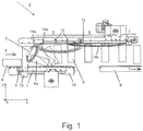
- FIGS. 1 and 2 show an embodiment of the invention in a simplified representation.
- a Zargenaufstellvorraum comes in the production of metal cans used, in which an establishment of horizontally funded can bodies 4 is necessary.
- the welded can bodies normally leave the corresponding system components lying down and are set up for further processing.
- the erection direction is defined as follows: Set up the rear section: the box rotates over the leading edge.
- FIGS. 1 and 2 show a preferred embodiment of a Zargenaufstellvortechnisch Z.
- Lying can bodies 4 arrive in the embodiment shown by Fig. 1 from the left into the erection device Z and leave it to the right in the direction of the arrow T.
- the Zargenaufstellvortechnisch Z includes an inlet conveyor 10, on which the lying frames 4 get into a storage room of the erector Z, a transport device 12, the already erected frames 9 magnetically transported hanging and a transport device 8 which placed the cans standing transported to further processing modules.
- the further transport device 8 may be part of the Zargenaufstellvortechnische Z, as in the presently described embodiment, or it may be part of a subsequent module that takes over the frames of the transport device 12.
- the infeed conveyor 10 and the forwarding device 8 are e.g. the transport belts known to the person skilled in the art, as are known to be used in can making plants.
- the transport device 12 may also be designed as a conveyor belt and also known to those skilled drive means, pulleys and support rollers.
- a magnet assembly 6 is further arranged (called fourth magnet assembly) which is preferably designed as a single-track permanent magnet or permanent magnet track 6, but can also be shaped differently; For example, the permanent magnet web can also be double-tracked.
- an electromagnet can also be used here.
- the magnetic field generated by the permanent magnet 6 exerts an attractive force on the raised frames, which is high enough around the frames 9 am Keep conveyor belt of the conveyor 12 hanging.
- the single-track permanent magnet 6 extends beyond the further transport device 8 to a Zargenabschitzstelle 7, at which the magnetically suspended erected frames 9 are delivered to the further transport device 8. The delivery can take place in that the erected frames simply fall on the conveyor belt of the forwarding device 8 or they can be controlled by means of measures not described here but known to those skilled in these.
- FIG. 1 is the setting up of the horizontal Be fiscalerzargen 4 by means of the erector Z by tilting over the leading edge or the leading edge of the can body 4 shown.
- Drive means such as motors, pulleys and support rollers, are only partially shown, but are known in the art.
- the setup process involves several of the magnet arrangements, which will be described in detail below.
- the frame 4 enters the installation space horizontally and is thereby held on the conveyor belt of the intake transport device 10 by means of a first magnet arrangement 1.
- the first magnet arrangement 1 is formed by at least one electromagnet, which in the activated state holds the lying frame 4 on the intake transport device 10 and, in the deactivated state, releases the lying frame 4.
- a second magnet arrangement 2 is formed by at least one permanent magnet, in this example formed by a plate which is arranged inclined transversely to the transport direction in the transport direction.
- the second magnet arrangement 2 is arranged in such a way that it forms an angle ⁇ to the vertical y which is essentially constant over its extension in the z-direction transverse to the transport direction T, x, where 0 ⁇ ⁇ ⁇ 90 °.
- the second magnet arrangement 2 is transverse to Transport direction T (z-direction) aligned and inclined relative to the yz plane in the transport direction T, x by the angle ⁇ .
- a distance of a lower extremity of the second magnet arrangement 2 from the inlet transport device 10 and / or the angle ⁇ are adjustable.
- the Zargenaufstellvortechnische Z can be adapted to different sizes frames. For example, if lying frames with a larger diameter in the device, the second magnet assembly 2 can be raised or lowered in frames with a smaller diameter. The change of the inclination (angle ⁇ ) is helpful for an adjustment of the trajectory of the frame 4a during erection.
- a third magnet arrangement 3 is designed as a double-track permanent magnet rail. It is arranged above the intake transport device 10 and the transport device 12. Preferably, a distance between the tracks of the permanent magnet rail 3 substantially corresponds to a Zargen bemesser. It may be a track width adjustment device 11 (see. Fig. 2 ), by means of which the distance is adjustable. This increases the flexibility of the Zargenaufstellvorplatz Z with respect to the safe, and preferably central receiving the erected frames 9 at different Zargen trimmesser.
- the first magnetic means 1 which is described here as an electromagnet, as a permanent magnet, in which case its Activation or deactivation, again by means of the controller 13 and any drive means, by a more or less pronounced magnetic shielding of the magnet in the direction of the frames 4, 4a, 9 takes place.
- the first magnetic means 1 which is described here as an electromagnet
- the controller 13 controls the controller 13 and any drive means, by a more or less pronounced magnetic shielding of the magnet in the direction of the frames 4, 4a, 9 takes place.
- elements of Supra 50 or Supra 60 or ⁇ -metal come into question.
- the erection device Z comprises a sensor 5 for detecting the incoming, lying frame 4, wherein the sensor 5 transmits position data of the lying frame 4 to the controller 13.
- the sensor can be configured, for example, as a light barrier sensor, wherein other common and suitable sensor types can also be used.
- the sensor 5 detects the arrival of a lying frame, in particular an arrival of the front edge of the frame 4, and transmits a corresponding signal to the controller 13.
- the controller 13 activates the electromagnet 1, so that the lying frame 4 is held on the inlet conveyor 10, while it is transported on and arrives under the permanent magnet 2.
- the electromagnet 1 is deactivated, so that the trailing edge of the lying frame 4 is detected by the magnetic field of the permanent magnet 2 and consequently lifted.
- Fig. 1 shows a snapshot of the deployment process after the solenoid 1 has been deactivated and frame 4a is exposed only to the magnetic field of the permanent magnet 2. Field lines of this magnetic field are shown schematically by the reference numeral 14a.
- the deactivation of the electromagnet 1 is delayed with respect to an activation time, depending on a transport speed and a height of the frame 4.
- the time of deactivation is calculated by the controller 13 on the basis of the previously determined entry time of the frame 4 in the installation room.
- this can also be used for detecting the trailing edge of the frame 4, if it can be arranged directly under the permanent magnet 2. In this way, the detection of the edges for activating or deactivating the electromagnet 1 can serve directly.
- Another solution in this sense can include two sensors, with a sensor for the detection of the leading edge and a sensor for the detection of the trailing edge.
- the trailing edge of the frame 4a Due to the increase in the trailing edge of the frame 4a, the trailing edge comes in the sphere of influence of the double-track permanent magnet rail 3 and is further raised until the frame 4a lifts off from the intake conveyor 10.
- the frame 4a on the one hand describes a translational movement in the transport direction T due to inertia and on the other hand a vertical movement, now primarily due to the action of the magnetic field of the double-track magnetic rail 3 (the influence of the permanent magnet magnet 2 disappears more and more with increasing distance of the frame 4a of this) , The superimposition of these movements yields the in Fig. 1 illustrated trajectory of the frame 4a (shown in phantom).
- Field lines of the magnetic field of the double-track magnetic track 3 are indicated schematically by the reference numeral 14b.
- the trailing edge is exposed to the magnetic field 14a and 14b and comes increasingly into the influence of the magnetic field 14b, which is illustrated by the other two dashed representations of the frame 4a.
- the frame 4a is erected and is magnetic by the transport device 12 suspended transported.
- Magnetic field lines of the competent single-track permanent magnet 6 are shown schematically with the field lines 14c.
- the magnetically suspended frame 9 is then delivered to the further transport device 8 in the manner described above.
Landscapes
- Engineering & Computer Science (AREA)
- Mechanical Engineering (AREA)
- Non-Mechanical Conveyors (AREA)
- Load-Engaging Elements For Cranes (AREA)
- Attitude Control For Articles On Conveyors (AREA)
- Control Of Conveyors (AREA)
Description
- Die Erfindung betrifft eine magnetische Zargenaufstellvorrichtung nach dem Oberbegriff des Anspruchs 1, eine Vorrichtung zur Herstellung von Dosen mit einer solchen Zargenaufstellvorrichtung und eine Verwendung einer solchen Zargenaufstellvorrichtung.
- Bei der Herstellung von Dosenzargen, nachdem die Zarge die Schweissmaschine verlassen hat, wird sie direkt weiterverarbeitet oder es wird die aufgebrachte Nahtabdeckung eingebrannt. Für nachfolgende Operationen wird die liegende Dose in der Regel in die aufrechte, vertikale Lage gebracht. Es sind Zargenaufsteller bekannt, bei denen dies mit Hilfe eines Magnetfelds erfolgt. Dabei geschieht das Aufstellen üblicherweise über die Vorderkante der Zarge, so dass sich das Hinterteil der Zarge nach oben bewegt. Bekannte magnetische Zargenaufsteller arbeiten mit Magnetkästen die beidseits des Förderwegs der Zarge angeordnet sind.
- Ein Beispiel für eine solche Aufstellvorrichtung ist ein magnetischer Zargenaufsteller der Firma O.S. Walker Magnetics, USA. Mit diesem Zargenaufsteller wird die Zarge über deren vorlaufende Kante bzw. die Vorderkante gedreht bzw. gekippt, so dass die Zarge mit ihrem Hinterteil aufgestellt wird. Durch die Aneinanderreihung von Magnetkörpern, welche aus einzelnen Magneten bestehen die in einem verschlossenen Kasten angeordnet sind, entsteht ein Magnetfeld, welches einem einzelnen grossen Magneten entspricht. Mit Hilfe zweier Magnetkästen beidseits des Förderwegs der Zargen wird die Zarge zentriert, was die Gefahr von Kratzern auf dem Zargenlack reduziert. Diese Lösung funktioniert für verschiedenste Zargendurchmesser und -höhen und ist somit eine Universallösung, welche die Zargen mit ihrem Hinterteil aufstellt.
- Ein weiterer magnetischer Zargenaufsteller ist von der Firma NSM Magnettechnik GmbH, Deutschland, bekannt und ist für dedizierte Fertigungslinien ausgebildet, bei welchen die Zargenhöhe und der Zargendurchmesser im Wesentlichen festgelegt sind. Dieser Zargenaufsteller arbeitet mit weniger Magneten, die zu einzelnen speziell angeordneten Magnetstäben zusammengefasst sind, die in verschlossenen Magnetkästen beidseits des Transportweges der Zargen in genau spezifizierter Lage angeordnet sind. Die Anordnung der Magnetstäbe ist dabei so getroffen, dass dieser Zargenaufsteller entweder für das Aufstellen über die vorlaufende Kante der Zarge oder für das Aufstellen über die nachlaufende Kante der Zarge gebaut ist.
- Eine weitere Zargenaufstellvorrichtung ist in der Patentanmeldung
CH 706 991 A1 - Die Verwendung von Magnetkästen seitlich des Transportweges bringt eine Reihe von mehr oder minder ausgeprägten Nachteilen. Ein Nachteil liegt darin, dass eine erhöhte Gefahr der Kontaktierung der Magnetkästen mit den transportierten Zargen besteht, was zu einer Beschädigung der Zargen führen kann. Ferner können solche Magnetkästen schwer zu montieren und zu justieren sein. In Zusammenhang damit bringen sie den Nachteil dass der Einblick in das Innere der Vorrichtung durch ihre Lage versperrt wird, so dass der Zugang zur Vorrichtung erschwert ist. Ferner kann die Flugbahn bzw. der Aufstellvorgang der Zargen nicht oder schwerlich beobachtet werden, so dass sich Nachjustierungen der Vorrichtung schwierig gestalten.
- Die internationale Patentanmeldung
WO 2014/043821 A1 offenbart eine magnetische Zargenaufstellvorrichtung nach Anspruch 1. Diese umfasst ein erstes Transportmittel für liegende Dosenzargen und ein zweites Transportmittel für aufgestellte Dosenzargen. Dabei können die Dosenzargen wahlweise mit ihrem Hinterteil oder mit ihrem Vorderteil aufgestellt werden. - Es stellt sich daher die Aufgabe, eine magnetische Aufstellvorrichtung für Dosenzargen zu schaffen, welche Abhilfe im Hinblick auf die genannten Nachteile bringt.
- Diese Aufgabe wird mit einer erfindungsgemässen Zargenaufstellvorrichtung gelöst. Die magnetische Zargenaufstellvorrichtung umfasst eine Einlauftransporteinrichtung zur Förderung von liegenden Zargen, eine über der Einlauftransporteinrichtung angeordnete Transporteinrichtung zur Förderung aufgestellter, an der Transporteinrichtung hängender Zargen, und eine Steuerung. Eine erste durch die Steuerung steuerbar aktivierbare und deaktivierbare Magnetanordnung ist unter der Einlauftransporteinrichtung derart angeordnet, dass eine auf der Einlauftransporteinrichtung liegende Zarge auf der Einlauftransporteinrichtung freigebbar magnetisch festhaltbar ist. Eine zweite Magnetanordnung ist über einem Bereich der Einlauftransporteinrichtung, in welchem die Zargen transportiert werden, angeordnet und derart ausgestaltet, dass eine auf der Einlauftransporteinrichtung liegende Zarge mittels des Magnetfelds der zweiten Magnetanordnung bei deaktiviertem Magnetfeld der ersten Magnetanordnung anhebbar ist. Eine dritte Magnetanordnung ist über der Transporteinrichtung vorgesehen und derart ausgestaltet und angeordnet, dass eine angehobene Zarge weiter anhebbar und von der Einlauftransporteinrichtung abhebbar ist und an der Transporteinrichtung magnetisch hängend aufgestellt transportierbar ist. Die Steuerung ist ausgestaltet, um die erste Magnetanordnung zu aktivieren, wenn eine Vorderkante einer auf der Einlauftransporteinrichtung liegenden Zarge die zweite Magnetanordnung passiert und um die erste Magnetanordnung zu deaktivieren, wenn eine nachlaufende Kante dieser Zarge unter der zweiten Magnetanordnung zu liegen kommt.
- Ferner wird die Aufgabe mit einer Vorrichtung zur Herstellung von Dosenzargen mit mindestens einer Zargenaufstellvorrichtung nach einem der vorangehenden Ansprüche gelöst.
- Die erfindungsgemässe Zargenaufstellvorrichtung hat einerseits den Vorteil, dass keine Magnetkästen seitlich der Einlauftransporteinrichtung benötigt werden, die einerseits im Hinblick auf ihre Konstruktion komplexer und daher teurer sind und andererseits den Einblick in den Aufstellraum aufgrund ihrer Lage verdecken. Folglich ist die erfindungsgemässe Zargenaufstellvorrichtung günstiger in der Herstellung und sie lässt sich in Bezug auf "Flugbahn" der Zargen zwischen ihrer liegenden und ihrer aufgestellten Position besser beobachten bzw. justieren, bzw. nachjustieren. Ein weiterer Vorteil liegt darin, dass die Beschädigungsgefahr der Zargen durch eventuelle Kontaktierung mit seitlichen Magnetkästen ausgeräumt wird.
- Die erfindungsgemässe Zargenaufstellvorrichtung kann zur Aufstellung von Zargen mit gängigen Abmessungen, aber insbesondere auch für Zargen mit einem Längen zu Durchmesserverhältnis von 3 zu 1 verwendet werden.
- Weitere Ausgestaltungen, Vorteile und Anwendungen der Erfindung ergeben sich aus den abhängigen Ansprüchen und aus der nun folgenden Beschreibung anhand der Figuren. Dabei zeigen:
-
Fig. 1 eine schematische Seitenansicht einer erfindungsgemässen Zargenaufstellvorrichtung, und -
Fig. 2 die Zargenaufstellvorrichtung ausFig. 2 in einer Ansicht in Transportrichtung. - Bemerkungen und Definitionen:
Verschiedene Bezugszeichen der Zargen sollen die verschiedenen Zustände der Zargen in Bezug auf Ihre Ausrichtung gegenüber einer Einlauftransporteinrichtung 10 (Fig. 1 ) verdeutlichen. Demgemäss werden liegende Zargen mit dem Bezugszeichen 4, Zargen die aufgestellt sind und magnetisch hängend transportiert werden mit dem Bezugszeichen 9 und Zargen die sich in einer Transitionsphase zwischen dem liegenden und dem aufgestellten Zustand befinden mit dem Bezugszeichen 4a bezeichnet. - Der Begriff "freigebbar" im Zusammenhang mit einem Magneten bedeutet hier dass die magnetische Feldstärke des Magneten nur so stark ist, dass die sich im Wirkungsfeld dieses Magneten befindende Zarge durch einen vordefinierten äusseren Krafteinfluss an- bzw. abhebbar ist, oder dass sie nicht vorhanden ist. Entsprechend bedeutet "festhaltbar" dass die magnetische Feldstärke des Magneten so stark ist, dass die sich im Wirkungsfeld dieses Magneten befindende Zarge durch den vordefinierten äusseren Krafteinfluss nicht an- bzw. abhebbar ist. In diesem Zusammenhang wird unter dem Begriff "deaktivierbar" in Bezug auf Magneten nicht nur eine vollkommene Abschaltung bzw. Entfernung des Magneten verstanden, sondern es kann sich dabei auch nur lediglich um eine mindestens teilweise Abschirmung (bei Permanentmagneten) oder eine Reduzierung des Stroms (bei Elektromagneten) handeln. Entsprechend wird unter dem Begriff "aktivierbar" in Bezug auf Magneten nicht nur eine Einschaltung bzw. ein Einbringen des Magneten verstanden, sondern es kann sich dabei auch um eine mindestens teilweise Entfernung einer Abschirmung (bei Permanentmagneten) oder eine Erhöhung des Stroms (bei Elektromagneten) handeln.
- Der Begriff "Höhe" einer Zarge bezieht sich auf die vertikale Abmessung der Zarge im aufgestellten Zustand.
- Ein "Magnetkasten" ist ein Kasten der mindestens einen Magneten, insbesondere mehrere Magnete, in einer speziellen räumlichen Anordnung beherbergt.
- Eine "Magnetanordnung" kann im Zusammenhang dieses Dokuments nur einen oder auch mehrere Magnete umfassen.
- Ein "Aufstellraum" ist im vorliegenden Zusammenhang definiert als der Raum in dem die Zarge vom liegenden in den aufgestellt magnetisch hängenden Zustand übergeht.
- Zur Vereinfachung der räumlichen Beschreibung ist in den Figuren ein Koordinatensystem eingezeichnet, mit einer x-Achse die einer Transportrichtung T der Zargen entspricht, einer y-Achse die der Vertikalen entspricht, und einer z-Achse die senkrecht auf die x-Achse in die Zeichenebene hinein verläuft.
- Der Begriff "über der Einlauftransporteinrichtung" oder "über einen Bereich der Einlauftransporteinrichtung" ist im vorliegenden Zusammenhang so zu verstehen, dass sich ein Objekt auf das sich dieser Begriff bezieht keinen oder einen vernachlässigbaren Versatz in z-Richtung gegenüber der Einlauftransporteinrichtung hat.
- Die
Figuren 1 und2 zeigen ein Ausführungsbeispiel der Erfindung in vereinfachter Darstellung. Eine Zargenaufstellvorrichtung kommt bei der Herstellung von Metalldosen zum Einsatz, bei welcher ein Aufstellen von liegend geförderten Dosenzargen 4 nötig ist. So verlassen die geschweissten Dosenzargen nach der Abdeckung der geschweissten Naht mit einer Beschichtung die entsprechenden Anlageteile in der Regel liegend und werden für die Weiterbearbeitung aufgestellt. Für das Aufstellen wird die Aufstellrichtung wie folgt definiert: Hinterteil aufstellen: die Dose dreht sich über die vorlaufende Kante. - Die
Figuren 1 und2 zeigen eine bevorzugte Ausführungsform einer Zargenaufstellvorrichtung Z. Dabei bezieht sich die nachfolgende Beschreibung auf beide Figuren, da sie dieselbe Ausführungsform zeigen, aber der Klarheit halber zwei verschiedene Ansichten darstellen. Liegende Dosenzargen 4 gelangen in dem gezeigten Ausführungsbeispiel vonFig. 1 von links her in die Aufstellvorrichtung Z und verlassen diese nach rechts in Richtung des Pfeils T. Dabei umfasst die Zargenaufstellvorrichtung Z eine Einlauftransporteinrichtung 10, auf der die liegenden Zargen 4 in einen Aufstellraum der Aufstellvorrichtung Z gelangen, eine Transporteinrichtung 12 die schon aufgestellte Zargen 9 magnetisch hängend transportiert und eine Weitertransporteinrichtung 8 die die Dosen aufgestellt stehend an Weiterverarbeitungsmodulen transportiert. - Die Einlauftransporteinrichtung 10 umfasst eine doppelspurige Transportbahn für den Transport der liegenden Zargen 4. Damit ist eine präzise Zuführung der liegenden Zargen 4 in den Aufstellraum möglich.
- Die Weitertransporteinrichtung 8 kann Teil der Zargenaufstellvorrichtung Z sein, wie in der vorliegend beschriebenen Ausführungsform, oder sie kann Teil eines nachfolgenden Moduls sein, das die Zargen von der Transporteinrichtung 12 übernimmt.
- Die Einlauftransporteinrichtung 10 und die Weitertransporteinrichtung 8 sind z.B. dem Fachmann bekannte Transportbänder, wie sie bei den Anlagen zur Dosenherstellung bekanntermassen verwendet werden.
- Die Transporteinrichtung 12 kann ebenfalls als Transportband ausgeführt sein und ebenfalls dem Fachmann bekannten Antriebsmittel, Umlenkrollen und Stützrollen aufweisen. Über der Transporteinrichtung 12 ist ferner eine Magnetanordnung 6 angeordnet (genannt vierte Magnetanordnung) welche vorzugsweise als einspuriger Permanentmagnet bzw. Permanentmagnetbahn 6 ausgeführt ist, aber auch anders geformt sein kann; z.B. kann die Permanentmagnetbahn auch doppelspurig sein. Insbesondere kann hier auch ein Elektromagnet zum Einsatz kommen. Das vom Permanentmagneten 6 erzeugte Magnetfeld übt eine Anziehungskraft auf die aufgestellten Zargen, die hoch genug ist um die Zargen 9 am Transportband der Transporteinrichtung 12 hängend zu halten. Der einspurige Permanentmagnet 6 erstreckt sich bis über der Weitertransporteinrichtung 8 bis zu einer Zargenabwurfstelle 7, an der die magnetisch hängenden aufgestellten Zargen 9 an die Weitertransporteinrichtung 8 abgegeben werden. Die Abgabe kann dadurch erfolgen, dass die aufgestellten Zargen einfach auf das Transportband der Weitertransporteinrichtung 8 fallen oder sie können kontrolliert mittels hier nicht beschriebenen aber dem Fachmann bekannten Massnahmen auf diese abgestellt werden.
- In
Figur 1 ist das Aufstellen der liegenden Behälterzargen 4 mittels der Aufstellvorrichtung Z durch ein Kippen über die vorlaufende Kante bzw. den vorlaufenden Rand der Dosenzarge 4 gezeigt. Antriebsmittel, wie Motoren, Umlenkrollen und Stützrollen, sind nur teilweise dargestellt, sind dem Fachmann aber bekannt. - Am Aufstellprozess sind mehrere der Magnetanordnungen beteiligt, die im Folgenden im Detail beschrieben werden.
- Wie erwähnt tritt die Zarge 4 liegend in den Aufstellraum ein und wird dabei auf dem Transportband der Einlauftransporteinrichtung 10 mittels einer ersten Magnetanordnung 1 festgehalten. Die erste Magnetanordnung 1 ist von mindestens einem Elektromagneten gebildet, welcher in aktiviertem Zustand die liegende Zarge 4 auf der Einlauftransporteinrichtung 10 festhält und in deaktiviertem Zustand die liegende Zarge 4 freigibt.
- Eine zweite Magnetanordnung 2 ist durch mindestens einen Permanentmagneten gebildet, in diesem Beispiel gebildet durch eine Platte, die quer zur Transportrichtung in Transportrichtung geneigt angeordnet ist. Allgemein ist die zweite Magnetanordnung 2 derart angeordnet, dass sie einen über ihre Ausdehnung in der z-Richtung quer zur Transportrichtung T, x im Wesentlichen konstanten Winkel α zur Vertikalen y bildet, wobei 0 ≤ α < 90° ist. Mit anderen Worten ist die zweite Magnetanordnung 2 quer zur Transportrichtung T (z-Richtung) ausgerichtet und gegenüber der yz-Ebene in Transportrichtung T, x um den Winkel α geneigt. Vorzugsweise sind ein Abstand einer unteren Extremität der zweiten Magnetanordnung 2 von der Einlauftransporteinrichtung 10 und/oder der Winkel α einstellbar. Damit kann die Zargenaufstellvorrichtung Z an verschieden grosse Zargen angepasst werden. Kommen beispielsweise liegende Zargen mit einem grösseren Durchmesser in die Vorrichtung, so kann die zweite Magnetanordnung 2 angehoben bzw. bei Zargen mit kleinerem Durchmesser abgesenkt werden. Die Änderung der Neigung (Winkel α) ist hilfreich für eine Justierung der Flugbahn der Zarge 4a während des Aufstellens.
- Eine dritte Magnetanordnung 3 ist als doppelspurige Permanentmagnetschiene ausgebildet. Sie ist über der Einlauftransporteinrichtung 10 und der Transporteinrichtung 12 angeordnet. Vorzugsweise entspricht ein Abstand zwischen den Spuren der Permanentmagnetschiene 3 im Wesentlichen einem Zargendurchmesser. Es kann eine Spurbreitenverstellungseinrichtung 11 (vgl.
Fig. 2 ) vorgesehen sein, mittels welcher der Abstand einstellbar ist. Dies erhöht die Flexibilität der Zargenaufstellvorrichtung Z in Bezug auf die sichere, und vorzugsweise mittige Aufnahme der aufgestellten Zargen 9 bei verschiedenen Zargendurchmesser. - Es wird darauf hingewiesen dass alle im Rahmen der beschriebenen Ausführungsform der Zargenaufstellvorrichtung Z als Permanentmagnete ausgewiesene Magnete auch als Elektromagnete ausführbar sind. In diesem Fall übernimmt eine Steuerung 13, die nachfolgend näher beschrieben wird, die Aufgabe der Koordinierung der Aktivierung bzw. Deaktivierung der einzelnen Magneten.
- Es ist aber auch möglich, obgleich wegen der höheren Komplexität nicht bevorzugt, das erste Magnetmittel 1, das hier als Elektromagnet beschrieben wird, als Permanentmagnet auszuführen, wobei in diesem Fall seine Aktivierung bzw. Deaktivierung, wieder mittels der Steuerung 13 und etwaiger Antriebsmittel, durch eine mehr oder weniger ausgeprägte magnetische Abschirmung des Magneten in Richtung der Zargen 4, 4a, 9 erfolgt. Dabei kommen Elemente aus Supra 50 oder Supra 60 oder µ-Metall in Frage.
- Im Folgenden wird die Funktionsweise der Aufstellvorrichtung Z, insbesondere im Hinblick auf die im Aufstellraum stattfindenden Vorgänge, erläutert.
- Die Aufstellvorrichtung Z umfasst einen Sensor 5 zur Erkennung der einlaufenden, liegenden Zarge 4, wobei der Sensor 5 Positionsdaten der liegenden Zarge 4 an die Steuerung 13 übermittelt. Der Sensor kann beispielsweise als Lichtschrankensensor ausgebildet sein, wobei andere gängige und in Frage kommende Sensortypen auch zum Einsatz kommen können.
- Der Sensor 5 detektiert das Ankommen einer liegenden Zarge, insbesondere ein Ankommen der Vorderkante der Zarge 4, und übermittelt ein entsprechendes Signal an die Steuerung 13. Die Steuerung 13 aktiviert den Elektromagneten 1, so dass die liegende Zarge 4 an der Einlauftransportvorrichtung 10 festgehalten wird, während sie weitertransportiert wird und unter dem Permanentmagneten 2 ankommt. Sobald die nachlaufende Kante der liegenden Zarge 4 den Permanentmagneten 2 passiert hat wird der Elektromagnet 1 deaktiviert, so dass die nachlaufende Kante der liegenden Zarge 4 vom Magnetfeld des Permanentmagneten 2 erfasst und infolgedessen angehoben wird.
Fig. 1 zeigt eine Momentaufnahme des Aufstellvorgangs nachdem der Elektromagnet 1 deaktiviert wurde und Zarge 4a nur noch dem Magnetfeld des Permanentmagneten 2 ausgesetzt ist. Feldlinien dieses Magnetfelds sind schematisch mit dem Bezugszeichen 14a dargestellt. - Die Deaktivierung des Elektromagneten 1 erfolgt zeitverzögert bezogen auf einen Aktivierungszeitpunkt, in Abhängigkeit von einer Transportgeschwindigkeit und einer Höhe der Zarge 4. Der Zeitpunkt der Deaktivierung wird von der Steuerung 13 auf der Basis des zuvor festgestellten Eintrittszeitpunkts der Zarge 4 in den Aufstellraum errechnet. Je nach baulich bedingte Anordnung des Sensors 5 kann dieser auch zur Detektion der nachlaufenden Kante der Zarge 4 verwendet werden, wenn er unmittelbar unter dem Permanentmagneten 2 angeordnet werden kann. Auf diese Weise kann direkt die Detektion der Kanten zur Aktivierung bzw. Deaktivierung des Elektromagneten 1 dienen. Dies hat den Vorteil dass die Höhe der Zarge und die Transportgeschwindigkeit nicht bekannt sein müssen. Eine weitere Lösung in diesem Sinne kann zwei Sensoren umfassen, wobei ein Sensor für die Detektion der vorlaufenden Kante und ein Sensor für die Detektion der nachlaufenden Kante dienen.
- Aufgrund der Anhebung der nachlaufenden Kante der Zarge 4a kommt die nachlaufende Kante im Einflussbereich der doppelspurigen Permanentmagnetschiene 3 und wird weiter angehoben, bis die Zarge 4a von der Einlauftransporteinrichtung 10 abhebt. Dabei beschreibt die Zarge 4a einerseits eine translatorische Bewegung in Transportrichtung T aufgrund der Trägheit und andererseits eine vertikale Bewegung, jetzt primär aufgrund der Einwirkung des Magnetfelds der doppelspurigen Magnetschiene 3 (der Einfluss des Permanentmagnetmagneten 2 schwindet immer mehr mit zunehmender Entfernung der Zarge 4a von diesem). Die Überlagerung dieser Bewegungen ergibt die in
Fig. 1 dargestellte Flugbahn der Zarge 4a (gestrichelt dargestellt). Feldlinien des Magnetfelds der doppelspurigen Magnetschiene 3 sind schematisch mit dem Bezugszeichen 14b bezeichnet. Wie in der Figur ersichtlich ist bei der am meisten geneigten gestrichelten Darstellung der Zarge 4a die hintere Kante dem Magnetfeld 14a und 14b ausgesetzt und kommt zunehmend in den Einflussbereich des Magnetfelds 14b, was mit den anderen beiden gestrichelten Darstellungen der Zarge 4a verdeutlicht ist. Schliesslich ist die Zarge 4a aufgestellt und wird von der Transporteinrichtung 12 magnetisch hängend weitertransportiert. Magnetische Feldlinien des dafür zuständigen einspurigen Permanentmagneten 6 sind schematisch mit den Feldlinien 14c dargestellt. - Die magnetisch hängende Zarge 9 wird dann auf die oben beschriebene Weise an die Weitertransporteinrichtung 8 abgegeben.
- Obwohl bevorzugte Ausführungsformen der Erfindung beschrieben worden sind wird darauf hingewiesen, dass die Erfindung auf anderen Weisen im Rahmen der nachfolgenden Ansprüchen realisiert werden kann. Dabei beziehen sich in der Beschreibung verwendete Begriffe wie "bevorzugt", "insbesondere", "vorteilhaft", etc. nur auf optionale und beispielhafte Ausführungsformen.
Claims (12)
- Magnetische Zargenaufstellvorrichtung (Z), welche eine Einlauftransporteinrichtung (10) zur Förderung von liegenden Zargen (4), eine über der Einlauftransporteinrichtung (10) angeordnete Transporteinrichtung (12) zur Förderung aufgestellter, an der Transporteinrichtung (12) hängender Zargen (9) und eine Steuerung (13) umfasst, wobei eine erste durch die Steuerung (13) steuerbar aktivierbare und deaktivierbare Magnetanordnung (1) unter der Einlauftransporteinrichtung (10) derart angeordnet ist, dass eine auf der Einlauftransporteinrichtung (10) liegende Zarge (4) auf der Einlauftransporteinrichtung (10) freigebbar magnetisch festhaltbar ist, wobei eine zweite Magnetanordnung (2) über einem Bereich der Einlauftransporteinrichtung (10), in welchem die Zargen transportiert werden, angeordnet und derart ausgestaltet ist, dass eine auf der Einlauftransporteinrichtung (10) liegende Zarge (4) mittels des Magnetfelds der zweiten Magnetanordnung (2) bei deaktiviertem Magnetfeld der ersten Magnetanordnung (1) anhebbar ist, wobei eine dritte Magnetanordnung (3) über der Transporteinrichtung (12) vorgesehen und derart ausgestaltet und angeordnet ist, dass eine angehobene Zarge (4a) weiter anhebbar und von der Einlauftransporteinrichtung (10) abhebbar ist und an der Transporteinrichtung (12) magnetisch hängend aufgestellt transportierbar ist, dadurch gekennzeichnet, dass die Steuerung (13) ausgestaltet ist, um die erste Magnetanordnung (1) zu aktivieren, wenn eine Vorderkante einer auf der Einlauftransporteinrichtung (10) liegenden Zarge (4) die zweite Magnetanordnung (2) passiert und um die erste Magnetanordnung (1) zu deaktivieren, wenn eine nachlaufende Kante dieser Zarge (4) unter der zweiten Magnetanordnung (2) zu liegen kommt.
- Magnetische Zargenaufstellvorrichtung nach Anspruch 1, wobei die erste Magnetanordnung (1) von mindestens einem Elektromagneten gebildet ist, welcher in aktiviertem Zustand die liegende Zarge (4) auf der Einlauftransporteinrichtung (10) festhält und in deaktiviertem Zustand die liegende Zarge (4) freigibt.
- Magnetische Zargenaufstellvorrichtung nach Anspruch 1 oder 2, wobei die zweite Magnetanordnung (2) durch mindestens einen Permanentmagneten gebildet ist.
- Magnetische Zargenaufstellvorrichtung nach einem der vorangehenden Ansprüche, wobei die zweite Magnetanordnung (2) quer zur Transportrichtung (T) ausgerichtet und um einen Winkel (α), bezüglich einer vertikalen Querebene (yz), in Transportrichtung (T, x) geneigt ist, wobei 0 ≤ α < 90°, insbesondere wobei ein Abstand einer unteren Extremität der zweiten Magnetanordnung (2) von der Einlauftransporteinrichtung und/oder der Winkel (α) einstellbar sind bzw. ist.
- Magnetische Zargenaufstellvorrichtung nach einem der vorangehenden Ansprüche, wobei die dritte Magnetanordnung (3) als doppelspurige Permanentmagnetschiene ausgebildet ist.
- Magnetische Zargenaufstellvorrichtung nach Anspruch 5, wobei ein Abstand zwischen den Spuren der Permanentmagnetschiene (3) im Wesentlichen einem Zargendurchmesser entspricht, insbesondere wobei der Abstand mittels einer Spurbreitenverstellungseinrichtung (11) einstellbar ist.
- Magnetische Zargenaufstellvorrichtung nach einem der vorangehenden Ansprüche, wobei mindestens ein Sensor (5) zur Erkennung der einlaufenden, liegenden Zarge (4) vorgesehen ist, wobei der Sensor (5) Positionsdaten der liegenden Zarge (4) an die Steuerung übermittelt.
- Magnetische Zargenaufstellvorrichtung nach Anspruch 7, wobei die Deaktivierung der ersten Magnetanordnung (1) zeitverzögert bezogen auf einen Aktivierungszeitpunkt in Abhängigkeit von einer Transportgeschwindigkeit und einer Höhe der Zarge erfolgt.
- Magnetische Zargenaufstellvorrichtung nach einem der vorangehenden Ansprüche, wobei im Anschluss an der dritten Magnetanordnung (3) eine vierte Magnetanordnung (6), insbesondere als einspuriger Permanentmagnet ausgebildet, die zum magnetisch hängenden Transport der aufgestellten Zargen (9) vorgesehen ist, wobei sich die vierte Magnetanordnung (6) bis über eine Weitertransporteinrichtung (8) bis zu einer Zargenabwurfstelle (7) erstreckt, an der die magnetisch hängenden aufgestellten Zargen (9) an die Weitertransporteinrichtung (8) abgebbar sind.
- Magnetische Zargenaufstellvorrichtung nach einem der vorangehenden Ansprüche, wobei die Einlauftransporteinrichtung (10) eine doppelspurige Transportbahn für den Transport der liegenden Zargen (4) umfasst.
- Vorrichtung zur Herstellung von Dosenzargen mit mindestens einer magnetischen Zargenaufstellvorrichtung (Z) nach einem der vorangehenden Ansprüche.
- Verwendung der magnetischen Zargenaufstellvorrichtung (Z) nach einem der Ansprüche 1 bis 10 zur Aufstellung von Zargen (4) mit einem Längen zu Durchmesserverhältnis von 3 zu 1.
Applications Claiming Priority (2)
| Application Number | Priority Date | Filing Date | Title |
|---|---|---|---|
| CH00666/14A CH709593A1 (de) | 2014-05-05 | 2014-05-05 | Magnetische Aufstellvorrichtung für Dosenzargen. |
| PCT/CH2015/000029 WO2015168811A1 (de) | 2014-05-05 | 2015-02-26 | Magnetische aufstellvorrichtung für dosenzargen |
Publications (2)
| Publication Number | Publication Date |
|---|---|
| EP3140228A1 EP3140228A1 (de) | 2017-03-15 |
| EP3140228B1 true EP3140228B1 (de) | 2019-01-02 |
Family
ID=52705906
Family Applications (1)
| Application Number | Title | Priority Date | Filing Date |
|---|---|---|---|
| EP15711416.6A Active EP3140228B1 (de) | 2014-05-05 | 2015-02-26 | Magnetische aufstellvorrichtung für dosenzargen |
Country Status (8)
| Country | Link |
|---|---|
| US (1) | US9845197B2 (de) |
| EP (1) | EP3140228B1 (de) |
| CN (1) | CN106458457B (de) |
| CH (1) | CH709593A1 (de) |
| ES (1) | ES2713449T3 (de) |
| PT (1) | PT3140228T (de) |
| TW (1) | TWI618664B (de) |
| WO (1) | WO2015168811A1 (de) |
Families Citing this family (12)
| Publication number | Priority date | Publication date | Assignee | Title |
|---|---|---|---|---|
| CN106477250B (zh) * | 2016-11-03 | 2018-06-01 | 北京领邦智能装备股份公司 | 振动上料装置和振动上料装置中的姿态校正方法 |
| US10241587B2 (en) * | 2016-12-22 | 2019-03-26 | Microsoft Technology Licensing, Llc | Magnetic tracker power duty cycling |
| CN106846825B (zh) * | 2017-04-06 | 2023-06-06 | 四川辉通云联数据科技有限公司 | 地磁车辆检测器、地磁车辆检测系统及方法 |
| WO2019078997A1 (en) * | 2017-10-17 | 2019-04-25 | Laitram, L.L.C. | DEVICE FOR MOVING LIM BOXES |
| CN108069071B (zh) * | 2017-12-22 | 2020-04-07 | 湖南津味绿康食品有限公司 | 一种罐头成品收集装置 |
| CN108741714B (zh) * | 2018-05-29 | 2019-10-22 | 深圳市芝麻大点科技有限公司 | 一种电子衣柜 |
| CN109482769B (zh) * | 2018-12-06 | 2023-12-22 | 江苏奥瑞金包装有限公司 | 一种罐体生产线 |
| CN110937392B (zh) * | 2019-12-09 | 2024-11-29 | 杭州国辰机器人科技有限公司 | 一种用于熨斗底板在抛光与喷砂间上下料的机器人工作站 |
| CN111882952B (zh) * | 2020-08-06 | 2021-12-21 | 许昌学院 | 一种英语翻译训练装置 |
| JP7401101B2 (ja) * | 2020-10-28 | 2023-12-19 | 株式会社ダイシン | 搬送物の整列方法及び搬送物整列システム |
| CN114604632B (zh) * | 2022-03-30 | 2024-05-03 | 珠海拾比佰新型材料有限公司 | 一种垛板装置及具有其的垛板机 |
| IT202200026370A1 (it) * | 2022-12-21 | 2024-06-21 | Officina Freddi S R L | Evacuatore magnetico per contenitori provvisti di tappo ferromagnetico |
Family Cites Families (14)
| Publication number | Priority date | Publication date | Assignee | Title |
|---|---|---|---|---|
| NL6902464A (en) | 1969-02-17 | 1970-08-19 | Erecting containers being transported on a - conveyor belt | |
| US3656234A (en) * | 1970-07-01 | 1972-04-18 | Malachy J Regan | Emollient applicator for use with electric shavers |
| US4235187A (en) * | 1978-10-30 | 1980-11-25 | Metalwash Machinery Corp. | Can handling equipment |
| GB2114083B (en) * | 1982-01-29 | 1985-11-06 | Metal Box Plc | Guiding articles between a single common path and a plurality of other paths |
| CH674974A5 (de) * | 1987-05-11 | 1990-08-15 | Praezisions Werkzeuge Ag | |
| DE4203290A1 (de) * | 1992-01-31 | 1993-08-05 | Blechbearbeitungsmaschinenwerk | Foerdereinrichtung fuer dosenzargen in oefen oder erwaermungsanlagen zum trocknen von pulver- und/oder lackschichten |
| EP0698569A1 (de) * | 1994-08-24 | 1996-02-28 | Nsm Magnettechnik Gmbh | Einrichtung zum Wenden von Gegenständen auf einer Transportstrecke, insbesondere zum Wenden von Dosendeckeln und Dosen u.dgl. |
| US5788049A (en) * | 1995-11-17 | 1998-08-04 | Fmc Corportion | Divergent contact cable can handling apparatus |
| JP2000506481A (ja) * | 1996-01-26 | 2000-05-30 | エルパトローニク アクチエンゲゼルシヤフト | 容器胴列を分ける又はまとめる方法及び装置 |
| US6227348B1 (en) * | 1996-01-26 | 2001-05-08 | Elpatronic Ag | Method and apparatus for separating and bringing together series of container bodies |
| AR020419A1 (es) * | 1998-09-14 | 2002-05-08 | Webb Int Co Jerwis B | Sistema transportador impulsado magneticamente y metodo para hacerlo. |
| US7506746B2 (en) * | 2002-08-31 | 2009-03-24 | Applied Materials, Inc. | System for transporting substrate carriers |
| DE102011016855B4 (de) * | 2011-04-13 | 2023-05-04 | Krones Aktiengesellschaft | Verfahren und Vorrichtung zum Transportieren von Behältnissen oder Behältnisgebinden |
| CH706991A1 (de) | 2012-09-18 | 2014-03-31 | Soudronic Ag | Magnetische Aufstellvorrichtung für Dosenzargen. |
-
2014
- 2014-05-05 CH CH00666/14A patent/CH709593A1/de not_active Application Discontinuation
-
2015
- 2015-02-26 WO PCT/CH2015/000029 patent/WO2015168811A1/de not_active Ceased
- 2015-02-26 CN CN201580023036.4A patent/CN106458457B/zh active Active
- 2015-02-26 EP EP15711416.6A patent/EP3140228B1/de active Active
- 2015-02-26 US US15/300,924 patent/US9845197B2/en active Active
- 2015-02-26 ES ES15711416T patent/ES2713449T3/es active Active
- 2015-02-26 PT PT15711416T patent/PT3140228T/pt unknown
- 2015-03-16 TW TW104108247A patent/TWI618664B/zh active
Non-Patent Citations (1)
| Title |
|---|
| None * |
Also Published As
| Publication number | Publication date |
|---|---|
| US9845197B2 (en) | 2017-12-19 |
| EP3140228A1 (de) | 2017-03-15 |
| CH709593A1 (de) | 2015-11-13 |
| ES2713449T3 (es) | 2019-05-21 |
| US20170022011A1 (en) | 2017-01-26 |
| CN106458457A (zh) | 2017-02-22 |
| TWI618664B (zh) | 2018-03-21 |
| WO2015168811A1 (de) | 2015-11-12 |
| PT3140228T (pt) | 2019-04-26 |
| CN106458457B (zh) | 2019-03-29 |
| TW201600433A (zh) | 2016-01-01 |
Similar Documents
| Publication | Publication Date | Title |
|---|---|---|
| CH709593A1 (de) | Magnetische Aufstellvorrichtung für Dosenzargen. | |
| EP3287396B1 (de) | Fördersystem mit segmenten | |
| DE19814141A1 (de) | Verfahren und Vorrichtung zum positionsgenauen Zuführen von flächenförmigen Gütern zu einem Bearbeitungsprozeß | |
| DE202011110089U1 (de) | Vorrichtung zum Ausrichten eines nicht-kreisrunden oder mehreckigen Gegenstands | |
| EP3087877B1 (de) | Kassensystemanordnung mit warentrennstaberkennung | |
| EP3354121B1 (de) | Verfahren zur werkstückerfassung sowie erfassungsvorrichtung | |
| DE102006015689A1 (de) | System und Verfahren zum Steuern einer Fördertechnik mittels rechnergestützter Bilderkennung | |
| WO2014043821A1 (de) | Magnetische aufstellvorrichtung für dosenzargen | |
| CH719300A1 (de) | Verfahren und Vorrichtung zum phasengenauen Übergeben von Stückgut. | |
| WO1997027132A1 (de) | Verfahren und vorrichtung zur auftrennung oder zusammenführung von behälterzargenabfolgen | |
| DE102014222382B4 (de) | Verfahren und Vorrichtung zur Zugbildung von Gegenständen in Transportanlagen | |
| EP2551202A1 (de) | Mehrspurige Schalenverschliessmaschine | |
| EP2060515B1 (de) | Vorrichtung und Verfahren zum gleichmäßigen Transport von Substraten | |
| DE102010035126A1 (de) | Verfahren und Vorrichtung zum kontrollierten Übergeben eines Stückguts von einem Zuführförderer auf einen Förderer | |
| EP2617667B1 (de) | Verfahren und Vorrichtung zum Bilden von Paketen bzw. Teilpaketen aus lose gestapelten Druckerzeugnissen | |
| DE102017109559B3 (de) | Vorrichtung zum Behandeln eines Metallbandes | |
| DE10261551B9 (de) | Drehvorrichtung | |
| EP3814256B1 (de) | Bodenlegeeinrichtung und verfahren zur herstellung von mit zumindest mit einem boden versehenen schlauchstücken | |
| DE10100191C2 (de) | Bogenanleger | |
| DE19743020C2 (de) | Vorrichtung sowie Verfahren zur Vereinzelung von Druckprodukten | |
| EP3132912A1 (de) | Vorrichtung zum ruhigstellen von kunststoffbehältern | |
| DE202015008475U1 (de) | Vorrichtung zum Drehen bzw. Orientieren von Stückgütern auf einer Stetigförderanlage | |
| EP1809557B1 (de) | Verfahren und vorrichtung zum einstecken von flachen gegenständen in druckprodukte | |
| EP3248919A1 (de) | Verfahren und vorrichtung zum abtrennen von einzelnen, flachen, biegbaren produkten von der unterseite eines stapels | |
| DE102023117666A1 (de) | Vorrichtung und Verfahren zum Bereitstellen von vorzugsweise flächenförmigen Klebeelementen |
Legal Events
| Date | Code | Title | Description |
|---|---|---|---|
| PUAI | Public reference made under article 153(3) epc to a published international application that has entered the european phase |
Free format text: ORIGINAL CODE: 0009012 |
|
| STAA | Information on the status of an ep patent application or granted ep patent |
Free format text: STATUS: REQUEST FOR EXAMINATION WAS MADE |
|
| 17P | Request for examination filed |
Effective date: 20160919 |
|
| AK | Designated contracting states |
Kind code of ref document: A1 Designated state(s): AL AT BE BG CH CY CZ DE DK EE ES FI FR GB GR HR HU IE IS IT LI LT LU LV MC MK MT NL NO PL PT RO RS SE SI SK SM TR |
|
| AX | Request for extension of the european patent |
Extension state: BA ME |
|
| DAX | Request for extension of the european patent (deleted) | ||
| GRAP | Despatch of communication of intention to grant a patent |
Free format text: ORIGINAL CODE: EPIDOSNIGR1 |
|
| STAA | Information on the status of an ep patent application or granted ep patent |
Free format text: STATUS: GRANT OF PATENT IS INTENDED |
|
| INTG | Intention to grant announced |
Effective date: 20181016 |
|
| GRAS | Grant fee paid |
Free format text: ORIGINAL CODE: EPIDOSNIGR3 |
|
| GRAA | (expected) grant |
Free format text: ORIGINAL CODE: 0009210 |
|
| STAA | Information on the status of an ep patent application or granted ep patent |
Free format text: STATUS: THE PATENT HAS BEEN GRANTED |
|
| AK | Designated contracting states |
Kind code of ref document: B1 Designated state(s): AL AT BE BG CH CY CZ DE DK EE ES FI FR GB GR HR HU IE IS IT LI LT LU LV MC MK MT NL NO PL PT RO RS SE SI SK SM TR |
|
| REG | Reference to a national code |
Ref country code: GB Ref legal event code: FG4D Free format text: NOT ENGLISH |
|
| REG | Reference to a national code |
Ref country code: CH Ref legal event code: EP Ref country code: AT Ref legal event code: REF Ref document number: 1084101 Country of ref document: AT Kind code of ref document: T Effective date: 20190115 |
|
| REG | Reference to a national code |
Ref country code: IE Ref legal event code: FG4D Free format text: LANGUAGE OF EP DOCUMENT: GERMAN |
|
| REG | Reference to a national code |
Ref country code: DE Ref legal event code: R096 Ref document number: 502015007512 Country of ref document: DE |
|
| REG | Reference to a national code |
Ref country code: NL Ref legal event code: FP |
|
| REG | Reference to a national code |
Ref country code: PT Ref legal event code: SC4A Ref document number: 3140228 Country of ref document: PT Date of ref document: 20190426 Kind code of ref document: T Free format text: AVAILABILITY OF NATIONAL TRANSLATION Effective date: 20190402 |
|
| REG | Reference to a national code |
Ref country code: ES Ref legal event code: FG2A Ref document number: 2713449 Country of ref document: ES Kind code of ref document: T3 Effective date: 20190521 |
|
| REG | Reference to a national code |
Ref country code: LT Ref legal event code: MG4D |
|
| PG25 | Lapsed in a contracting state [announced via postgrant information from national office to epo] |
Ref country code: NO Free format text: LAPSE BECAUSE OF FAILURE TO SUBMIT A TRANSLATION OF THE DESCRIPTION OR TO PAY THE FEE WITHIN THE PRESCRIBED TIME-LIMIT Effective date: 20190402 Ref country code: FI Free format text: LAPSE BECAUSE OF FAILURE TO SUBMIT A TRANSLATION OF THE DESCRIPTION OR TO PAY THE FEE WITHIN THE PRESCRIBED TIME-LIMIT Effective date: 20190102 Ref country code: SE Free format text: LAPSE BECAUSE OF FAILURE TO SUBMIT A TRANSLATION OF THE DESCRIPTION OR TO PAY THE FEE WITHIN THE PRESCRIBED TIME-LIMIT Effective date: 20190102 Ref country code: LT Free format text: LAPSE BECAUSE OF FAILURE TO SUBMIT A TRANSLATION OF THE DESCRIPTION OR TO PAY THE FEE WITHIN THE PRESCRIBED TIME-LIMIT Effective date: 20190102 Ref country code: PL Free format text: LAPSE BECAUSE OF FAILURE TO SUBMIT A TRANSLATION OF THE DESCRIPTION OR TO PAY THE FEE WITHIN THE PRESCRIBED TIME-LIMIT Effective date: 20190102 |
|
| PG25 | Lapsed in a contracting state [announced via postgrant information from national office to epo] |
Ref country code: LV Free format text: LAPSE BECAUSE OF FAILURE TO SUBMIT A TRANSLATION OF THE DESCRIPTION OR TO PAY THE FEE WITHIN THE PRESCRIBED TIME-LIMIT Effective date: 20190102 Ref country code: HR Free format text: LAPSE BECAUSE OF FAILURE TO SUBMIT A TRANSLATION OF THE DESCRIPTION OR TO PAY THE FEE WITHIN THE PRESCRIBED TIME-LIMIT Effective date: 20190102 Ref country code: IS Free format text: LAPSE BECAUSE OF FAILURE TO SUBMIT A TRANSLATION OF THE DESCRIPTION OR TO PAY THE FEE WITHIN THE PRESCRIBED TIME-LIMIT Effective date: 20190502 Ref country code: GR Free format text: LAPSE BECAUSE OF FAILURE TO SUBMIT A TRANSLATION OF THE DESCRIPTION OR TO PAY THE FEE WITHIN THE PRESCRIBED TIME-LIMIT Effective date: 20190403 Ref country code: RS Free format text: LAPSE BECAUSE OF FAILURE TO SUBMIT A TRANSLATION OF THE DESCRIPTION OR TO PAY THE FEE WITHIN THE PRESCRIBED TIME-LIMIT Effective date: 20190102 Ref country code: BG Free format text: LAPSE BECAUSE OF FAILURE TO SUBMIT A TRANSLATION OF THE DESCRIPTION OR TO PAY THE FEE WITHIN THE PRESCRIBED TIME-LIMIT Effective date: 20190402 |
|
| REG | Reference to a national code |
Ref country code: DE Ref legal event code: R097 Ref document number: 502015007512 Country of ref document: DE |
|
| PG25 | Lapsed in a contracting state [announced via postgrant information from national office to epo] |
Ref country code: DK Free format text: LAPSE BECAUSE OF FAILURE TO SUBMIT A TRANSLATION OF THE DESCRIPTION OR TO PAY THE FEE WITHIN THE PRESCRIBED TIME-LIMIT Effective date: 20190102 Ref country code: LU Free format text: LAPSE BECAUSE OF NON-PAYMENT OF DUE FEES Effective date: 20190226 Ref country code: EE Free format text: LAPSE BECAUSE OF FAILURE TO SUBMIT A TRANSLATION OF THE DESCRIPTION OR TO PAY THE FEE WITHIN THE PRESCRIBED TIME-LIMIT Effective date: 20190102 Ref country code: CZ Free format text: LAPSE BECAUSE OF FAILURE TO SUBMIT A TRANSLATION OF THE DESCRIPTION OR TO PAY THE FEE WITHIN THE PRESCRIBED TIME-LIMIT Effective date: 20190102 Ref country code: RO Free format text: LAPSE BECAUSE OF FAILURE TO SUBMIT A TRANSLATION OF THE DESCRIPTION OR TO PAY THE FEE WITHIN THE PRESCRIBED TIME-LIMIT Effective date: 20190102 Ref country code: MC Free format text: LAPSE BECAUSE OF FAILURE TO SUBMIT A TRANSLATION OF THE DESCRIPTION OR TO PAY THE FEE WITHIN THE PRESCRIBED TIME-LIMIT Effective date: 20190102 Ref country code: AL Free format text: LAPSE BECAUSE OF FAILURE TO SUBMIT A TRANSLATION OF THE DESCRIPTION OR TO PAY THE FEE WITHIN THE PRESCRIBED TIME-LIMIT Effective date: 20190102 Ref country code: SK Free format text: LAPSE BECAUSE OF FAILURE TO SUBMIT A TRANSLATION OF THE DESCRIPTION OR TO PAY THE FEE WITHIN THE PRESCRIBED TIME-LIMIT Effective date: 20190102 |
|
| PLBE | No opposition filed within time limit |
Free format text: ORIGINAL CODE: 0009261 |
|
| STAA | Information on the status of an ep patent application or granted ep patent |
Free format text: STATUS: NO OPPOSITION FILED WITHIN TIME LIMIT |
|
| REG | Reference to a national code |
Ref country code: BE Ref legal event code: MM Effective date: 20190228 |
|
| REG | Reference to a national code |
Ref country code: IE Ref legal event code: MM4A |
|
| PG25 | Lapsed in a contracting state [announced via postgrant information from national office to epo] |
Ref country code: SM Free format text: LAPSE BECAUSE OF FAILURE TO SUBMIT A TRANSLATION OF THE DESCRIPTION OR TO PAY THE FEE WITHIN THE PRESCRIBED TIME-LIMIT Effective date: 20190102 |
|
| 26N | No opposition filed |
Effective date: 20191003 |
|
| PG25 | Lapsed in a contracting state [announced via postgrant information from national office to epo] |
Ref country code: IE Free format text: LAPSE BECAUSE OF NON-PAYMENT OF DUE FEES Effective date: 20190226 |
|
| PG25 | Lapsed in a contracting state [announced via postgrant information from national office to epo] |
Ref country code: SI Free format text: LAPSE BECAUSE OF FAILURE TO SUBMIT A TRANSLATION OF THE DESCRIPTION OR TO PAY THE FEE WITHIN THE PRESCRIBED TIME-LIMIT Effective date: 20190102 Ref country code: BE Free format text: LAPSE BECAUSE OF NON-PAYMENT OF DUE FEES Effective date: 20190228 |
|
| PG25 | Lapsed in a contracting state [announced via postgrant information from national office to epo] |
Ref country code: TR Free format text: LAPSE BECAUSE OF FAILURE TO SUBMIT A TRANSLATION OF THE DESCRIPTION OR TO PAY THE FEE WITHIN THE PRESCRIBED TIME-LIMIT Effective date: 20190102 |
|
| PG25 | Lapsed in a contracting state [announced via postgrant information from national office to epo] |
Ref country code: MT Free format text: LAPSE BECAUSE OF FAILURE TO SUBMIT A TRANSLATION OF THE DESCRIPTION OR TO PAY THE FEE WITHIN THE PRESCRIBED TIME-LIMIT Effective date: 20190102 |
|
| REG | Reference to a national code |
Ref country code: AT Ref legal event code: MM01 Ref document number: 1084101 Country of ref document: AT Kind code of ref document: T Effective date: 20200226 |
|
| PG25 | Lapsed in a contracting state [announced via postgrant information from national office to epo] |
Ref country code: CY Free format text: LAPSE BECAUSE OF FAILURE TO SUBMIT A TRANSLATION OF THE DESCRIPTION OR TO PAY THE FEE WITHIN THE PRESCRIBED TIME-LIMIT Effective date: 20190102 Ref country code: AT Free format text: LAPSE BECAUSE OF NON-PAYMENT OF DUE FEES Effective date: 20200226 |
|
| PG25 | Lapsed in a contracting state [announced via postgrant information from national office to epo] |
Ref country code: HU Free format text: LAPSE BECAUSE OF FAILURE TO SUBMIT A TRANSLATION OF THE DESCRIPTION OR TO PAY THE FEE WITHIN THE PRESCRIBED TIME-LIMIT; INVALID AB INITIO Effective date: 20150226 |
|
| PG25 | Lapsed in a contracting state [announced via postgrant information from national office to epo] |
Ref country code: MK Free format text: LAPSE BECAUSE OF FAILURE TO SUBMIT A TRANSLATION OF THE DESCRIPTION OR TO PAY THE FEE WITHIN THE PRESCRIBED TIME-LIMIT Effective date: 20190102 |
|
| P01 | Opt-out of the competence of the unified patent court (upc) registered |
Effective date: 20230418 |
|
| PGFP | Annual fee paid to national office [announced via postgrant information from national office to epo] |
Ref country code: ES Payment date: 20250331 Year of fee payment: 11 |
|
| REG | Reference to a national code |
Ref country code: CH Ref legal event code: U11 Free format text: ST27 STATUS EVENT CODE: U-0-0-U10-U11 (AS PROVIDED BY THE NATIONAL OFFICE) Effective date: 20260301 |
|
| PGFP | Annual fee paid to national office [announced via postgrant information from national office to epo] |
Ref country code: NL Payment date: 20260218 Year of fee payment: 12 |
|
| PGFP | Annual fee paid to national office [announced via postgrant information from national office to epo] |
Ref country code: GB Payment date: 20260219 Year of fee payment: 12 |
|
| PGFP | Annual fee paid to national office [announced via postgrant information from national office to epo] |
Ref country code: DE Payment date: 20260218 Year of fee payment: 12 |
|
| PGFP | Annual fee paid to national office [announced via postgrant information from national office to epo] |
Ref country code: IT Payment date: 20260224 Year of fee payment: 12 |
|
| PGFP | Annual fee paid to national office [announced via postgrant information from national office to epo] |
Ref country code: FR Payment date: 20260218 Year of fee payment: 12 |
|
| PGFP | Annual fee paid to national office [announced via postgrant information from national office to epo] |
Ref country code: CH Payment date: 20260301 Year of fee payment: 12 Ref country code: PT Payment date: 20260212 Year of fee payment: 12 |