EP3140103B1 - Multi-material three dimensional printer - Google Patents
Multi-material three dimensional printer Download PDFInfo
- Publication number
- EP3140103B1 EP3140103B1 EP15789216.7A EP15789216A EP3140103B1 EP 3140103 B1 EP3140103 B1 EP 3140103B1 EP 15789216 A EP15789216 A EP 15789216A EP 3140103 B1 EP3140103 B1 EP 3140103B1
- Authority
- EP
- European Patent Office
- Prior art keywords
- powder
- binder
- build plate
- layer
- transport mechanism
- Prior art date
- Legal status (The legal status is an assumption and is not a legal conclusion. Google has not performed a legal analysis and makes no representation as to the accuracy of the status listed.)
- Active
Links
- 239000000463 material Substances 0.000 title claims description 119
- 239000000843 powder Substances 0.000 claims description 190
- 239000011230 binding agent Substances 0.000 claims description 83
- 238000000034 method Methods 0.000 claims description 31
- 230000007723 transport mechanism Effects 0.000 claims description 27
- 230000005855 radiation Effects 0.000 claims description 11
- 238000010146 3D printing Methods 0.000 claims description 7
- 230000007246 mechanism Effects 0.000 description 29
- 238000007639 printing Methods 0.000 description 16
- 230000008569 process Effects 0.000 description 15
- 238000000151 deposition Methods 0.000 description 13
- 230000008021 deposition Effects 0.000 description 12
- 239000011248 coating agent Substances 0.000 description 11
- 238000000576 coating method Methods 0.000 description 11
- 238000001723 curing Methods 0.000 description 10
- 238000013461 design Methods 0.000 description 8
- 239000011800 void material Substances 0.000 description 6
- 239000003292 glue Substances 0.000 description 5
- 238000010276 construction Methods 0.000 description 4
- 230000006870 function Effects 0.000 description 3
- 238000004519 manufacturing process Methods 0.000 description 3
- 239000011236 particulate material Substances 0.000 description 3
- 239000007787 solid Substances 0.000 description 3
- 229910000851 Alloy steel Inorganic materials 0.000 description 2
- PNEYBMLMFCGWSK-UHFFFAOYSA-N Alumina Chemical compound [O-2].[O-2].[O-2].[Al+3].[Al+3] PNEYBMLMFCGWSK-UHFFFAOYSA-N 0.000 description 2
- 230000008859 change Effects 0.000 description 2
- 238000007796 conventional method Methods 0.000 description 2
- 238000011049 filling Methods 0.000 description 2
- 238000010438 heat treatment Methods 0.000 description 2
- 230000008018 melting Effects 0.000 description 2
- 238000002844 melting Methods 0.000 description 2
- 239000002184 metal Substances 0.000 description 2
- 238000000746 purification Methods 0.000 description 2
- 238000003847 radiation curing Methods 0.000 description 2
- 238000004064 recycling Methods 0.000 description 2
- 238000009419 refurbishment Methods 0.000 description 2
- 238000012958 reprocessing Methods 0.000 description 2
- 238000012552 review Methods 0.000 description 2
- 238000005245 sintering Methods 0.000 description 2
- 238000010521 absorption reaction Methods 0.000 description 1
- 230000003213 activating effect Effects 0.000 description 1
- 239000000654 additive Substances 0.000 description 1
- 230000000996 additive effect Effects 0.000 description 1
- 238000013459 approach Methods 0.000 description 1
- 238000003491 array Methods 0.000 description 1
- 238000007664 blowing Methods 0.000 description 1
- OSGAYBCDTDRGGQ-UHFFFAOYSA-L calcium sulfate Inorganic materials [Ca+2].[O-]S([O-])(=O)=O OSGAYBCDTDRGGQ-UHFFFAOYSA-L 0.000 description 1
- ZOMBKNNSYQHRCA-UHFFFAOYSA-J calcium sulfate hemihydrate Chemical compound O.[Ca+2].[Ca+2].[O-]S([O-])(=O)=O.[O-]S([O-])(=O)=O ZOMBKNNSYQHRCA-UHFFFAOYSA-J 0.000 description 1
- 230000002860 competitive effect Effects 0.000 description 1
- 239000002131 composite material Substances 0.000 description 1
- 230000008878 coupling Effects 0.000 description 1
- 238000010168 coupling process Methods 0.000 description 1
- 238000005859 coupling reaction Methods 0.000 description 1
- 238000006073 displacement reaction Methods 0.000 description 1
- 238000001035 drying Methods 0.000 description 1
- 230000000694 effects Effects 0.000 description 1
- 239000012530 fluid Substances 0.000 description 1
- 238000010100 freeform fabrication Methods 0.000 description 1
- 239000011507 gypsum plaster Substances 0.000 description 1
- 238000001802 infusion Methods 0.000 description 1
- 239000008204 material by function Substances 0.000 description 1
- 239000011368 organic material Substances 0.000 description 1
- 239000002245 particle Substances 0.000 description 1
- 230000037361 pathway Effects 0.000 description 1
- 230000005019 pattern of movement Effects 0.000 description 1
- 238000000059 patterning Methods 0.000 description 1
- 238000004663 powder metallurgy Methods 0.000 description 1
- 238000002360 preparation method Methods 0.000 description 1
- 238000012545 processing Methods 0.000 description 1
- 239000004576 sand Substances 0.000 description 1
- 238000007528 sand casting Methods 0.000 description 1
- 238000004904 shortening Methods 0.000 description 1
- 239000011343 solid material Substances 0.000 description 1
- 239000007921 spray Substances 0.000 description 1
- 230000003068 static effect Effects 0.000 description 1
- 238000010408 sweeping Methods 0.000 description 1
- 239000002699 waste material Substances 0.000 description 1
- XLYOFNOQVPJJNP-UHFFFAOYSA-N water Substances O XLYOFNOQVPJJNP-UHFFFAOYSA-N 0.000 description 1
Images

Classifications
-
- B—PERFORMING OPERATIONS; TRANSPORTING
- B22—CASTING; POWDER METALLURGY
- B22F—WORKING METALLIC POWDER; MANUFACTURE OF ARTICLES FROM METALLIC POWDER; MAKING METALLIC POWDER; APPARATUS OR DEVICES SPECIALLY ADAPTED FOR METALLIC POWDER
- B22F10/00—Additive manufacturing of workpieces or articles from metallic powder
- B22F10/10—Formation of a green body
- B22F10/14—Formation of a green body by jetting of binder onto a bed of metal powder
-
- B—PERFORMING OPERATIONS; TRANSPORTING
- B29—WORKING OF PLASTICS; WORKING OF SUBSTANCES IN A PLASTIC STATE IN GENERAL
- B29C—SHAPING OR JOINING OF PLASTICS; SHAPING OF MATERIAL IN A PLASTIC STATE, NOT OTHERWISE PROVIDED FOR; AFTER-TREATMENT OF THE SHAPED PRODUCTS, e.g. REPAIRING
- B29C64/00—Additive manufacturing, i.e. manufacturing of three-dimensional [3D] objects by additive deposition, additive agglomeration or additive layering, e.g. by 3D printing, stereolithography or selective laser sintering
- B29C64/10—Processes of additive manufacturing
- B29C64/165—Processes of additive manufacturing using a combination of solid and fluid materials, e.g. a powder selectively bound by a liquid binder, catalyst, inhibitor or energy absorber
-
- B—PERFORMING OPERATIONS; TRANSPORTING
- B29—WORKING OF PLASTICS; WORKING OF SUBSTANCES IN A PLASTIC STATE IN GENERAL
- B29C—SHAPING OR JOINING OF PLASTICS; SHAPING OF MATERIAL IN A PLASTIC STATE, NOT OTHERWISE PROVIDED FOR; AFTER-TREATMENT OF THE SHAPED PRODUCTS, e.g. REPAIRING
- B29C64/00—Additive manufacturing, i.e. manufacturing of three-dimensional [3D] objects by additive deposition, additive agglomeration or additive layering, e.g. by 3D printing, stereolithography or selective laser sintering
- B29C64/10—Processes of additive manufacturing
- B29C64/171—Processes of additive manufacturing specially adapted for manufacturing multiple 3D objects
- B29C64/182—Processes of additive manufacturing specially adapted for manufacturing multiple 3D objects in parallel batches
-
- B—PERFORMING OPERATIONS; TRANSPORTING
- B29—WORKING OF PLASTICS; WORKING OF SUBSTANCES IN A PLASTIC STATE IN GENERAL
- B29C—SHAPING OR JOINING OF PLASTICS; SHAPING OF MATERIAL IN A PLASTIC STATE, NOT OTHERWISE PROVIDED FOR; AFTER-TREATMENT OF THE SHAPED PRODUCTS, e.g. REPAIRING
- B29C64/00—Additive manufacturing, i.e. manufacturing of three-dimensional [3D] objects by additive deposition, additive agglomeration or additive layering, e.g. by 3D printing, stereolithography or selective laser sintering
- B29C64/20—Apparatus for additive manufacturing; Details thereof or accessories therefor
- B29C64/205—Means for applying layers
-
- B—PERFORMING OPERATIONS; TRANSPORTING
- B33—ADDITIVE MANUFACTURING TECHNOLOGY
- B33Y—ADDITIVE MANUFACTURING, i.e. MANUFACTURING OF THREE-DIMENSIONAL [3-D] OBJECTS BY ADDITIVE DEPOSITION, ADDITIVE AGGLOMERATION OR ADDITIVE LAYERING, e.g. BY 3-D PRINTING, STEREOLITHOGRAPHY OR SELECTIVE LASER SINTERING
- B33Y10/00—Processes of additive manufacturing
-
- B—PERFORMING OPERATIONS; TRANSPORTING
- B33—ADDITIVE MANUFACTURING TECHNOLOGY
- B33Y—ADDITIVE MANUFACTURING, i.e. MANUFACTURING OF THREE-DIMENSIONAL [3-D] OBJECTS BY ADDITIVE DEPOSITION, ADDITIVE AGGLOMERATION OR ADDITIVE LAYERING, e.g. BY 3-D PRINTING, STEREOLITHOGRAPHY OR SELECTIVE LASER SINTERING
- B33Y30/00—Apparatus for additive manufacturing; Details thereof or accessories therefor
-
- B—PERFORMING OPERATIONS; TRANSPORTING
- B29—WORKING OF PLASTICS; WORKING OF SUBSTANCES IN A PLASTIC STATE IN GENERAL
- B29C—SHAPING OR JOINING OF PLASTICS; SHAPING OF MATERIAL IN A PLASTIC STATE, NOT OTHERWISE PROVIDED FOR; AFTER-TREATMENT OF THE SHAPED PRODUCTS, e.g. REPAIRING
- B29C64/00—Additive manufacturing, i.e. manufacturing of three-dimensional [3D] objects by additive deposition, additive agglomeration or additive layering, e.g. by 3D printing, stereolithography or selective laser sintering
- B29C64/20—Apparatus for additive manufacturing; Details thereof or accessories therefor
- B29C64/205—Means for applying layers
- B29C64/209—Heads; Nozzles
-
- B—PERFORMING OPERATIONS; TRANSPORTING
- B29—WORKING OF PLASTICS; WORKING OF SUBSTANCES IN A PLASTIC STATE IN GENERAL
- B29C—SHAPING OR JOINING OF PLASTICS; SHAPING OF MATERIAL IN A PLASTIC STATE, NOT OTHERWISE PROVIDED FOR; AFTER-TREATMENT OF THE SHAPED PRODUCTS, e.g. REPAIRING
- B29C64/00—Additive manufacturing, i.e. manufacturing of three-dimensional [3D] objects by additive deposition, additive agglomeration or additive layering, e.g. by 3D printing, stereolithography or selective laser sintering
- B29C64/20—Apparatus for additive manufacturing; Details thereof or accessories therefor
- B29C64/227—Driving means
- B29C64/236—Driving means for motion in a direction within the plane of a layer
-
- B—PERFORMING OPERATIONS; TRANSPORTING
- B29—WORKING OF PLASTICS; WORKING OF SUBSTANCES IN A PLASTIC STATE IN GENERAL
- B29C—SHAPING OR JOINING OF PLASTICS; SHAPING OF MATERIAL IN A PLASTIC STATE, NOT OTHERWISE PROVIDED FOR; AFTER-TREATMENT OF THE SHAPED PRODUCTS, e.g. REPAIRING
- B29C64/00—Additive manufacturing, i.e. manufacturing of three-dimensional [3D] objects by additive deposition, additive agglomeration or additive layering, e.g. by 3D printing, stereolithography or selective laser sintering
- B29C64/20—Apparatus for additive manufacturing; Details thereof or accessories therefor
- B29C64/264—Arrangements for irradiation
-
- B—PERFORMING OPERATIONS; TRANSPORTING
- B29—WORKING OF PLASTICS; WORKING OF SUBSTANCES IN A PLASTIC STATE IN GENERAL
- B29C—SHAPING OR JOINING OF PLASTICS; SHAPING OF MATERIAL IN A PLASTIC STATE, NOT OTHERWISE PROVIDED FOR; AFTER-TREATMENT OF THE SHAPED PRODUCTS, e.g. REPAIRING
- B29C64/00—Additive manufacturing, i.e. manufacturing of three-dimensional [3D] objects by additive deposition, additive agglomeration or additive layering, e.g. by 3D printing, stereolithography or selective laser sintering
- B29C64/30—Auxiliary operations or equipment
- B29C64/357—Recycling
-
- B—PERFORMING OPERATIONS; TRANSPORTING
- B29—WORKING OF PLASTICS; WORKING OF SUBSTANCES IN A PLASTIC STATE IN GENERAL
- B29L—INDEXING SCHEME ASSOCIATED WITH SUBCLASS B29C, RELATING TO PARTICULAR ARTICLES
- B29L2009/00—Layered products
- B29L2009/005—Layered products coated
Definitions
- the following invention relates to three dimensional printers and printing methods which print with multiple different materials. More particularly, this invention relates to three dimensional printers and methods which have multiple different material powder dispensers that place their materials in different parts of a layer being formed, and binding the different material powders together before printing a next layer upon a previous completed layer.
- Three dimensional (3D) printing or additive manufacturing holds enormous promise as a manufacturing technique because it replaces the tooling necessary for conventional techniques with a CAD/CAM system directly driving the fixing of material into an object defined in the CAD file.
- All of the basic approaches to 3D printing are designed to use a single type of material for any portion of an object, and for any object created with the printer.
- the class of printers employing the technique known as fused deposition modeling (FDM) come closest to enabling the use of multiple materials.
- FDM machines use filaments of material that can be melted and extruded through a computer controlled print head, and then solidified shortly after the material leaves the extruder, to form a build-up according to the design in the CAD file.
- By employing more than one print head each with a different type of filament, models of more than one material may be created. While these different filaments do represent different types of polymeric materials, the technique is limited to low melting point, largely organic materials.
- FDM printers require the print head to trace every voxel in a 3D model, one voxel at a time, and at rates compatible with melting and extruding material, they are quite slow to produce an object of any significant volume. Because of this, FDM printers are used primarily to create models or prototypes.
- Binder jetting based 3D printers us an ink jet type printer head to spray glue onto a thin layer of powder, which, when set, forms a solid sheet of glued together powder, in the configuration defined by the pattern the computer dictated to the print head, for a given layer of an object. After the glue is set, a next thin layer of powder is spread over the original layer, and the patterned jetting of glue, or binder, is repeated in the pattern for that layer.
- the work piece is indexed away from the print head sufficiently to leave the relationship between the ink jet and the powder bed the same as it was for the first layer.
- the powder that was not patterned with the binder remains where it was originally deposited and serves as a foundation for powder/binder sections deposited in areas not previously patterned with binder, and as support for the powder/binder structure.
- the powder not patterned with binder is removed.
- US 2008/0018018 A1 discloses a solid freeform fabrication system, wherein a powdered build material is deposited as a layer in a fabrication bin, and a binding powder is deposited thereon.
- An activating fluid is selectively dispensed over the layers by a slidably arranged inkjet print head to activate the binding powder, such that the activated binding powder binds the build material into a cross-section of a to be fabricated object.
- EP 0 431 924 B1 discloses a three-dimensional printing technique including the application of a binder material to selected regions of a porous layer of particulate material, such that successive layers of the particulate material can be bonded to each other. At the end of the printing process, unbound particulate material is removed.
- the objective of the current invention is to provide a three dimensional (3D) printer that is capable of creating fully free form, 3D objects, with regions within the object comprised of different materials, and with the capability of creating void spaces within such objects, with tortured exit pathways (or even no aperture to the outer surface of the object).
- Objects created with the present invention could be complete after the printing process is complete, but more commonly, the printed object will be treated in a way to densify the powders of different materials, while removing the binder material, to yield components of the object that have properties similar to those of the solid material from which the powder material is derived.
- powdered alumina ceramic will acquire the same properties as a solid piece of alumina ceramic, and powdered steel alloy will attain the same properties as a bar of that steel alloy created by conventional powder metallurgy techniques.
- the object may be treated sufficiently to just bind the particles of powder together, while removing the unbound powder material, leaving a void space, or the void spaces may be filled with another material by infusion.
- the present invention utilizes certain aspects of the binder jetting systems employed on current binder jetting systems. Specifically, the present invention incorporates multiple nozzle, ink jet type heads, and associated driver electronics and computers, to dispense a binding material.
- the current invention may also incorporate a second similar, multi nozzle, head to dispense a different binder material, and/or a volume filling material such as a fugitive material.
- the current invention also utilizes powder coating systems similar to those used in conventional binder jetting systems to deposit a thin layer of powder that is well controlled to thickness and powder density.
- the present invention incorporates more than one powder coating system, each of which deposits a different material.
- Each of the multiple materials may be deposited on each layer of the object being printed, or any layer may use only one, or a subset of the total number of available materials.
- Each powder coating system when it is activated, preferably deposits a uniform and unpatterned layer of powder over all of the printable surface, or in some cases over only a selected portion of the printable surface that is intended to be patterned with that specific material.
- Patterning a given material with binder may be done, as is conventional with binder jetting, after the powder is deposited in the print space, or the binder may be deposited by the inkjet head, on the previously completed layer, onto which the powder is deposited and the binder allowed to absorb into and wet all of the powder within the pattern. These two techniques may be combined within a given object. With either pre-jetting, or post-jetting of the binder into the powder, the binder is cured, typically by the application of some form of curative energy, such as ultra violet light, or thermal energy, forming a robust pattern of powder bound together by cured binder material.
- curative energy such as ultra violet light, or thermal energy
- the powder that is not bound together into the layer of the object is removed from the printing area prior to deposition of the next material.
- Each subsequent material within the layer of the printed object is completed by sequential cycles of powder deposit, patterned binder jetting, cure and removal of the excess powder.
- the completed layer thicknesses and thus the amount the partially printed object is indexed relative to the print head may be different with every completed layer.
- Removal of the excess powder at the end of each material deposition step provides for the application of subsequent materials in the same layer, keeps removed powders of different materials at least largely separate, eliminates the need to remove the excess powder at the end of the printing process, and in general, speeds the printing process. It also eliminates the support for the printed structure, and foundations for any portions of the object that were not printed in previous layers. These functions can easily be provided as needed by support structures of one of the functional materials or by a fugitive material that will be removed from the object in subsequent processing, leaving voids.
- the powder coating mechanism will coat an area as wide as the build platform and move in coordination with the print head.
- each layer of powder is deposited in a single continuous operation, as the coating mechanism traverses the entire build platform. After the deposition of a layer of powder is complete, the coating mechanism retreats to allow access of the print head to the area of the build platform plate.
- a separate powder deposition mechanism For every material to be used in a specific object, a separate powder deposition mechanism is provided. Each of these powder deposition mechanisms is movable to be indexed into position to perform a powder coating operation, and when that layer of powder is complete, moving to a parking spot to clear the way for the binder print jet head or a powder removal mechanism or a subsequent powder deposition mechanism for a different powder to be coated on the current layer.
- the separate powder deposition mechanisms could be carried together in one embodiment, but caused to deposit powder (or not) in sequence, separated by binding, curing and powder removal steps.
- the powder coating mechanism will coat an area as wide as the multi nozzle print head and move in coordination with the print head. This embodiment is particularly valuable in situations where the binder is pre-jetted in the desired pattern, in preparation for deposition of the powder. Close coordination of the powder deposition with the deposition of the binder allows for more uniform timing between jetting of the binder and introduction of the powder, which improves the control of any absorption, flow, or drying of the binder.
- the powder coating system employs a system of valves that can be opened and closed as the powder coater traverses the printing area, such that the area actually coated with powder can be controlled to the degree that no excess powder is deposited, and all of the powder deposited is coated with binder.
- the resolution of the binder jetting head is greater than the resolution of the powder valve system, only a minimum amount of excess powder is deposited, outside the area to be treated with binder. This feature has the effect of shortening the printing time. While the excess powder is captured by a removal system such as a vacuum cleaner, and each type of material is collected separately for recycling. This also allows for some level of purification and/or reprocessing if necessary. Depositing only the minimum amount of powder necessary to complete the designed pattern on a given layer reduces materials cost, particularly in the case of precious materials or materials that require extensive reprocessing in order to be reused.
- 3D parts are printed in a build volume, defined by a build platform/plate that can be virtually any size ranging from a square or rectangular shape a few tens of centimeters on a side to meters on a side.
- the build platform is controlled by the computer such that it can be moved down away from the print head as each layer is completed.
- the build platform serves as the foundation for the first layer of the build of one or more objects, and is provided with a mechanism that ensures sufficient adhesion of the build object(s) to the platform during the printing operation, and also provides for easy removal of the completed object or objects after the build object(s) is complete.
- the present invention is applicable to parts of a wide range of sizes, but very often significantly smaller than the total build volume, many of the same parts, or parts of different design, but requiring the same of materials set, may be printed in a single build. Small parts may be printed in arrays such as to maximally utilize the available area of the build platform, and also printed in stacks, to maximally utilize the print volume. Thus, a given build may yield from one to thousands of completed parts, of a single, or multiple designs.
- the print volume is defined by the area of the build platform times the maximum displacement of the build platform from the starting position relative to the print head.
- the printer includes a build plate 10 ( Figure 9 ) upon which an object or array of objects 15 are built in sequential layers.
- Each completed layer can be formed of a first material 20 and a second material 30 (and additional materials) limited to different portions thereof.
- Voids can also be provided within individual layers by filling such portions of the layers with fugitive material which is later removed.
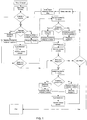
- an object to be printed begins as a three dimensional model and is sliced into multiple two dimensional slices which can be oriented parallel to and above the build plate 10.
- a first slice is selected. If a first material is required within this slice, first material powder and binder are applied, in either order, to cause the first material powder to be bound where required within the layer. Binding can be accelerated by curing, such as through a radiation source. Excess first material powder is removed. If the layer requires a second material, this process is repeated, but with a second material. The process can also be repeated with a third material (and potentially other additional materials).
- voids are required in the layer/slice, they can be filled with a fugitive material.
- a next slice of the object to be printed is used to control a repeat of the process, but with the geometry required for the second slice. The process continues until the last slice is fully printed.
- the object is finished by heating, such as to a sintering temperature to sinter the powders together, and with sufficient heat to cause fugitive material to volatilize and leave behind a void within the object.
- the present invention first provides a build plate 10 upon which the 3D printing of the object is carrier out.
- the object is built up in layers of powder material, bound together by a binder material delivered in a computer controlled pattern by an inkjet type print head 150.
- Figure 2 illustrates an example of a partially completed object, with four completed layers, each comprised of a first material 20, and a second material 30, and two of those four completed layers, further having regions containing no printed material 80. Such voids could be left open or could be filled with layers of fugitive material to facilitate printing over the voids in subsequent layers.
- Figures 2-8 depict the creation of a fifth complete layer.
- a powder dispersal mechanism 110 provides one form of dispenser that dispenses a layer of a first powder 60 over all of the completed portion of the printed object, including over the region 50 of the second material 30 and into the trench 80 where no printed material exists on the third or fourth completed layers.
- the powder dispersal mechanism comprises of a powder reservoir 100, a powder agitator/conditioner 90 and a dispersal head 40.
- the dispersal head may contain valves that allow for computer controlled opening to dispense the first powder only on selected areas.
- the powder dispersal mechanism traverses the entire length of the build plate from a first end to a second end opposite the first end, at a rate chosen to dispense a uniform layer of the first powder 60 of the desired thickness.
- the layer of the first powder 60 has been dispersed over the entire exposed surface of the partially printed object, and the multi nozzle print head 150 has traversed across a portion of the object from left to right in the illustration.
- the computer controls the operation of each of the nozzles in accordance with the design of the layer being printed. Specifically, the print head 150 dispenses binder material over its full width on the first edge 46 of the object and is then turned off completely as it traverses a left part 55 of the trench 80.
- FIG. 4 illustrates the object under construction as the print head 150 has traversed over the region 50 of the second material where the jets over the region 50 of the second material 30 are turned off, and only the jets over a first material 20 area of a center raised portion 161 are turned on.
- Figure 5 illustrates the object after binder has been jetted into all of the first material 20 intended to be a part of the fifth layer 47 and the binder has been cured and the excess powder 60 removed.
- the trench 80 is shown unshaded in this view to illustrate that the powder has been removed.
- the region 50 has also had powder removed but is shown with light shading. Removal could be by vacuuming or by sweeping or by blowing or by magnetic or static attraction for suitable materials, or by other removal techniques.
- Figure 6 illustrates the object under construction after a layer of a second powder 130 has been dispersed over the entire exposed surface of the partially completed object.
- the second powder 130 is dispersed with a second powder dispersal mechanism 111 ( Figure 9 ), similar to that used to disperse the first powder 60.
- the second powder 130 is dispersed over the entire upper surface of the object.
- This second powder 130 layer is multi-planar, with some second powder 130 placed upon the bound first powder 60 and some second powder 130 placed within the fifth layer of the object being printed.
- the second powder 130 that is placed upon the bound first powder 60 is not bound, but rather removed so that the sixth layer of the object can be printed on a flat surface (unless unfilled voids are present).
- the second powder 130 can be limited to not be placed where the bound first material 60 exists to avoid waste of second powder 130.
- Figure 7 illustrates the binder 162 jetting into the second powder 130 layer only over the second material region 50 of the object.
- the sequence of powder coating and binder jetting may be reversed for any, or all materials on any, or all layers, depending upon geometry and precision factors within a given design.
- Figure 8 illustrates the object under construction with the jetting of binder into the second powder 130 completed. Also, binder has been jetted into the trench 80 to add a layer of the second powder 130 thereto. The binder is cured, and the excess powder is removed, completing the completed fifth layer 47 of the object. It is noted that reference to first material layers and second material layers (and additional material layers) refers to sub-layers that can comprise a full layer of the object being printed, but most typically are only part of the completed layer which together, along with possible fugitive material, comprise a completed layer of the object.
- fugitive materials may be jetted directly into cavity areas within the object by a second, jetting type print head, specifically designed for the fugitive materials. Then, when a later sintering or other heating step is performed, the fugitive materials volatilize (into a gas typically), leaving a void/cavity in the object where called for by the design.
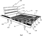
- Figure 9 illustrates the major portions of the present invention in a perspective form.
- the build plate 10 provides a foundation for starting the 3D printing of the array 15 of objects to be built. While a single object could be formed, in this embodiment multiple objects are simultaneously formed which are shown as identical but could be different.
- the build platform 10 itself is mounted on an elevator system 210 to allow the top of the completed layers to be indexed optimally with respect to the powder dispersal mechanism 110 and the print head 150, for each new layer, such as by moving down from an active printing plane after each layer is completed. All of the other major components of the present invention are in this embodiment mounted, either directly or indirectly, to a major axis transport mechanism 170 which itself is attached to a frame of the printer.
- the major axis transport mechanism 170 provides one form of a means to traverse a powder dispersal mechanism 110, 111, 112, the print head 150 (through a minor axis transport mechanism 180 associated therewith), curing radiation source 190 (or other binder accelerant), and the excess powder removal system 200 (such as a vacuum), across the top surface of the array of objects 15, in a highly controlled manner by the computer interpreting the CAD file (or other control). For instance, translating clamps on each mechanism 170 can selectively grab ends of one (or more) of these components and together advance the component(s) over the array 15 and then back to a dock for release by the clamps and selection of other components to traverse the active printing plane above the build plate.
- the powder dispersal system 109 is comprised of two or more powder dispersal mechanisms 110, 111, 112, that are in this embodiment arranged in a magazine system, such as an elevator 220, that allows the computer (or other control) to select the powder dispersal mechanism that contains the proper powder material for the current layer and region of the object array to be printed, and to be engaged with the major axis transport mechanism 170. Once engaged with the transport mechanism 170, the powder dispersal mechanism 110, 111, 112 can be traversed across the length of the build plate 10, preferably at a precisely controlled powder delivery rate.
- the powder dispersal mechanism 110, 111, 112 will also incorporate a series of valves that control the locations across the width of the powder dispersal mechanism 110, 111, 112, where powder is dispensed onto the array of objects under construction. Said valves will be controlled to dispense the minimum amount of powder material to form the regions intended for the given material and layer.
- the powder can either be dispensed over the entire surface or only over selected regions.
- the print head 150 is itself attached to the minor axis transport mechanism 180, such that, under the control of the computer, the print head can be traversed to any location across the width of the build plate 10.
- the minor axis transport mechanism 180 is itself engaged with the major axis transport mechanism 170, such that under control, the minor axis transport mechanism 180 may traverse the full length of the build plate 10. In this way, the print head 150 can be moved to any location above the build plate 10, and in any pattern of movement in the x-y plane.
- the print head 150 could be as wide as the minor axis transport mechanism 180 so it would not need to move relative to the mechanism 180.
- a curing radiation source 190 is engaged with the major axis transport mechanism 170, such that the curing radiation source 190 may traverse the entire length of the build plate 10.
- the radiation curing source 190 constitutes a series of UV LEDS, individually addressable by the computer.
- the radiation curing source 190 constitutes an IR source, capable of curing the binder in a very short time.
- the curing radiation source 190 constitutes a UV source, a fraction of the width of the build platform, engaged with a second minor axis transport mechanism 180, which is in turn engaged with the major axis transport mechanism 170, such that the UV source may be traversed to any point above the build plate 10, and traversed at a desired rate.
- the curing radiation source constitutes a wide area UV or IR source (typically stationary or only movable vertically) that illuminates the entire active printing plane above the surface of the build plate 10 at the same time.
- the wide area UV or IR source may be fixed in location above the build plate 10, arranged such that the powder dispersal mechanisms 110, 111, 112, the print head 150, and the excess powder removal system 200 may traverse the build plate 10 under the radiation source.
- the wide area UV or IR curing radiation source may be movable such that it can move to a location directly above the build plate during the curing step, and remove to an out-of-the-way location during the remainder of the 3D printing operation.
- the excess powder removal system 200 constitutes a high volume vacuum head, extending the full width of the build plate 10. Said excess powder removal system is engaged with the major axis transport system 170, to allow the excess powder removal system 200 to traverse the full length of the build plate 10, to vacuum up any powder that is not coated with binder and cured.
- a separate excess powder removal system is provided for each of the powder dispersal mechanisms 110, 111, 1112 in order to keep the several materials separated and minimize (or even eliminate) the purification or refurbishment of the excess powder before it is reintroduced to the process.
- the several excess powder removal systems are affixed to the corresponding powder dispersal mechanism 110, 111, 112. If high purity is not required, vacuumed powder can thus be immediately reused. Alternatively, the recycling/refurbishment process for each mechanism 110, 111, 112 is kept substantially limited to a single type of powder.
- This invention exhibits industrial applicability in that it provides a mechanism for three dimensional printing of objects comprised of more than one material or composite material.
- Another object of the present invention is to provide a binder jetting type of three dimensional printer capable of incorporating regions of different materials in a 3D printed object.
- Another object of the present invention is to provide a binder jetting type of 3D printer that has the capability of creating highly controlled layers of several different materials.
- Another object of the present invention is to provide a 3D printer with the capability of embedding regions of fugitive materials within an object comprised largely of robust, enduring materials, so the fugitive materials can be later turned into voids in the object.
- Another object of the present invention is to provide a 3D printer with the capability of embedding voids within an object comprised largely of robust, enduring materials, while there is only a tortured path, or no path at all from the empty voids to the outside surface of the printed object.
- Another object of the present invention is to provide a means for creating 3D objects, directly from computer design data, from high performance engineering materials rather than materials chosen to work with a specific 3D printer process.
- Another object of the present invention is to provide a 3D printer that has build rates that are high enough to be cost competitive with conventional methods of creating objects comprised of multiple materials and void regions within the structure.
Landscapes
- Chemical & Material Sciences (AREA)
- Engineering & Computer Science (AREA)
- Materials Engineering (AREA)
- Manufacturing & Machinery (AREA)
- Physics & Mathematics (AREA)
- Mechanical Engineering (AREA)
- Optics & Photonics (AREA)
- Coating Apparatus (AREA)
- Producing Shaped Articles From Materials (AREA)
- Powder Metallurgy (AREA)
Applications Claiming Priority (2)
| Application Number | Priority Date | Filing Date | Title |
|---|---|---|---|
| US201461988266P | 2014-05-04 | 2014-05-04 | |
| PCT/US2015/000056 WO2015171182A1 (en) | 2014-05-04 | 2015-05-04 | Multi-material three dimensional printer |
Publications (3)
| Publication Number | Publication Date |
|---|---|
| EP3140103A1 EP3140103A1 (en) | 2017-03-15 |
| EP3140103A4 EP3140103A4 (en) | 2018-04-04 |
| EP3140103B1 true EP3140103B1 (en) | 2020-01-08 |
Family
ID=54354579
Family Applications (1)
| Application Number | Title | Priority Date | Filing Date |
|---|---|---|---|
| EP15789216.7A Active EP3140103B1 (en) | 2014-05-04 | 2015-05-04 | Multi-material three dimensional printer |
Country Status (5)
| Country | Link |
|---|---|
| US (1) | US9604411B2 (enExample) |
| EP (1) | EP3140103B1 (enExample) |
| JP (1) | JP2017524579A (enExample) |
| CN (1) | CN106804106A (enExample) |
| WO (1) | WO2015171182A1 (enExample) |
Families Citing this family (79)
| Publication number | Priority date | Publication date | Assignee | Title |
|---|---|---|---|---|
| US9776376B2 (en) | 2011-08-29 | 2017-10-03 | Impossible Objects, LLC | Methods and apparatus for three-dimensional printed composites based on flattened substrate sheets |
| US9833949B2 (en) | 2011-08-29 | 2017-12-05 | Impossible Objects, Inc. | Apparatus for fabricating three-dimensional printed composites |
| US10343243B2 (en) | 2013-02-26 | 2019-07-09 | Robert Swartz | Methods and apparatus for construction of machine tools |
| CN106536165B (zh) * | 2014-07-09 | 2020-10-13 | 应用材料公司 | 增材制造中的层状加热、线状加热、等离子体加热及多重馈给材料 |
| WO2016109111A1 (en) * | 2014-12-30 | 2016-07-07 | Smith International, Inc. | Variable density, variable composition or complex geometry components for high pressure presses made by additive manufacturing methods |
| DE102015207158A1 (de) * | 2015-04-20 | 2016-10-20 | Eos Gmbh Electro Optical Systems | Verfahren und Vorrichtung zum Herstellen eines dreidimensionalen Objekts |
| US10946473B2 (en) * | 2015-05-14 | 2021-03-16 | General Electric Company | Additive manufacturing on 3-D components |
| CN118023550A (zh) | 2015-11-17 | 2024-05-14 | 因帕瑟伯物体公司 | 用于生产增材制造的金属基复合材料的装置和方法及其制品 |
| KR20190019899A (ko) | 2016-02-12 | 2019-02-27 | 임파서블 오브젝츠 엘엘씨 | 자동화된 복합체 기반 적층 가공 방법 및 장치 |
| GB201603351D0 (en) | 2016-02-26 | 2016-04-13 | Rolls Royce Plc | Additive layer manufacturing |
| GB2548340A (en) | 2016-03-09 | 2017-09-20 | Digital Metal Ab | Manufacturing method and manufacturing apparatus |
| US20170297102A1 (en) * | 2016-04-14 | 2017-10-19 | Desktop Metal, Inc. | Removable sinter supports |
| BR112018072364B1 (pt) | 2016-05-12 | 2022-05-17 | Hewlett-Packard Development Company, L.P. | Impressora tridimensional, método e mídia não transitória legível por computador |
| US9987682B2 (en) | 2016-08-03 | 2018-06-05 | 3Deo, Inc. | Devices and methods for three-dimensional printing |
| EP4342605A3 (en) | 2016-08-03 | 2024-08-14 | 3Deo, Inc. | Devices and methods for three-dimensional printing |
| US10946592B2 (en) | 2016-09-11 | 2021-03-16 | Impossible Objects, Inc. | Resistive heating-compression method and apparatus for composite-based additive manufacturing |
| CA3031403A1 (en) * | 2016-09-21 | 2018-03-29 | Sergey SINGOV | 3d printer |
| EP3338916A1 (de) * | 2016-12-22 | 2018-06-27 | HILTI Aktiengesellschaft | Verfahren zur schichtweisen fertigung eines bauteils aus pulverförmigem werkstoff |
| US20180186073A1 (en) * | 2017-01-03 | 2018-07-05 | General Electric Company | Additive manufacturing systems including a particulate dispenser and methods of operating such systems |
| US11148358B2 (en) * | 2017-01-03 | 2021-10-19 | General Electric Company | Methods and systems for vacuum powder placement in additive manufacturing systems |
| BR112019010426A2 (pt) * | 2017-02-24 | 2019-09-03 | Hewlett-Packard Development Company, L.P. | impressão tridimensional (3d) |
| US11577316B2 (en) | 2017-02-24 | 2023-02-14 | Hewlett-Packard Development Company, L.P. | Three-dimensional printing |
| EP3615248A1 (en) | 2017-04-26 | 2020-03-04 | The University Of Manchester | Apparatus for and process of additive manufacturing |
| US11123796B2 (en) | 2017-04-28 | 2021-09-21 | General Electric Company | Method of making a pre-sintered preform |
| WO2019017896A1 (en) * | 2017-07-18 | 2019-01-24 | Hewlett-Packard Development Company, L.P. | ADDITIVE MANUFACTURING METHOD FOR CAMOUFLING PHYSICAL CHARACTERISTICS OF AN ARTICLE |
| FR3070135B1 (fr) * | 2017-08-18 | 2019-08-16 | S.A.S 3Dceram-Sinto | Procede et machine de fabrication de pieces en materiau ceramique ou metallique par la technique des procedes additifs |
| US11420384B2 (en) * | 2017-10-03 | 2022-08-23 | General Electric Company | Selective curing additive manufacturing method |
| US11351724B2 (en) | 2017-10-03 | 2022-06-07 | General Electric Company | Selective sintering additive manufacturing method |
| EP3476570A1 (en) | 2017-10-25 | 2019-05-01 | Nederlandse Organisatie voor toegepast- natuurwetenschappelijk onderzoek TNO | Method and apparatus for making tangible products by layer wise manufacturing |
| GB2567877A (en) * | 2017-10-27 | 2019-05-01 | Xaar 3D Ltd | Apparatus and method for the manufacture of three-dimensional objects |
| US11590691B2 (en) | 2017-11-02 | 2023-02-28 | General Electric Company | Plate-based additive manufacturing apparatus and method |
| US11254052B2 (en) | 2017-11-02 | 2022-02-22 | General Electric Company | Vatless additive manufacturing apparatus and method |
| FR3074800B1 (fr) * | 2017-12-11 | 2019-11-01 | S.A.S 3Dceram-Sinto | Procede de fabrication de pieces en materiau ceramique par la technique des procedes additifs |
| JP6977537B2 (ja) * | 2017-12-19 | 2021-12-08 | セイコーエプソン株式会社 | 三次元造形物の製造方法 |
| US11085473B2 (en) * | 2017-12-22 | 2021-08-10 | Divergent Technologies, Inc. | Methods and apparatus for forming node to panel joints |
| US11090724B2 (en) * | 2017-12-28 | 2021-08-17 | Applied Materials, Inc. | Additive manufacturing with powder dispensing |
| DE102018200010A1 (de) * | 2018-01-02 | 2019-07-04 | Ford Global Technologies, Llc | Additives Fertigungsverfahren |
| US10821669B2 (en) | 2018-01-26 | 2020-11-03 | General Electric Company | Method for producing a component layer-by-layer |
| US10821668B2 (en) | 2018-01-26 | 2020-11-03 | General Electric Company | Method for producing a component layer-by- layer |
| CA3042670C (en) | 2018-05-08 | 2025-09-02 | 9328 8082 Quebec Inc | Modular additive manufacturing system and related methods for continuous part production |
| US11273608B2 (en) * | 2018-06-07 | 2022-03-15 | Sakuu Corporation | Multi-material three-dimensional printer |
| US10814552B2 (en) * | 2018-09-28 | 2020-10-27 | The Boeing Company | Powder dispensing unit, powder spreading unit, and a vibratory compaction system of an additive manufacturing system and methods therefor |
| JP7500081B2 (ja) * | 2018-10-08 | 2024-06-17 | サクウ コーポレーション | 3次元物体、3次元付加製造システム及び3次元物体の製造方法 |
| WO2020081058A1 (en) | 2018-10-16 | 2020-04-23 | Hewlett-Packard Development Company, L.P. | Material dispensing apparatus |
| US12115583B2 (en) * | 2018-11-08 | 2024-10-15 | Divergent Technologies, Inc. | Systems and methods for adhesive-based part retention features in additively manufactured structures |
| GB2579638B (en) * | 2018-12-07 | 2021-10-27 | Xaar 3D Ltd | Methods and apparatus for the manufacture of three-dimensional objects |
| GB2579639A (en) * | 2018-12-07 | 2020-07-01 | Xaar 3D Ltd | Sled configurations and methods of operation for the manufacture of three-dimensional objects |
| US11498283B2 (en) | 2019-02-20 | 2022-11-15 | General Electric Company | Method and apparatus for build thickness control in additive manufacturing |
| US11794412B2 (en) | 2019-02-20 | 2023-10-24 | General Electric Company | Method and apparatus for layer thickness control in additive manufacturing |
| US11179891B2 (en) | 2019-03-15 | 2021-11-23 | General Electric Company | Method and apparatus for additive manufacturing with shared components |
| DE102019112122A1 (de) * | 2019-05-09 | 2020-11-12 | Bayerische Motoren Werke Aktiengesellschaft | Verfahren zur additiven Herstellung eines Formkörpers |
| AT522763B1 (de) * | 2019-12-05 | 2021-01-15 | Metallconcept Gmbh | Druckkopf |
| EP4121241A4 (en) * | 2020-03-19 | 2023-12-13 | Michigan Technological University | SYSTEM AND METHOD FOR PRODUCING AN ARC WELDING ADDITIVE MANUFACTURING PART WITH GRANULAR SUPPORT |
| CN111497233A (zh) * | 2020-05-06 | 2020-08-07 | 深圳市光韵达增材制造研究院 | 一种双材料3d打印成型方法 |
| JP7781407B2 (ja) * | 2020-06-05 | 2025-12-08 | サクウ コーポレーション | ジェットバインダ印刷システム |
| EP4161718A4 (en) * | 2020-06-08 | 2024-05-29 | Hewlett-Packard Development Company, L.P. | Layer-by-layer solvent evaporation |
| US12275190B2 (en) | 2020-06-09 | 2025-04-15 | Periodot Print Llc | Build material extraction |
| US11806941B2 (en) | 2020-08-21 | 2023-11-07 | Divergent Technologies, Inc. | Mechanical part retention features for additively manufactured structures |
| EP3981528B1 (en) * | 2020-10-08 | 2025-11-26 | Peridot Print LLC | Air-permeable platforms for additive manufacturing |
| US11707883B2 (en) | 2020-11-20 | 2023-07-25 | General Electric Company | Foil interaction device for additive manufacturing |
| KR102343820B1 (ko) * | 2020-11-23 | 2021-12-28 | 주식회사 에스에프에스 | 프린팅 영역 가변형 3차원 프린팅 시스템 |
| US11865780B2 (en) | 2021-02-26 | 2024-01-09 | General Electric Company | Accumalator assembly for additive manufacturing |
| US11241742B1 (en) | 2021-03-31 | 2022-02-08 | Sakuu Corporation | Multi-material three-dimensional printer with underlying adjustable binder |
| CN117120245A (zh) * | 2021-03-31 | 2023-11-24 | 萨库公司 | 具有可调节粘合剂底层的多材料三维打印机 |
| WO2022212676A1 (en) * | 2021-03-31 | 2022-10-06 | Sakuu Corporation | Multi-material three-dimensional printer with underlying adjustable binder |
| JP2024513701A (ja) | 2021-03-31 | 2024-03-27 | サクウ コーポレーション | 多材料三次元プリンタおよび三次元物体を製造する方法 |
| US12005642B2 (en) | 2021-06-04 | 2024-06-11 | Stratasys Powder Production Ltd. | Sled configurations and methods of operation for the manufacture of three-dimensional objects |
| US11951679B2 (en) | 2021-06-16 | 2024-04-09 | General Electric Company | Additive manufacturing system |
| US11731367B2 (en) | 2021-06-23 | 2023-08-22 | General Electric Company | Drive system for additive manufacturing |
| US11958250B2 (en) | 2021-06-24 | 2024-04-16 | General Electric Company | Reclamation system for additive manufacturing |
| US11958249B2 (en) | 2021-06-24 | 2024-04-16 | General Electric Company | Reclamation system for additive manufacturing |
| US11826950B2 (en) | 2021-07-09 | 2023-11-28 | General Electric Company | Resin management system for additive manufacturing |
| US12172379B2 (en) | 2021-08-11 | 2024-12-24 | General Electric Company | Cleaning system for additive manufacturing |
| US12370741B2 (en) | 2021-08-13 | 2025-07-29 | General Electric Company | Material deposition assembly for additive manufacturing |
| US12296535B2 (en) | 2021-08-24 | 2025-05-13 | General Electric Company | Attachment structure for additive manufacturing |
| US11813799B2 (en) | 2021-09-01 | 2023-11-14 | General Electric Company | Control systems and methods for additive manufacturing |
| FR3130660B1 (fr) * | 2021-12-16 | 2024-11-08 | Safran Additive Mfg Campus | Procédé de fabrication additive sur lit de poudre |
| EP4249216A1 (en) | 2022-03-23 | 2023-09-27 | General Electric Company | Systems and methods for additive manufacturing |
| US12403654B2 (en) | 2022-09-30 | 2025-09-02 | General Electric Company | Systems and methods for additive manufacturing |
Family Cites Families (20)
| Publication number | Priority date | Publication date | Assignee | Title |
|---|---|---|---|---|
| US5204055A (en) * | 1989-12-08 | 1993-04-20 | Massachusetts Institute Of Technology | Three-dimensional printing techniques |
| US6280771B1 (en) * | 1997-02-20 | 2001-08-28 | Therics, Inc. | Dosage forms exhibiting multi-phasic release kinetics and methods of manufacture thereof |
| US5660621A (en) * | 1995-12-29 | 1997-08-26 | Massachusetts Institute Of Technology | Binder composition for use in three dimensional printing |
| US6363606B1 (en) * | 1998-10-16 | 2002-04-02 | Agere Systems Guardian Corp. | Process for forming integrated structures using three dimensional printing techniques |
| JP2001334581A (ja) * | 2000-05-24 | 2001-12-04 | Minolta Co Ltd | 三次元造形装置 |
| US6471800B2 (en) * | 2000-11-29 | 2002-10-29 | Nanotek Instruments, Inc. | Layer-additive method and apparatus for freeform fabrication of 3-D objects |
| JP2002307562A (ja) * | 2001-02-07 | 2002-10-23 | Minolta Co Ltd | 三次元造形装置、および三次元造形方法 |
| US20040084814A1 (en) * | 2002-10-31 | 2004-05-06 | Boyd Melissa D. | Powder removal system for three-dimensional object fabricator |
| US7829000B2 (en) * | 2005-02-25 | 2010-11-09 | Hewlett-Packard Development Company, L.P. | Core-shell solid freeform fabrication |
| CN100404174C (zh) * | 2006-01-24 | 2008-07-23 | 华中科技大学 | 一种快速制造功能梯度材料的制备方法 |
| JP5363313B2 (ja) * | 2006-05-12 | 2013-12-11 | マース インコーポレーテッド | 物体、ウェブまたはシート上に画像を形成するための粉末の使用 |
| US20080018018A1 (en) * | 2006-07-20 | 2008-01-24 | Nielsen Jeffrey A | Solid freeform fabrication methods and systems |
| JP4888236B2 (ja) * | 2007-06-08 | 2012-02-29 | セイコーエプソン株式会社 | 三次元造形装置、および三次元造形方法 |
| KR20120104563A (ko) * | 2009-12-30 | 2012-09-21 | 신세스 게엠바하 | 통합형 다중재료 임플란트 및 제조 방법 |
| CN202062079U (zh) * | 2011-03-29 | 2011-12-07 | 华南理工大学 | 一种直接制造梯度材料零件的装置 |
| EP2797730B2 (en) * | 2011-12-28 | 2020-03-04 | Arcam Ab | Method and apparatus for detecting defects in freeform fabrication |
| US10189086B2 (en) * | 2011-12-28 | 2019-01-29 | Arcam Ab | Method and apparatus for manufacturing porous three-dimensional articles |
| JP5772668B2 (ja) * | 2012-03-08 | 2015-09-02 | カシオ計算機株式会社 | 3次元造形方法及び造形物複合体並びに3次元造形装置 |
| JP2015112845A (ja) * | 2013-12-13 | 2015-06-22 | セイコーエプソン株式会社 | 三次元造形物製造装置、三次元造形物の製造方法および三次元造形物 |
| US9427773B2 (en) * | 2014-08-25 | 2016-08-30 | Solidscape, Inc. | Method for simultaneously scribing and filling of scribed channel, trough, trench or groove |
-
2015
- 2015-05-04 EP EP15789216.7A patent/EP3140103B1/en active Active
- 2015-05-04 WO PCT/US2015/000056 patent/WO2015171182A1/en not_active Ceased
- 2015-05-04 CN CN201580036582.1A patent/CN106804106A/zh active Pending
- 2015-05-04 US US14/702,946 patent/US9604411B2/en not_active Expired - Fee Related
- 2015-05-04 JP JP2017511142A patent/JP2017524579A/ja active Pending
Non-Patent Citations (1)
| Title |
|---|
| None * |
Also Published As
| Publication number | Publication date |
|---|---|
| WO2015171182A1 (en) | 2015-11-12 |
| EP3140103A4 (en) | 2018-04-04 |
| CN106804106A (zh) | 2017-06-06 |
| US20150314530A1 (en) | 2015-11-05 |
| US9604411B2 (en) | 2017-03-28 |
| EP3140103A1 (en) | 2017-03-15 |
| JP2017524579A (ja) | 2017-08-31 |
Similar Documents
| Publication | Publication Date | Title |
|---|---|---|
| EP3140103B1 (en) | Multi-material three dimensional printer | |
| US11090724B2 (en) | Additive manufacturing with powder dispensing | |
| US11980941B2 (en) | Method and apparatus for additive manufacturing with powder material | |
| KR102356021B1 (ko) | 3차원 적층 제조 시스템 및 3차원 물체를 제조하는 방법 | |
| CN108778685B (zh) | 制造方法和制造装置 | |
| US9469074B2 (en) | Method and device for conveying particulate material during the layer-wise production of patterns | |
| EP3181333B1 (en) | Method of manufacturing three-dimensionally formed object | |
| US20120133080A1 (en) | Additive Manufacturing Methods for Improved Curl Control and Sidewall Quality | |
| KR20160102420A (ko) | 가속화된 처리 속도로 3차원 프린팅을 수행하기 위한 방법 및 장치 | |
| US20190270136A1 (en) | Apparatus and method for selective material fusion three-dimensional (3d) printing | |
| KR20210152049A (ko) | 3차원 적층 제조 시스템 및 3차원 물체를 제조하는 방법 | |
| EP3296901B1 (en) | Three-dimensional modeling apparatus, method, and computer program | |
| EP3238864B1 (en) | Apparatus and method for fabricating three-dimensional objects | |
| JP6296448B2 (ja) | 造形ユニットおよび三次元積層造形装置 | |
| EP3981528B1 (en) | Air-permeable platforms for additive manufacturing | |
| EP3763462A1 (en) | A binder jet printer and method therefor |
Legal Events
| Date | Code | Title | Description |
|---|---|---|---|
| STAA | Information on the status of an ep patent application or granted ep patent |
Free format text: STATUS: THE INTERNATIONAL PUBLICATION HAS BEEN MADE |
|
| PUAI | Public reference made under article 153(3) epc to a published international application that has entered the european phase |
Free format text: ORIGINAL CODE: 0009012 |
|
| STAA | Information on the status of an ep patent application or granted ep patent |
Free format text: STATUS: REQUEST FOR EXAMINATION WAS MADE |
|
| 17P | Request for examination filed |
Effective date: 20161129 |
|
| AK | Designated contracting states |
Kind code of ref document: A1 Designated state(s): AL AT BE BG CH CY CZ DE DK EE ES FI FR GB GR HR HU IE IS IT LI LT LU LV MC MK MT NL NO PL PT RO RS SE SI SK SM TR |
|
| AX | Request for extension of the european patent |
Extension state: BA ME |
|
| DAV | Request for validation of the european patent (deleted) | ||
| DAX | Request for extension of the european patent (deleted) | ||
| A4 | Supplementary search report drawn up and despatched |
Effective date: 20180307 |
|
| RIC1 | Information provided on ipc code assigned before grant |
Ipc: B29C 64/20 20170101AFI20180301BHEP Ipc: B33Y 30/00 20150101ALI20180301BHEP Ipc: B33Y 50/02 20150101ALI20180301BHEP Ipc: B29C 64/165 20170101ALI20180301BHEP |
|
| RAP1 | Party data changed (applicant data changed or rights of an application transferred) |
Owner name: EOPLEX LIMITED |
|
| REG | Reference to a national code |
Ref country code: DE Ref legal event code: R079 Ref document number: 602015045231 Country of ref document: DE Free format text: PREVIOUS MAIN CLASS: B29C0067000000 Ipc: B29C0064200000 |
|
| RIC1 | Information provided on ipc code assigned before grant |
Ipc: B33Y 30/00 20150101ALI20190619BHEP Ipc: B33Y 50/02 20150101ALI20190619BHEP Ipc: B29C 64/20 20170101AFI20190619BHEP Ipc: B29C 64/165 20170101ALI20190619BHEP |
|
| GRAP | Despatch of communication of intention to grant a patent |
Free format text: ORIGINAL CODE: EPIDOSNIGR1 |
|
| STAA | Information on the status of an ep patent application or granted ep patent |
Free format text: STATUS: GRANT OF PATENT IS INTENDED |
|
| INTG | Intention to grant announced |
Effective date: 20190821 |
|
| GRAS | Grant fee paid |
Free format text: ORIGINAL CODE: EPIDOSNIGR3 |
|
| GRAA | (expected) grant |
Free format text: ORIGINAL CODE: 0009210 |
|
| STAA | Information on the status of an ep patent application or granted ep patent |
Free format text: STATUS: THE PATENT HAS BEEN GRANTED |
|
| AK | Designated contracting states |
Kind code of ref document: B1 Designated state(s): AL AT BE BG CH CY CZ DE DK EE ES FI FR GB GR HR HU IE IS IT LI LT LU LV MC MK MT NL NO PL PT RO RS SE SI SK SM TR |
|
| REG | Reference to a national code |
Ref country code: GB Ref legal event code: FG4D |
|
| REG | Reference to a national code |
Ref country code: CH Ref legal event code: EP |
|
| REG | Reference to a national code |
Ref country code: DE Ref legal event code: R096 Ref document number: 602015045231 Country of ref document: DE |
|
| REG | Reference to a national code |
Ref country code: IE Ref legal event code: FG4D |
|
| REG | Reference to a national code |
Ref country code: AT Ref legal event code: REF Ref document number: 1222158 Country of ref document: AT Kind code of ref document: T Effective date: 20200215 |
|
| REG | Reference to a national code |
Ref country code: NL Ref legal event code: MP Effective date: 20200108 |
|
| REG | Reference to a national code |
Ref country code: LT Ref legal event code: MG4D |
|
| PG25 | Lapsed in a contracting state [announced via postgrant information from national office to epo] |
Ref country code: NL Free format text: LAPSE BECAUSE OF FAILURE TO SUBMIT A TRANSLATION OF THE DESCRIPTION OR TO PAY THE FEE WITHIN THE PRESCRIBED TIME-LIMIT Effective date: 20200108 Ref country code: LT Free format text: LAPSE BECAUSE OF FAILURE TO SUBMIT A TRANSLATION OF THE DESCRIPTION OR TO PAY THE FEE WITHIN THE PRESCRIBED TIME-LIMIT Effective date: 20200108 Ref country code: RS Free format text: LAPSE BECAUSE OF FAILURE TO SUBMIT A TRANSLATION OF THE DESCRIPTION OR TO PAY THE FEE WITHIN THE PRESCRIBED TIME-LIMIT Effective date: 20200108 Ref country code: PT Free format text: LAPSE BECAUSE OF FAILURE TO SUBMIT A TRANSLATION OF THE DESCRIPTION OR TO PAY THE FEE WITHIN THE PRESCRIBED TIME-LIMIT Effective date: 20200531 Ref country code: NO Free format text: LAPSE BECAUSE OF FAILURE TO SUBMIT A TRANSLATION OF THE DESCRIPTION OR TO PAY THE FEE WITHIN THE PRESCRIBED TIME-LIMIT Effective date: 20200408 Ref country code: FI Free format text: LAPSE BECAUSE OF FAILURE TO SUBMIT A TRANSLATION OF THE DESCRIPTION OR TO PAY THE FEE WITHIN THE PRESCRIBED TIME-LIMIT Effective date: 20200108 |
|
| PGFP | Annual fee paid to national office [announced via postgrant information from national office to epo] |
Ref country code: DE Payment date: 20200602 Year of fee payment: 6 |
|
| PG25 | Lapsed in a contracting state [announced via postgrant information from national office to epo] |
Ref country code: IS Free format text: LAPSE BECAUSE OF FAILURE TO SUBMIT A TRANSLATION OF THE DESCRIPTION OR TO PAY THE FEE WITHIN THE PRESCRIBED TIME-LIMIT Effective date: 20200508 Ref country code: GR Free format text: LAPSE BECAUSE OF FAILURE TO SUBMIT A TRANSLATION OF THE DESCRIPTION OR TO PAY THE FEE WITHIN THE PRESCRIBED TIME-LIMIT Effective date: 20200409 Ref country code: SE Free format text: LAPSE BECAUSE OF FAILURE TO SUBMIT A TRANSLATION OF THE DESCRIPTION OR TO PAY THE FEE WITHIN THE PRESCRIBED TIME-LIMIT Effective date: 20200108 Ref country code: LV Free format text: LAPSE BECAUSE OF FAILURE TO SUBMIT A TRANSLATION OF THE DESCRIPTION OR TO PAY THE FEE WITHIN THE PRESCRIBED TIME-LIMIT Effective date: 20200108 Ref country code: HR Free format text: LAPSE BECAUSE OF FAILURE TO SUBMIT A TRANSLATION OF THE DESCRIPTION OR TO PAY THE FEE WITHIN THE PRESCRIBED TIME-LIMIT Effective date: 20200108 Ref country code: BG Free format text: LAPSE BECAUSE OF FAILURE TO SUBMIT A TRANSLATION OF THE DESCRIPTION OR TO PAY THE FEE WITHIN THE PRESCRIBED TIME-LIMIT Effective date: 20200408 |
|
| REG | Reference to a national code |
Ref country code: DE Ref legal event code: R097 Ref document number: 602015045231 Country of ref document: DE |
|
| PG25 | Lapsed in a contracting state [announced via postgrant information from national office to epo] |
Ref country code: DK Free format text: LAPSE BECAUSE OF FAILURE TO SUBMIT A TRANSLATION OF THE DESCRIPTION OR TO PAY THE FEE WITHIN THE PRESCRIBED TIME-LIMIT Effective date: 20200108 Ref country code: ES Free format text: LAPSE BECAUSE OF FAILURE TO SUBMIT A TRANSLATION OF THE DESCRIPTION OR TO PAY THE FEE WITHIN THE PRESCRIBED TIME-LIMIT Effective date: 20200108 Ref country code: EE Free format text: LAPSE BECAUSE OF FAILURE TO SUBMIT A TRANSLATION OF THE DESCRIPTION OR TO PAY THE FEE WITHIN THE PRESCRIBED TIME-LIMIT Effective date: 20200108 Ref country code: SM Free format text: LAPSE BECAUSE OF FAILURE TO SUBMIT A TRANSLATION OF THE DESCRIPTION OR TO PAY THE FEE WITHIN THE PRESCRIBED TIME-LIMIT Effective date: 20200108 Ref country code: CZ Free format text: LAPSE BECAUSE OF FAILURE TO SUBMIT A TRANSLATION OF THE DESCRIPTION OR TO PAY THE FEE WITHIN THE PRESCRIBED TIME-LIMIT Effective date: 20200108 Ref country code: RO Free format text: LAPSE BECAUSE OF FAILURE TO SUBMIT A TRANSLATION OF THE DESCRIPTION OR TO PAY THE FEE WITHIN THE PRESCRIBED TIME-LIMIT Effective date: 20200108 Ref country code: SK Free format text: LAPSE BECAUSE OF FAILURE TO SUBMIT A TRANSLATION OF THE DESCRIPTION OR TO PAY THE FEE WITHIN THE PRESCRIBED TIME-LIMIT Effective date: 20200108 |
|
| PLBE | No opposition filed within time limit |
Free format text: ORIGINAL CODE: 0009261 |
|
| STAA | Information on the status of an ep patent application or granted ep patent |
Free format text: STATUS: NO OPPOSITION FILED WITHIN TIME LIMIT |
|
| REG | Reference to a national code |
Ref country code: AT Ref legal event code: MK05 Ref document number: 1222158 Country of ref document: AT Kind code of ref document: T Effective date: 20200108 |
|
| 26N | No opposition filed |
Effective date: 20201009 |
|
| PG25 | Lapsed in a contracting state [announced via postgrant information from national office to epo] |
Ref country code: IT Free format text: LAPSE BECAUSE OF FAILURE TO SUBMIT A TRANSLATION OF THE DESCRIPTION OR TO PAY THE FEE WITHIN THE PRESCRIBED TIME-LIMIT Effective date: 20200108 Ref country code: CH Free format text: LAPSE BECAUSE OF NON-PAYMENT OF DUE FEES Effective date: 20200531 Ref country code: LI Free format text: LAPSE BECAUSE OF NON-PAYMENT OF DUE FEES Effective date: 20200531 Ref country code: AT Free format text: LAPSE BECAUSE OF FAILURE TO SUBMIT A TRANSLATION OF THE DESCRIPTION OR TO PAY THE FEE WITHIN THE PRESCRIBED TIME-LIMIT Effective date: 20200108 Ref country code: MC Free format text: LAPSE BECAUSE OF FAILURE TO SUBMIT A TRANSLATION OF THE DESCRIPTION OR TO PAY THE FEE WITHIN THE PRESCRIBED TIME-LIMIT Effective date: 20200108 |
|
| PG25 | Lapsed in a contracting state [announced via postgrant information from national office to epo] |
Ref country code: PL Free format text: LAPSE BECAUSE OF FAILURE TO SUBMIT A TRANSLATION OF THE DESCRIPTION OR TO PAY THE FEE WITHIN THE PRESCRIBED TIME-LIMIT Effective date: 20200108 Ref country code: SI Free format text: LAPSE BECAUSE OF FAILURE TO SUBMIT A TRANSLATION OF THE DESCRIPTION OR TO PAY THE FEE WITHIN THE PRESCRIBED TIME-LIMIT Effective date: 20200108 |
|
| REG | Reference to a national code |
Ref country code: BE Ref legal event code: MM Effective date: 20200531 |
|
| GBPC | Gb: european patent ceased through non-payment of renewal fee |
Effective date: 20200504 |
|
| PG25 | Lapsed in a contracting state [announced via postgrant information from national office to epo] |
Ref country code: LU Free format text: LAPSE BECAUSE OF NON-PAYMENT OF DUE FEES Effective date: 20200504 |
|
| PG25 | Lapsed in a contracting state [announced via postgrant information from national office to epo] |
Ref country code: FR Free format text: LAPSE BECAUSE OF NON-PAYMENT OF DUE FEES Effective date: 20200531 Ref country code: IE Free format text: LAPSE BECAUSE OF NON-PAYMENT OF DUE FEES Effective date: 20200504 Ref country code: GB Free format text: LAPSE BECAUSE OF NON-PAYMENT OF DUE FEES Effective date: 20200504 |
|
| PG25 | Lapsed in a contracting state [announced via postgrant information from national office to epo] |
Ref country code: BE Free format text: LAPSE BECAUSE OF NON-PAYMENT OF DUE FEES Effective date: 20200531 |
|
| REG | Reference to a national code |
Ref country code: DE Ref legal event code: R119 Ref document number: 602015045231 Country of ref document: DE |
|
| PG25 | Lapsed in a contracting state [announced via postgrant information from national office to epo] |
Ref country code: DE Free format text: LAPSE BECAUSE OF NON-PAYMENT OF DUE FEES Effective date: 20211201 |
|
| PG25 | Lapsed in a contracting state [announced via postgrant information from national office to epo] |
Ref country code: TR Free format text: LAPSE BECAUSE OF FAILURE TO SUBMIT A TRANSLATION OF THE DESCRIPTION OR TO PAY THE FEE WITHIN THE PRESCRIBED TIME-LIMIT Effective date: 20200108 Ref country code: MT Free format text: LAPSE BECAUSE OF FAILURE TO SUBMIT A TRANSLATION OF THE DESCRIPTION OR TO PAY THE FEE WITHIN THE PRESCRIBED TIME-LIMIT Effective date: 20200108 Ref country code: CY Free format text: LAPSE BECAUSE OF FAILURE TO SUBMIT A TRANSLATION OF THE DESCRIPTION OR TO PAY THE FEE WITHIN THE PRESCRIBED TIME-LIMIT Effective date: 20200108 |
|
| PG25 | Lapsed in a contracting state [announced via postgrant information from national office to epo] |
Ref country code: MK Free format text: LAPSE BECAUSE OF FAILURE TO SUBMIT A TRANSLATION OF THE DESCRIPTION OR TO PAY THE FEE WITHIN THE PRESCRIBED TIME-LIMIT Effective date: 20200108 Ref country code: AL Free format text: LAPSE BECAUSE OF FAILURE TO SUBMIT A TRANSLATION OF THE DESCRIPTION OR TO PAY THE FEE WITHIN THE PRESCRIBED TIME-LIMIT Effective date: 20200108 |