EP3139731B1 - Milk tank system and method for cleaning this - Google Patents
Milk tank system and method for cleaning this Download PDFInfo
- Publication number
- EP3139731B1 EP3139731B1 EP15728210.4A EP15728210A EP3139731B1 EP 3139731 B1 EP3139731 B1 EP 3139731B1 EP 15728210 A EP15728210 A EP 15728210A EP 3139731 B1 EP3139731 B1 EP 3139731B1
- Authority
- EP
- European Patent Office
- Prior art keywords
- milk
- holder
- level
- switching
- milking
- Prior art date
- Legal status (The legal status is an assumption and is not a legal conclusion. Google has not performed a legal analysis and makes no representation as to the accuracy of the status listed.)
- Active
Links
Images

Classifications
-
- A—HUMAN NECESSITIES
- A01—AGRICULTURE; FORESTRY; ANIMAL HUSBANDRY; HUNTING; TRAPPING; FISHING
- A01J—MANUFACTURE OF DAIRY PRODUCTS
- A01J9/00—Milk receptacles
-
- A—HUMAN NECESSITIES
- A01—AGRICULTURE; FORESTRY; ANIMAL HUSBANDRY; HUNTING; TRAPPING; FISHING
- A01J—MANUFACTURE OF DAIRY PRODUCTS
- A01J5/00—Milking machines or devices
- A01J5/007—Monitoring milking processes; Control or regulation of milking machines
-
- A—HUMAN NECESSITIES
- A01—AGRICULTURE; FORESTRY; ANIMAL HUSBANDRY; HUNTING; TRAPPING; FISHING
- A01J—MANUFACTURE OF DAIRY PRODUCTS
- A01J5/00—Milking machines or devices
- A01J5/04—Milking machines or devices with pneumatic manipulation of teats
- A01J5/044—Milk lines or coupling devices for milk conduits
-
- A—HUMAN NECESSITIES
- A01—AGRICULTURE; FORESTRY; ANIMAL HUSBANDRY; HUNTING; TRAPPING; FISHING
- A01J—MANUFACTURE OF DAIRY PRODUCTS
- A01J7/00—Accessories for milking machines or devices
- A01J7/02—Accessories for milking machines or devices for cleaning or sanitising milking machines or devices
- A01J7/022—Clean-in-Place Systems, i.e. CIP, for cleaning the complete milking installation in place
-
- A—HUMAN NECESSITIES
- A01—AGRICULTURE; FORESTRY; ANIMAL HUSBANDRY; HUNTING; TRAPPING; FISHING
- A01J—MANUFACTURE OF DAIRY PRODUCTS
- A01J7/00—Accessories for milking machines or devices
- A01J7/02—Accessories for milking machines or devices for cleaning or sanitising milking machines or devices
- A01J7/027—Vessel cleaning, e.g. cleansing of milk tanks, milk vessels or milk separators
Definitions
- the present invention relates to a milk tank system
- a milk tank system comprising a first holder configured for intermediate storage of milk from several milkings of a milking device, a second holder for storage of milk from the first holder, a transport device for transporting milk which comprises a milk line from the first holder to the second holder, via which milk line the second holder may be brought into fluidic connection with the first holder, and a shut-off means for shutting off the fluidic connection, in particular from the first holder to the milk line, and wherein the transport device has a first operating state which is configured for collecting milk in the first holder, and a second operating state which is configured for transferring the milk from the first holder to the second holder.
- the first holder usually serves as a buffer tank for pumping milk to the milk tank, which is a second holder.
- a milk pump of a standard milking device is rarely sufficiently powerful to overcome the high line resistance of long main milk lines in large dairies without overloading the milk.
- the first holder does not comprise a milk glass such as is normal for many milking devices, including robot milking devices. During milking of successive animals, a milk glass will temporarily store milk from the successive milkings, but it is expressly intended that the first holder can store milk from several milkings simultaneously.
- the volume will then also be significantly greater than that of an average milk glass, and for example be at least 100 liters.
- the second holder usually means the milk tank in which milk is cooled and stored until the time of collection by a milk tanker. This milk tank often has a capacity of a few thousand liters, and in each case is many times larger than the first holder.
- the first holder In practice, the first holder is filled with milk from several milkings and is then emptied into the milk tank.
- One problem which arises is that the first holder (the buffer tank) is often difficult to clean, in particular in relation to caked milk fat.
- Document GB2303226A discloses a system to control the level of liquid in a receiving tank in a milking machine, with a pump that removes milk from the tank in a rate dependent upon the level of milk therein.
- the invention achieves this object with a milk tank system according to claim 1.
- the concept behind the present invention is that pumping of the milk out of the first holder does not always begin at the same milk level in the holder. However a layer of foam or milk fat, milk protein or similar always forms on the milk, residue from which may remain behind when the first holder is pumped out. If, as in the prior art, pumping always takes place at the same level, then an ever thicker and further hardening layer of milk fat will be deposited on the wall of the first holder at this level. By starting the pumping out at a level which changes over time, as in accordance with the present invention, this caking and hardening of the milk fat will take place to a far lesser extent. Subsequent cleaning of the first holder can then be carried out more easily and/or better.
- a switching milk level changeable over time means that the milk level at which switching between the two operating states takes place varies over time.
- the milk level itself will also vary over time on supply or discharge of milk, but the relevant factor for the invention is the switching milk level at which the operating state is switched.
- the transport of milk by the transport device here means either active or passive transport of milk.
- the latter includes transport under the influence of gravity, such as in pipes on a gradient and similar.
- Active milk transport comprises transport by means of a pump or similar. Combinations of the two transport types are also possible.
- the first operating state of the transport device here means that milk is captured and collected in the first holder without being able to flow to the second holder
- the second operating state means the state in which the milk can flow from the first holder to the second holder, again actively and/or passively.
- the switching milk level is non-decreasing during a time interval, and has a different value for at least two time points during the time interval.
- the time interval is selected such that the first holders are emptied at least twice on average. The selection of the time interval may be based on historic averages or similar. Also, in practice, the first holder is usually emptied more often than twice before it is cleaned, but this depends on the size of the dairy and the number of connected milking devices and similar. In said embodiments therefore, emptying of the first holder begins at a higher level each time. Therefore any caked milk residue from most "filling events" will be rinsed away at least partly on subsequent filling of the first holder.
- the switching milk level is strictly increasing at least during a time interval.
- the switching milk level is in each case higher than the present level. This ensures optimum rinsing of the milk fat rim, and hence as little caking of milk fat and similar as possible.
- the switching milk level changes arbitrarily at least during a time interval.
- the wall of the first holder will be loaded with the milk (fat) deposits as evenly as possible, so that thick deposits occur as little as possible.
- the switching milk level varies within a predefined bandwidth around the base value, and the base value has an increasing value during the time interval. In these embodiments, the switching milk level will gradually rise, but temporarily may vary within a relatively limited margin. These embodiments also are intended to minimize the local deposit load.
- the time interval has a predefined and in particular fixed value, and the switching milk level after expiry of the time interval is lower than a switching milk level during the time interval, and in particular equal to a lowest switching milk level during the time interval.
- a regime is applied so that the switching milk level may be reset.
- the switching milk level may not continue to rise unlimitedly.
- a cleaning interval time is set for the time interval. This is often set to eight hours, so that the first holder is cleaned three times per day. Also however other times are possible, such as for example on the basis of legal stipulations.
- Another example is a time period of for example two hours, within which period the milk obtained must be cooled to a lower temperature such as 4°C. If for example the first holder is then not yet filled to the switching milk level originally set, the system still switches from the first to the second operating state in order to empty the first holder. In all cases, after emptying, a different switching milk level may be set, wherein if the first holder is cleaned, the switching milk level is reset to the lowest base value, whereas after simply emptying the first holder, the switching milk level may be varied following previously set criteria, as discussed above.
- the time interval is taken from a first cleaning action of at least the first holder to a successive second cleaning action of at least the first holder.
- the time interval may be a time interval between two successive cleaning actions of the first holder. Also, during such a cleaning action, more than merely the first holder may be cleaned, i.e. also the transport device and/or the second holder. This has no influence on the switching milk level to be set.
- the milk system comprises a milk level determination device which is configured for determining a level of the milk in the first holder and for emitting a level signal on the basis of the milk level determined.
- the milk level determination device serves primarily for determining the milk level in order to switch the operating state on the basis thereof. Switching takes place by the control system produced to this end, on the basis of the level signal emitted.
- a milk level determination device may be a direct height meter, such as an array of photoelectric cells which is erected vertically in the first holder, a pressure meter or weight meter which determines the pressure or weight of the milk above it, etc.
- the milk level value may be determined indirectly on the basis of data concerning the quantity of milk obtained per milking device, which value may then be passed to the control system.
- the milking devices may comprise suitable devices such as milk flow meters, or meters which determine the weight of the milk glass. Other suitable meters are not however excluded.
- the milk level determination device may also comprise an array of sensors which indicates merely whether the milk level is higher or lower, such as an array of conductivity sensors. The switching milk level may then be set by selecting a highest of these sensors, wherein the operating state is switched when the milk level reaches the respective sensor. Other alternatives for a milk level determination device known in the prior art are not excluded here.
- the transport device comprises a pump controllable by the control system for transferring milk from the first holder via the milk line to the second holder.
- the milk transport may take place both passively and actively.
- the transport takes place actively by means of the controllable pump.
- the pump may comprise a pump system with two or more pumps.
- the pump or the pump system may be arranged on or below the first holder, for example just after this, in the milk line. This milk line is also often called the main milk line, to distinguish it from lines which run from the milking devices to the first holder.
- the pump In the first operating state, the pump is usually not functioning or is switched such that the milk is not pumped out of the first holder, while in the second operating state the pump can pump the milk to the second holder. This can be achieved by opening or closing valves for example. This will be evident to the person skilled in the art and will not be explained in more detail here.
- the control system is configured to switch back from the second to the first operating state at a return switching milk level of the milk in the first holder.
- a separate return switching milk level is set at which emptying of the first holder is stopped. This may be a zero level, but may also be another level. This may for example be desirable in order to empty the first holder more gradually. Rapid emptying of the first holder can load the milk mechanically, while slower emptying or stopping emptying at a return switching level higher than the zero level, wherein a lower emptying speed may be maintained, may lead to advantages for the milk quality.
- the return switching milk level is changeable over time.
- the return switching milk level is either a predefined level difference or a predefined percentage lower than the switching milk level.
- the first holder is therefore not necessarily fully emptied, but it is decided to allow a fixed quantity of milk to flow out of the first holder (predefined level difference) or a specific proportion thereof (predefined percentage). This can offer advantages when possibly pumping milk out of the first holder more gradually, with a resulting lower mechanical load.
- an intermediate milk storage vessel for use in a milk tank system according to the present invention, comprising a vessel for containing milk from several milkings, a supply for receiving the milk, a discharge for discharging the milk, and a pump system for pumping the milk from the vessel through the discharge, furthermore comprising a control system for switching the pump system from a first operating state to a second operating state at a temporally changeable switching milk level to be reached by the milk in the vessel.
- Such an intermediate milk storage vessel offers advantages in relation to cleaning thereof and hence also the achievable milk quality.
- Both the intermediate milk storage vessel and the milk tank system as a whole may also be fitted later, if for example a small dairy farm with for example one or two milking devices is extended into a much larger enterprise, wherein a first holder is desirable as a buffer tank and the line lengths increase.
- Furthermore such an intermediate milk storage vessel may also serve as a substitute for existing buffer vessels.
- the invention also relates to a milking system according to claim 13 comprising a plurality of milking devices, and to a milk tank system connected to the plurality of milking devices, according to the present invention.
- This aspect of the invention describes a complete milking system with a plurality of milking devices and a milk tank system according to the present invention, in which said advantages can be optimally achieved.
- the milking devices are robot milking devices.
- the invention also relates to a milking method according to claim 14, comprising obtaining the milk using at least one milking device, intermediately storing in a first holder, not being a milk glass, the milk obtained from several milkings without milk being able to flow to the second holder, determinating a milk level in the first holder, and connecting a transport device for transporting at least part of the stored milk from the first holder to a second holder when the milk level in the first holder reaches a switching milk level.
- This method comprises the switching milk level which is changeable over time, whereby the advantages described earlier in this application are achieved. Again, the particular features cited above and their advantages are not repeated, and these also apply to the method without restriction.
- the method comprises performing a cleaning action on the first holder, wherein the switching milk level between two successive cleaning actions of the first holder is a non-decreasing function, preferably a strictly increasing function, of time.
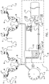
- FIG. 1 depicts a milking system 1 according to the invention in a highly diagrammatic view.
- the milking system 1 here comprises four milking robot devices 2 and a carousel 3.
- Each milking robot device 2 has milking cups 4 and a gripper arm 5 for placing the milking cups on the teats of a dairy animal.
- a milk glass 6 is also provided for capturing the milk from a milking, and a milking pump 7 for pumping the milk through the milk line 8 to a milk storage system 9, comprising an intermediate milk storage vessel 10 which is connected via a main milk line 11 to a milk tank 12 and which receives the milk 14.
- a control system is designated 13, a first discharge 21 and a second discharge 22 to an outlet capture unit 23 and a selection device 24.
- 25 indicates a pump system with a first pump 26 and a second pump 27.
- 30 indicates a sensor for the fluid quality, and 33 and 33' are milk level sensors.
- the milking system 1 shown here comprises a carousel 3 with a plurality of milking stands with milking cups 4, and also four milking robot devices 2. It is clear that the milking system may also comprise merely one carousel or a plurality of carousels, and also merely any number of milking robot devices such as two, eight, sixteen etc. Also, not all details relevant to the invention are shown, such as milking stands at the milking robot devices etc.
- Each milking robot device 2 is configured for milking a dairy animal at a milking stand (not shown). For this, using the gripper arm 5 or another suitable device, the milking robot device 2 places the milking cups 4 on the teats of the dairy animal. Here only two milking cups 4 are shown, which is sufficient for a goat or similar. For cows, four milking cups are required. The milk obtained with the milking cups 4 is captured per milking in the milk glass 6. The milking robot device 2 is furthermore configured to determine whether the milk from the milking, as consumption milk, should be transferred from the milk glass 6 to the milk tank 12.
- the milking robot device 2 has apparatus not shown here, such as a milk quality device or a management system which, for example on the basis of an established animal identity, can determine whether the milk is suitable or unsuitable for human consumption. If the milk is found to be unsuitable, a discharge (not shown here) of the milk is created from the milk glass 6 e.g. to a drain or to a residual milk capture unit. If the milk is found suitable for human consumption, it is pumped by the milk pump 7 from the milk glass 6 into the milk line system 8. The milk is then captured in the milk storage system 9, which here comprises an intermediate milk storage vessel 10.
- a milk quality device or a management system which, for example on the basis of an established animal identity, can determine whether the milk is suitable or unsuitable for human consumption. If the milk is found to be unsuitable, a discharge (not shown here) of the milk is created from the milk glass 6 e.g. to a drain or to a residual milk capture unit. If the milk is found suitable for human consumption, it is pumped by the milk pump
- the intermediate milk storage vessel 10 receives milk from several milkings, and for example - as shown here - milk from a plurality of milk glasses and/or from a carousel 3.
- the volume of the intermediate milk storage vessel 10 is then selected accordingly, and for example comprises a few hundred liters.
- the milk is pumped out by the pump system 25 through the main milk line 11 to the milk tank 12.
- This is controlled by the control system 13, which is here depicted only highly diagrammatically.
- Milk 14 is present in the milk storage vessel 10 to a specific level. This level may be determined with the milk level meter 33, 33'.
- the milk level meter 33, 33' may for example be a weighing cell which is arranged below the intermediate milk storage vessel 10, or alternatively or additionally an array of conductivity pins 33' arranged along the wall of the vessel 10, a pressure sensor etc.
- the milk level meter 33, 33' emits a specific signal which can be processed by the control system 13.
- the control system 13 may switch on the pump system 25 to lower the level of the milk 14 and pump the milk 14 to the milk tank 12 via the main milk line 11.
- Each milking device is cleaned after one or more milkings.
- all milking devices such as the milk robot devices 2 and the carousel 3, are cleaned in one cleaning action, either in parallel or sequentially or in combination.
- the pump system 25 here comprises a first pump 26 and a second pump 27.
- the pump system 25 may thus for example pump at several pump speeds, such as at a first pump speed set by the first pump 26 for pumping the milk, and at a second higher pump speed for pumping cleaning fluid using the second pump 27 or both pumps 26 and 27; this can also be achieved with a single controlled pump.
- FIG. 2 depicts schematically a diagram of the development of the level of the milk 14 in a storage vessel 10 according to a milking system of the prior art. It is evident here that at time t 0 , the milk level h m begins to rise from 0 until it reaches a height h max at time t 1 . At that moment, a pump system is switched on and the milk level begins to fall towards 0. The pump system is then switched off and the milk level begins to rise again until at time t 2 it has again reached the same level h max . The same cycle is repeated again from pumping out to 0, allowing the milk level to rise to h max and then pumping out again (such is now at time t 3 ). With such a system, pumping out always begins at the same maximum milk level, so that in a storage vessel, caking of for example milk fat or similar can occur at level h max . On the subsequent cleaning, this caking can be removed; however this is not always easy.
- Figure 3 in contrast shows a filling and pumping out regime according to the present invention.
- This again begins at time 0 with a milk level 0, which then rises until a height h m1 is reached at time t 1 , after which milk is pumped out to a stop level h s1 .
- the milk level rises again but now until at time t 2 , a height h m2 is reached after which pumping out takes place to a higher stop level h s2
- pumping out begins again at time t 3 , now until a stop level h s3 , and so on.
- Figure 4 depicts a diagrammatic example of milk levels to be reached in the intermediate milk storage vessel 10. For example, pumping out begins for the first time when milk level h 1 is reached. On the next filling of the storage vessel 10, the milk level can rise to level h 2 , then h 3 , then h 4 and then h 5 . After pumping from this last level, for example a cleaning of the intermediate storage vessel 10 may take place. It is noted that the levels h 1 to h 5 shown may in practice vary in number and in height relative to the intermediate milk storage vessel 10. For example there is no point in pumping out from a very low first level h 1 , because the number of pump cycles would become unnecessarily high.
- level h 1 may be at least three-quarters of the maximum milk level to be reached in the vessel 10. Nonetheless, any other ratio between the lowest pumping level and the highest pumping level is possible. This can be determined in practice, for example from the time between pumping actions.
- a great advantage of the present invention is that pumping out of the milk from the intermediate milk storage vessel 10 does not begin at the same or comparable maximum milk level, but preferably at an ever increasing level, so that any caked milk residue is in each case rinsed away on a following filling. Cleaning is then performed only at the (very) highest level, so that no caking problems occur.
Landscapes
- Life Sciences & Earth Sciences (AREA)
- Animal Husbandry (AREA)
- Environmental Sciences (AREA)
- External Artificial Organs (AREA)
- Dairy Products (AREA)
Priority Applications (1)
| Application Number | Priority Date | Filing Date | Title |
|---|---|---|---|
| PL15728210T PL3139731T3 (pl) | 2014-05-09 | 2015-05-04 | System zbiornika na mleko i sposób jego czyszczenia |
Applications Claiming Priority (2)
| Application Number | Priority Date | Filing Date | Title |
|---|---|---|---|
| NL2012791A NL2012791B1 (nl) | 2014-05-09 | 2014-05-09 | Melktanksysteem, melktussenopslagvat daarvoor, melksysteem daarmee en werkwijze voor reinigen daarvan. |
| PCT/NL2015/050307 WO2015170974A1 (en) | 2014-05-09 | 2015-05-04 | Milk tank system, intermediate milk storage vessel for this, milking system for this, and method for cleaning this |
Publications (2)
| Publication Number | Publication Date |
|---|---|
| EP3139731A1 EP3139731A1 (en) | 2017-03-15 |
| EP3139731B1 true EP3139731B1 (en) | 2020-04-01 |
Family
ID=50896447
Family Applications (1)
| Application Number | Title | Priority Date | Filing Date |
|---|---|---|---|
| EP15728210.4A Active EP3139731B1 (en) | 2014-05-09 | 2015-05-04 | Milk tank system and method for cleaning this |
Country Status (6)
| Country | Link |
|---|---|
| US (1) | US10772283B2 (pl) |
| EP (1) | EP3139731B1 (pl) |
| CA (1) | CA2944321C (pl) |
| NL (1) | NL2012791B1 (pl) |
| PL (1) | PL3139731T3 (pl) |
| WO (1) | WO2015170974A1 (pl) |
Families Citing this family (6)
| Publication number | Priority date | Publication date | Assignee | Title |
|---|---|---|---|---|
| NL2019129B1 (nl) * | 2017-06-27 | 2019-01-07 | Lely Patent Nv | Melksysteem |
| NL2019128B1 (nl) * | 2017-06-27 | 2019-01-07 | Lely Patent Nv | Melksysteem |
| NL2019130B1 (nl) * | 2017-06-27 | 2019-01-07 | Lely Patent Nv | Melksysteem |
| FR3087315B1 (fr) * | 2018-10-17 | 2020-10-09 | Elcabe | Dispositif de controle individualise du lait pour une installation de traite et installation de traite equipee de plusieurs dispositifs de controle individualise |
| PL4021169T3 (pl) * | 2019-08-29 | 2025-01-07 | Gea Tds Gmbh | Sposób transportu i urządzenie do transportu świeżego mleka wysokiej jakości w krytycznych warunkach transportu i otoczenia |
| NL2037630B1 (nl) * | 2024-05-07 | 2025-11-19 | Lely Patent Nv | Werkwijze voor melken, en melkinrichting en -systeem voor uitvoeren van de werkwijze |
Family Cites Families (11)
| Publication number | Priority date | Publication date | Assignee | Title |
|---|---|---|---|---|
| US4570230A (en) * | 1983-03-28 | 1986-02-11 | United States Steel Corporation | Method of measuring and controlling the level of liquid in a container |
| US5275124A (en) * | 1989-02-27 | 1994-01-04 | C. Van Der Lely N.V. | Milking apparatus |
| NL9300143A (nl) * | 1993-01-26 | 1994-08-16 | Lely Nv C Van Der | Melkinrichting. |
| GB2303226A (en) * | 1995-07-13 | 1997-02-12 | Itt Ind Ltd | Liquid level control system |
| NL1006473C2 (nl) * | 1997-07-04 | 1999-01-05 | Maasland Nv | Inrichting voor het automatisch melken van dieren. |
| SE0000362D0 (sv) * | 2000-02-04 | 2000-02-04 | Alfa Laval Agri Ab | Method and system for controlled cooling of small milk quantities |
| US6497143B1 (en) * | 2000-07-17 | 2002-12-24 | Isaac Rinkewich | Container with automatically controlled discharge for continuous metering of liquid flow |
| SE520278C2 (sv) * | 2001-09-20 | 2003-06-17 | Delaval Holding Ab | Arrangemang och förfarande för mjölkning av djur |
| NL1020787C2 (nl) * | 2002-06-06 | 2003-12-09 | Lely Entpr Ag | Inrichting voor het automatisch melken van dieren. |
| SE0601364L (sv) * | 2006-06-21 | 2007-12-22 | Delaval Holding Ab | Mjölkningsanläggning |
| NL1035972C (nl) * | 2008-09-24 | 2010-03-25 | Lely Patent Nv | Inrichting voor het melken van dieren. |
-
2014
- 2014-05-09 NL NL2012791A patent/NL2012791B1/nl not_active IP Right Cessation
-
2015
- 2015-05-04 PL PL15728210T patent/PL3139731T3/pl unknown
- 2015-05-04 US US15/128,157 patent/US10772283B2/en active Active
- 2015-05-04 WO PCT/NL2015/050307 patent/WO2015170974A1/en not_active Ceased
- 2015-05-04 EP EP15728210.4A patent/EP3139731B1/en active Active
- 2015-05-04 CA CA2944321A patent/CA2944321C/en active Active
Non-Patent Citations (1)
| Title |
|---|
| None * |
Also Published As
| Publication number | Publication date |
|---|---|
| WO2015170974A1 (en) | 2015-11-12 |
| US10772283B2 (en) | 2020-09-15 |
| CA2944321C (en) | 2022-03-29 |
| CA2944321A1 (en) | 2015-11-12 |
| US20170094936A1 (en) | 2017-04-06 |
| EP3139731A1 (en) | 2017-03-15 |
| NL2012791B1 (nl) | 2016-02-24 |
| PL3139731T3 (pl) | 2020-10-19 |
Similar Documents
| Publication | Publication Date | Title |
|---|---|---|
| US10772283B2 (en) | Milk tank system, intermediate milk storage vessel for this, milking system for this, and method for cleaning this | |
| NL2012793B1 (nl) | Melksysteem. | |
| RU2662181C2 (ru) | Доильное устройство | |
| EP0516246B1 (en) | A milking plant | |
| US6823817B2 (en) | Method of and a device for automatically milking a dairy animal | |
| CN110799034B (zh) | 挤奶系统 | |
| NL8901339A (nl) | Afvoersysteem voor melk en een automatisch melksysteem voorzien van een dergelijk afvoersysteem. | |
| US10694713B2 (en) | Milking device | |
| US10905052B2 (en) | Systems and methods for measuring water usage in an assembly line grow pod | |
| WO2018231491A1 (en) | Precision seeder heads and seeder components that include precision seeder heads | |
| US10959394B2 (en) | Method and device for determining parameters of a rinsing process for a milking system | |
| US8151730B2 (en) | Washing apparatus and method for cleaning milking related equipment | |
| NL1035128C2 (nl) | Werkwijze voor het beheren van een automatisch melksysteem omvattende een melkrobot, en een melksysteem omvattende een melkrobot. | |
| EP3639655B1 (fr) | Dispositif de contrôle individualisé du lait pour une installation de traite et installation de traite équipée de plusieurs dispositifs de contrôle individualisé | |
| NL2012790B1 (nl) | Melkinrichting. |
Legal Events
| Date | Code | Title | Description |
|---|---|---|---|
| STAA | Information on the status of an ep patent application or granted ep patent |
Free format text: STATUS: THE INTERNATIONAL PUBLICATION HAS BEEN MADE |
|
| PUAI | Public reference made under article 153(3) epc to a published international application that has entered the european phase |
Free format text: ORIGINAL CODE: 0009012 |
|
| STAA | Information on the status of an ep patent application or granted ep patent |
Free format text: STATUS: REQUEST FOR EXAMINATION WAS MADE |
|
| 17P | Request for examination filed |
Effective date: 20161209 |
|
| AK | Designated contracting states |
Kind code of ref document: A1 Designated state(s): AL AT BE BG CH CY CZ DE DK EE ES FI FR GB GR HR HU IE IS IT LI LT LU LV MC MK MT NL NO PL PT RO RS SE SI SK SM TR |
|
| AX | Request for extension of the european patent |
Extension state: BA ME |
|
| DAV | Request for validation of the european patent (deleted) | ||
| DAX | Request for extension of the european patent (deleted) | ||
| STAA | Information on the status of an ep patent application or granted ep patent |
Free format text: STATUS: EXAMINATION IS IN PROGRESS |
|
| 17Q | First examination report despatched |
Effective date: 20180710 |
|
| GRAP | Despatch of communication of intention to grant a patent |
Free format text: ORIGINAL CODE: EPIDOSNIGR1 |
|
| STAA | Information on the status of an ep patent application or granted ep patent |
Free format text: STATUS: GRANT OF PATENT IS INTENDED |
|
| INTG | Intention to grant announced |
Effective date: 20191106 |
|
| GRAS | Grant fee paid |
Free format text: ORIGINAL CODE: EPIDOSNIGR3 |
|
| GRAA | (expected) grant |
Free format text: ORIGINAL CODE: 0009210 |
|
| STAA | Information on the status of an ep patent application or granted ep patent |
Free format text: STATUS: THE PATENT HAS BEEN GRANTED |
|
| AK | Designated contracting states |
Kind code of ref document: B1 Designated state(s): AL AT BE BG CH CY CZ DE DK EE ES FI FR GB GR HR HU IE IS IT LI LT LU LV MC MK MT NL NO PL PT RO RS SE SI SK SM TR |
|
| REG | Reference to a national code |
Ref country code: GB Ref legal event code: FG4D |
|
| RIN1 | Information on inventor provided before grant (corrected) |
Inventor name: VAN TILBURG, RUBEN ALEXANDER Inventor name: DIJKSHOORN, DIRK Inventor name: DE HULLU, MATTHEUS JACOB |
|
| REG | Reference to a national code |
Ref country code: CH Ref legal event code: EP Ref country code: AT Ref legal event code: REF Ref document number: 1250162 Country of ref document: AT Kind code of ref document: T Effective date: 20200415 |
|
| REG | Reference to a national code |
Ref country code: DE Ref legal event code: R096 Ref document number: 602015049809 Country of ref document: DE |
|
| REG | Reference to a national code |
Ref country code: IE Ref legal event code: FG4D |
|
| REG | Reference to a national code |
Ref country code: NL Ref legal event code: FP |
|
| REG | Reference to a national code |
Ref country code: SE Ref legal event code: TRGR |
|
| PG25 | Lapsed in a contracting state [announced via postgrant information from national office to epo] |
Ref country code: BG Free format text: LAPSE BECAUSE OF FAILURE TO SUBMIT A TRANSLATION OF THE DESCRIPTION OR TO PAY THE FEE WITHIN THE PRESCRIBED TIME-LIMIT Effective date: 20200701 |
|
| REG | Reference to a national code |
Ref country code: LT Ref legal event code: MG4D |
|
| PG25 | Lapsed in a contracting state [announced via postgrant information from national office to epo] |
Ref country code: LT Free format text: LAPSE BECAUSE OF FAILURE TO SUBMIT A TRANSLATION OF THE DESCRIPTION OR TO PAY THE FEE WITHIN THE PRESCRIBED TIME-LIMIT Effective date: 20200401 Ref country code: PT Free format text: LAPSE BECAUSE OF FAILURE TO SUBMIT A TRANSLATION OF THE DESCRIPTION OR TO PAY THE FEE WITHIN THE PRESCRIBED TIME-LIMIT Effective date: 20200817 Ref country code: FI Free format text: LAPSE BECAUSE OF FAILURE TO SUBMIT A TRANSLATION OF THE DESCRIPTION OR TO PAY THE FEE WITHIN THE PRESCRIBED TIME-LIMIT Effective date: 20200401 Ref country code: CZ Free format text: LAPSE BECAUSE OF FAILURE TO SUBMIT A TRANSLATION OF THE DESCRIPTION OR TO PAY THE FEE WITHIN THE PRESCRIBED TIME-LIMIT Effective date: 20200401 Ref country code: IS Free format text: LAPSE BECAUSE OF FAILURE TO SUBMIT A TRANSLATION OF THE DESCRIPTION OR TO PAY THE FEE WITHIN THE PRESCRIBED TIME-LIMIT Effective date: 20200801 Ref country code: NO Free format text: LAPSE BECAUSE OF FAILURE TO SUBMIT A TRANSLATION OF THE DESCRIPTION OR TO PAY THE FEE WITHIN THE PRESCRIBED TIME-LIMIT Effective date: 20200701 Ref country code: GR Free format text: LAPSE BECAUSE OF FAILURE TO SUBMIT A TRANSLATION OF THE DESCRIPTION OR TO PAY THE FEE WITHIN THE PRESCRIBED TIME-LIMIT Effective date: 20200702 |
|
| REG | Reference to a national code |
Ref country code: AT Ref legal event code: MK05 Ref document number: 1250162 Country of ref document: AT Kind code of ref document: T Effective date: 20200401 |
|
| PG25 | Lapsed in a contracting state [announced via postgrant information from national office to epo] |
Ref country code: LV Free format text: LAPSE BECAUSE OF FAILURE TO SUBMIT A TRANSLATION OF THE DESCRIPTION OR TO PAY THE FEE WITHIN THE PRESCRIBED TIME-LIMIT Effective date: 20200401 Ref country code: RS Free format text: LAPSE BECAUSE OF FAILURE TO SUBMIT A TRANSLATION OF THE DESCRIPTION OR TO PAY THE FEE WITHIN THE PRESCRIBED TIME-LIMIT Effective date: 20200401 Ref country code: HR Free format text: LAPSE BECAUSE OF FAILURE TO SUBMIT A TRANSLATION OF THE DESCRIPTION OR TO PAY THE FEE WITHIN THE PRESCRIBED TIME-LIMIT Effective date: 20200401 |
|
| PG25 | Lapsed in a contracting state [announced via postgrant information from national office to epo] |
Ref country code: AL Free format text: LAPSE BECAUSE OF FAILURE TO SUBMIT A TRANSLATION OF THE DESCRIPTION OR TO PAY THE FEE WITHIN THE PRESCRIBED TIME-LIMIT Effective date: 20200401 |
|
| REG | Reference to a national code |
Ref country code: DE Ref legal event code: R097 Ref document number: 602015049809 Country of ref document: DE |
|
| PG25 | Lapsed in a contracting state [announced via postgrant information from national office to epo] |
Ref country code: RO Free format text: LAPSE BECAUSE OF FAILURE TO SUBMIT A TRANSLATION OF THE DESCRIPTION OR TO PAY THE FEE WITHIN THE PRESCRIBED TIME-LIMIT Effective date: 20200401 Ref country code: SM Free format text: LAPSE BECAUSE OF FAILURE TO SUBMIT A TRANSLATION OF THE DESCRIPTION OR TO PAY THE FEE WITHIN THE PRESCRIBED TIME-LIMIT Effective date: 20200401 Ref country code: IT Free format text: LAPSE BECAUSE OF FAILURE TO SUBMIT A TRANSLATION OF THE DESCRIPTION OR TO PAY THE FEE WITHIN THE PRESCRIBED TIME-LIMIT Effective date: 20200401 Ref country code: AT Free format text: LAPSE BECAUSE OF FAILURE TO SUBMIT A TRANSLATION OF THE DESCRIPTION OR TO PAY THE FEE WITHIN THE PRESCRIBED TIME-LIMIT Effective date: 20200401 Ref country code: EE Free format text: LAPSE BECAUSE OF FAILURE TO SUBMIT A TRANSLATION OF THE DESCRIPTION OR TO PAY THE FEE WITHIN THE PRESCRIBED TIME-LIMIT Effective date: 20200401 Ref country code: DK Free format text: LAPSE BECAUSE OF FAILURE TO SUBMIT A TRANSLATION OF THE DESCRIPTION OR TO PAY THE FEE WITHIN THE PRESCRIBED TIME-LIMIT Effective date: 20200401 Ref country code: CH Free format text: LAPSE BECAUSE OF NON-PAYMENT OF DUE FEES Effective date: 20200531 Ref country code: ES Free format text: LAPSE BECAUSE OF FAILURE TO SUBMIT A TRANSLATION OF THE DESCRIPTION OR TO PAY THE FEE WITHIN THE PRESCRIBED TIME-LIMIT Effective date: 20200401 Ref country code: MC Free format text: LAPSE BECAUSE OF FAILURE TO SUBMIT A TRANSLATION OF THE DESCRIPTION OR TO PAY THE FEE WITHIN THE PRESCRIBED TIME-LIMIT Effective date: 20200401 Ref country code: LI Free format text: LAPSE BECAUSE OF NON-PAYMENT OF DUE FEES Effective date: 20200531 |
|
| PLBE | No opposition filed within time limit |
Free format text: ORIGINAL CODE: 0009261 |
|
| STAA | Information on the status of an ep patent application or granted ep patent |
Free format text: STATUS: NO OPPOSITION FILED WITHIN TIME LIMIT |
|
| PG25 | Lapsed in a contracting state [announced via postgrant information from national office to epo] |
Ref country code: SK Free format text: LAPSE BECAUSE OF FAILURE TO SUBMIT A TRANSLATION OF THE DESCRIPTION OR TO PAY THE FEE WITHIN THE PRESCRIBED TIME-LIMIT Effective date: 20200401 |
|
| 26N | No opposition filed |
Effective date: 20210112 |
|
| PG25 | Lapsed in a contracting state [announced via postgrant information from national office to epo] |
Ref country code: LU Free format text: LAPSE BECAUSE OF NON-PAYMENT OF DUE FEES Effective date: 20200504 |
|
| PG25 | Lapsed in a contracting state [announced via postgrant information from national office to epo] |
Ref country code: IE Free format text: LAPSE BECAUSE OF NON-PAYMENT OF DUE FEES Effective date: 20200504 |
|
| PG25 | Lapsed in a contracting state [announced via postgrant information from national office to epo] |
Ref country code: SI Free format text: LAPSE BECAUSE OF FAILURE TO SUBMIT A TRANSLATION OF THE DESCRIPTION OR TO PAY THE FEE WITHIN THE PRESCRIBED TIME-LIMIT Effective date: 20200401 |
|
| PG25 | Lapsed in a contracting state [announced via postgrant information from national office to epo] |
Ref country code: TR Free format text: LAPSE BECAUSE OF FAILURE TO SUBMIT A TRANSLATION OF THE DESCRIPTION OR TO PAY THE FEE WITHIN THE PRESCRIBED TIME-LIMIT Effective date: 20200401 Ref country code: MT Free format text: LAPSE BECAUSE OF FAILURE TO SUBMIT A TRANSLATION OF THE DESCRIPTION OR TO PAY THE FEE WITHIN THE PRESCRIBED TIME-LIMIT Effective date: 20200401 Ref country code: CY Free format text: LAPSE BECAUSE OF FAILURE TO SUBMIT A TRANSLATION OF THE DESCRIPTION OR TO PAY THE FEE WITHIN THE PRESCRIBED TIME-LIMIT Effective date: 20200401 |
|
| PG25 | Lapsed in a contracting state [announced via postgrant information from national office to epo] |
Ref country code: MK Free format text: LAPSE BECAUSE OF FAILURE TO SUBMIT A TRANSLATION OF THE DESCRIPTION OR TO PAY THE FEE WITHIN THE PRESCRIBED TIME-LIMIT Effective date: 20200401 |
|
| PGFP | Annual fee paid to national office [announced via postgrant information from national office to epo] |
Ref country code: BE Payment date: 20220527 Year of fee payment: 8 |
|
| REG | Reference to a national code |
Ref country code: DE Ref legal event code: R084 Ref document number: 602015049809 Country of ref document: DE |
|
| P01 | Opt-out of the competence of the unified patent court (upc) registered |
Effective date: 20230502 |
|
| REG | Reference to a national code |
Ref country code: BE Ref legal event code: MM Effective date: 20230531 |
|
| PG25 | Lapsed in a contracting state [announced via postgrant information from national office to epo] |
Ref country code: BE Free format text: LAPSE BECAUSE OF NON-PAYMENT OF DUE FEES Effective date: 20230531 |
|
| PGFP | Annual fee paid to national office [announced via postgrant information from national office to epo] |
Ref country code: NL Payment date: 20250526 Year of fee payment: 11 |
|
| PGFP | Annual fee paid to national office [announced via postgrant information from national office to epo] |
Ref country code: PL Payment date: 20250422 Year of fee payment: 11 Ref country code: DE Payment date: 20250529 Year of fee payment: 11 |
|
| PGFP | Annual fee paid to national office [announced via postgrant information from national office to epo] |
Ref country code: GB Payment date: 20250527 Year of fee payment: 11 |
|
| PGFP | Annual fee paid to national office [announced via postgrant information from national office to epo] |
Ref country code: FR Payment date: 20250526 Year of fee payment: 11 |
|
| PGFP | Annual fee paid to national office [announced via postgrant information from national office to epo] |
Ref country code: SE Payment date: 20250527 Year of fee payment: 11 |