EP3139510A1 - Funkknoten, benutzervorrichtung und verfahren zur verwaltung einer übertragung - Google Patents
Funkknoten, benutzervorrichtung und verfahren zur verwaltung einer übertragung Download PDFInfo
- Publication number
- EP3139510A1 EP3139510A1 EP16194396.4A EP16194396A EP3139510A1 EP 3139510 A1 EP3139510 A1 EP 3139510A1 EP 16194396 A EP16194396 A EP 16194396A EP 3139510 A1 EP3139510 A1 EP 3139510A1
- Authority
- EP
- European Patent Office
- Prior art keywords
- transmission
- user equipment
- information
- network node
- radio
- Prior art date
- Legal status (The legal status is an assumption and is not a legal conclusion. Google has not performed a legal analysis and makes no representation as to the accuracy of the status listed.)
- Granted
Links
Images


Classifications
-
- H—ELECTRICITY
- H04—ELECTRIC COMMUNICATION TECHNIQUE
- H04B—TRANSMISSION
- H04B7/00—Radio transmission systems, i.e. using radiation field
- H04B7/02—Diversity systems; Multi-antenna system, i.e. transmission or reception using multiple antennas
- H04B7/04—Diversity systems; Multi-antenna system, i.e. transmission or reception using multiple antennas using two or more spaced independent antennas
- H04B7/06—Diversity systems; Multi-antenna system, i.e. transmission or reception using multiple antennas using two or more spaced independent antennas at the transmitting station
- H04B7/0686—Hybrid systems, i.e. switching and simultaneous transmission
- H04B7/0689—Hybrid systems, i.e. switching and simultaneous transmission using different transmission schemes, at least one of them being a diversity transmission scheme
-
- H—ELECTRICITY
- H04—ELECTRIC COMMUNICATION TECHNIQUE
- H04B—TRANSMISSION
- H04B7/00—Radio transmission systems, i.e. using radiation field
- H04B7/02—Diversity systems; Multi-antenna system, i.e. transmission or reception using multiple antennas
- H04B7/04—Diversity systems; Multi-antenna system, i.e. transmission or reception using multiple antennas using two or more spaced independent antennas
- H04B7/0413—MIMO systems
-
- H—ELECTRICITY
- H04—ELECTRIC COMMUNICATION TECHNIQUE
- H04W—WIRELESS COMMUNICATION NETWORKS
- H04W52/00—Power management, e.g. TPC [Transmission Power Control], power saving or power classes
- H04W52/04—TPC
- H04W52/30—TPC using constraints in the total amount of available transmission power
- H04W52/36—TPC using constraints in the total amount of available transmission power with a discrete range or set of values, e.g. step size, ramping or offsets
-
- H—ELECTRICITY
- H04—ELECTRIC COMMUNICATION TECHNIQUE
- H04W—WIRELESS COMMUNICATION NETWORKS
- H04W88/00—Devices specially adapted for wireless communication networks, e.g. terminals, base stations or access point devices
- H04W88/02—Terminal devices
- H04W88/06—Terminal devices adapted for operation in multiple networks or having at least two operational modes, e.g. multi-mode terminals
-
- H—ELECTRICITY
- H04—ELECTRIC COMMUNICATION TECHNIQUE
- H04W—WIRELESS COMMUNICATION NETWORKS
- H04W52/00—Power management, e.g. TPC [Transmission Power Control], power saving or power classes
- H04W52/04—TPC
- H04W52/30—TPC using constraints in the total amount of available transmission power
- H04W52/36—TPC using constraints in the total amount of available transmission power with a discrete range or set of values, e.g. step size, ramping or offsets
- H04W52/365—Power headroom reporting
Definitions
- Embodiments herein generally relate to wireless communications receivers, and more particularly relate to transceiver performance. Specifically, some embodiments relate to a radio network node, a user equipment and methods therein for managing a transmission from the user equipment to the radio network node.
- phase discontinuity In the field of wireless communication receivers, different requirements relating to transceiver performance may be considered. One such requirement concerns so called phase discontinuity.
- Phase discontinuity is a measure of change in phase between any two adjacent timeslots of an uplink transmission from a user equipment to a radio base station in a telecommunication system.
- uplink relates typically relates to transmissions from the user equipment to the radio base station
- downlink typically relates to transmissions from the radio base station to the user equipment.
- the PD requirements for UL transmitted signals/channels are defined in High Speed Packet Access (HSPA) for single uplink (UL) antenna e.g. for UL Dedicated Physical Channel (DPCH), High Speed Dedicated Physical Control Channel (HS-DPCCH) and Enhanced Dedicated Channel (E-DCH).
- HSPA High Speed Packet Access
- DPCH UL Dedicated Physical Channel
- H-DPCCH High Speed Dedicated Physical Control Channel
- E-DCH Enhanced Dedicated Channel
- the rate of occurrence of any phase discontinuity on an uplink DPCH for the parameters specified in table 1 shall not exceed the values specified in table 2.
- Table 1 Parameters for Phase discontinuity Parameter Unit Level Power control step size dB 1
- Table 2 Phase discontinuity minimum requirement Phase discontinuity ⁇ in degrees Maximum allowed rate of occurrence in Hz ⁇ ⁇ 30 1500 30 ⁇ ⁇ ⁇ 60 300
- the transmitter includes two power amplifiers. Each of the two power amplifiers is operated when the transmission, to be transmitted, is at a transmit power in a respective transmit power range.
- the phase discontinuity occurs.
- the point in terms of e.g. power level at which the user equipment switches power amplifier may be referred to as a Power Amplifier (PA) switching point.
- PA Power Amplifier
- performance may be degraded and/or loss may increase when the user equipment switches between the two power amplifiers as described above.
- MIMO Multiple-Input-Multiple-Output
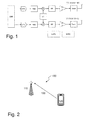
- the user equipment comprises a transmitter as shown in Figure 1 .
- the transmitter comprises two transmitter branches TX branch #1, TX branch #2.
- the Relative Phase Discontinuity (RPD) is defined as a difference of RP between two time instants t 1 and t 2 , i.e., ⁇ ( t 1 ) - ⁇ ( t 2 ) .
- the relative phase discontinuity is a measure of change of relative phase between different transmitter branches for any two adjacent timeslots.
- the relative phase discontinuity may degrade performance and/or increase loss in many scenarios.
- An object is to improve performance of a transmission from a user equipment to a radio base station.
- the object is achieved by a method, performed by a radio network node, for managing a transmission from a user equipment to the radio network node.
- the radio network node adapts a transport format relating to the transmission based on information indicating at least one mode switching point of a radio transmitter.
- the radio transmitter is comprised in the user equipment.
- a radio network node configured to manage a transmission from a user equipment to the radio network node.
- the radio network node comprises a processing circuit configured to adapt a transport format relating to the transmission based on information indicating at least one mode switching point of a radio transmitter.
- the radio transmitter is comprised in the user equipment.
- the object is achieved by a method, performed by a user equipment, for managing a transmission from the user equipment to a radio network node.
- the user equipment adapts the transmission based on information.
- the information indicates at least one mode switching point of a radio transmitter comprised in the user equipment.
- the object is achieved by a user equipment configured to manage a transmission from the user equipment to a radio network node.
- the user equipment comprises a processing circuit configured to adapt the transmission based on information.
- the information indicates at least one mode switching point of a radio transmitter comprised in the user equipment.
- the radio network node may select a more robust, or conservative, transport format.
- a more robust transport format will make it easier to decode, by the radio network node, the transmission than if a less robust transport format that would have been selected for the transmission as would be the case when the information indicating the at least one mode switching point is not accounted for.
- errors in decoding may decrease despite the existence of phase discontinuities.
- performance may increase. Thereby, an expected negative impact, due to the phase discontinuities, on the performance is reduced.
- a reduction of phase discontinuities and/or relative phase discontinuities, or the impact thereof, in the transmission from the user equipment to the radio base station is achieved.
- Another object may be how to make a radio network node aware of the information indicating at least one mode switching point of a radio transmitter, which is comprised in a user equipment.
- this object is achieved by a method performed by a radio network node for obtaining the information indicating the at least one mode switching point.
- the radio network node scans at least a portion of a transmit power range of a user equipment by increasing power of a reference signal and measuring the relative phase of the received reference signal.
- the radio network node detects a discontinuity in the measured relative phase, the radio network node registers the information indicating the at least one mode switching point as the transmit power at the detected discontinuity.
- the mode switching information is defined as the information about operation points at which the corresponding relative phase discontinuity or phase discontinuity changes abruptly. It may be related to the mode switching of radio transmitter components e.g. power amplifier (PA) or Radio Frequency Application Specific Integrated Circuit (RF ASIC).
- PA power amplifier
- RF ASIC Radio Frequency Application Specific Integrated Circuit
- the mode switching or aka the operation points depends upon the implementation of the radio components, e.g. PA.
- a user equipment may include a multi-stage PA, which comprises two or more PAs. Typically, only one of the PA is active at a time depending upon the user equipment transmit power level. This saves battery power of the user equipment and thus enhances battery life.
- a 3-stage PA has three PAs and 2 mode switching points.
- the mode switching information may therefore also include the number of PAs in a multi-stage PA.
- the mode switching information may include the transmit power levels of the operation points, or the transmit power difference between the consecutive operation points. It may also include the phase value of the operation points, or the phase differences between the consecutive operation points. It may further include the mode switching related parameters such as the hysteresis value. It may also comprise of the number of mode switching points over the total transmit power range of the user equipment, i.e. between the user equipment's maximum (23 dBm) and minimum (-50 dBm) output power levels.
- the mode switching information may also be defined over the user equipment transmit power range over which the user equipment radio transmitter requirements or certain types of radio transmitter requirements, e.g. transmit modulation quality defined between 23 dBm to -40 dBm. Due to the abrupt change in the phase of the signal at a mode switching point the accuracy with which the user equipment transmits power at the mode switching point generally becomes much worse.
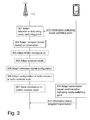
- FIG. 2 depicts an exemplifying radio communications system 100 in which embodiments herein may be implemented.
- the radio communications system 100 is a LTE system.
- the radio communication system may be any 3GPP cellular communication system, such as a Wideband Code Division Multiple Access (WCDMA) network, a Global System for Mobile communication (GSM network) or the like.
- WCDMA Wideband Code Division Multiple Access
- GSM Global System for Mobile communication
- the radio communication system 100 comprises a radio network node 110.
- radio network node may refer to an evolved Node B (eNB), a control node controlling one or more Remote Radio Units (RRUs), a radio base station, a base station, an access point or the like.
- eNB evolved Node B
- RRUs Remote Radio Units
- the radio communication system 100 comprises a user equipment 120.
- the user equipment 120 may send a transmission 130 to the radio network node 110.
- the term "user equipment” may refer to a mobile phone, a cellular phone, a Personal Digital Assistant (PDA) equipped with radio communication capabilities, a smartphone, a laptop or Personal Computer (PC) equipped with an internal or external mobile broadband modem, a tablet PC with radio communication capabilities, a portable electronic radio communication device, a sensor device equipped with radio communication capabilities or the like.
- the sensor may be any kind of weather sensor, such as wind, temperature, air pressure, humidity etc.
- the sensor may be a light sensor, an electronic switch, a microphone, a loudspeaker, a camera sensor etc.
- the user equipment 120 may comprise a radio transmitter, denoted 1420 in Figure 14 (not shown in Figure 2 ).
- the radio transmitter may comprise a first power amplifier and a second power amplifier.
- At least one mode switching point may indicate when, in terms of transmit power of the radio transmitter, the radio transmitter may switch from a first mode, in which the first power amplifier is operated, to a second mode, in which the second power amplifier is operated.
- the term "operated” may mean the power amplifier at hand is active, or used, for transmitting a transmission to be sent from the user equipment 120 to the radio network node 110.
- a purpose of using different power amplifiers for transmission at different transmit powers is to, for instance, improve linearity over the range of the power amplifier and to decrease power consumption.
- information indicating the at least one mode switching point of the radio transmitter may be useful both the radio network node 110 and the user equipment 120.
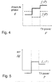
- Figure 3 illustrates an exemplifying method according to embodiments herein when implemented in the radio communication system 100 of Figure 2 .
- the illustrated method relates to management of the transmission 130 from the user equipment 120 to the radio network node 110.
- the transmission may be an uplink (UL) transmission.
- the radio network node 110 may obtain the information indicating at least one mode switching point in different manners as explained in the following.
- the obtained information may be determined by an indication received from the user equipment 120. See action 310 below.
- the obtained information may be pre-defined.
- the pre-defined information about different types, e.g. model and/or manufacturer, of the user equipment 120 may be stored in radio network node 110.
- the obtained information may be determined by measurements performed by the radio network node 110. See section "Obtaining information based on measurements”.
- the obtained information may be determined by a procedure for scanning, by the radio network node 110, transmit power range of the user equipment 120. See section "Obtaining information based on scanning UL transmit power range”.
- the radio network node may reduce Relative Phase Discontinuity (RPD) without knowledge about the indication that may be received from the user equipment.
- RPD Relative Phase Discontinuity
- the obtained information may relate to a first radio access technology, such as LTE or the like.
- the user equipment 120 is capable of at least the first radio access technology and a second radio access technology, such as High Speed Packet Access (HSPA).
- the method further comprises obtaining second information relating to the second radio access technology based on the information indicating at least one mode switching point for the first radio access technology provided that radio transmission characteristics for the first radio access technology is similar to radio transmission characteristics for the second radio access technology.
- the second information indicates at least one mode switching point of the radio transmitter 1420. See also section "Obtaining information based on common radio in multi-RAT UE".
- the radio network node 110 may combine any of the manners of how to obtain the obtained information disclosed above. A combination of two or more manners may be used to determine the obtained information more accurately.
- the radio network node 110 may first determine the information indicating at least one mode switching point, or "UE mode switching information", using the pre-defined information. Then, the radio network node 10 may further verify the UE mode switching information by using the method based on the measurements. If the results of the two methods match then the radio network node 110 may not perform any other method. However, if the results of the two methods don't match or only partially match then the radio network node 110 may perform yet another method e.g. based on scanning and so on.
- the radio network node 110 After the radio network node 110 has obtained the information relating to at least one mode switching point, the radio network node 110 adapts a Transport Format (TF) relating to the transmission based on the information indicating at least one mode switching point.
- TF Transport Format
- the radio network node 110 serving the user equipment 120 typically selects the TF of the transmission based on information such as signal quality, user bit rate requirements, service type etc. However, according to this embodiment the radio network node 110 also takes into account the information indicating the at least one mode switching point when adapting the TF of the transmission.
- the adaptation of UL transmission which is performed by the radio network node 110 serving the user equipment 120 may comprise the adaptation of the TF of the UL transmission which takes place on a suitable physical channel.
- an eNB as an example of the radio network node, can adapt the TF of the Physical Uplink Shared Channel (PUSCH) which carries data and/or data and control.
- PUSCH Physical Uplink Shared Channel
- the radio network node 110 determines that the user equipment 120 is causing significant RPD, i.e. higher than a threshold
- the radio network node 110 which in this example is an eNB, can select more conservative transport format than the TF recommended based on UL signal quality estimate. In this way the UL signal can be more easily decoded by the serving node.
- the radio network node 110 can determine the loss due to higher RPD by observing the UL receiver performance. In this way, it is possible to cope with potential loss of MIMO precoding gain due to higher RPD.
- the radio network node 110 uses the information indicating at least one mode switching point as basis when adapting different parameters relating to the transmission as explained in the following.
- the radio network node 110 may adapt a MIMO configuration of the user equipment 120 based on the information, wherein the MIMO configuration relates to the transmission.
- the radio network node 110 serving the user equipment 120 typically selects the MIMO configuration of the UL transmission based on information such as signal quality, user bit rate requirements, service type etc.
- the serving radio network node 110 also takes into account the information indicating the at least one mode switching point when adapting the MIMO configuration of the UL transmission.
- the radio network node 110 determines that the user equipment 120 is causing significant RPD, i.e. higher than a threshold, the radio network node 110 can select more conservative MIMO configuration, e.g., the number of spatial streams than the configuration recommended based on UL signal quality estimate. In this way the UL signal can be more easily recovered by the serving node, i.e. the radio network node 110.
- the radio network node 110 can determine the loss due to higher RPD by observing the UL receiver performance. In this way, it is possible to cope with potential loss of MIMO precoding gain due to higher RPD.
- the radio network node 110 may configure the user equipment 120 to a lower order multiple antenna transmission, e.g.
- the radio network node 110 may configure the UE with higher RPD from beamforming, e.g. 2x2 antenna scheme, to a switched antenna diversity. The latter does not cause RPD.
- the radio network node 110 may adapt an antenna mode of the user equipment 120 based on the information, which antenna mode relates to the transmission;
- the radio network node serving the user equipment 120 typically selects the UL antenna transmission mode for the UL transmission based on information such as UL signal quality, e.g. SINR, BLER etc, user bit rate requirements, service type etc.
- the radio network node 110 also takes into account the information indicating the at least one mode switching point when adapting the antenna transmission mode for the UL transmission.
- the radio network node 110 may adapt between the single antenna transmission and multiple antenna transmission modes depending upon the mode switching information. For example, if the radio network node 110 determines that the user equipment is causing significant RPD, i.e. higher than a threshold, then the radio network node 110 cannot exploit full MIMO gain. In this case the radio network node 110 may configure the user equipment 120 with higher RPD to single antenna transmission and release the relevant resource, i.e. multi antenna mode, to other UEs with smaller RPD.
- the relevant resource i.e. multi antenna mode
- the radio network node 110 may adapt a reference signal configuration relating to the transmission based on the information.
- the serving node such as the radio network node 110 may adapt one or more parameters related to a UL reference signal transmitted by the user equipment 120 in order to minimize the loss of UL signals due to RPD.
- UL reference signals are SRS in LTE, DMRS in LTE and sounding signals (aka sounding dedicated physical control channel (S-DPCCH)) in HSPA.
- the eNB may adapt the SRS configuration parameters, i.e. those parameters not related to the power control, such as the SRS periodicity. For example, if a certain user equipment such as e.g. the user equipment 120 experiences large RPD, the SRS-based precoding is not very useful i.e. it is not very accurate to select precoding parameter(s) based on UL received sgnal quality on SRS. Therefore, from system capacity point of view, it may be beneficial for the serving radio network node, such as the radio network node 110, to allocate more SRS resource to user equipments with smaller RPD such as e.g. the user equipment 120.
- the serving radio network node such as the radio network node 110
- the eNB can increase the SRS periodicity of the UEs with large RPD such that the user equipments with small RPD can be configured with smaller SRS periodicity. In this way the SRS resources can be utilized more efficiently and may also lower the UL interference in the cell.
- the radio network node 110 may adapt a configuration of a radio receiver 1230 comprised in the radio network node 110 based on the information indicating the at least one mode switching point.
- the radio receiver 1230 is illustrated in Figure 12 .
- the radio network node 110 serving the user equipment 120 may also adjust its receiver configuration ,e.g. parameters related to its receiver, for decoding the signals on UL transmission depending upon the UE mode switching information. For example if the user equipment's RPD or PD on any UL transmission is above a threshold then the radio network node 110 uses more robust receiver for decoding the signals transmitted by this user equipment 120. A more robust receiver is capable of decoding signals received with lower signal quality. For example the radio network node 110 may use more receive antennas for receiving the UL signals transmitted by the user equipment 120 whose mode switching information depicts that its RPD or PD is higher than a threshold.
- the radio network node 110 may use more receive antennas for receiving the UL signals transmitted by the user equipment 120 whose mode switching information depicts that its RPD or PD is higher than a threshold.
- the radio network node 110 may send the information to a further network node, which uses the information for transmission between the user equipment 120 and the further network node not shown in Figure 4 .
- Examples of the further network nodes are neighboring radio nodes, such as eNode B in LTE, Node B and Radio Network Controller (RNC) in HSPA etc), core network node, such as Mobility Management Entity (MME) in LTE) Minimization of drive test (MDT) node, Operation and Maintenance (O&M), Operational Support Systems (OSS), Self Organizing Network (SON) node, positioning node, e.g. E-SMLC in LTE etc.
- MME Mobility Management Entity
- MDT Mobility Management Entity
- O&M Operation and Maintenance
- OSS Operational Support Systems
- SON Self Organizing Network
- positioning node e.g. E-SMLC in LTE etc.
- eNode B may signal the information to another eNode B over X2 interface and to a positioning node using LPPa.
- the radio network node 110 may signal this information proactively or in response to explicit request received from another network node.
- the radio network node 110 may also signal this information to other nodes under specific scenario or condition e.g. at the time of cell change of the user equipment 120.
- the further network node receiving the above indicated information may use it for radio operation tasks and/or network management tasks.
- Specific examples of such tasks are using the information after cell change, e.g. Hand Over (HO), Primary Cell change etc, adjusting or configuration of network planning parameters, e.g. selection of antenna modes, receiver type in the network node etc.
- the new serving node does not have to again obtain the information relate to UE mode switching, adaptation of the UL transmission scheme etc.
- a positioning node may use the received information to select an appropriate positioning measurement for determining a location of the user equipment 120. For example if the UE mode switching leads to higher loss or degraded performance then it may select a positioning measurement which does not require the measuring node to perform positioning measurement on signals transmitted by the user equipment 120. For example positioning node may select a DL positioning measurement, e.g. Observed Time Difference of Arrival (OTDOA) Reference Signal Time Difference (RSTD), performed by the user equipment 120. This is because the higher RPD or PD on UL transmission may degrade the accuracy of the UL positioning measurements like UE Rx-Tx time difference, TA, base station (BS) Rx-Tx time difference etc. Similarly the positioning node may adapt or select a positioning measurement/positioning method based on UE mode switching characteristics.
- OTD Observed Time Difference of Arrival
- RSTD Reference Signal Time Difference
- the positioning node may adapt or select a positioning measurement/positioning method based on UE mode switching characteristics.
- the network node If the network node signals or forwards the information of performance, model, power class, supported bands, supported RATs etc. to other network nodes, it is possible to collect the mode switching information from the user equipments of the same type from other network nodes. This may help to improve the accuracy of the mode switching information.
- the user equipment 120 may send the information indicating at least one mode switching point to the radio network node 110.
- the radio network node 110 may obtain, i.e. receive, the information indicating the at least one mode switching point and use the information as explained in conjunction with e.g. action 302.
- the user equipment 120 may autonomously adapt the transmission based on the information indicating the at least one mode switching point.
- the user equipment 120 determines information indicating the at least one mode switching point, or the mode switching information related to its multi-stage radio implementation for the UL transmission, and autonomously adapts its UL transmission in order to avoid the UL transmitted signal causing higher RPD. This in turn will enable the serving radio network node 120 to more easily receive and decode the UL signal transmitted by the user equipment.
- the user equipment can apply any one or more of the UL adaptations disclosed above according to one or more pre-defined rules.
- the user equipment 120 is allowed to adapt certain PC parameters, e.g. within certain range, when certain condition related to mode switching is met e.g. when RPD or RP on any channel is above a threshold e.g. more than 40 degrees.
- the user equipment 120 is allowed to adapt between certain antenna transmission modes, e.g. between single and multiple antenna modes, when condition related to mode switching is met e.g. when RPD or RP on any channel is above a threshold e.g. more than 45 degrees.
- the user equipment 120 may be allowed to adapt between certain transport format of certain physical channel, e.g. for Physical Uplink Shared Channel (PUSCH) in LTE and E-DCH Dedicated Physical Data Channel (E-DPDCH) in HSPA, when condition related to mode switching is met e.g. when RPD or PD on any channel is above a threshold e.g. more than 50 degrees.
- PUSCH Physical Uplink Shared Channel
- E-DPDCH Dedicated Physical Data Channel
- the E-DPDCH is used when Enhanced Dedicated Channel (E-DCH) is configured.
- the threshold can typically be pre-defined. However the network node may also configure the threshold at the user equipment 120.
- the radio network node 110 may also explicitly configure the user equipment 120 whether the user equipment 120 is allowed to autonomously adapt the UL transmission or not. As an example, the radio network node 110 may explicitly configure the user equipment 120 according to one or more pre-defined rules.
- the adapting of the transmission may be performed by adapting a value relating to the transmission based on the information indicating at least one mode switching point.
- the value may comprise one or more of, as mentioned above:
- the adapting of the transmission may be performed when the information indicates that a relative phase discontinuity of transmission exceeds a threshold value.
- the user equipment 120 may send information relating to the adapted transmission to the radio network node 110.
- the radio network node 110 may be informed about how the user equipment 120 has autonomously adapted the transmission.
- the radio network node 110 may use the information relating to the adapted transmission when decoding the transmission from the user equipment 120.
- the user equipment 120 may also explicitly inform the radio network node 110, e.g. eNB in LTE and Node B and/or RNC in HSPA, that it has adapted an UL transmission due to mode switching.
- the user equipment 120 may also inform the network node regarding the details of the performed action(s) related to the adaptation of the UL transmission e.g. adaption of UL PC parameters, UL antenna modes etc.
- the user equipment 120 may also inform the network node of the reason of the adaption of the UL transmission e.g. due to RPD and/or PD is above a threshold.
- the user equipment 120 may report the above information for certain type of adaptation.
- the user equipment 120 may also log the above information and report the statistics to the network after certain time period e.g. to MDT node which may use it for network planning related tasks.
- the user equipment 120 may report this information proactively or in response to explicit request received from a network node.
- the network node uses the received information from the user equipment 120 to determine the statistics of the adaption of the UL transmissions by the user equipment 120 and also by several user equipments. The network node then adapts parameters related to the UL transmission in order to minimize unnecessary adaptation at the user equipment 120.
- the network node may also adapt a receiver type which is capable of handling signals, transmitted by the user equipment 120, which signals experience a higher RPD or PD.
- RAN Radio Access Network
- UEs wireless terminals
- RAN Radio Access Network
- HSDPA High-Speed Downlink Packet Access
- 3GPP 3 rd Generation Partnership Project
- the terms mobile terminal, wireless terminal, user equipment or UE can refer to any device that receives data from a communication network, and may include, but are not limited to, a mobile telephone ("cellular" telephone), laptop/portable computer, pocket computer, hand-held computer, and/or desktop computer, device-to-device communication capable devices.
- cellular mobile telephone
- laptop/portable computer laptop/portable computer
- pocket computer pocket computer
- hand-held computer hand-held computer
- desktop computer device-to-device communication capable devices.
- radio network node or “base station”, which may be referred to in various contexts as NodeB or eNodeB or eNB, for example, and "wireless terminal,” “mobile terminal,” or “wireless device”, often referred to as “UE” or “eUE” or “User Equipment”, should be considering non-limiting and does not necessarily imply a certain hierarchical relation between two particular nodes of a communication link.
- a base station e.g., a "NodeB”
- a wireless terminal e.g., a "UE”
- UE wireless terminal
- the RPD is defined as the difference of RP between two time instants t 1 and t 2 , i.e., ⁇ ( t 1 ) - ⁇ ( t 2 ) .
- the RPD of a transmitter branch typically comprises a power-dependent term and a time-dependent term.
- the power-dependent term depends on the transmit power, whereas the time-dependent term varies with time. From the viewpoint of modelling, the power-dependent term can be given as a function of the current transmit power, whereas the time-dependent term can be given as an additive random process.
- the power-dependent RPD mainly comes from the power/configuration mode switching by which each transmitter branch switches the gain/bias state.
- the potential sources of the power-dependent RPD can be summarized as follows.
- the RPD between the measurement and the relevant precoding is of interest.
- SRS is a natural choice for precoder selection
- the RPD may lead to non-optimal precoder selection, even when the wireless channel is perfectly known to the eNB. This may result in non-trivial performance loss, since the precoder selection typically relies on the phase information of the transmitter branches.
- the time frame of interest is about a few, or a few tens of, subframes. It depends on the processing time, due to for example measurement and precoder selection, and the SRS periodicity. For example, if the processing time is 8 msec and the period of SRS transmission is 10 msec, a minimum of 8 msec and a maximum of 17 msec should be assumed as the time frame. Given such a time frame, the power-dependent term has a larger impact on RPD than the time-dependent term and thus focus is on the power-dependent term, i.e., how to cope with it, in this disclosure.
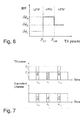
- the RP is given a function of the current transmit power.
- Figure 6 shows an example of the relationship between transmit power and RP. It is shown that RP changes abruptly across a few transmit power levels - referred to as switching points hereafter.
- the operation mode below P LM is called low-power mode (LPM)
- the operation mode between P LM and P MH is called mid-power mode (MPM)
- the operation mode above P MH is called high-power mode (HPM).
- LPM low-power mode
- MLM mid-power mode
- HPM high-power mode
- Each mode has its own bias state and the phase of a bias state is not necessarily equal to those of other bias states. This justifies the aforementioned RP change across the switching points.
- the transmit power change causes the mode switching of a transmitter, comprised in the user equipment 120, and the mode switching between SRS and PUSCH in turn causes the RPD.
- Figure 7 shows a typical case where PUSCH and SRS are transmitted with different power levels.
- the first SRS symbol, SRS 1 is transmitted at time instant t S,1 with power level Ps and the second SRS symbols, SRS 2 , is transmitted at time instant t S,2 with power level Ps.
- One of the PUSCH symbols, PUSCH is transmitted in between, i.e., at time instant t P with power level P P . Since the PUSCH power level is different from the SRS power level, RPD may occur between SRS and PUSCH.
- the two SRS symbols experience the same phase shift, since they are assumed to have the same power level. It is important to note that Ds and D P become different when Ps and P P are on different sides of a switching point, in other words, SRS 1 (or SRS 2 ) and PUSCH operate in different modes, as exemplified in Figure 8 . This causes RPD between SRS and PUSCH.
- precoder selection is generally affected by the phase information of the transmitter branches.
- the RPD between SRS and PUSCH may degrade the optimality of precoder selection significantly.
- the switching point information includes the power levels and the phase values of one or more switching points.
- the switching point information may be simply the PA type of the UE, e.g., switch mode PA or envelope tracking PA.
- the UE may need to measure the RP characteristic.
- the eNB obtains the switching point information from the UE, it selects the SRS or PUSCH transmit power so as to reduce the RPD.
- the SRS transmit power can be adjusted by changing the SRS power offset or the SRS bandwidth.
- the PUSCH transmit power can be adjusted by using TPC commands.
- the PD may also occur on an UL transmission, e.g. on UL physical channel etc.
- the embodiments are also applicable to PD in addition to RPD.
- UE may refer to the user equipment 120 when appropriate.
- This method is primarily performed in the radio network node 110 serving the user equipment 120.
- more than one radio network node 110 may also be involved in obtaining the mode switching information.
- LTE Long Term Evolution
- HSPA High Speed Packet Access
- Node B serving the user equipment 120
- RNC Radio Network Controller
- the term obtaining means that the network node may determine the UE mode switching information by one or more means.
- the radio network node 110 may obtain the mode switching information based on pre-defined information, stored in the equipment 120, which includes the switching point information declared by UE vendors in the specification. This may also be called as the vendor declaration or declared information.
- the vendor-specific switching point information may vary with the model and release of UE. The vendor-specific switching point information may also depend upon the frequency bands, RATs, number of supported RATs, power class of the UE for each RAT etc.
- the radio network node 110 e.g. eNode B, BS, Node B, RNC etc, can therefore store the declared information related to the switching point of the UE for different types, classes, models, release etc of UEs. This information can therefore be maintained in the radio network node 110 in the form of a look up table or a data base and it can be used for determining the switching point of a particular UE when it is served by the radio network node 110.
- the radio network node 110 identifies the UE type, class, release etc. After identifying the UE, the radio network node 110 checks the look up table (or database) containing the pre-defined switching point information related to the identified UE.
- the vendor and the model can be figured out by the radio network node 110 based on the International Mobile Subscriber Identity/ International Mobile Equipment Identity (IMSI/IMEI) of the UE.
- the network can also determine the release based on the Radio Resource Control (RRC) signaling.
- the UE reports its release, e.g. that it supports release 11, to the radio network node 110 during a setup or when requested by the network.
- additional UE information such as supported frequency bands, RATs, power class may be available to the eNB.
- the UE also informs the network about its supported bands, RATs, power class etc.
- the radio network node 110 may even implicitly determine the UE type based on historical data. For example the UEs with similar performance or behavior in the network can be grouped together and may be assumed to have the same mode switching points.
- the radio network node 110 can therefore map the pre-defined switching point information applicable to that of the identified UE.
- the radio network node 110 therefore eventually chooses the mode switching information of a specific UE from the predefined information.
- the determination of the switching point information may be performed in a RNC for each UE served by the RNC.
- the RNC may also maintain the pre-defined switching point information.
- the RNC after determining the switching point information for a UE informs the determined switching point information to the Node B serving that UE.
- the serving radio network node 110 can also measure the UL transmission, e.g., SRS, PUSCH, pilot signals etc, and associate it with the Power Headroom Report (PHR) from the UE to obtain the mode switching information.
- PHR or aka PH is the difference between the UE maximum power and the UE transmitted power expressed in dB scale.
- the eNB can measure the RP of the UE. For example, the consecutive SRS transmissions enable the eNB to measure the RP, when the fading channel remains static between the SRS transmissions.
- the PHR indicates that the SRS transmit power changes between the SRS transmissions, it is possible to find the power level and phase value of the switching point.
- the radio network node 110 may determine the mode switching information of a UE and use the same information for other similar UEs i.e. UEs of the same type in terms of performance, model, power class, supported bands, supported RATs etc. Therefore the switching point information can be determined by the radio network node 110 for certain number of UEs and can be stored in the node and used for the same and similar types of the UEs in the future e.g. for scheduling etc.
- the radio network node 110 collects the mode switching information from the UEs of the same type. This helps to improve the accuracy of the mode switching information. For example, when one UE has the SRS transmit power crossing one switching point and the other UE of the same type has the SRS transmit power crossing another switching point, it is possible to obtain the information on these two switching points for the UEs of the same type. In other words, by collecting the measurements from the UEs of the same type that operate in different modes, it is possible to obtain the complete mode switching information of UEs of the type. This may be useful when the SRS transmit power does not change so rapidly and it is practically impossible to obtain the complete mode switching information from the measurement of a single UE.
- the radio network node 110 may obtain the mode switching information by scanning the transmit power range of interest and measure the corresponding RP. For example, the eNB ramps up the SRS transmit power monotonically and measures the corresponding RP. If the SRS transmit power ranges from the minimum transmit power to the maximum transmit power, it is possible to capture the complete switching point information. Alternatively, the eNB may ramp down the SRS transmit power monotonically and measures the corresponding RP i.e. from maximum to minimum UE transmit power. The radio network node 110 may apply this procedure when there is low uplink traffic in the cell and/or when UE is not transmitting any data. In this way the network can more accurately determine the mode switching information by assigning adequate resources.
- the SRS transmit power is determined by parameters such as the SRS bandwidth and the desired target SNR value etc. For example, by changing the SRS bandwidth, it is possible to fulfill the power ramp up/down. Note that such power ramp up/down can be fulfilled on a per subframe basis, if aperiodic SRS is used.
- the power step of the aforementioned power ramp up/down determines the amount of the SRS resource.
- the radio network node 110 can select the power step based on the declared information. For example, if the radio network node 110 can figure out the approximated power level difference between two switching points, it can adjust the power step accordingly.
- the radio network node 110 may determine the mode switching information of a UE by scanning and use the same information for other similar UEs i.e. UEs of the same type in terms of performance, model, power class, supported bands, supported RATs etc. Therefore the switching point information can be determined by the radio network node 110 for certain number of UEs based on scanning and can be stored in the node and used for the same and similar types of the UEs in future e.g. for scheduling etc.
- the radio network node 110 collects the mode switching information from the UEs of the same type. This helps to improve the accuracy of the mode switching information. For example, when the radio network node 110 scans the first half of the transmit power range for one UE and scans the second half of the transmit power range for another UE of the same type, it is possible to obtain the information on these transmit power ranges for the UEs of the same type. In other words, by collecting the power ramp up/down from the UEs of the same type that operate in different modes, it is possible to obtain the complete mode switching information of UEs of the type. This may be useful when the SRS resource dedicated to each UE is not enough to scan the whole transmit power range and it is practically impossible to obtain the complete mode switching information from the power ramp up/down of a single UE.
- the radio network node 110 may want to scan the transmit power range for each UE, even when the mode switching information is available from other UEs of the same type.
- the mode switching information obtained from other UEs of the same type can be used as initial information, for example, to optimize the power step for the power ramp up/down of a UE of the same type.
- the radio network node 110 obtains the mode switching information based on explicit indication from the UE.
- the mode switching information can be acquired by the radio network node 110 from the UE which may contain the pre-determined information stored in the UE, Alternatively when the radio network node 110 requests the mode switching information or when the UE has to send the mode switching information to the radio network node 110 then the UE performs certain radio measurement to first obtain the mode switching information.
- the UE may perform measurements such as UL transmit power to determine the mode switching information.
- Such a network-triggered UE measurement and report may help reduce UE power consumption, for example, when the radio network node 110 can obtain the mode switching information from the UEs of the same type and wants to reuse the information for other UEs of the same type.
- the UE may signal the mode switching information which may be specific for different RATs, bands, UE power class etc. For example if UE supports LTE and HSPA, then it may report mode switching information for each RAT. Alternatively it may report one common mode switching information for all RATs.
- the UE may send the mode switching information to the radio network node 110 in any of the following manner:
- the UE may report its mode switching information during one or more of the following occasions:
- the radio network node 110 receiving the mode switching information from a UE may store the received information and may use this also for similar UEs which don't signal their own mode switching information.
- the term similar UE implies the UEs of the same type in terms of performance, model, power class, supported bands, supported RATs etc.
- the similarity between UEs can be determined using the mechanism described earlier, for example by the method of obtaining information through pre-defined information.
- the similar UE types are expected to have the same mode switching capability. This approach also reduces the signaling overheads since all UEs don't have to signal their mode switching information to the radio network node 110.
- the radio network node 110 may obtain the mode switching information of a UE for certain RAT, e.g. LTE, using any of the methods disclosed above. Let us call this RAT as reference RAT. The radio network node 110 then observes the radio transmitter performance of that UE when it operates on another RAT. Example of radio transmitter performance is accuracy or tolerance of the UE maximum output power. If the performance on the two RATs are the same or similar then the network may assume that the same mode switching information is applicable on both RATs. For example only LTE part of the multi-RAT (HSPA/LTE) UE may explicitly indicate its mode switching information to the radio network node 110. However the HSPA and LTE may use a common radio and therefore mode switching information may be the same for both RATs.
- LTE part of the multi-RAT (HSPA/LTE) UE may explicitly indicate its mode switching information to the radio network node 110. However the HSPA and LTE may use a common radio and therefore mode switching information may be the same for both RATs.
- the radio network node 110 upon determining the UE mode switching information adapts the UL transmission of the UE to improve the UL performance e.g. improving UL reception quality at the radio network node 110, UL detection performance at the radio network node 110 etc.
- all UEs may not have multi-stage PA, e.g., envelope tracking PA, and therefore there is no mode switching for this UE when UE transmits signals in the uplink.
- the radio network node 110 therefore adapts the UL transmission only of those UEs which does mode switching and whose mode switching information is available.
- the radio network node 110 may apply one or combinations of these adaptations.
- the serving radio network node serving the UE typically selects the UL PC parameters for this UE based on UL received signal quality. However according to this embodiment the radio network node 110 also takes into account the mode switching information of the UE when selecting the UL PC parameters.
- the adaptation of UL transmission includes the adaptation of the power control related parameters configured by the radio network node 110, e.g. the TPC commands, the resource allocation, such as the SRS or PUSCH bandwidth, the SRS power offset etc.
- the parameter related to resource allocation can be UL grant or aka UL scheduling grant or UL assigned resource etc.
- the parameters related to SRS configuration can be adapted on a per subframe basis, if aperiodic SRS is configured with different parameters.
- These UL PC parameters which can be adapted are signaled to the UE and can be updated by the network serving the UE. For example, given the power levels of the switching points, it is possible for the network to adjust one or more parameters related to the UL PC. This in turn can enable the UE to adapt the SRS or PUSCH transmit power such that there is no mode switching between SRS and PUSCH. Obviously, this may help to reduce the RPD. In addition, given the phase values of the switching points, further optimization of RPD is possible. Note that any parameters used as the input argument of the power control formula can be involved in the adaptation of the UL transmission.
- the UE determines the mode switching information related to its multi-stage radio implementation for the UL transmission and autonomously adapts its UL transmission in order to avoid the UL transmitted signal causing higher RPD. This in turn will enable the serving node to more easily receive and decode the UL signal transmitted by the UE.
- the UE can apply any one or more of the UL adaptations disclosed above according to one or more pre-defined rules.
- the radio network node 110 signals or forwards to other network nodes any information, parameters, results or statistics related to the:
- the information forwarded to other nodes may include any information obtained by the radio network node according to e.g. action 301.
- the several functional blocks of figure 3 may be implemented using digital logic and/or one or more microcontrollers, microprocessors, or other digital hardware.
- several or all of the various functions of receiver circuits in figure 3 may be implemented together, such as in a single application-specific integrated circuit (ASIC), or in two or more separate devices with appropriate hardware and/or software interfaces between them.
- ASIC application-specific integrated circuit
- Several of the functional blocks of receiver circuits in figure 3 may be implemented on a processor shared with other functional components of a wireless terminal.
- processors or “controller” as used herein does not exclusively refer to hardware capable of executing software and may implicitly include, without limitation, digital signal processor (DSP) hardware, read-only memory (ROM) for storing software, random-access memory for storing software and/or program or application data, and non-volatile memory.
- DSP digital signal processor
- ROM read-only memory
- RAM random-access memory
- non-volatile memory non-volatile memory
- the position of the target device is determined by using one or more positioning measurements, which can be performed by a suitable measuring node or device.
- the measuring node can either be the target device itself, a separate radio node (i.e. a standalone node), serving and/or neighboring node of the target device etc.
- the measurements can be performed by one or more types of measuring nodes.
- Some exemplary positioning methods are:
- the positioning node In LTE the positioning node, aka Evolved Serving Mobile Location Center (E-SMLC) or location server, configures the UE, eNode B or LMU to perform one or more positioning measurements depending upon the positioning method. The positioning measurements are used by the UE or by a measuring node or by the positioning node to determine the UE location.
- the positioning node communicates with UE using LTE Positioning Protocol (LPP) protocol and with eNode B using LTE Positioning Protocol A (LPPa) protocol.
- LTP LTE Positioning Protocol
- LPPa LTE Positioning Protocol A
- WCDMA Wideband Code Division Multiple Access
- HSPA High Speed Packet Access
- UTRA Universal Terrestrial Radio Access
- FDD Frequency Division Duplex
- TDD Time Division Duplex
- UMB Ultra Mobile Broadband
- GSM Global System for Mobile Communication
- EDGE GSM Enhanced Data Rates for GSM Evolution
- GERAN Wireless Local Area Network
- WLAN Wireless Local Area Network
- eNB evolved Node B
- UE User Equipment
- the embodiments herein are applicable to any type of radio network node e.g. base station, eNode B, multi-standard radio (MSR) radio node, Node B, access point relay, donor node serving or controlling a relay etc.
- radio network node e.g. base station, eNode B, multi-standard radio (MSR) radio node, Node B, access point relay, donor node serving or controlling a relay etc.
- MSR multi-standard radio
- transmit diversity can be regarded as a special case of the multiple input multiple output (MIMO) transmission scheme, which can also be used in the uplink.
- MIMO multiple input multiple output
- the embodiments herein also apply to multi-point carrier aggregation systems i.e. are applicable to each CC in CA or in CA combination with CoMP etc.
- the embodiments are applicable to transmission on each CC in CA and/or CoMP.
- MIMO is a key element of an air interface for high-speed wireless communications for many wireless communication technologies such as Long Term Evolution (LTE) and High Speed Packet Access (HSPA). MIMO can use the diversity in the channel to provide multiplexing gain by enabling the simultaneous transmission of multiple streams known as layers. In LTE and HSPA, MIMO is used both in downlink (DL) and uplink (UL) aka DL MIMO and UL MIMO respectively.
- LTE Long Term Evolution
- HSPA High Speed Packet Access
- R Denoting the number of transmit antennas, receive antennas, and layers by NT, NR, and R, respectively, R is never greater than NT (and, often, smaller or equal to NR).
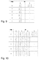
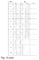
- MIMO uses a precoder, often expressed mathematically as a left-multiplication of a layer signal vector (R x 1) by a precoding matrix (NT x R), which is chosen from a pre-defined set of matrices, a so-called codebook exemplified in Figure 9 and Figure 10 .
- Each precoding matrix is indexed by rank indicator (RI) and precoding matrix indicator (PMI).
- the precoding matrix usually consists of linearly-independent columns, and thus R is referred to as the rank of codebook.
- R is referred to as the rank of codebook.
- One purpose of this kind of precoder is to match the precoding matrix with the Channel State Information (CSI) so as to increase the received signal power and also to some extent reduce inter-layer interference, thereby improving the Signal-to-Interference-plus-Noise-Ratio (SINR) of each layer.
- CSI Channel State Information
- the CSI is measured or estimated by the UE on DL radio signals (e.g. reference signals) and reporting to the serving radio node.
- the CSI is measured or estimated by the serving radio node on UL signals (e.g. reference signal) transmitted by the UE.
- UL CSI are UL SINR etc.
- Examples of DL CSI in LTE are CQI, RI and PMI.
- Examples of DL CSI in HSPA are CQI and pre-coding indicator (PCI). Consequently, the precoder selection requires the transmitter to know the channel properties and, generally speaking, the more accurate the CSI, the better the precoder matches.
- precoder selection is made by the receiver, such as an eNB, so that there is no need for feeding channel information back to the transmitter.
- precoder selection includes not only rank selection but precoding matrix selection throughout this disclosure. Instead, it is necessary for the receiver to obtain channel information, which can usually be facilitated by transmitting a known signal, in the case of LTE UL, the Demodulation Reference Signal (DM-RS) and the Sounding Reference Signal (SRS). Both DM-RS and SRS are defined in frequency domain and derived from Zadoff-Chu sequence.
- DM-RS Demodulation Reference Signal
- SRS Sounding Reference Signal
- the precoder selection is preferably based on SRS, since it is possible to obtain the physical channel through SRS.
- the uplink transmit diversity is also a special type of UL multi antenna transmission. It is specified for LTE and being specified for HSPA in release 11.
- the baseline and typical UE implementation comprises of a single uplink transmit antenna used for all types of uplink transmission.
- high end UEs may have and use multiple uplink transmit antennas for uplink transmission. This is commonly referred to as uplink transmit diversity.
- the objective of the transmit diversity transmission is to achieve higher uplink data rate and lower UE transmission power by the virtue of spatial, angular and temporal diversities.
- the most common uplink transmit diversity consists of two uplink transmit antennas.
- the signals from two or more uplink transmit diversity antennas may be transmitted in different manner in terms of their phases, amplitude, power etc. This gives rise to different uplink transmit diversity schemes.
- Some exemplary schemes are:
- multi-carrier or carrier aggregation may be used.
- multiple 20 MHz carriers or even smaller carriers e.g. 5 MHz
- Each carrier in multi-carrier or carrier aggregation system is generally termed as a Component Carrier (CC) or sometimes is also referred to a cell.
- CC Component Carrier
- CA Carrier Aggregation
- multi-carrier system multi-cell operation
- multi-carrier operation multi-carrier
- CA transmission and/or reception.
- the CA is used for transmission of signaling and data in the uplink and downlink directions.
- One of the CCs is the primary component carrier (PCC) or primary carrier or anchor carrier.
- the remaining ones are called secondary component carrier (SCC) or secondary carriers or supplementary carriers.
- the primary or anchor CC carries the essential UE specific signaling.
- the primary CC exists in both uplink and direction CA.
- the network may assign different primary carriers to different UEs operating in the same sector or cell.
- the UE has more than one serving cell in downlink and/or in the uplink: one primary serving cell and one or more secondary serving cells operating on the PCC and SCC respectively.
- the serving cell is interchangeably called as primary cell (PCell) or primary serving cell (PSC).
- the secondary serving cell is interchangeably called as secondary cell (SCell) or secondary serving cell (SSC).
- the PCell and SCell(s) enable the UE to receive and/or transmit data. More specifically the PCell and SCell exist in DL and UL for the reception and transmission of data by the UE.
- the remaining non-serving cells on the PCC and SCC are called neighbor cells.
- the CCs belonging to the CA may belong to the same frequency band (aka intra-band CA) or to different frequency band (inter-band CA) or any combination thereof (e.g. 2 CCs in band A and 1 CC in band B).
- the inter-band CA comprising of carriers distributed over two bands is also called as dual-band-dual-carrier-HSDPA (DB-DC-HSDPA) in HSPA or inter-band CA in LTE.
- DB-DC-HSDPA dual-band-dual-carrier-HSDPA
- the CCs in intra-band CA may be adjacent or non-adjacent in frequency domain (aka intra-band non-adjacent CA).
- a hybrid CA comprising of intra-band adjacent, intra-band non-adjacent and inter-band is also possible.
- multi-RAT carrier aggregation or “multi-RAT-multi-carrier system” or simply “inter-RAT carrier aggregation”, where RAT is short for Radio Access Technology.
- the carriers from WCDMA and LTE may be aggregated.
- Another example is the aggregation of LTE and Code Division Multiple Access 2000 (CDMA2000) carriers.
- CDMA2000 Code Division Multiple Access 2000
- the carrier aggregation within the same technology as described can be regarded as 'intra-RAT' or simply 'single RAT' carrier aggregation.
- the multi-carrier operation may also be used in conjunction with multi-antenna transmission.
- signals on each CC may be transmitted by the eNB to the UE over two or more antennas.
- the CCs in CA may or may not be co-located in the same site or base station or radio network node (e.g. relay, mobile relay etc). For instance the CCs may originate (i.e. transmitted / received) at different locations (e.g. from non-located BS or from BS and RRH or RRU). Examples of combined CA and multi-point communication are Distributed Antenna System (DAS), RRH, RRU, Coordinated Multiple Point Transmission and Reception (CoMP), multi-point transmission / reception etc.
- DAS Distributed Antenna System
- RRH Remote Radio Access
- RRU Coordinated Multiple Point Transmission and Reception
- CoMP Coordinated Multiple Point Transmission and Reception
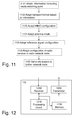
- Figure 11 shows a flowchart of an exemplifying method, performed by the radio network node 110, for managing the transmission from the user equipment 120 to the radio network node 110.
- the following actions may be performed in any suitable order.
- the radio network node 110 may obtain the information indicating at least one mode switching point based on one or more of:
- the obtained information may relate to a first radio access technology, wherein the user equipment 120 is capable of at least the first radio access technology and a second radio access technology, wherein the method further comprises obtaining second information relating to the second radio access technology based on the information indicating at least one mode switching point for the first radio access technology provided that radio transmission characteristics for the first radio access technology is similar to radio transmission characteristics for the second radio access technology, wherein the second information indicates at least one mode switching point of the radio transmitter 1420.
- This action is similar to action 301.
- the radio network node 110 adapts a transport format relating to the transmission based on information indicating at least one mode switching point of a radio transmitter 1420.
- the radio transmitter 1420 is comprised in the user equipment 120.
- the radio transmitter 1420 may comprise a first power amplifier 421 and a second power amplifier 422.
- the at least one mode switching point may indicate when, in terms of transmit power of the radio transmitter 1420, the radio transmitter 1420 switches from a first mode, in which the first power amplifier is operated , to a second mode, in which the second power amplifier is operated.
- This action is similar to action 302.
- the radio network node 110 may perform one or more of:
- This action is similar to one or more of actions 303, 304, 305 and 306.
- the radio network node 110 may send the information to a further network node, which uses the information for transmission between the user equipment 120 and the further network node. This action is similar to action 307.
- Figure 12 shows an exemplifying radio network node 110 which is configured to manage the transmission from the user equipment 120 to the radio network node 110.
- the radio network node 110 comprises a processing circuit 1210 configured to adapt a transport format relating to the transmission based on information indicating at least one mode switching point of the radio transmitter 1420.
- the radio transmitter 1420 is comprised in the user equipment 120.
- the processing circuit 1210 may further be configured to obtain the information indicating the at least one mode switching point of the radio transmitter 1420 based on one or more of:
- the obtained information relates to a first radio access technology, wherein the user equipment 120 is capable of at least the first radio access technology and a second radio access technology, wherein the processing circuit 1210 further is configured to obtain second information relating to the second radio access technology based on the information for the first radio access technology provided that radio transmission characteristics for the first radio access technology is similar to radio transmission characteristics for the second radio access technology, wherein the second information indicates at least one mode switching point of the radio transmitter 1420.
- the processing circuit 1210 may further be configured to one or more of:
- the processing circuit 1210 may further be configured to send the information to a further network node, which is capable of using the information for transmission between the user equipment 120 and the further network node.
- the radio network node 110 further comprises a transmitter 1220, which may be configured to send one or more of the information indicating the at least one mode switching point, explicit configuration information and/or other numbers, values or parameters described herein.
- the radio network node 110 further comprises a receiver 1230, which may be configured to receive one or more of the information indicating the at least one mode switching point, the information relating the transmission adapted by the user equipment and/or other numbers, values or parameters described herein.
- the radio network node 110 further comprises a memory 1240 for storing software to be executed by, for example, the processing circuit.
- the software may comprise instructions to enable the processing circuit to perform the method in the radio network node 110 as described above in conjunction with Figure 3 and/or 11.
- Figure 13 shows a flowchart of an exemplifying method, performed by the user equipment 120, for managing a transmission from the user equipment 120 to the radio network node 110.
- the following actions may be performed in any suitable order.
- the user equipment 120 may send the information indicating at least one mode switching point to the radio network node 110. This action is similar to action 310.
- the user equipment 120 adapts the transmission based on information, wherein the information indicates at least one mode switching point of a radio transmitter 1420 comprised in the user equipment 120. This action is similar to action 311.
- the adapting of the transmission may further comprise adapting a value relating to the transmission based on the information, wherein the value comprises one or more of:
- the adapting of the transmission may be performed when the information indicates that a relative phase discontinuity of transmission exceeds a threshold value.
- the adapting of the transmission may be performed provided the user equipment 120 is explicitly configured, by the radio network node 110, to be allowed to perform the adapting 311 of the transmission.
- the user equipment 120 may send information relating to the adapted transmission to the radio network node 110. This action is similar to action 312.
- Figure 14 shows an exemplifying user equipment 120 which is configured to manage the transmission from the user equipment 120 to the radio network node 110.
- the user equipment 120 comprises a processing circuit 1410 configured to adapt the transmission based on information.
- the information indicates at least one mode switching point of a radio transmitter 1420 comprised in the user equipment 120.
- the processing circuit 1410 may further be configured to adapt a value relating to the transmission based on the information.
- the value comprises one or more of:
- the processing circuit 1410 may further be configured to send information relating to the adapted transmission to the radio network node 110.
- the processing circuit 1410 may further be configured to send the information indicating at least one mode switching point to the radio network node 110.
- the processing circuit 1410 may further be configured to adapt the uplink transmission when the information indicates that a relative phase discontinuity of uplink transmission exceeds a threshold value for indicating relative phase discontinuity.
- the processing circuit 1410 may further be configured to adapt the uplink transmission provided the user equipment 120 is explicitly configured, by the radio network node 110, to be allowed to adapt the uplink transmission.
- the user equipment 120 further comprises a transmitter 1420, which may be configured to send one or more of the information indicating the at least one mode switching point, the information relating the transmission adapted by the user equipment and/or other numbers, values or parameters described herein.
- the user equipment 120 further comprises a receiver 1430, which may be configured to receive one or more of the explicit information for allowing autonomous adaption of the transmission information indicating the at least one mode switching point and/or other numbers, values or parameters described herein.
- the user equipment 120 further comprises a memory 1440 for storing software to be executed by, for example, the processing circuit.
- the software may comprise instructions to enable the processing circuit to perform the method in the user equipment 120 as described above in conjunction with Figure 3 and/or 13.
- processing circuit may refer to a processing unit, a processor, an application specific integrated circuit (ASIC), a field-programmable gate array (FPGA) or the like.
- ASIC application specific integrated circuit
- FPGA field-programmable gate array
- a processor, an ASIC, an FPGA or the like may comprise one or more processor kernels.
- memory may refer to a hard disk, a magnetic storage medium, a portable computer diskette or disc, flash memory, random access memory (RAM) or the like. Furthermore, “memory” may refer to an internal register memory of a processor.
- the present disclosure comprises methods and apparatuses for determining the mode switching information of a radio transmitter and adapting the transmission to improve the reception performance.
- the transmitter is located in a user equipment, and the signals transmitted are received in a base station, such as an eNodeB.
- a method in a radio network node serving a UE comprises the steps of:
- a radio network node provided with circuitry to obtain the UE radio transmitter mode switching information and adapt the UL transmission.
- the radio network node may obtain the radio transmitter mode switching information based on one or more of the following means:
- adapting the UL transmission related to the UE to improve UL reception quality may comprise one or more of:
- a method in a radio network node further comprises the steps of:
- a method in a UE served by a radio network node comprises the steps of:
- the present invention includes the subject-matter as defined in the following numbered paragraphs (abbreviated "para.”).
Landscapes
- Engineering & Computer Science (AREA)
- Computer Networks & Wireless Communication (AREA)
- Signal Processing (AREA)
- Mobile Radio Communication Systems (AREA)
- Radio Transmission System (AREA)
Applications Claiming Priority (2)
| Application Number | Priority Date | Filing Date | Title |
|---|---|---|---|
| US201261708252P | 2012-10-01 | 2012-10-01 | |
| EP13727354.6A EP2904715B1 (de) | 2012-10-01 | 2013-04-09 | Funkknoten, benutzervorrichtung und verfahren zur verwaltung einer übertragung |
Related Parent Applications (1)
| Application Number | Title | Priority Date | Filing Date |
|---|---|---|---|
| EP13727354.6A Division EP2904715B1 (de) | 2012-10-01 | 2013-04-09 | Funkknoten, benutzervorrichtung und verfahren zur verwaltung einer übertragung |
Publications (2)
| Publication Number | Publication Date |
|---|---|
| EP3139510A1 true EP3139510A1 (de) | 2017-03-08 |
| EP3139510B1 EP3139510B1 (de) | 2018-06-20 |
Family
ID=48577161
Family Applications (2)
| Application Number | Title | Priority Date | Filing Date |
|---|---|---|---|
| EP16194396.4A Active EP3139510B1 (de) | 2012-10-01 | 2013-04-09 | Funkknoten, benutzervorrichtung und verfahren zur verwaltung einer übertragung |
| EP13727354.6A Active EP2904715B1 (de) | 2012-10-01 | 2013-04-09 | Funkknoten, benutzervorrichtung und verfahren zur verwaltung einer übertragung |
Family Applications After (1)
| Application Number | Title | Priority Date | Filing Date |
|---|---|---|---|
| EP13727354.6A Active EP2904715B1 (de) | 2012-10-01 | 2013-04-09 | Funkknoten, benutzervorrichtung und verfahren zur verwaltung einer übertragung |
Country Status (12)
| Country | Link |
|---|---|
| US (2) | US9497798B2 (de) |
| EP (2) | EP3139510B1 (de) |
| JP (1) | JP5905998B2 (de) |
| KR (1) | KR101649535B1 (de) |
| CN (1) | CN104904132B (de) |
| AU (1) | AU2013326227B2 (de) |
| CA (1) | CA2886761C (de) |
| IL (1) | IL237999B (de) |
| IN (1) | IN2015DN02085A (de) |
| NZ (1) | NZ706066A (de) |
| TW (1) | TWI608755B (de) |
| WO (1) | WO2014053921A1 (de) |
Cited By (1)
| Publication number | Priority date | Publication date | Assignee | Title |
|---|---|---|---|---|
| CN111787629A (zh) * | 2019-04-03 | 2020-10-16 | 大唐移动通信设备有限公司 | 一种模式切换后的多用户配对处理方法及装置 |
Families Citing this family (39)
| Publication number | Priority date | Publication date | Assignee | Title |
|---|---|---|---|---|
| US8909283B2 (en) * | 2011-10-11 | 2014-12-09 | Telefonaktiebolaget L M Ericsson (Publ) | Transmit power adjustment to reduce a relative phase discontinuity |
| KR102050928B1 (ko) * | 2012-10-16 | 2019-12-03 | 삼성전자주식회사 | 이동통신 시스템에서 사용자 단말 선택 방법 및 장치 |
| WO2014106336A1 (en) * | 2013-01-06 | 2014-07-10 | Telefonaktiebolaget L M Ericsson (Publ) | Method and apparatus for adaptive resource allocation |
| EP2944134B1 (de) * | 2013-01-14 | 2019-12-04 | Telefonaktiebolaget LM Ericsson (publ) | Handhabung von uplink-sendeleistungsmeldungen |
| CN103118389B (zh) * | 2013-01-25 | 2015-11-18 | 大唐移动通信设备有限公司 | 一种射频拉远模块的温度检测方法和装置 |
| US9337982B2 (en) * | 2013-04-05 | 2016-05-10 | Qualcomm Incorporated | Adaptive antenna management in LTE |
| US9603098B2 (en) | 2013-05-02 | 2017-03-21 | Samsung Electronics Co., Ltd. | Method and apparatus for controlling uplink power in wireless communication system |
| US9736801B1 (en) | 2013-05-20 | 2017-08-15 | Marvell International Ltd. | Methods and apparatus for synchronizing devices in a wireless data communication system |
| US9521635B1 (en) * | 2013-05-21 | 2016-12-13 | Marvell International Ltd. | Methods and apparatus for selecting a device to perform shared functionality in a deterministic and fair manner in a wireless data communication system |
| CN104254144B (zh) * | 2013-06-27 | 2019-07-16 | 中兴通讯股份有限公司 | 模式切换方法及装置 |
| US9521520B2 (en) * | 2013-11-13 | 2016-12-13 | Cisco Technology, Inc. | Distributed-input OFDM angle-of-arrival scheme for location determination |
| TWI533515B (zh) * | 2013-12-31 | 2016-05-11 | 瑞昱半導體股份有限公司 | 天線分集機制與波束成型機制的共存控制方法與機器可讀媒體 |
| US9883472B1 (en) | 2014-04-30 | 2018-01-30 | Marvell International Ltd. | Methods and apparatus for beaconing within a wireless network based on an indication of distance |
| CN105337893B (zh) | 2014-05-30 | 2020-12-01 | 索尼公司 | 电子设备、中心节点和网络侧设备、传输方法和配置方法 |
| CN105450272B (zh) * | 2014-09-15 | 2021-07-20 | 中兴通讯股份有限公司 | 一种导频信息的反馈方法、装置及终端 |
| US9756544B2 (en) * | 2014-10-31 | 2017-09-05 | Amazon Technologies, Inc. | Reconfigurable antenna system |
| EP3241284B1 (de) * | 2014-12-30 | 2020-06-24 | Sony Corporation | Bestimmung von diversitätsmodi für mimo-systeme |
| CN104753578B (zh) * | 2015-03-16 | 2018-02-02 | 大唐移动通信设备有限公司 | 一种确定辅载波的波束赋形gob向量的方法和设备 |
| DE102015110160B4 (de) | 2015-06-24 | 2018-03-29 | Intel IP Corporation | Mehrfachsendefähiges Datensendesystem und Verfahren zu dessen Betreiben |
| EP3941138A1 (de) | 2015-07-28 | 2022-01-19 | Panasonic Intellectual Property Corporation of America | Endgerät, basisstation, sendeverfahren und empfangsverfahren |
| US10231179B2 (en) * | 2015-08-06 | 2019-03-12 | Qualcomm Incorporated | Access point standby power optimization across an arbitrary number of associated clients |
| CN106455070B (zh) * | 2015-08-12 | 2022-03-15 | 中兴通讯股份有限公司 | 一种控制面下行信令的传输方法及系统 |
| US10715226B2 (en) * | 2016-02-12 | 2020-07-14 | Nokia Solutions And Networks Oy | Apparatus and method for control signalling in uplink precoding |
| ES2909588T3 (es) | 2016-05-12 | 2022-05-09 | Nokia Technologies Oy | Técnicas para notificar la capacidad de conmutación de SRS de un equipo de usuario |
| WO2017198308A1 (en) * | 2016-05-20 | 2017-11-23 | Nokia Solutions And Networks Oy | Power efficiency in multiple radio access technologies scenarios |
| KR102505590B1 (ko) * | 2016-09-30 | 2023-03-03 | 엘에스전선 주식회사 | 복합 결합기 및 그를 이용한 누설동축케이블 무선통신시스템 |
| US10469224B2 (en) * | 2016-09-30 | 2019-11-05 | Qualcomm Incorporated | Joint transmission of precoded and unprecoded sounding reference signals in uplink |
| CN107959546B (zh) * | 2016-10-18 | 2020-06-16 | 华为技术有限公司 | 一种窄带系统空口资源的自适应配置调整方法及装置 |
| EP3540990B1 (de) | 2016-11-29 | 2022-03-16 | Huawei Technologies Co., Ltd. | Verfahren und vorrichtung zur verarbeitung einer digitalen vorverzerrung |
| WO2018127764A1 (en) * | 2017-01-06 | 2018-07-12 | Telefonaktiebolaget Lm Ericsson (Publ) | Explicit configuration of paging and control channel in system information |
| US11147108B2 (en) * | 2017-12-20 | 2021-10-12 | Telefonaktiebolaget Lm Ericsson (Publ) | Method for performing continuous deployment and feedback from a radio network node |
| US10715229B2 (en) | 2018-01-19 | 2020-07-14 | At&T Intellectual Property I, L.P. | Facilitating semi-open loop based transmission diversity for uplink transmissions for 5G or other next generation networks |
| US11832120B2 (en) | 2018-03-26 | 2023-11-28 | Beijing Xiaomi Mobile Software Co., Ltd. | Information recording method and information recording apparatus |
| US11438846B2 (en) * | 2018-08-20 | 2022-09-06 | Qualcomm Incorporated | Solutions to handle mis-alignment between radio access technologies (RATs) in dual connectivity (DC) |
| US10701694B2 (en) * | 2018-08-21 | 2020-06-30 | Phazr, Inc. | Selective crest factor reduction and digital pre-distortion of physical channels and physical signals |
| US10826595B2 (en) * | 2018-12-06 | 2020-11-03 | Aero5G, Inc. | GNSS-assisted wireless communication |
| US11317305B2 (en) * | 2019-09-03 | 2022-04-26 | Silvus Technologies, Inc. | User interface for MIMO networks |
| US20220103976A1 (en) * | 2020-09-29 | 2022-03-31 | Qualcomm Incorporated | System and methods for power efficient positioning of a mobile device |
| US11871405B2 (en) * | 2021-07-27 | 2024-01-09 | Qualcomm Incorporated | Scheduling parameters for unequal downlink and uplink transmissions |
Citations (4)
| Publication number | Priority date | Publication date | Assignee | Title |
|---|---|---|---|---|
| EP1318617A1 (de) * | 2001-12-05 | 2003-06-11 | Siemens Information and Communication Networks S.p.A. | Optimale Hysterese basierend auf zwei verschiedenen Parametern für die Sendeleistungsregelung und für die Umschaltungssteuerung des PHY Modus in adaptiven PHY Modus Systemen |
| US20060083195A1 (en) * | 2004-09-07 | 2006-04-20 | Samsung Electronics Co., Ltd. | MIMO communication system using an adaptive transmission mode switching technique |
| WO2008155370A2 (en) * | 2007-06-19 | 2008-12-24 | Nokia Siemens Networks Oy | Adaptive transport format uplink signaling for data-non-associated feedback control signals |
| US20100208602A1 (en) * | 2007-07-02 | 2010-08-19 | Telefonaktiebolaget Lm Ericsson (Publ) | Adaptive Modulation Scheme for Multipath Wireless Channels |
Family Cites Families (11)
| Publication number | Priority date | Publication date | Assignee | Title |
|---|---|---|---|---|
| US6594303B1 (en) * | 1999-01-11 | 2003-07-15 | Qualcomm Incorporated | Coherent demodulator for use in the presence of phase discontinuities |
| JP4421935B2 (ja) * | 2004-04-30 | 2010-02-24 | 株式会社エヌ・ティ・ティ・ドコモ | 無線基地局装置及び無線通信制御方法 |
| DE602005007135D1 (de) * | 2004-09-07 | 2008-07-10 | Samsung Electronics Co Ltd | MIMO System mit adaptiver Umschaltung des Übertragungsschemas |
| WO2009045134A1 (en) * | 2007-10-04 | 2009-04-09 | Telefonaktiebolaget Lm Ericsson (Publ) | A method of selecting transport format combination |
| EP2215877B1 (de) | 2007-10-30 | 2011-10-12 | Koninklijke Philips Electronics N.V. | Informationssignalisierung von einer ersten an eine zweite station |
| JP2011524119A (ja) * | 2008-05-29 | 2011-08-25 | エスケーテレコム株式会社 | デジタル高周波処理技術を利用した近距離無線信号送受信装置及び方法 |
| JP2013517735A (ja) * | 2010-01-20 | 2013-05-16 | テレフオンアクチーボラゲット エル エム エリクソン(パブル) | アップリンク送信ダイバーシチのための方法及び装置 |
| WO2011093756A1 (en) * | 2010-01-28 | 2011-08-04 | Telefonaktiebolaget L M Ericsson (Publ) | Selection of transport format in wireless communication systems |
| CN106027213A (zh) * | 2010-10-01 | 2016-10-12 | 交互数字专利控股公司 | 用于在多个天线上传送导频的方法和设备 |
| JP5432882B2 (ja) * | 2010-11-25 | 2014-03-05 | 株式会社日立製作所 | 分散アンテナシステム、分散アンテナ切替方法、基地局装置及びアンテナスイッチ装置 |
| EP2661823A1 (de) * | 2011-01-07 | 2013-11-13 | Interdigital Patent Holdings, Inc. | Verfahren und vorrichtung zur signalisierung für mehrantennenübertragung mit vorkodierung |
-
2013
- 2013-04-09 US US13/859,494 patent/US9497798B2/en active Active
- 2013-04-09 JP JP2015535124A patent/JP5905998B2/ja active Active
- 2013-04-09 KR KR1020157011365A patent/KR101649535B1/ko active IP Right Grant
- 2013-04-09 WO PCT/IB2013/052831 patent/WO2014053921A1/en active Application Filing
- 2013-04-09 EP EP16194396.4A patent/EP3139510B1/de active Active
- 2013-04-09 EP EP13727354.6A patent/EP2904715B1/de active Active
- 2013-04-09 CN CN201380062899.3A patent/CN104904132B/zh active Active
- 2013-04-09 NZ NZ706066A patent/NZ706066A/en not_active IP Right Cessation
- 2013-04-09 CA CA2886761A patent/CA2886761C/en active Active
- 2013-04-09 AU AU2013326227A patent/AU2013326227B2/en not_active Ceased
- 2013-04-09 IN IN2085DEN2015 patent/IN2015DN02085A/en unknown
- 2013-08-20 TW TW102129886A patent/TWI608755B/zh not_active IP Right Cessation
-
2015
- 2015-03-29 IL IL237999A patent/IL237999B/en active IP Right Grant
-
2016
- 2016-11-11 US US15/349,581 patent/US9876554B2/en active Active
Patent Citations (4)
| Publication number | Priority date | Publication date | Assignee | Title |
|---|---|---|---|---|
| EP1318617A1 (de) * | 2001-12-05 | 2003-06-11 | Siemens Information and Communication Networks S.p.A. | Optimale Hysterese basierend auf zwei verschiedenen Parametern für die Sendeleistungsregelung und für die Umschaltungssteuerung des PHY Modus in adaptiven PHY Modus Systemen |
| US20060083195A1 (en) * | 2004-09-07 | 2006-04-20 | Samsung Electronics Co., Ltd. | MIMO communication system using an adaptive transmission mode switching technique |
| WO2008155370A2 (en) * | 2007-06-19 | 2008-12-24 | Nokia Siemens Networks Oy | Adaptive transport format uplink signaling for data-non-associated feedback control signals |
| US20100208602A1 (en) * | 2007-07-02 | 2010-08-19 | Telefonaktiebolaget Lm Ericsson (Publ) | Adaptive Modulation Scheme for Multipath Wireless Channels |
Cited By (2)
| Publication number | Priority date | Publication date | Assignee | Title |
|---|---|---|---|---|
| CN111787629A (zh) * | 2019-04-03 | 2020-10-16 | 大唐移动通信设备有限公司 | 一种模式切换后的多用户配对处理方法及装置 |
| CN111787629B (zh) * | 2019-04-03 | 2022-01-28 | 大唐移动通信设备有限公司 | 一种模式切换后的多用户配对处理方法及装置 |
Also Published As
| Publication number | Publication date |
|---|---|
| NZ706066A (en) | 2016-05-27 |
| KR101649535B1 (ko) | 2016-08-30 |
| EP2904715A1 (de) | 2015-08-12 |
| CN104904132A (zh) | 2015-09-09 |
| WO2014053921A1 (en) | 2014-04-10 |
| US20140092877A1 (en) | 2014-04-03 |
| CA2886761C (en) | 2017-09-05 |
| KR20150064164A (ko) | 2015-06-10 |
| US9497798B2 (en) | 2016-11-15 |
| US9876554B2 (en) | 2018-01-23 |
| IN2015DN02085A (de) | 2015-08-14 |
| JP2016503591A (ja) | 2016-02-04 |
| IL237999B (en) | 2019-01-31 |
| JP5905998B2 (ja) | 2016-04-20 |
| CN104904132B (zh) | 2017-11-28 |
| CA2886761A1 (en) | 2014-04-10 |
| AU2013326227A1 (en) | 2015-04-30 |
| EP2904715B1 (de) | 2016-10-19 |
| TW201415942A (zh) | 2014-04-16 |
| TWI608755B (zh) | 2017-12-11 |
| EP3139510B1 (de) | 2018-06-20 |
| US20170063442A1 (en) | 2017-03-02 |
| AU2013326227B2 (en) | 2016-05-12 |
Similar Documents
| Publication | Publication Date | Title |
|---|---|---|
| US9876554B2 (en) | Radio node, a user equipment and methods for managing a transmission | |
| US9647744B2 (en) | Methods and arrangements in a wireless communication system | |
| US11006304B2 (en) | Beam measurement in a wireless communication network for identifying candidate beams for a handover | |
| US9215686B2 (en) | Wireless device, measuring node, network node, methods therein, computer program, and computer-readable storage medium | |
| EP2883397B1 (de) | Verbesserung von uplink-messdaten zur positionierung mit anpassbaren verwendung mehrfachantennensysteme | |
| US20150326287A1 (en) | Systems and Methods for Improving Uplink Transmission Properties in a Communication Network | |
| US9894634B2 (en) | Methods for enhancing positioning measurements with multi-antenna transmission schemes | |
| US11968016B2 (en) | Channel quality indication (CQI) saturation mitigation | |
| KR20140127266A (ko) | 다중 안테나 통신 시스템에서의 파일럿 전력 할당 방법 및 장치 | |
| JPWO2019069572A1 (ja) | 端末、基地局、送信方法及び受信方法 | |
| WO2023206012A1 (en) | Determining pathloss reference signals for cell activation in telecommunication systems | |
| US20230198812A1 (en) | Method and apparatus for mu-mimo |
Legal Events
| Date | Code | Title | Description |
|---|---|---|---|
| PUAI | Public reference made under article 153(3) epc to a published international application that has entered the european phase |
Free format text: ORIGINAL CODE: 0009012 |
|
| STAA | Information on the status of an ep patent application or granted ep patent |
Free format text: STATUS: THE APPLICATION HAS BEEN PUBLISHED |
|
| AC | Divisional application: reference to earlier application |
Ref document number: 2904715 Country of ref document: EP Kind code of ref document: P |
|
| AK | Designated contracting states |
Kind code of ref document: A1 Designated state(s): AL AT BE BG CH CY CZ DE DK EE ES FI FR GB GR HR HU IE IS IT LI LT LU LV MC MK MT NL NO PL PT RO RS SE SI SK SM TR |
|
| STAA | Information on the status of an ep patent application or granted ep patent |
Free format text: STATUS: REQUEST FOR EXAMINATION WAS MADE |
|
| 17P | Request for examination filed |
Effective date: 20170809 |
|
| RBV | Designated contracting states (corrected) |
Designated state(s): AL AT BE BG CH CY CZ DE DK EE ES FI FR GB GR HR HU IE IS IT LI LT LU LV MC MK MT NL NO PL PT RO RS SE SI SK SM TR |
|
| GRAP | Despatch of communication of intention to grant a patent |
Free format text: ORIGINAL CODE: EPIDOSNIGR1 |
|
| STAA | Information on the status of an ep patent application or granted ep patent |
Free format text: STATUS: GRANT OF PATENT IS INTENDED |
|
| RIC1 | Information provided on ipc code assigned before grant |
Ipc: H04B 7/0413 20170101ALI20171129BHEP Ipc: H04W 52/36 20090101ALN20171129BHEP Ipc: H04B 7/06 20060101AFI20171129BHEP |
|
| INTG | Intention to grant announced |
Effective date: 20171220 |
|
| GRAS | Grant fee paid |
Free format text: ORIGINAL CODE: EPIDOSNIGR3 |
|
| GRAA | (expected) grant |
Free format text: ORIGINAL CODE: 0009210 |
|
| STAA | Information on the status of an ep patent application or granted ep patent |
Free format text: STATUS: THE PATENT HAS BEEN GRANTED |
|
| AC | Divisional application: reference to earlier application |
Ref document number: 2904715 Country of ref document: EP Kind code of ref document: P |
|
| AK | Designated contracting states |
Kind code of ref document: B1 Designated state(s): AL AT BE BG CH CY CZ DE DK EE ES FI FR GB GR HR HU IE IS IT LI LT LU LV MC MK MT NL NO PL PT RO RS SE SI SK SM TR |
|
| REG | Reference to a national code |
Ref country code: GB Ref legal event code: FG4D |
|
| REG | Reference to a national code |
Ref country code: IE Ref legal event code: FG4D |
|
| REG | Reference to a national code |
Ref country code: AT Ref legal event code: REF Ref document number: 1011301 Country of ref document: AT Kind code of ref document: T Effective date: 20180715 |
|
| REG | Reference to a national code |
Ref country code: DE Ref legal event code: R096 Ref document number: 602013039300 Country of ref document: DE |
|
| REG | Reference to a national code |
Ref country code: NL Ref legal event code: MP Effective date: 20180620 |
|
| PG25 | Lapsed in a contracting state [announced via postgrant information from national office to epo] |
Ref country code: LT Free format text: LAPSE BECAUSE OF FAILURE TO SUBMIT A TRANSLATION OF THE DESCRIPTION OR TO PAY THE FEE WITHIN THE PRESCRIBED TIME-LIMIT Effective date: 20180620 Ref country code: NO Free format text: LAPSE BECAUSE OF FAILURE TO SUBMIT A TRANSLATION OF THE DESCRIPTION OR TO PAY THE FEE WITHIN THE PRESCRIBED TIME-LIMIT Effective date: 20180920 Ref country code: BG Free format text: LAPSE BECAUSE OF FAILURE TO SUBMIT A TRANSLATION OF THE DESCRIPTION OR TO PAY THE FEE WITHIN THE PRESCRIBED TIME-LIMIT Effective date: 20180920 Ref country code: SE Free format text: LAPSE BECAUSE OF FAILURE TO SUBMIT A TRANSLATION OF THE DESCRIPTION OR TO PAY THE FEE WITHIN THE PRESCRIBED TIME-LIMIT Effective date: 20180620 Ref country code: FI Free format text: LAPSE BECAUSE OF FAILURE TO SUBMIT A TRANSLATION OF THE DESCRIPTION OR TO PAY THE FEE WITHIN THE PRESCRIBED TIME-LIMIT Effective date: 20180620 |
|
| REG | Reference to a national code |
Ref country code: LT Ref legal event code: MG4D |
|
| PG25 | Lapsed in a contracting state [announced via postgrant information from national office to epo] |
Ref country code: GR Free format text: LAPSE BECAUSE OF FAILURE TO SUBMIT A TRANSLATION OF THE DESCRIPTION OR TO PAY THE FEE WITHIN THE PRESCRIBED TIME-LIMIT Effective date: 20180921 Ref country code: LV Free format text: LAPSE BECAUSE OF FAILURE TO SUBMIT A TRANSLATION OF THE DESCRIPTION OR TO PAY THE FEE WITHIN THE PRESCRIBED TIME-LIMIT Effective date: 20180620 Ref country code: HR Free format text: LAPSE BECAUSE OF FAILURE TO SUBMIT A TRANSLATION OF THE DESCRIPTION OR TO PAY THE FEE WITHIN THE PRESCRIBED TIME-LIMIT Effective date: 20180620 Ref country code: RS Free format text: LAPSE BECAUSE OF FAILURE TO SUBMIT A TRANSLATION OF THE DESCRIPTION OR TO PAY THE FEE WITHIN THE PRESCRIBED TIME-LIMIT Effective date: 20180620 |
|
| REG | Reference to a national code |
Ref country code: AT Ref legal event code: MK05 Ref document number: 1011301 Country of ref document: AT Kind code of ref document: T Effective date: 20180620 |
|
| PG25 | Lapsed in a contracting state [announced via postgrant information from national office to epo] |
Ref country code: NL Free format text: LAPSE BECAUSE OF FAILURE TO SUBMIT A TRANSLATION OF THE DESCRIPTION OR TO PAY THE FEE WITHIN THE PRESCRIBED TIME-LIMIT Effective date: 20180620 |
|
| PG25 | Lapsed in a contracting state [announced via postgrant information from national office to epo] |
Ref country code: RO Free format text: LAPSE BECAUSE OF FAILURE TO SUBMIT A TRANSLATION OF THE DESCRIPTION OR TO PAY THE FEE WITHIN THE PRESCRIBED TIME-LIMIT Effective date: 20180620 Ref country code: CZ Free format text: LAPSE BECAUSE OF FAILURE TO SUBMIT A TRANSLATION OF THE DESCRIPTION OR TO PAY THE FEE WITHIN THE PRESCRIBED TIME-LIMIT Effective date: 20180620 Ref country code: SK Free format text: LAPSE BECAUSE OF FAILURE TO SUBMIT A TRANSLATION OF THE DESCRIPTION OR TO PAY THE FEE WITHIN THE PRESCRIBED TIME-LIMIT Effective date: 20180620 Ref country code: AT Free format text: LAPSE BECAUSE OF FAILURE TO SUBMIT A TRANSLATION OF THE DESCRIPTION OR TO PAY THE FEE WITHIN THE PRESCRIBED TIME-LIMIT Effective date: 20180620 Ref country code: IS Free format text: LAPSE BECAUSE OF FAILURE TO SUBMIT A TRANSLATION OF THE DESCRIPTION OR TO PAY THE FEE WITHIN THE PRESCRIBED TIME-LIMIT Effective date: 20181020 Ref country code: PL Free format text: LAPSE BECAUSE OF FAILURE TO SUBMIT A TRANSLATION OF THE DESCRIPTION OR TO PAY THE FEE WITHIN THE PRESCRIBED TIME-LIMIT Effective date: 20180620 Ref country code: EE Free format text: LAPSE BECAUSE OF FAILURE TO SUBMIT A TRANSLATION OF THE DESCRIPTION OR TO PAY THE FEE WITHIN THE PRESCRIBED TIME-LIMIT Effective date: 20180620 |
|
| PG25 | Lapsed in a contracting state [announced via postgrant information from national office to epo] |
Ref country code: ES Free format text: LAPSE BECAUSE OF FAILURE TO SUBMIT A TRANSLATION OF THE DESCRIPTION OR TO PAY THE FEE WITHIN THE PRESCRIBED TIME-LIMIT Effective date: 20180620 Ref country code: SM Free format text: LAPSE BECAUSE OF FAILURE TO SUBMIT A TRANSLATION OF THE DESCRIPTION OR TO PAY THE FEE WITHIN THE PRESCRIBED TIME-LIMIT Effective date: 20180620 Ref country code: IT Free format text: LAPSE BECAUSE OF FAILURE TO SUBMIT A TRANSLATION OF THE DESCRIPTION OR TO PAY THE FEE WITHIN THE PRESCRIBED TIME-LIMIT Effective date: 20180620 |
|
| REG | Reference to a national code |
Ref country code: DE Ref legal event code: R097 Ref document number: 602013039300 Country of ref document: DE |
|
| PLBE | No opposition filed within time limit |
Free format text: ORIGINAL CODE: 0009261 |
|
| STAA | Information on the status of an ep patent application or granted ep patent |
Free format text: STATUS: NO OPPOSITION FILED WITHIN TIME LIMIT |
|
| 26N | No opposition filed |
Effective date: 20190321 |
|
| PG25 | Lapsed in a contracting state [announced via postgrant information from national office to epo] |
Ref country code: DK Free format text: LAPSE BECAUSE OF FAILURE TO SUBMIT A TRANSLATION OF THE DESCRIPTION OR TO PAY THE FEE WITHIN THE PRESCRIBED TIME-LIMIT Effective date: 20180620 |
|
| PG25 | Lapsed in a contracting state [announced via postgrant information from national office to epo] |
Ref country code: SI Free format text: LAPSE BECAUSE OF FAILURE TO SUBMIT A TRANSLATION OF THE DESCRIPTION OR TO PAY THE FEE WITHIN THE PRESCRIBED TIME-LIMIT Effective date: 20180620 |
|
| PG25 | Lapsed in a contracting state [announced via postgrant information from national office to epo] |
Ref country code: AL Free format text: LAPSE BECAUSE OF FAILURE TO SUBMIT A TRANSLATION OF THE DESCRIPTION OR TO PAY THE FEE WITHIN THE PRESCRIBED TIME-LIMIT Effective date: 20180620 |
|
| REG | Reference to a national code |
Ref country code: CH Ref legal event code: PL |
|
| REG | Reference to a national code |
Ref country code: BE Ref legal event code: MM Effective date: 20190430 |
|
| PG25 | Lapsed in a contracting state [announced via postgrant information from national office to epo] |
Ref country code: LU Free format text: LAPSE BECAUSE OF NON-PAYMENT OF DUE FEES Effective date: 20190409 Ref country code: MC Free format text: LAPSE BECAUSE OF FAILURE TO SUBMIT A TRANSLATION OF THE DESCRIPTION OR TO PAY THE FEE WITHIN THE PRESCRIBED TIME-LIMIT Effective date: 20180620 |
|
| PG25 | Lapsed in a contracting state [announced via postgrant information from national office to epo] |
Ref country code: LI Free format text: LAPSE BECAUSE OF NON-PAYMENT OF DUE FEES Effective date: 20190430 Ref country code: CH Free format text: LAPSE BECAUSE OF NON-PAYMENT OF DUE FEES Effective date: 20190430 |
|
| PG25 | Lapsed in a contracting state [announced via postgrant information from national office to epo] |
Ref country code: BE Free format text: LAPSE BECAUSE OF NON-PAYMENT OF DUE FEES Effective date: 20190430 |
|
| PG25 | Lapsed in a contracting state [announced via postgrant information from national office to epo] |
Ref country code: TR Free format text: LAPSE BECAUSE OF FAILURE TO SUBMIT A TRANSLATION OF THE DESCRIPTION OR TO PAY THE FEE WITHIN THE PRESCRIBED TIME-LIMIT Effective date: 20180620 |
|
| PG25 | Lapsed in a contracting state [announced via postgrant information from national office to epo] |
Ref country code: IE Free format text: LAPSE BECAUSE OF NON-PAYMENT OF DUE FEES Effective date: 20190409 |
|
| PG25 | Lapsed in a contracting state [announced via postgrant information from national office to epo] |
Ref country code: PT Free format text: LAPSE BECAUSE OF FAILURE TO SUBMIT A TRANSLATION OF THE DESCRIPTION OR TO PAY THE FEE WITHIN THE PRESCRIBED TIME-LIMIT Effective date: 20181022 |
|
| PG25 | Lapsed in a contracting state [announced via postgrant information from national office to epo] |
Ref country code: CY Free format text: LAPSE BECAUSE OF FAILURE TO SUBMIT A TRANSLATION OF THE DESCRIPTION OR TO PAY THE FEE WITHIN THE PRESCRIBED TIME-LIMIT Effective date: 20180620 |
|
| PG25 | Lapsed in a contracting state [announced via postgrant information from national office to epo] |
Ref country code: MT Free format text: LAPSE BECAUSE OF FAILURE TO SUBMIT A TRANSLATION OF THE DESCRIPTION OR TO PAY THE FEE WITHIN THE PRESCRIBED TIME-LIMIT Effective date: 20180620 Ref country code: HU Free format text: LAPSE BECAUSE OF FAILURE TO SUBMIT A TRANSLATION OF THE DESCRIPTION OR TO PAY THE FEE WITHIN THE PRESCRIBED TIME-LIMIT; INVALID AB INITIO Effective date: 20130409 |
|
| PG25 | Lapsed in a contracting state [announced via postgrant information from national office to epo] |
Ref country code: MK Free format text: LAPSE BECAUSE OF FAILURE TO SUBMIT A TRANSLATION OF THE DESCRIPTION OR TO PAY THE FEE WITHIN THE PRESCRIBED TIME-LIMIT Effective date: 20180620 |
|
| PGFP | Annual fee paid to national office [announced via postgrant information from national office to epo] |
Ref country code: FR Payment date: 20230425 Year of fee payment: 11 Ref country code: DE Payment date: 20230427 Year of fee payment: 11 |
|
| PGFP | Annual fee paid to national office [announced via postgrant information from national office to epo] |
Ref country code: GB Payment date: 20230427 Year of fee payment: 11 |