EP3139454A1 - Elektrisches gerät für die montage im innern eines schaltschranks - Google Patents
Elektrisches gerät für die montage im innern eines schaltschranks Download PDFInfo
- Publication number
- EP3139454A1 EP3139454A1 EP16186380.8A EP16186380A EP3139454A1 EP 3139454 A1 EP3139454 A1 EP 3139454A1 EP 16186380 A EP16186380 A EP 16186380A EP 3139454 A1 EP3139454 A1 EP 3139454A1
- Authority
- EP
- European Patent Office
- Prior art keywords
- housing
- connector
- electrical device
- plug
- orientation
- Prior art date
- Legal status (The legal status is an assumption and is not a legal conclusion. Google has not performed a legal analysis and makes no representation as to the accuracy of the status listed.)
- Granted
Links
Images



Classifications
-
- H—ELECTRICITY
- H05—ELECTRIC TECHNIQUES NOT OTHERWISE PROVIDED FOR
- H05K—PRINTED CIRCUITS; CASINGS OR CONSTRUCTIONAL DETAILS OF ELECTRIC APPARATUS; MANUFACTURE OF ASSEMBLAGES OF ELECTRICAL COMPONENTS
- H05K5/00—Casings, cabinets or drawers for electric apparatus
- H05K5/02—Details
- H05K5/0247—Electrical details of casings, e.g. terminals, passages for cables or wiring
-
- H—ELECTRICITY
- H01—ELECTRIC ELEMENTS
- H01R—ELECTRICALLY-CONDUCTIVE CONNECTIONS; STRUCTURAL ASSOCIATIONS OF A PLURALITY OF MUTUALLY-INSULATED ELECTRICAL CONNECTING ELEMENTS; COUPLING DEVICES; CURRENT COLLECTORS
- H01R13/00—Details of coupling devices of the kinds covered by groups H01R12/70 or H01R24/00 - H01R33/00
- H01R13/73—Means for mounting coupling parts to apparatus or structures, e.g. to a wall
- H01R13/74—Means for mounting coupling parts in openings of a panel
-
- H—ELECTRICITY
- H01—ELECTRIC ELEMENTS
- H01R—ELECTRICALLY-CONDUCTIVE CONNECTIONS; STRUCTURAL ASSOCIATIONS OF A PLURALITY OF MUTUALLY-INSULATED ELECTRICAL CONNECTING ELEMENTS; COUPLING DEVICES; CURRENT COLLECTORS
- H01R31/00—Coupling parts supported only by co-operation with counterpart
- H01R31/06—Intermediate parts for linking two coupling parts, e.g. adapter
- H01R31/065—Intermediate parts for linking two coupling parts, e.g. adapter with built-in electric apparatus
-
- H—ELECTRICITY
- H02—GENERATION; CONVERSION OR DISTRIBUTION OF ELECTRIC POWER
- H02B—BOARDS, SUBSTATIONS OR SWITCHING ARRANGEMENTS FOR THE SUPPLY OR DISTRIBUTION OF ELECTRIC POWER
- H02B1/00—Frameworks, boards, panels, desks, casings; Details of substations or switching arrangements
- H02B1/26—Casings; Parts thereof or accessories therefor
- H02B1/30—Cabinet-type casings; Parts thereof or accessories therefor
-
- H—ELECTRICITY
- H05—ELECTRIC TECHNIQUES NOT OTHERWISE PROVIDED FOR
- H05K—PRINTED CIRCUITS; CASINGS OR CONSTRUCTIONAL DETAILS OF ELECTRIC APPARATUS; MANUFACTURE OF ASSEMBLAGES OF ELECTRICAL COMPONENTS
- H05K5/00—Casings, cabinets or drawers for electric apparatus
- H05K5/0026—Casings, cabinets or drawers for electric apparatus provided with connectors and printed circuit boards [PCB], e.g. automotive electronic control units
-
- H—ELECTRICITY
- H01—ELECTRIC ELEMENTS
- H01R—ELECTRICALLY-CONDUCTIVE CONNECTIONS; STRUCTURAL ASSOCIATIONS OF A PLURALITY OF MUTUALLY-INSULATED ELECTRICAL CONNECTING ELEMENTS; COUPLING DEVICES; CURRENT COLLECTORS
- H01R35/00—Flexible or turnable line connectors, i.e. the rotation angle being limited
- H01R35/02—Flexible line connectors without frictional contact members
- H01R35/025—Flexible line connectors without frictional contact members having a flexible conductor wound around a rotation axis
Definitions
- the invention relates to an electrical device for mounting in the interior of a cabinet having a recorded in a housing of the device single or multi-pin connector for connecting an electrical conductor with a freely accessible via at least one side of the housing plug opening.
- an electrical device is for example from the DE 296 22 478 U1 known.
- a similar electrical device also shows the DE 202 08 338 U1 ,
- Such an electrical device can be, for example, a control cabinet luminaire which is mounted inside a control cabinet.
- the electrical connection of the lamp In the usually limited space in control cabinets, the electrical connection of the lamp must be arranged so that the production of a plug connection from different directions is possible. However, this is often still associated with an unfavorable cable routing, which can lead to connection problems with the limited space in control cabinets.
- the connector may occupy at least two different positions or orientations with respect to the housing. In this way, it is achieved that, depending on the space available, the connector can be displaced in such a way that the most optimal accessibility of the connector for a connection conductor is achieved under the given circumstances.
- the connector can be, for example, a male or a female chassis connector, which is installed in one side of the electrical device.
- the connector can be mounted pivotably about an axis of rotation in the housing and connected via the axis of rotation with the housing.
- the connector has a strain relief with regard to its electrical connection to an electrical power supply inside the housing, such as a circuit board and / or a voltage converter has.
- the housing may have a housing corner, on which a first and a second housing side merge into one another.
- the sides of the housing can, for example, merge into one another via an edge or a curve. It can be provided that the plug-in opening of the connector faces in a first position or orientation of the first housing side and faces in a second position or orientation of the second housing side.
- the two sides of the housing can, for example, be arranged at an angle of approximately 90 ° with respect to one another, so that the connector can be moved either from two directions in space, for example from the side and from above, or from the front and from below, depending on how the better cable routing can be achieved.
- the housing may also have two opposite, parallel spaced longitudinal sides, wherein the insertion opening of the connector in turn faces in a first adjustment position or orientation of the first housing longitudinal side and faces in a second adjustment position or orientation of the second housing longitudinal side.
- the connector can be pivoted about 180 ° about an axis of rotation extending in the longitudinal direction of the housing between the first and the second setting position or orientation.
- the plug opening of the connector in an intermediate position, for example in a position in which the connector is rotated relative to the first and the second setting position or orientation by about 90 ° about the axis of rotation, another, the two aforementioned housing longitudinal sides connecting the housing longitudinal side facing be.
- the housing corner or the housing may have a recess which is accessible via an access to both housing (longitudinal) sides from outside the housing and in which the connector is received.
- the connector has a connector housing with a closure side, which, when the insertion opening of the connector one of the two housing (longitudinal) faces facing, at least partially closes the access to the recess in the other side of the housing to the outside. This ensures that the interior of the housing, which may also have the electrical power supply of the connector is not accessible from the outside, whereby a shock protection or protection against accidental ingress of dirt and moisture is achieved.
- the housing may be formed at least in an end-side housing portion in which the connector is accommodated in the housing, substantially cuboid be.
- the connector may face in a first of two offset by about 90 ° to each other rotational positions with its insertion opening of an end face of the housing, the connector facing in a second of the two offset by about 90 ° to each other rotational positions with its insertion opening a longitudinal side of the housing ,
- a connector end face of a connector housing may be aligned with the housing side facing the connector with its insertion opening.
- the connector may occupy a latching position, at least in the at least two different positions or orientations with respect to the housing.
- the connector is connected in the interior of the housing via flexible conductors with a power supply.
- the connector may also be generally electrically connected to an electrical functional assembly.
- the flexible conductor and sliding contacts can be provided which allow the displacement of the connector while maintaining the electrical contact.
- the electrical device for example, on two opposite sides of the housing each have a connector of the type described above. Between these connectors, a through-hole may be formed through the housing.
- the two connectors may be identical or formed as a male and a female connector.
- the electrical device may for example have at least two spaced-apart positions of the housing each have a connector.
- FIG. 1 schematically shows an electrical device, which is shown as an example only as a cabinet light, wherein in an end-side housing portion 11 of the housing 2 of the electrical device 1 to a perpendicular to the plane and perpendicular to the vertical longitudinal sides of the housing 2 extending axis of rotation pivotable connector 3 in one Corner of the housing 2 is added.
- the connecting cable 20 can either be supplied from the longitudinal side 4 of the electrical device 1, as shown in the upper illustration, or via its front side 5 and to the connector 3 corresponding to either the front page. 5 or the upper longitudinal side 4 facing aligned.
- the connection cable 20 has at its end a male or female connector and the connector 3 has in each case the corresponding female or male counterpart.
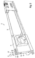
- FIG. 2 shows an embodiment in which the electrical device 1 is designed as a cabinet light.
- the end-side housing portion 11 which is formed substantially parallelepiped-shaped, with a longitudinal side 4, which merges via a corner region 7 in a front side 5, a connector 3 is arranged in the corner region 7, which is recognizable as a male receptacle connector.
- the connector 3 is aligned so that its insertion opening 6 of the longitudinal side 4 of the end-side housing portion 11 faces.
- the recess 8, in which the connector 3 is received, is closed at the end face 5, at least for the most part, by a closure side 10 of the connector housing 9, the closure side 10 being aligned flush with the end face 5.
- the recess 8 could also be on the housing part 11 a one-sided recess, so that the plug forms the outer surface of the housing on one side.
- the connector 3 is analogous to the embodiment according to FIG. 1 again pivotable about an axis of rotation x, so that with its plug-in opening 6 between a first, in FIG. 2 shown, latching position and a second locking position can be pivoted, in which the insertion opening 6 of the end face 5 faces and accordingly the connector end face 12 is aligned with the housing face 5 in alignment or approximately in alignment.
- the connector is thus accessible either via the longitudinal side 4 of the housing 2 or via the end face 5 of the housing 2.
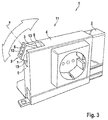
- FIG. 3 shows an enlarged detail of the embodiment according to FIG. 2 , wherein the connector 3 is shown in an intermediate position, in which the connector end face 12 is aligned with the longitudinal side 4 of the housing 2 is still aligned with the end face 5 of the housing. It can be provided that the connector 3 occupies a respective latching position in the two aforementioned setting positions, so that it, once triggered from these locking positions, is substantially freely movable between the latching positions. Depending on the application, it may also be useful for the plug to occupy a latching position in at least one specific intermediate position between the aforementioned latching positions.
- FIG. 3 illustrates that the connector 3 is received in a recess 8 in the corner region 7 of the end-side housing portion 11 of the housing 2, which extends integrally between the longitudinal side 4 and the end face 5, wherein the dimensions of the recess 8 are just chosen so that the connector 3 in each of the two mentioned locking positions the respective access 13 to the recess 8 on each of the sides 4, 5, which faces the connector end face 12 of the connector 3, completely fills and thus closes (see. FIG. 2 ).
- the FIG. 4 serves to illustrate the different parking positions, which can take the connector 3 in one embodiment of the electrical device 1 according to the invention.
- the connector 3 is pivotable about the axis of rotation x between the position which it occupies in the left-hand illustration, and the position which it occupies in the right-hand illustration.
- the connector 3 can also assume any intermediate position.
- the orientation shown in the left-hand illustration of the connector 3, in which the insertion opening 6 faces the longitudinal side 4 of the housing 2 and the one shown in the right-hand illustration Orientation in which the connector 3 of the insertion opening 6 of the end face 5 of the housing 2 faces, each having a detent position.
- FIG. 5 schematically another embodiment of the electrical device 1 according to the invention is illustrated.
- the connector 3 is rotatable about a rotation axis Y, which extends in the longitudinal direction of the electrical device 1.
- the electrical device 1 may be, for example, a control cabinet light.
- the electrical device 1 should not be limited to cabinet lights.
- the electrical device 1 is shown in the plan view of the end face 5.
- the two representations in FIG. 5 show that the connector 3 is pivotable about the axis of rotation Y about 180 °, so that it is accessible in a first setting position via a first longitudinal side 4 for a connecting cable 20.
- the positioning position of the connector 3 is shown, in which the connector 3 via one of two parallel spaced longitudinal sides 14, 15 is accessible.
- the connector 3 can also be arranged to be rotated by about 180 °, so that it is accessible via the further longitudinal side 15 of the two parallel spaced longitudinal sides 14, 15.
- this embodiment is particularly suitable for electrical equipment 1 whose housing 2 is at least partially rectangular in longitudinal cross-section, so that the housing 2 has said two parallel spaced longitudinal sides 14, 15 and beyond a further longitudinal side 4, which the two parallel spaced longitudinal sides 14, 15 connects to each other and is preferably arranged at right angles to this.
- the connector 3 can in the three mentioned orientations, in which he each one of the longitudinal sides 4, 14, 15 faces, so that the connector 3 via the respective longitudinal side 4, 14, 15 is accessible, each having a detent position.
- the connector 3 can assume latching positions in intermediate positions. In the FIG. 5 embodiment shown thus has a particularly high variability with regard to the feeding direction of the connecting cable 20.
- FIG. 6 shows a concrete embodiment of in FIG. 5 schematically illustrated embodiment.
- the connector 3 is received in a connector housing 9, which is formed in an end-side housing portion 11 of the housing 2 of the electrical device 1, here as a cabinet light.
- the plug-in opening 6 of the connector 3 of the longitudinal side 4 facing aligned, so that the insertion opening 6 for a connecting cable (not shown) on the longitudinal side 4 is accessible.
- the connector housing 9 is formed such that it completely fills the recess 8 in which the connector housing 9 is accommodated and, in particular, its housing sides 10 are respectively aligned with the respective longitudinal sides 4, 14, 15 of the end housing section 11.
- the connector end face 12 is arranged in alignment with the longitudinal side 4.
- the connector housing 3 is analogous to that in FIG. 5 shown embodiment about a rotation axis Y rotatable, which extends in the longitudinal direction of the housing 2 and the end-side housing portion 11.
- FIG. 7 is for illustrative purposes a detail view of FIG. 6 shown, in which the connector housing 9 by about 45 ° from the in FIG. 6 pivoted position shown.
- the connector housing 9 is adjustable by about ° between the two adjustment positions, in which the insertion opening 6 once in the plane of the representation in accordance with FIG. 7 front longitudinal side 14 is arranged, and once in the plane of the opposite longitudinal side 15 is arranged.
- FIG. 7 In the teilverschwenkten state, as in FIG. 7 is shown, it can also be seen that the connector housing 9 is received in a recess 8 in the end-side housing portion 11, wherein the comparison with FIG. 6 shows that the dimensions of the connector housing 9 and the recess 8 are just coordinated so that the connector housing at least in the in FIG. 6 shown positioning position completely fills the recess, so that the visible surfaces of the connector housing with the longitudinal sides 4, 1 d, 15 of the end-side housing portion 11 are aligned.
Landscapes
- Engineering & Computer Science (AREA)
- Microelectronics & Electronic Packaging (AREA)
- Power Engineering (AREA)
- Connector Housings Or Holding Contact Members (AREA)
- Details Of Connecting Devices For Male And Female Coupling (AREA)
Abstract
Description
- Die Erfindung geht aus von einem elektrischen Gerät für die Montage im Innern eines Schaltschranks, das einen in einem Gehäuse des Geräts aufgenommenen ein- oder mehrpoligen Steckverbinder für den Anschluss eines elektrischen Leiters mit einer über mindestens eine Seite des Gehäuses frei zugänglichen Stecköffnung aufweist. Ein derartiges elektrisches Gerät ist beispielsweise aus der
DE 296 22 478 U1 bekannt. Ein ähnliches elektrisches Gerät zeigt auch dieDE 202 08 338 U1 . - Ein solches elektrisches Gerät kann beispielsweise eine Schaltschrankleuchte sein, die im Innern eines Schaltschranks montiert ist. Bei den in Schaltschränken üblicherweise eingeschränkten Platzverhältnissen muss der elektrische Anschluss der Leuchte so angeordnet sein, dass die Herstellung einer Steckerverbindung von verschiedenen Richtungen aus möglich ist. Dies ist jedoch häufig immer noch mit einer ungünstigen Kabelführung verbunden, die bei den in Schaltschränken eingeschränkten Platzverhältnissen zu Anschlussproblemen führen kann.
- Es ist daher die Aufgabe der Erfindung, ein elektrisches Gerät für die Montage im Innern eines Schaltschranks bereitzustellen, welches auch unter eingeschränkten Platzverhältnissen den einfachen Anschluss des Geräts an eine elektrische Stromversorgung erlaubt.
- Diese Aufgabe wird erfindungsgemäß durch ein elektrisches Gerät mit den Merkmalen des Anspruchs 1 gelöst. Die abhängigen Ansprüche sind jeweils vorteilhafte Ausführungsformen der Erfindung.
- Demgemäß kann bei dem vorgeschlagenen elektrischen Gerät der Steckverbinder mindestens zwei unterschiedliche Positionen oder Ausrichtungen in Bezug auf das Gehäuse einnehmen. Auf diese Weise wird erreicht, dass je nach vorgefundenen Platzverhältnissen der Steckverbinder so verlagert werden kann, dass unter den gegebenen Umständen eine möglichst optimale Zugänglichkeit des Steckverbinders für einen Anschlussleiter erreicht wird.
- Der Steckverbinder kann beispielsweise ein männlicher oder ein weiblicher Einbausteckverbinder sein, der in einer Seite des elektrischen Geräts verbaut ist.
- Weiterhin kann der Steckverbinder um eine Drehachse verschwenkbar in dem Gehäuse gelagert und über die Drehachse mit dem Gehäuse verbunden sein. So wird trotz der Beweglichkeit des Steckverbinders in dem Gehäuse erreicht, dass der Steckverbinder eine Zugentlastung im Hinblick auf seine elektrische Anbindung an eine elektrische Stromversorgung im Innern des Gehäuses, beispielsweise eine Platine und/oder einen Spannungswandler, besitzt.
- Das Gehäuse kann eine Gehäuseecke aufweisen, an der eine erste und eine zweite Gehäuseseite ineinander übergehen. Die Gehäuseseiten können beispielsweise über eine Kante oder eine Rundung ineinander übergehen. Dabei kann vorgesehen sein, dass die Stecköffnung des Steckverbinders in einer ersten Position oder Ausrichtung der ersten Gehäuseseite zugewandt ist und in einer zweiten Position oder Ausrichtung der zweiten Gehäuseseite zugewandt ist. Die beiden Gehäuseseiten können zum Beispiel im Winkel von etwa 90° zueinander angeordnet sind, so dass der Steckverbinder wahlweise von zwei Raumrichtungen her, beispielsweise von der Seite und von oben, oder von vorne und von unten zugänglich ist, je nachdem, auf welche Weise die bessere Kabelführung erreicht werden kann.
- Das Gehäuse kann auch zwei gegenüberliegende, parallel beabstandete Längsseiten aufweisen, wobei die Stecköffnung des Steckverbinders wiederum in einer ersten Stellposition oder Ausrichtung der ersten Gehäuselängsseite zugewandt ist und in einer zweiten Stellposition oder Ausrichtung der zweiten Gehäuselängsseite zugewandt ist. Dazu kann der Steckverbinder um etwa 180° um eine sich in Längsrichtung des Gehäuses erstreckende Drehachse zwischen der ersten und der zweiten Stellposition oder Ausrichtung verschwenkbar sein. Zusätzlich kann die Stecköffnung des Steckverbinders in einer Zwischenposition, beispielsweise in einer Position, in der der Steckverbinder gegenüber der ersten und der zweiten Stellposition oder Ausrichtung um jeweils etwa 90° um die Drehachse verdreht ist, einer weiteren, die beiden zuvor genannten Gehäuselängsseiten verbindenden Gehäuselängsseite zugewandt sein.
- Die Gehäuseecke bzw. das Gehäuse kann eine Ausnehmung aufweisen, die über jeweils einen Zugang an beiden Gehäuse(längs-)seiten von außerhalb des Gehäuses zugänglich ist und in der der Steckverbinder aufgenommen ist.
- Es ist weiterhin denkbar, dass der Steckverbinder ein Steckverbindergehäuse mit einer Verschlussseite aufweist, die, wenn die Stecköffnung des Steckverbinders einer der beiden Gehäuse(längs-)seiten zugewandt ist, zumindest anteilig den Zugang zu der Ausnehmung in der jeweils anderen Gehäuseseite nach außen verschließt. Dadurch wird erreicht, dass das Innere des Gehäuses, welches auch die elektrische Stromversorgung des Steckverbinders aufweisen kann, von außen nicht zugänglich ist, wodurch ein Berührungsschutz oder auch ein Schutz vor ungewolltem Eindringen von Verschmutzungen und Feuchtigkeit erreicht wird.
- Das Gehäuse kann zumindest in einem endseitigen Gehäuseabschnitt, in dem der Steckverbinder in dem Gehäuse aufgenommen ist, im Wesentlichen quaderförmig ausgebildet sein. Dabei kann der Steckverbinder in einer ersten von zwei um etwa 90° zueinander versetzten Drehpositionen mit seiner Stecköffnung einer Stirnseite des Gehäuses zugewandt sein, wobei der Steckverbinder in einer zweiten der zwei um etwa 90° zueinander versetzten Drehpositionen mit seiner Stecköffnung einer Längsseite des Gehäuses zugewandt ist.
- In den mindestens zwei unterschiedlichen Positionen oder Ausrichtungen, die der Steckverbinder in Bezug auf das Gehäuse einnehmen kann, kann eine Steckverbinderstirnseite eines Steckverbindergehäuses fluchtend mit derjenigen Gehäuseseite ausgerichtet sein, der der Steckverbinder mit seiner Stecköffnung zugewandt ist.
- Weiterhin kann der Steckverbinder zumindest in den mindestens zwei unterschiedlichen Positionen oder Ausrichtungen in Bezug auf das Gehäuse jeweils eine Rastposition einnehmen.
- Für die elektrische Kontaktierung des Steckverbinders mit einer Stromversorgung kann vorgesehen sein, dass der Steckverbinder im Innern des Gehäuses über flexible Leiter mit einer Stromversorgung verbunden ist. Der Steckverbinder kann darüber hinaus auch ganz allgemein mit einer elektrischen funktionalen Baugruppe elektrisch verbunden sein. Anstelle der flexiblen Leiter können auch Schleifkontakte vorgesehen sein, welche das Verlagern des Steckverbinders unter Beibehaltung der elektrischen Kontaktierung erlauben.
- Des Weiteren kann das elektrische Gerät, beispielsweise an zwei gegenüber liegenden Seiten des Gehäuses jeweils einen Steckverbinder der zuvor beschriebenen Art aufweisen. Zwischen diesen Steckverbindern kann eine Durchkontaktierung durch das Gehäuse ausgebildet sein. Dabei können die beiden Steckverbinder identisch oder als ein männlicher und ein weiblicher Steckverbinder ausgebildet sein. Das elektrische Gerät kann beispielsweise an mindestens zwei voneinander beabstandeten Positionen des Gehäuses jeweils einen Steckverbinder aufweisen.
- Weitere Einzelheiten der Erfindung werden anhand der nachstehenden Figuren erläutert. Dabei zeigt:
- Figur 1
- schematisch eine erste Ausführungsform eines elektrischen Geräts, bei dem der Steckverbinder in zwei senkrecht zueinander ausgerichteten Positionen angeordnet ist;
- Figur 2
- eine weitere Ausführungsform eines als Schaltschrankleuchte ausgebildeten elektrischen Geräts in perspektivischer Darstellung;
- Figur 3
- eine Detailansicht der Ausführungsform gemäß
Figur 2 im Bereich des Steckverbinders; - Figur 4
- eine weitere Ausführungsform eines elektrischen Geräts, bei dem zur Veranschaulichung der erfindungsgemäßen Funktion der Steckverbinder beispielhaft in drei unterschiedlichen Stellpositionen dargestellt ist;
- Figur 5
- schematisch noch eine weitere Ausführungsform eines elektrischen Geräts, bei dem der Steckverbinder um eine sich in Längsrichtung des Geräts erstreckende Drehachse verschwenkbar ist;
- Figur 6
- noch eine weitere Ausfuhrungsform eines als Schaltschrankleuchte ausgebildeten elektrischen Geräts in perspektivischer Darstellung; und
- Figur 7
- eine Detailansicht der Ausführungsform gemäß
Figur 6 im Bereich des Steckverbinders. - Die
Figur 1 zeigt schematisch ein elektrisches Gerät, das lediglich beispielhaft als eine Schaltschrankleuchte dargestellt ist, wobei in einem endseitigen Gehäuseabschnitt 11 des Gehäuses 2 des elektrischen Geräts 1 ein um eine senkrecht zur Zeichnungsebene und senkrecht zu den vertikalen Längsseiten des Gehäuses 2 verlaufende Drehachse verschwenkbarer Steckverbinder 3 in einem Eckbereich des Gehäuses 2 aufgenommen ist. Je nachdem, wie eine bessere Kabelführung erreicht werden kann, kann das Anschlusskabel 20 entweder, wie in der oberen Darstellung gezeigt, von der Längsseite 4 dem elektrischen Gerät 1 zugeleitet werden, oder über seine Stirnseite 5 und dazu der Steckverbinder 3 entsprechend entweder der Stirnseite 5 oder der oberen Längsseite 4 zugewandt ausgerichtet werden. Das Anschlusskabel 20 weist endseitig einen männlichen oder weiblichen Stecker auf und der Steckverbinder 3 weist jeweils das entsprechende weibliche oder männliche Gegenstück auf. - Die
Figur 2 zeigt eine Ausführungsform, bei der das elektrische Gerät 1 als eine Schaltschrankleuchte ausgebildet ist. In dem endseitigen Gehäuseabschnitt 11, der im Wesentlichen quaderförmig ausgebildet ist, mit einer Längsseite 4, die über einen Eckbereich 7 in eine Stirnseite 5 übergeht, ist in dem Eckbereich 7 ein Steckverbinder 3 angeordnet, der erkennbar als männlicher Einbausteckverbinder ausgebildet ist. Der Steckverbinder 3 ist so ausgerichtet, dass seine Stecköffnung 6 der Längsseite 4 des endseitigen Gehäuseabschnitts 11 zugewandt ist. Die Ausnehmung 8, in der der Steckverbinder 3 aufgenommen ist, wird an der Stirnseite 5 zumindest größtenteils durch eine Verschlussseite 10 des Steckverbindergehäuses 9 verschlossen, wobei die Verschlussseite 10 gerade mit der Stirnseite 5 fluchtet. Ebenso fluchtet die Steckverbinderstirnseite 12, welche die Stecköffnung 6 aufweist, im Wesentlichen mit der Längsseite 4 des endseitigen Gehäuseabschnitts 11. Die Ausnehmung 8 könnte auch am gehäuseteil 11 eine einseitige Ausnehmung sein, so dass der Stecker auf einer Seite die Außenfläche des Gehäuses bildet. - Der Steckverbinder 3 ist analog zu der Ausführungsform gemäß
Figur 1 wieder um eine Drehachse x derart verschwenkbar, so dass er mit seiner Stecköffnung 6 zwischen einer ersten, inFigur 2 dargestellten, Rastposition und einer zweiten Rastposition verschwenkt werden kann, in der die Stecköffnung 6 der Stirnseite 5 zugewandt ist und dementsprechend die Steckverbinderstirnseite 12 mit der Gehäusestirnseite 5 fluchtend oder annähernd fluchtend ausgerichtet ist. Der Steckverbinder ist somit wahlweise über die Längsseite 4 des Gehäuses 2 oder über die Stirnseite 5 des Gehäuses 2 zugänglich. - Die
Figur 3 zeigt eine Ausschnittsvergrößerung der Ausführungsform gemäßFigur 2 , wobei der Steckverbinder 3 in einer Zwischenstellung gezeigt ist, bei welcher die Steckverbinderstirnseite 12 weder mit der Längsseite 4 des Gehäuses 2 noch mit der Stirnseite 5 des Gehäuses fluchtend ausgerichtet ist. Es kann vorgesehen sein, dass der Steckverbinder 3 in den beiden vorgenannten Stellpositionen jeweils eine Rastposition einnimmt, so dass er, einmal aus diesen Rastpositionen ausgelöst, zwischen den Rastpositionen im Wesentlichen frei beweglich ist. Je nach Anwendung kann es auch sinnvoll sein, dass der Stecker in mindestens einer bestimmten Zwischenpositionen zwischen den zuvor genannten Rastpositionen jeweils eine Rastposition einnimmt. DieFigur 3 veranschaulicht, dass der Steckverbinder 3 in einer Ausnehmung 8 im Eckbereich 7 des endseitigen Gehäuseabschnitts 11 des Gehäuses 2 aufgenommen ist, welche sich zwischen der Längsseite 4 und der Stirnseite 5 einteilig erstreckt, wobei die Abmessungen der Ausnehmung 8 gerade so gewählt sind, dass der Steckverbinder 3 in jeder der beiden erwähnten Rastpositionen den jeweiligen Zugang 13 zu der Ausnehmung 8 an jeder der Seiten 4, 5, welcher die Steckverbinderstirnseite 12 des Steckverbinders 3 jeweils zugewandt ist, vollständig ausfüllt und damit verschließt (vgl.Figur 2 ). - Die
Figur 4 dient zur Veranschaulichung der unterschiedlichen Stellpositionen, die der Steckverbinder 3 bei einer Ausführungsform des erfindungsgemäßen elektrischen Geräts 1 einnehmen kann. Grundsätzlich ist der Steckverbinder 3 um die Drehachse x verschwenkbar zwischen der Position, die er in der linken Darstellung einnimmt, und der Position, die er in der rechten Darstellung einnimmt. Insbesondere kann der Steckverbinder 3 auch jede Zwischenposition einnehmen. Es kann jedoch vorgesehen sein, dass die in der linken Darstellung gezeigte Ausrichtung des Steckverbinders 3, bei der die Stecköffnung 6 der Längsseite 4 des Gehäuses 2 zugewandt ist, und die in der rechten Darstellung gezeigte Ausrichtung, bei der der Steckverbinder 3 der Stecköffnung 6 der Stirnseite 5 des Gehäuses 2 zugewandt ist, jeweils eine Rastposition aufweist. - In
Figur 5 ist schematisch eine weitere Ausführungsform des erfindungsgemäßen elektrischen Geräts 1 veranschaulicht. Im Gegensatz zu den in den vorangegangenen Figuren gezeigten Ausführungsformen ist bei dieser Ausfuhrungsform der Steckverbinder 3 um eine Drehachse Y verdrehbar, welche sich in Längsrichtung des elektrischen Geräts 1 erstreckt. Wie auch in den vorangegangenen Ausführungsformen kann das elektrische Gerät 1 beispielsweise eine Schaltschrankleuchte sein. Das elektrische Gerät 1 soll jedoch nicht auf Schaltschrankleuchten beschränkt sein. InFigur 5 ist das elektrische Gerät 1 in der Draufsicht auf die Stirnseite 5 gezeigt. - Die beiden Darstellungen in
Figur 5 zeigen, dass der Steckverbinder 3 um etwa 180° um die Drehachse Y verschwenkbar ist, so dass er in einer ersten Stellposition über eine erste Längsseite 4 für ein Anschlusskabel 20 zugänglich ist. In der unteren Darstellung vonFigur 5 ist die Stellposition des Steckverbinders 3 gezeigt, bei der der Steckverbinder 3 über eine von zwei parallel beabstandeten Längsseiten 14, 15 zugänglich ist. Analog zu der in der unteren Darstellung vonFigur 5 gezeigten Stellposition des Steckverbinders 3 kann der Steckverbinder 3 auch dazu um etwa 180° verdreht angeordnet sein, so dass er über die weitere Längsseite 15 der beiden parallel beabstandeten Längsseiten 14, 15 zugänglich ist. - Wie in
Figur 5 dargestellt ist, eignet sich diese Ausführungsform insbesondere für elektrische Geräte 1 deren Gehäuse 2 zumindest abschnittsweise im Längsquerschnitt rechteckig ausgebildet ist, so dass das Gehäuse 2 die genannten beiden parallel beabstandeten Längsseiten 14, 15 aufweist und darüber hinaus eine weitere Längsseite 4, welche die beiden parallel beabstandeten Längsseiten 14, 15 miteinander verbindet und vorzugsweise rechtwinklig zu diesen angeordnet ist. - Der Steckverbinder 3 kann in den drei genannten Ausrichtungen, bei denen er jeweils einer der Längsseiten 4, 14, 15 zugewandt ist, so dass der Steckverbinder 3 über die jeweilige Längsseite 4, 14, 15 zugänglich ist, jeweils eine Rastposition aufweisen. Darüber hinaus kann der Steckverbinder 3 auch in Zwischenpositionen Rastpositionen einnehmen. Die in
Figur 5 gezeigte Ausführungsform weist somit eine besonders hohe Variabilität im Hinblick auf die Zuführungsrichtung des Anschlusskabels 20 auf. - Die
Figur 6 zeigt eine konkrete Ausgestaltung der inFigur 5 schematisch dargestellten Ausführungsform. Hierbei ist der Steckverbinder 3 in einem Steckverbindergehäuse 9 aufgenommen, das sich in einem endseitigen Gehäuseabschnitt 11 des Gehäuses 2 des elektrischen Geräts 1, hier als Schaltschrankleuchte ausgebildet, befindet. In der inFigur 6 dargestellten Stellposition ist die Stecköffnung 6 des Steckverbinders 3 der Längsseite 4 zugewandt ausgerichtet, so dass die Stecköffnung 6 für ein Anschlusskabel (nicht dargestellt) über die Längsseite 4 zugänglich ist. Des Weiteren ist das Steckverbindergehäuse 9 so ausgebildet, dass es die Ausnehmung 8 in der das Steckverbindergehäuse 9 aufgenommen ist, vollständig ausfüllt und insbesondere seine Gehäuseseiten 10 jeweils fluchtend zu den jeweiligen Längsseiten 4, 14, 15 des endseitigen Gehäuseabschnitts 11 angeordnet sind. Des Weiteren ist die Steckverbinderstirnseite 12 fluchtend zu der Längsseite 4 angeordnet. - Das Steckverbindergehäuse 3 ist analog zu der in
Figur 5 gezeigten Ausführungsform um eine Drehachse Y verdrehbar, welche sich in Längsrichtung des Gehäuses 2 beziehungsweise des endseitigen Gehäuseabschnitts 11 erstreckt. - In
Figur 7 ist zur Veranschaulichung eine Detailansicht derFigur 6 gezeigt, bei der das Steckverbindergehäuse 9 um ca. 45° aus der inFigur 6 gezeigten Position verschwenkt ist. Das Steckverbindergehäuse 9 ist um etwa ° zwischen den beiden Stellpositionen verstellbar, bei denen die Stecköffnung 6 einmal in der Ebene der in der Darstellung gemäßFigur 7 vorderen Längsseite 14 angeordnet ist, und einmal in der Ebene der gegenüberliegenden Längsseite 15 angeordnet ist. - In dem teilverschwenkten Zustand, wie er in
Figur 7 gezeigt ist, ist auch zu erkennen, dass das Steckverbindergehäuse 9 in einer Ausnehmung 8 in dem endseitigen Gehäuseabschnitt 11 aufgenommen ist, wobei der Vergleich mitFigur 6 zeigt, dass die Abmessungen des Steckverbindergehäuses 9 und der Ausnehmung 8 gerade so aufeinander abgestimmt sind, dass das Steckverbindergehäuse zumindest in der inFigur 6 dargestellten Stellposition die Ausnehmung vollständig ausfüllt, so dass die sichtbaren Flächen des Steckverbindergehäuses mit den Längsseiten 4, 1 d, 15 des endseitigen Gehäuseabschnitts 11 fluchten. - Die in der vorstehenden Beschreibung, in der Zeichnung sowie in den Ansprüchen offenbarten Merkmale der Erfindung können sowohl einzeln als auch in beliebiger Kombination für die Verwirklichung der Erfindung wesentlich sein.
-
- 1
- Elektrisches Gerät
- 2
- Gehäuse
- 3
- Steckverbinder
- 4
- Längsseite
- 5
- Stirnseite
- 6
- Stecköffnung
- 7
- Gehäuseecke
- 8
- Ausnehmung
- 9
- Steckverbindergehäuse
- 10
- Verschlussseite
- 11
- endseitiger Gehäuseabschnitt
- 12
- Steckverbinderstirnseite
- 13
- Zugang
- 20
- Anschlusskabel
- X
- Drehachse
Claims (13)
- Elektrisches Gerät (1) für die Montage im Innern eines Schaltschranks, das mindestens einen in einem Gehäuse (2) des Geräts (1) aufgenommenen ein- oder mehrpoligen Steckverbinder (3) für den Anschluss eines elektrischen Leiters mit einer über eine Seite (4, 5) des Gehäuses (2) frei zugänglichen Stecköffnung (6) aufweist, dadurch gekennzeichnet, dass der mindestens eine Steckverbinder (3) mindestens zwei unterschiedliche Positionen oder Ausrichtungen in Bezug auf das Gehäuse (2) einnehmen kann.
- Elektrisches Gerät (1) nach Anspruch 1, bei dem der Steckverbinder (3) um mindestens eine Drehachse (X, Y) verschwenkbar in dem Gehäuse (2) gelagert und über die Drehachse (X, Y') mit dem Gehäuse (2) verbunden ist.
- Elektrisches Gerät (1) nach einem der Anspruch 1 oder 2, bei dem das Gehäuse (2) eine Gehäuseecke (7) aufweist, an der eine erste und eine zweite Gehäuseseite (4, 5) ineinander übergehen, wobei die Stecköffnung (6) des Steckverbinders (3) in einer ersten Position oder Ausrichtung der ersten Gehäuseseite (4) zugewandt ist, und wobei die Stecköffnung (6) des Steckverbinders (3) in einer zweiten Position oder Ausrichtung der zweiten Gehäuseseite (5) zugewandt ist.
- Elektrisches Gerät (1) nach Anspruch 3, bei dem die Gehäuseecke (7) eine Ausnehmung (8) aufweist, die über jeweils einen Zugang (13) an beiden Gehäuseseiten (4, 5) von außerhalb des Gehäuses (2) zugänglich ist und in der der Steckverbinder (3) aufgenommen ist.
- Elektrisches Gerät (1) nach Anspruch 3 oder 4, bei dem das Gehäuse (2) zumindest in einem endseitigen Gehäuseabschnitt (11), in dem der Steckverbinder (3) in dem Gehäuse (2) aufgenommen ist, im Wesentlichen quaderförmig ausgebildet ist, wobei der Steckverbinder (3) in einer ersten von zwei um 90° zueinander versetzten Drehpositionen mit seiner Stecköffnung (6) einer Stirnseite (5) des Gehäuses (2) zugewandt ist, und wobei der Steckverbinder (3) in einer zweiten der zwei um 90° zueinander versetzten Drehpositionen mit seiner Stecköffnung (6) einer Längsseiteseite (4) des Gehäuses (2) zugewandt ist.
- Elektrisches Gerät (1) nach einem der Anspruch 1 oder 2, bei dem das Gehäuse zwei gegenüberliegende, parallel beabstandete Gehäuselängsseiten (14, 15) aufweist, wobei die Stecköffnung (6) des Steckverbinders (3) in einer ersten Stellposition oder Ausrichtung einer ersten der beiden Gehäuselängsseiten (14, 15) und in einer zweiten Stellposition oder Ausrichtung einer zweiten der beiden Gehäuselängsseiten zugewandt ist.
- Elektrisches Gerät (1) nach Anspruch 6, bei dem der Steckverbinder um 180° um eine sich in Längsrichtung des Gehäuses (2) erstreckende Drehachse (Y) zwischen der ersten und der zweiten Stellposition oder Ausrichtung verschwenkbar ist.
- Elektrisches Gerät (1) nach Anspruch 7, bei dem die Stecköffnung (6) des Steckverbinders (3) in einer Zwischenposition, in der der Steckverbinder (3) gegenüber der ersten und der zweiten Stellposition oder Ausrichtung um jeweils 90° um die Drehachse (Y) verdreht ist, einer weiteren, die beiden Gehäuselängsseiten 0 verbindenden Gehäuselängsseite (14, 15) zugewandt sein.
- Elektrisches Gerät (1) nach einem der Ansprüche 3 bis 8, bei dem das Gehäuse (2) eine Ausnehmung (8) aufweist, die über jeweils einen Zugang (13) an beiden Gehäuseseiten (4, 5, 14, 15) von außerhalb des Gehäuses (2) zugänglich ist und in der der Steckverbinder (3) aufgenommen ist, und bei dem der Steckverbinder (3) ein Steckverbindergehäuse (9) und eine Verschlussseite (10) aufweist, die, wenn die Stecköffnung (6) des Steckverbinders (3) einer der beiden Gehäuseseiten (4, 5, 14, 15) zugewandt ist, zumindest anteilig den Zugang (13) zu der Ausnehmung (8) in der jeweils anderen Gehäuseseite (4, 5) nach außen verschließt.
- Elektrisches Gerät (1) nach einem der vorangegangen Ansprüche, bei dem in den mindestens zwei unterschiedlichen Positionen oder Ausrichtungen, die der Steckverbinder (3) in Bezug auf das Gehäuse (2) einnehmen kann, eine Steckverbinderstirnseite (12) eines Steckverbindergehäuses (9) fluchtend mit derjenigen Gehäuseseite (4, 5, 14, 15) ausgerichtet ist, der der Steckverbinder (3) mit seiner Stecköffnung (6) zugewandt ist.
- Elektrisches Gerät nach einem der vorangegangen Ansprüche, bei dem der Steckverbinder (3) zumindest in den mindestens zwei unterschiedlichen Positionen oder Ausrichtungen in Bezug auf das Gehäuse (2) jeweils eine Rastposition einnimmt.
- Elektrisches Gerät nach einem der vorangegangen Ansprüche, bei dem der Steckverbinder (3) im Innern des Gehäuses (2) über flexible Leiter oder über eine Zwischenplatine mit einer Stromversorgung verbunden ist.
- Elektrisches Gerät nach einem der vorangegangen Ansprüche, das an mindestens zwei voneinander beabstandeten Positionen des Gehäuses (2) jeweils einen Steckverbinder (6) aufweist.
Applications Claiming Priority (1)
| Application Number | Priority Date | Filing Date | Title |
|---|---|---|---|
| DE102015114570.7A DE102015114570A1 (de) | 2015-09-01 | 2015-09-01 | Elektrisches Gerät für die Montage im Innern eines Schaltschranks |
Publications (2)
| Publication Number | Publication Date |
|---|---|
| EP3139454A1 true EP3139454A1 (de) | 2017-03-08 |
| EP3139454B1 EP3139454B1 (de) | 2018-10-17 |
Family
ID=56852120
Family Applications (1)
| Application Number | Title | Priority Date | Filing Date |
|---|---|---|---|
| EP16186380.8A Active EP3139454B1 (de) | 2015-09-01 | 2016-08-30 | Elektrisches gerät für die montage im innern eines schaltschranks |
Country Status (4)
| Country | Link |
|---|---|
| US (1) | US9955601B2 (de) |
| EP (1) | EP3139454B1 (de) |
| CN (1) | CN106410537B (de) |
| DE (1) | DE102015114570A1 (de) |
Families Citing this family (5)
| Publication number | Priority date | Publication date | Assignee | Title |
|---|---|---|---|---|
| DE102016107569A1 (de) | 2016-04-18 | 2017-10-19 | Rittal Gmbh & Co. Kg | Schaltschrankleuchte für die Beleuchtung eines Schaltschrankinnenraums |
| DE102016107147B4 (de) | 2016-04-18 | 2017-11-30 | Rittal Gmbh & Co. Kg | Schaltschrankleuchte mit verstellbarer Leuchtmittelplatine |
| DE102017128352A1 (de) * | 2017-11-30 | 2019-06-06 | HARTING Electronics GmbH | LED-Panel mit Steckverbindern |
| WO2020255935A1 (ja) * | 2019-06-19 | 2020-12-24 | アルプスアルパイン株式会社 | 回転コネクタ |
| CN112103739A (zh) * | 2020-08-10 | 2020-12-18 | 深圳供电局有限公司 | 环网柜出线连接器 |
Citations (4)
| Publication number | Priority date | Publication date | Assignee | Title |
|---|---|---|---|---|
| DE29622478U1 (de) | 1996-12-20 | 1997-09-25 | Planer, Dagmar, 53332 Bornheim | Schaltschrankleuchte mit integrierten Steckvorrichtungen |
| DE20208338U1 (de) | 2002-05-29 | 2002-09-05 | Richter, Jörg, 57567 Daaden | Schaltschrankleuchte |
| US7255582B1 (en) * | 2006-04-21 | 2007-08-14 | Sheng-Hsin Liao | Foldable USB connection port |
| US20120238146A1 (en) * | 2011-03-18 | 2012-09-20 | Wen-Yung Liao | Usb connector |
Family Cites Families (8)
| Publication number | Priority date | Publication date | Assignee | Title |
|---|---|---|---|---|
| DD134824B1 (de) * | 1978-01-31 | 1986-04-23 | Starkstrom Anlagenbau Mgdb Veb | Kabelanschlusseinrichtung fuer steuer- und bedienungspulte |
| US5634806A (en) * | 1994-02-24 | 1997-06-03 | Asian Micro Sources, Inc. | Interchangeable collapsible plug device for battery charger |
| DE202004010287U1 (de) * | 2004-07-01 | 2004-09-16 | Coninvers Elektrotechnische Bauelemente Gmbh | Mehrpoliger elektrischer Steckverbinder |
| DE202005015971U1 (de) * | 2005-10-10 | 2005-12-29 | Coninvers Elektrotechnische Bauelemente Gmbh | Mehrpolige elektrische Steckverbindung |
| US8223483B2 (en) * | 2010-01-04 | 2012-07-17 | Apple Inc. | Dock with moveable connector for display device |
| DE102010041931A1 (de) * | 2010-10-04 | 2012-04-05 | Robert Bosch Gmbh | Elektrischer Clipverbinder, elektrische Clipverbindung sowie konfektioniertes elektrisches Kabel |
| US20120156909A1 (en) * | 2010-12-17 | 2012-06-21 | Tyco Electronics Corporation | Power connector assembly |
| DE112013003687T5 (de) | 2012-07-26 | 2015-04-30 | Server Technology, Inc. | Mehrpositions-Eingangskabel-Anordnung für eine Stromverteilereinheit |
-
2015
- 2015-09-01 DE DE102015114570.7A patent/DE102015114570A1/de not_active Withdrawn
-
2016
- 2016-08-30 EP EP16186380.8A patent/EP3139454B1/de active Active
- 2016-08-31 CN CN201610797853.1A patent/CN106410537B/zh active Active
- 2016-08-31 US US15/252,662 patent/US9955601B2/en active Active
Patent Citations (4)
| Publication number | Priority date | Publication date | Assignee | Title |
|---|---|---|---|---|
| DE29622478U1 (de) | 1996-12-20 | 1997-09-25 | Planer, Dagmar, 53332 Bornheim | Schaltschrankleuchte mit integrierten Steckvorrichtungen |
| DE20208338U1 (de) | 2002-05-29 | 2002-09-05 | Richter, Jörg, 57567 Daaden | Schaltschrankleuchte |
| US7255582B1 (en) * | 2006-04-21 | 2007-08-14 | Sheng-Hsin Liao | Foldable USB connection port |
| US20120238146A1 (en) * | 2011-03-18 | 2012-09-20 | Wen-Yung Liao | Usb connector |
Also Published As
| Publication number | Publication date |
|---|---|
| EP3139454B1 (de) | 2018-10-17 |
| CN106410537B (zh) | 2019-08-16 |
| CN106410537A (zh) | 2017-02-15 |
| DE102015114570A1 (de) | 2017-03-02 |
| US9955601B2 (en) | 2018-04-24 |
| US20170064848A1 (en) | 2017-03-02 |
Similar Documents
| Publication | Publication Date | Title |
|---|---|---|
| EP3734768B1 (de) | Steckverbinder einer elektrischen steckverbindung sowie damit gebildete elektrische steckverbindung | |
| DE102004038123B4 (de) | Elektrischer Stecker und elektrische Steckeraufnahme | |
| DE102013113975C5 (de) | Halterahmen für einen Steckverbinder | |
| DE102016116966B4 (de) | Federkraftklemmanschluss sowie Leiteranschlussklemme | |
| EP3139454B1 (de) | Elektrisches gerät für die montage im innern eines schaltschranks | |
| EP2839544B1 (de) | Prüfklemmenblock | |
| EP3734771B1 (de) | Set aus einer elektrischen steckverbindung und einem funktionselement | |
| EP2823536B1 (de) | Steckverbinder umfassend eine schutzleiterbrücke | |
| DE102009006441A1 (de) | Leichtkraftsteckverbinder | |
| DE102012100815B3 (de) | Elektrisches Kupplungselement | |
| EP3701595A1 (de) | Halterahmen für einen industriesteckverbinder | |
| EP2720325B1 (de) | Schaltbare Steckdose | |
| DE102010017361A1 (de) | Anbausteckverbinder | |
| DE102015217409A1 (de) | lsolationskörper für ein steckbares Verbindungselement | |
| EP1445840A1 (de) | Elektrischer Steckverbinder | |
| EP1372365B1 (de) | Anschlussverbinder | |
| EP3183778A1 (de) | Elektrische anschlussklemme | |
| DE102013022674B4 (de) | Halterahmen für einen Steckverbinder | |
| EP2662936B1 (de) | Vorrichtung zum elektrischen Verbinden von Hauptleitern eines Energieversorgungskabels mit jeweils mindestens einem Abzweigleiter | |
| WO2024240297A1 (de) | Halterahmen für ein steckverbindergehäuse eines industriesteckverbinders | |
| WO2024245492A1 (de) | Befestigungsvorrichtung für funktionseinheiten eines multifunktionalen steckverbindermoduls, multifunktionales steckverbindermodul und steckverbindermodularsystem | |
| DE29503747U1 (de) | Gehäuse | |
| WO2024240295A1 (de) | Steckverbindermodul für einen modularen industriesteckverbinder und system aus steckverbindermodul und steckverbindergehäuse | |
| WO2024240294A1 (de) | Steckverbindermodul zum einsetzen in einen halterahmen eines modularen industriesteckverbinders | |
| WO2026032475A1 (de) | Steckereinsatz |
Legal Events
| Date | Code | Title | Description |
|---|---|---|---|
| PUAI | Public reference made under article 153(3) epc to a published international application that has entered the european phase |
Free format text: ORIGINAL CODE: 0009012 |
|
| STAA | Information on the status of an ep patent application or granted ep patent |
Free format text: STATUS: THE APPLICATION HAS BEEN PUBLISHED |
|
| AK | Designated contracting states |
Kind code of ref document: A1 Designated state(s): AL AT BE BG CH CY CZ DE DK EE ES FI FR GB GR HR HU IE IS IT LI LT LU LV MC MK MT NL NO PL PT RO RS SE SI SK SM TR |
|
| AX | Request for extension of the european patent |
Extension state: BA ME |
|
| STAA | Information on the status of an ep patent application or granted ep patent |
Free format text: STATUS: REQUEST FOR EXAMINATION WAS MADE |
|
| 17P | Request for examination filed |
Effective date: 20170825 |
|
| RBV | Designated contracting states (corrected) |
Designated state(s): AL AT BE BG CH CY CZ DE DK EE ES FI FR GB GR HR HU IE IS IT LI LT LU LV MC MK MT NL NO PL PT RO RS SE SI SK SM TR |
|
| STAA | Information on the status of an ep patent application or granted ep patent |
Free format text: STATUS: EXAMINATION IS IN PROGRESS |
|
| 17Q | First examination report despatched |
Effective date: 20180208 |
|
| GRAP | Despatch of communication of intention to grant a patent |
Free format text: ORIGINAL CODE: EPIDOSNIGR1 |
|
| STAA | Information on the status of an ep patent application or granted ep patent |
Free format text: STATUS: GRANT OF PATENT IS INTENDED |
|
| RIC1 | Information provided on ipc code assigned before grant |
Ipc: H01R 31/06 20060101AFI20180613BHEP Ipc: H05K 5/02 20060101ALI20180613BHEP Ipc: H01R 35/02 20060101ALI20180613BHEP Ipc: H05K 5/00 20060101ALI20180613BHEP |
|
| RIC1 | Information provided on ipc code assigned before grant |
Ipc: H05K 5/02 20060101ALI20180618BHEP Ipc: H05K 5/00 20060101ALI20180618BHEP Ipc: H01R 35/04 20060101ALI20180618BHEP Ipc: H01R 31/06 20060101AFI20180618BHEP |
|
| INTG | Intention to grant announced |
Effective date: 20180704 |
|
| GRAS | Grant fee paid |
Free format text: ORIGINAL CODE: EPIDOSNIGR3 |
|
| GRAA | (expected) grant |
Free format text: ORIGINAL CODE: 0009210 |
|
| STAA | Information on the status of an ep patent application or granted ep patent |
Free format text: STATUS: THE PATENT HAS BEEN GRANTED |
|
| AK | Designated contracting states |
Kind code of ref document: B1 Designated state(s): AL AT BE BG CH CY CZ DE DK EE ES FI FR GB GR HR HU IE IS IT LI LT LU LV MC MK MT NL NO PL PT RO RS SE SI SK SM TR |
|
| REG | Reference to a national code |
Ref country code: GB Ref legal event code: FG4D Free format text: NOT ENGLISH |
|
| REG | Reference to a national code |
Ref country code: CH Ref legal event code: EP |
|
| REG | Reference to a national code |
Ref country code: IE Ref legal event code: FG4D Free format text: LANGUAGE OF EP DOCUMENT: GERMAN |
|
| REG | Reference to a national code |
Ref country code: DE Ref legal event code: R096 Ref document number: 502016002248 Country of ref document: DE Ref country code: AT Ref legal event code: REF Ref document number: 1055099 Country of ref document: AT Kind code of ref document: T Effective date: 20181115 |
|
| REG | Reference to a national code |
Ref country code: NL Ref legal event code: MP Effective date: 20181017 |
|
| REG | Reference to a national code |
Ref country code: LT Ref legal event code: MG4D |
|
| PG25 | Lapsed in a contracting state [announced via postgrant information from national office to epo] |
Ref country code: NL Free format text: LAPSE BECAUSE OF FAILURE TO SUBMIT A TRANSLATION OF THE DESCRIPTION OR TO PAY THE FEE WITHIN THE PRESCRIBED TIME-LIMIT Effective date: 20181017 |
|
| PG25 | Lapsed in a contracting state [announced via postgrant information from national office to epo] |
Ref country code: LV Free format text: LAPSE BECAUSE OF FAILURE TO SUBMIT A TRANSLATION OF THE DESCRIPTION OR TO PAY THE FEE WITHIN THE PRESCRIBED TIME-LIMIT Effective date: 20181017 Ref country code: NO Free format text: LAPSE BECAUSE OF FAILURE TO SUBMIT A TRANSLATION OF THE DESCRIPTION OR TO PAY THE FEE WITHIN THE PRESCRIBED TIME-LIMIT Effective date: 20190117 Ref country code: LT Free format text: LAPSE BECAUSE OF FAILURE TO SUBMIT A TRANSLATION OF THE DESCRIPTION OR TO PAY THE FEE WITHIN THE PRESCRIBED TIME-LIMIT Effective date: 20181017 Ref country code: IS Free format text: LAPSE BECAUSE OF FAILURE TO SUBMIT A TRANSLATION OF THE DESCRIPTION OR TO PAY THE FEE WITHIN THE PRESCRIBED TIME-LIMIT Effective date: 20190217 Ref country code: FI Free format text: LAPSE BECAUSE OF FAILURE TO SUBMIT A TRANSLATION OF THE DESCRIPTION OR TO PAY THE FEE WITHIN THE PRESCRIBED TIME-LIMIT Effective date: 20181017 Ref country code: ES Free format text: LAPSE BECAUSE OF FAILURE TO SUBMIT A TRANSLATION OF THE DESCRIPTION OR TO PAY THE FEE WITHIN THE PRESCRIBED TIME-LIMIT Effective date: 20181017 Ref country code: BG Free format text: LAPSE BECAUSE OF FAILURE TO SUBMIT A TRANSLATION OF THE DESCRIPTION OR TO PAY THE FEE WITHIN THE PRESCRIBED TIME-LIMIT Effective date: 20190117 Ref country code: PL Free format text: LAPSE BECAUSE OF FAILURE TO SUBMIT A TRANSLATION OF THE DESCRIPTION OR TO PAY THE FEE WITHIN THE PRESCRIBED TIME-LIMIT Effective date: 20181017 Ref country code: HR Free format text: LAPSE BECAUSE OF FAILURE TO SUBMIT A TRANSLATION OF THE DESCRIPTION OR TO PAY THE FEE WITHIN THE PRESCRIBED TIME-LIMIT Effective date: 20181017 |
|
| PG25 | Lapsed in a contracting state [announced via postgrant information from national office to epo] |
Ref country code: SE Free format text: LAPSE BECAUSE OF FAILURE TO SUBMIT A TRANSLATION OF THE DESCRIPTION OR TO PAY THE FEE WITHIN THE PRESCRIBED TIME-LIMIT Effective date: 20181017 Ref country code: AL Free format text: LAPSE BECAUSE OF FAILURE TO SUBMIT A TRANSLATION OF THE DESCRIPTION OR TO PAY THE FEE WITHIN THE PRESCRIBED TIME-LIMIT Effective date: 20181017 Ref country code: PT Free format text: LAPSE BECAUSE OF FAILURE TO SUBMIT A TRANSLATION OF THE DESCRIPTION OR TO PAY THE FEE WITHIN THE PRESCRIBED TIME-LIMIT Effective date: 20190217 Ref country code: RS Free format text: LAPSE BECAUSE OF FAILURE TO SUBMIT A TRANSLATION OF THE DESCRIPTION OR TO PAY THE FEE WITHIN THE PRESCRIBED TIME-LIMIT Effective date: 20181017 Ref country code: GR Free format text: LAPSE BECAUSE OF FAILURE TO SUBMIT A TRANSLATION OF THE DESCRIPTION OR TO PAY THE FEE WITHIN THE PRESCRIBED TIME-LIMIT Effective date: 20190118 |
|
| REG | Reference to a national code |
Ref country code: DE Ref legal event code: R097 Ref document number: 502016002248 Country of ref document: DE |
|
| PG25 | Lapsed in a contracting state [announced via postgrant information from national office to epo] |
Ref country code: DK Free format text: LAPSE BECAUSE OF FAILURE TO SUBMIT A TRANSLATION OF THE DESCRIPTION OR TO PAY THE FEE WITHIN THE PRESCRIBED TIME-LIMIT Effective date: 20181017 Ref country code: CZ Free format text: LAPSE BECAUSE OF FAILURE TO SUBMIT A TRANSLATION OF THE DESCRIPTION OR TO PAY THE FEE WITHIN THE PRESCRIBED TIME-LIMIT Effective date: 20181017 |
|
| PLBE | No opposition filed within time limit |
Free format text: ORIGINAL CODE: 0009261 |
|
| STAA | Information on the status of an ep patent application or granted ep patent |
Free format text: STATUS: NO OPPOSITION FILED WITHIN TIME LIMIT |
|
| PG25 | Lapsed in a contracting state [announced via postgrant information from national office to epo] |
Ref country code: RO Free format text: LAPSE BECAUSE OF FAILURE TO SUBMIT A TRANSLATION OF THE DESCRIPTION OR TO PAY THE FEE WITHIN THE PRESCRIBED TIME-LIMIT Effective date: 20181017 Ref country code: EE Free format text: LAPSE BECAUSE OF FAILURE TO SUBMIT A TRANSLATION OF THE DESCRIPTION OR TO PAY THE FEE WITHIN THE PRESCRIBED TIME-LIMIT Effective date: 20181017 Ref country code: SM Free format text: LAPSE BECAUSE OF FAILURE TO SUBMIT A TRANSLATION OF THE DESCRIPTION OR TO PAY THE FEE WITHIN THE PRESCRIBED TIME-LIMIT Effective date: 20181017 Ref country code: SK Free format text: LAPSE BECAUSE OF FAILURE TO SUBMIT A TRANSLATION OF THE DESCRIPTION OR TO PAY THE FEE WITHIN THE PRESCRIBED TIME-LIMIT Effective date: 20181017 |
|
| 26N | No opposition filed |
Effective date: 20190718 |
|
| PG25 | Lapsed in a contracting state [announced via postgrant information from national office to epo] |
Ref country code: SI Free format text: LAPSE BECAUSE OF FAILURE TO SUBMIT A TRANSLATION OF THE DESCRIPTION OR TO PAY THE FEE WITHIN THE PRESCRIBED TIME-LIMIT Effective date: 20181017 |
|
| PG25 | Lapsed in a contracting state [announced via postgrant information from national office to epo] |
Ref country code: TR Free format text: LAPSE BECAUSE OF FAILURE TO SUBMIT A TRANSLATION OF THE DESCRIPTION OR TO PAY THE FEE WITHIN THE PRESCRIBED TIME-LIMIT Effective date: 20181017 |
|
| PG25 | Lapsed in a contracting state [announced via postgrant information from national office to epo] |
Ref country code: MC Free format text: LAPSE BECAUSE OF FAILURE TO SUBMIT A TRANSLATION OF THE DESCRIPTION OR TO PAY THE FEE WITHIN THE PRESCRIBED TIME-LIMIT Effective date: 20181017 Ref country code: CH Free format text: LAPSE BECAUSE OF NON-PAYMENT OF DUE FEES Effective date: 20190831 Ref country code: LI Free format text: LAPSE BECAUSE OF NON-PAYMENT OF DUE FEES Effective date: 20190831 Ref country code: LU Free format text: LAPSE BECAUSE OF NON-PAYMENT OF DUE FEES Effective date: 20190830 |
|
| REG | Reference to a national code |
Ref country code: BE Ref legal event code: MM Effective date: 20190831 |
|
| PG25 | Lapsed in a contracting state [announced via postgrant information from national office to epo] |
Ref country code: IE Free format text: LAPSE BECAUSE OF NON-PAYMENT OF DUE FEES Effective date: 20190830 |
|
| PG25 | Lapsed in a contracting state [announced via postgrant information from national office to epo] |
Ref country code: BE Free format text: LAPSE BECAUSE OF NON-PAYMENT OF DUE FEES Effective date: 20190831 |
|
| GBPC | Gb: european patent ceased through non-payment of renewal fee |
Effective date: 20200830 |
|
| PG25 | Lapsed in a contracting state [announced via postgrant information from national office to epo] |
Ref country code: CY Free format text: LAPSE BECAUSE OF FAILURE TO SUBMIT A TRANSLATION OF THE DESCRIPTION OR TO PAY THE FEE WITHIN THE PRESCRIBED TIME-LIMIT Effective date: 20181017 |
|
| PG25 | Lapsed in a contracting state [announced via postgrant information from national office to epo] |
Ref country code: HU Free format text: LAPSE BECAUSE OF FAILURE TO SUBMIT A TRANSLATION OF THE DESCRIPTION OR TO PAY THE FEE WITHIN THE PRESCRIBED TIME-LIMIT; INVALID AB INITIO Effective date: 20160830 Ref country code: MT Free format text: LAPSE BECAUSE OF FAILURE TO SUBMIT A TRANSLATION OF THE DESCRIPTION OR TO PAY THE FEE WITHIN THE PRESCRIBED TIME-LIMIT Effective date: 20181017 |
|
| PG25 | Lapsed in a contracting state [announced via postgrant information from national office to epo] |
Ref country code: GB Free format text: LAPSE BECAUSE OF NON-PAYMENT OF DUE FEES Effective date: 20200830 |
|
| PG25 | Lapsed in a contracting state [announced via postgrant information from national office to epo] |
Ref country code: MK Free format text: LAPSE BECAUSE OF FAILURE TO SUBMIT A TRANSLATION OF THE DESCRIPTION OR TO PAY THE FEE WITHIN THE PRESCRIBED TIME-LIMIT Effective date: 20181017 |
|
| REG | Reference to a national code |
Ref country code: AT Ref legal event code: MM01 Ref document number: 1055099 Country of ref document: AT Kind code of ref document: T Effective date: 20210830 |
|
| PG25 | Lapsed in a contracting state [announced via postgrant information from national office to epo] |
Ref country code: AT Free format text: LAPSE BECAUSE OF NON-PAYMENT OF DUE FEES Effective date: 20210830 |
|
| P01 | Opt-out of the competence of the unified patent court (upc) registered |
Effective date: 20230525 |
|
| PGFP | Annual fee paid to national office [announced via postgrant information from national office to epo] |
Ref country code: DE Payment date: 20250819 Year of fee payment: 10 |
|
| PGFP | Annual fee paid to national office [announced via postgrant information from national office to epo] |
Ref country code: IT Payment date: 20250829 Year of fee payment: 10 |
|
| PGFP | Annual fee paid to national office [announced via postgrant information from national office to epo] |
Ref country code: FR Payment date: 20250821 Year of fee payment: 10 |