EP3138713A1 - Hybrid vehicle - Google Patents
Hybrid vehicle Download PDFInfo
- Publication number
- EP3138713A1 EP3138713A1 EP16186490.5A EP16186490A EP3138713A1 EP 3138713 A1 EP3138713 A1 EP 3138713A1 EP 16186490 A EP16186490 A EP 16186490A EP 3138713 A1 EP3138713 A1 EP 3138713A1
- Authority
- EP
- European Patent Office
- Prior art keywords
- electric
- battery
- electric motor
- thermal engine
- charging power
- Prior art date
- Legal status (The legal status is an assumption and is not a legal conclusion. Google has not performed a legal analysis and makes no representation as to the accuracy of the status listed.)
- Granted
Links
Images


Classifications
-
- B—PERFORMING OPERATIONS; TRANSPORTING
- B60—VEHICLES IN GENERAL
- B60W—CONJOINT CONTROL OF VEHICLE SUB-UNITS OF DIFFERENT TYPE OR DIFFERENT FUNCTION; CONTROL SYSTEMS SPECIALLY ADAPTED FOR HYBRID VEHICLES; ROAD VEHICLE DRIVE CONTROL SYSTEMS FOR PURPOSES NOT RELATED TO THE CONTROL OF A PARTICULAR SUB-UNIT
- B60W20/00—Control systems specially adapted for hybrid vehicles
- B60W20/10—Controlling the power contribution of each of the prime movers to meet required power demand
- B60W20/13—Controlling the power contribution of each of the prime movers to meet required power demand in order to stay within battery power input or output limits; in order to prevent overcharging or battery depletion
- B60W20/14—Controlling the power contribution of each of the prime movers to meet required power demand in order to stay within battery power input or output limits; in order to prevent overcharging or battery depletion in conjunction with braking regeneration
-
- B—PERFORMING OPERATIONS; TRANSPORTING
- B60—VEHICLES IN GENERAL
- B60K—ARRANGEMENT OR MOUNTING OF PROPULSION UNITS OR OF TRANSMISSIONS IN VEHICLES; ARRANGEMENT OR MOUNTING OF PLURAL DIVERSE PRIME-MOVERS IN VEHICLES; AUXILIARY DRIVES FOR VEHICLES; INSTRUMENTATION OR DASHBOARDS FOR VEHICLES; ARRANGEMENTS IN CONNECTION WITH COOLING, AIR INTAKE, GAS EXHAUST OR FUEL SUPPLY OF PROPULSION UNITS IN VEHICLES
- B60K6/00—Arrangement or mounting of plural diverse prime-movers for mutual or common propulsion, e.g. hybrid propulsion systems comprising electric motors and internal combustion engines ; Control systems therefor, i.e. systems controlling two or more prime movers, or controlling one of these prime movers and any of the transmission, drive or drive units Informative references: mechanical gearings with secondary electric drive F16H3/72; arrangements for handling mechanical energy structurally associated with the dynamo-electric machine H02K7/00; machines comprising structurally interrelated motor and generator parts H02K51/00; dynamo-electric machines not otherwise provided for in H02K see H02K99/00
- B60K6/20—Arrangement or mounting of plural diverse prime-movers for mutual or common propulsion, e.g. hybrid propulsion systems comprising electric motors and internal combustion engines ; Control systems therefor, i.e. systems controlling two or more prime movers, or controlling one of these prime movers and any of the transmission, drive or drive units Informative references: mechanical gearings with secondary electric drive F16H3/72; arrangements for handling mechanical energy structurally associated with the dynamo-electric machine H02K7/00; machines comprising structurally interrelated motor and generator parts H02K51/00; dynamo-electric machines not otherwise provided for in H02K see H02K99/00 the prime-movers consisting of electric motors and internal combustion engines, e.g. HEVs
- B60K6/22—Arrangement or mounting of plural diverse prime-movers for mutual or common propulsion, e.g. hybrid propulsion systems comprising electric motors and internal combustion engines ; Control systems therefor, i.e. systems controlling two or more prime movers, or controlling one of these prime movers and any of the transmission, drive or drive units Informative references: mechanical gearings with secondary electric drive F16H3/72; arrangements for handling mechanical energy structurally associated with the dynamo-electric machine H02K7/00; machines comprising structurally interrelated motor and generator parts H02K51/00; dynamo-electric machines not otherwise provided for in H02K see H02K99/00 the prime-movers consisting of electric motors and internal combustion engines, e.g. HEVs characterised by apparatus, components or means specially adapted for HEVs
- B60K6/36—Arrangement or mounting of plural diverse prime-movers for mutual or common propulsion, e.g. hybrid propulsion systems comprising electric motors and internal combustion engines ; Control systems therefor, i.e. systems controlling two or more prime movers, or controlling one of these prime movers and any of the transmission, drive or drive units Informative references: mechanical gearings with secondary electric drive F16H3/72; arrangements for handling mechanical energy structurally associated with the dynamo-electric machine H02K7/00; machines comprising structurally interrelated motor and generator parts H02K51/00; dynamo-electric machines not otherwise provided for in H02K see H02K99/00 the prime-movers consisting of electric motors and internal combustion engines, e.g. HEVs characterised by apparatus, components or means specially adapted for HEVs characterised by the transmission gearings
- B60K6/365—Arrangement or mounting of plural diverse prime-movers for mutual or common propulsion, e.g. hybrid propulsion systems comprising electric motors and internal combustion engines ; Control systems therefor, i.e. systems controlling two or more prime movers, or controlling one of these prime movers and any of the transmission, drive or drive units Informative references: mechanical gearings with secondary electric drive F16H3/72; arrangements for handling mechanical energy structurally associated with the dynamo-electric machine H02K7/00; machines comprising structurally interrelated motor and generator parts H02K51/00; dynamo-electric machines not otherwise provided for in H02K see H02K99/00 the prime-movers consisting of electric motors and internal combustion engines, e.g. HEVs characterised by apparatus, components or means specially adapted for HEVs characterised by the transmission gearings with the gears having orbital motion
-
- B—PERFORMING OPERATIONS; TRANSPORTING
- B60—VEHICLES IN GENERAL
- B60K—ARRANGEMENT OR MOUNTING OF PROPULSION UNITS OR OF TRANSMISSIONS IN VEHICLES; ARRANGEMENT OR MOUNTING OF PLURAL DIVERSE PRIME-MOVERS IN VEHICLES; AUXILIARY DRIVES FOR VEHICLES; INSTRUMENTATION OR DASHBOARDS FOR VEHICLES; ARRANGEMENTS IN CONNECTION WITH COOLING, AIR INTAKE, GAS EXHAUST OR FUEL SUPPLY OF PROPULSION UNITS IN VEHICLES
- B60K6/00—Arrangement or mounting of plural diverse prime-movers for mutual or common propulsion, e.g. hybrid propulsion systems comprising electric motors and internal combustion engines ; Control systems therefor, i.e. systems controlling two or more prime movers, or controlling one of these prime movers and any of the transmission, drive or drive units Informative references: mechanical gearings with secondary electric drive F16H3/72; arrangements for handling mechanical energy structurally associated with the dynamo-electric machine H02K7/00; machines comprising structurally interrelated motor and generator parts H02K51/00; dynamo-electric machines not otherwise provided for in H02K see H02K99/00
- B60K6/20—Arrangement or mounting of plural diverse prime-movers for mutual or common propulsion, e.g. hybrid propulsion systems comprising electric motors and internal combustion engines ; Control systems therefor, i.e. systems controlling two or more prime movers, or controlling one of these prime movers and any of the transmission, drive or drive units Informative references: mechanical gearings with secondary electric drive F16H3/72; arrangements for handling mechanical energy structurally associated with the dynamo-electric machine H02K7/00; machines comprising structurally interrelated motor and generator parts H02K51/00; dynamo-electric machines not otherwise provided for in H02K see H02K99/00 the prime-movers consisting of electric motors and internal combustion engines, e.g. HEVs
- B60K6/22—Arrangement or mounting of plural diverse prime-movers for mutual or common propulsion, e.g. hybrid propulsion systems comprising electric motors and internal combustion engines ; Control systems therefor, i.e. systems controlling two or more prime movers, or controlling one of these prime movers and any of the transmission, drive or drive units Informative references: mechanical gearings with secondary electric drive F16H3/72; arrangements for handling mechanical energy structurally associated with the dynamo-electric machine H02K7/00; machines comprising structurally interrelated motor and generator parts H02K51/00; dynamo-electric machines not otherwise provided for in H02K see H02K99/00 the prime-movers consisting of electric motors and internal combustion engines, e.g. HEVs characterised by apparatus, components or means specially adapted for HEVs
- B60K6/38—Arrangement or mounting of plural diverse prime-movers for mutual or common propulsion, e.g. hybrid propulsion systems comprising electric motors and internal combustion engines ; Control systems therefor, i.e. systems controlling two or more prime movers, or controlling one of these prime movers and any of the transmission, drive or drive units Informative references: mechanical gearings with secondary electric drive F16H3/72; arrangements for handling mechanical energy structurally associated with the dynamo-electric machine H02K7/00; machines comprising structurally interrelated motor and generator parts H02K51/00; dynamo-electric machines not otherwise provided for in H02K see H02K99/00 the prime-movers consisting of electric motors and internal combustion engines, e.g. HEVs characterised by apparatus, components or means specially adapted for HEVs characterised by the driveline clutches
- B60K6/387—Actuated clutches, i.e. clutches engaged or disengaged by electric, hydraulic or mechanical actuating means
-
- B—PERFORMING OPERATIONS; TRANSPORTING
- B60—VEHICLES IN GENERAL
- B60K—ARRANGEMENT OR MOUNTING OF PROPULSION UNITS OR OF TRANSMISSIONS IN VEHICLES; ARRANGEMENT OR MOUNTING OF PLURAL DIVERSE PRIME-MOVERS IN VEHICLES; AUXILIARY DRIVES FOR VEHICLES; INSTRUMENTATION OR DASHBOARDS FOR VEHICLES; ARRANGEMENTS IN CONNECTION WITH COOLING, AIR INTAKE, GAS EXHAUST OR FUEL SUPPLY OF PROPULSION UNITS IN VEHICLES
- B60K6/00—Arrangement or mounting of plural diverse prime-movers for mutual or common propulsion, e.g. hybrid propulsion systems comprising electric motors and internal combustion engines ; Control systems therefor, i.e. systems controlling two or more prime movers, or controlling one of these prime movers and any of the transmission, drive or drive units Informative references: mechanical gearings with secondary electric drive F16H3/72; arrangements for handling mechanical energy structurally associated with the dynamo-electric machine H02K7/00; machines comprising structurally interrelated motor and generator parts H02K51/00; dynamo-electric machines not otherwise provided for in H02K see H02K99/00
- B60K6/20—Arrangement or mounting of plural diverse prime-movers for mutual or common propulsion, e.g. hybrid propulsion systems comprising electric motors and internal combustion engines ; Control systems therefor, i.e. systems controlling two or more prime movers, or controlling one of these prime movers and any of the transmission, drive or drive units Informative references: mechanical gearings with secondary electric drive F16H3/72; arrangements for handling mechanical energy structurally associated with the dynamo-electric machine H02K7/00; machines comprising structurally interrelated motor and generator parts H02K51/00; dynamo-electric machines not otherwise provided for in H02K see H02K99/00 the prime-movers consisting of electric motors and internal combustion engines, e.g. HEVs
- B60K6/42—Arrangement or mounting of plural diverse prime-movers for mutual or common propulsion, e.g. hybrid propulsion systems comprising electric motors and internal combustion engines ; Control systems therefor, i.e. systems controlling two or more prime movers, or controlling one of these prime movers and any of the transmission, drive or drive units Informative references: mechanical gearings with secondary electric drive F16H3/72; arrangements for handling mechanical energy structurally associated with the dynamo-electric machine H02K7/00; machines comprising structurally interrelated motor and generator parts H02K51/00; dynamo-electric machines not otherwise provided for in H02K see H02K99/00 the prime-movers consisting of electric motors and internal combustion engines, e.g. HEVs characterised by the architecture of the hybrid electric vehicle
- B60K6/44—Series-parallel type
- B60K6/445—Differential gearing distribution type
-
- B—PERFORMING OPERATIONS; TRANSPORTING
- B60—VEHICLES IN GENERAL
- B60W—CONJOINT CONTROL OF VEHICLE SUB-UNITS OF DIFFERENT TYPE OR DIFFERENT FUNCTION; CONTROL SYSTEMS SPECIALLY ADAPTED FOR HYBRID VEHICLES; ROAD VEHICLE DRIVE CONTROL SYSTEMS FOR PURPOSES NOT RELATED TO THE CONTROL OF A PARTICULAR SUB-UNIT
- B60W10/00—Conjoint control of vehicle sub-units of different type or different function
- B60W10/04—Conjoint control of vehicle sub-units of different type or different function including control of propulsion units
- B60W10/06—Conjoint control of vehicle sub-units of different type or different function including control of propulsion units including control of combustion engines
-
- B—PERFORMING OPERATIONS; TRANSPORTING
- B60—VEHICLES IN GENERAL
- B60W—CONJOINT CONTROL OF VEHICLE SUB-UNITS OF DIFFERENT TYPE OR DIFFERENT FUNCTION; CONTROL SYSTEMS SPECIALLY ADAPTED FOR HYBRID VEHICLES; ROAD VEHICLE DRIVE CONTROL SYSTEMS FOR PURPOSES NOT RELATED TO THE CONTROL OF A PARTICULAR SUB-UNIT
- B60W10/00—Conjoint control of vehicle sub-units of different type or different function
- B60W10/04—Conjoint control of vehicle sub-units of different type or different function including control of propulsion units
- B60W10/08—Conjoint control of vehicle sub-units of different type or different function including control of propulsion units including control of electric propulsion units, e.g. motors or generators
-
- B—PERFORMING OPERATIONS; TRANSPORTING
- B60—VEHICLES IN GENERAL
- B60W—CONJOINT CONTROL OF VEHICLE SUB-UNITS OF DIFFERENT TYPE OR DIFFERENT FUNCTION; CONTROL SYSTEMS SPECIALLY ADAPTED FOR HYBRID VEHICLES; ROAD VEHICLE DRIVE CONTROL SYSTEMS FOR PURPOSES NOT RELATED TO THE CONTROL OF A PARTICULAR SUB-UNIT
- B60W10/00—Conjoint control of vehicle sub-units of different type or different function
- B60W10/18—Conjoint control of vehicle sub-units of different type or different function including control of braking systems
-
- B—PERFORMING OPERATIONS; TRANSPORTING
- B60—VEHICLES IN GENERAL
- B60W—CONJOINT CONTROL OF VEHICLE SUB-UNITS OF DIFFERENT TYPE OR DIFFERENT FUNCTION; CONTROL SYSTEMS SPECIALLY ADAPTED FOR HYBRID VEHICLES; ROAD VEHICLE DRIVE CONTROL SYSTEMS FOR PURPOSES NOT RELATED TO THE CONTROL OF A PARTICULAR SUB-UNIT
- B60W10/00—Conjoint control of vehicle sub-units of different type or different function
- B60W10/24—Conjoint control of vehicle sub-units of different type or different function including control of energy storage means
- B60W10/26—Conjoint control of vehicle sub-units of different type or different function including control of energy storage means for electrical energy, e.g. batteries or capacitors
-
- B—PERFORMING OPERATIONS; TRANSPORTING
- B60—VEHICLES IN GENERAL
- B60W—CONJOINT CONTROL OF VEHICLE SUB-UNITS OF DIFFERENT TYPE OR DIFFERENT FUNCTION; CONTROL SYSTEMS SPECIALLY ADAPTED FOR HYBRID VEHICLES; ROAD VEHICLE DRIVE CONTROL SYSTEMS FOR PURPOSES NOT RELATED TO THE CONTROL OF A PARTICULAR SUB-UNIT
- B60W40/00—Estimation or calculation of non-directly measurable driving parameters for road vehicle drive control systems not related to the control of a particular sub unit, e.g. by using mathematical models
- B60W40/10—Estimation or calculation of non-directly measurable driving parameters for road vehicle drive control systems not related to the control of a particular sub unit, e.g. by using mathematical models related to vehicle motion
- B60W40/105—Speed
-
- B—PERFORMING OPERATIONS; TRANSPORTING
- B60—VEHICLES IN GENERAL
- B60W—CONJOINT CONTROL OF VEHICLE SUB-UNITS OF DIFFERENT TYPE OR DIFFERENT FUNCTION; CONTROL SYSTEMS SPECIALLY ADAPTED FOR HYBRID VEHICLES; ROAD VEHICLE DRIVE CONTROL SYSTEMS FOR PURPOSES NOT RELATED TO THE CONTROL OF A PARTICULAR SUB-UNIT
- B60W2510/00—Input parameters relating to a particular sub-units
- B60W2510/06—Combustion engines, Gas turbines
- B60W2510/0638—Engine speed
-
- B—PERFORMING OPERATIONS; TRANSPORTING
- B60—VEHICLES IN GENERAL
- B60W—CONJOINT CONTROL OF VEHICLE SUB-UNITS OF DIFFERENT TYPE OR DIFFERENT FUNCTION; CONTROL SYSTEMS SPECIALLY ADAPTED FOR HYBRID VEHICLES; ROAD VEHICLE DRIVE CONTROL SYSTEMS FOR PURPOSES NOT RELATED TO THE CONTROL OF A PARTICULAR SUB-UNIT
- B60W2510/00—Input parameters relating to a particular sub-units
- B60W2510/10—Change speed gearings
- B60W2510/1005—Transmission ratio engaged
-
- B—PERFORMING OPERATIONS; TRANSPORTING
- B60—VEHICLES IN GENERAL
- B60W—CONJOINT CONTROL OF VEHICLE SUB-UNITS OF DIFFERENT TYPE OR DIFFERENT FUNCTION; CONTROL SYSTEMS SPECIALLY ADAPTED FOR HYBRID VEHICLES; ROAD VEHICLE DRIVE CONTROL SYSTEMS FOR PURPOSES NOT RELATED TO THE CONTROL OF A PARTICULAR SUB-UNIT
- B60W2510/00—Input parameters relating to a particular sub-units
- B60W2510/24—Energy storage means
- B60W2510/242—Energy storage means for electrical energy
- B60W2510/244—Charge state
-
- B—PERFORMING OPERATIONS; TRANSPORTING
- B60—VEHICLES IN GENERAL
- B60W—CONJOINT CONTROL OF VEHICLE SUB-UNITS OF DIFFERENT TYPE OR DIFFERENT FUNCTION; CONTROL SYSTEMS SPECIALLY ADAPTED FOR HYBRID VEHICLES; ROAD VEHICLE DRIVE CONTROL SYSTEMS FOR PURPOSES NOT RELATED TO THE CONTROL OF A PARTICULAR SUB-UNIT
- B60W2510/00—Input parameters relating to a particular sub-units
- B60W2510/24—Energy storage means
- B60W2510/242—Energy storage means for electrical energy
- B60W2510/246—Temperature
-
- B—PERFORMING OPERATIONS; TRANSPORTING
- B60—VEHICLES IN GENERAL
- B60W—CONJOINT CONTROL OF VEHICLE SUB-UNITS OF DIFFERENT TYPE OR DIFFERENT FUNCTION; CONTROL SYSTEMS SPECIALLY ADAPTED FOR HYBRID VEHICLES; ROAD VEHICLE DRIVE CONTROL SYSTEMS FOR PURPOSES NOT RELATED TO THE CONTROL OF A PARTICULAR SUB-UNIT
- B60W2520/00—Input parameters relating to overall vehicle dynamics
- B60W2520/10—Longitudinal speed
-
- B—PERFORMING OPERATIONS; TRANSPORTING
- B60—VEHICLES IN GENERAL
- B60W—CONJOINT CONTROL OF VEHICLE SUB-UNITS OF DIFFERENT TYPE OR DIFFERENT FUNCTION; CONTROL SYSTEMS SPECIALLY ADAPTED FOR HYBRID VEHICLES; ROAD VEHICLE DRIVE CONTROL SYSTEMS FOR PURPOSES NOT RELATED TO THE CONTROL OF A PARTICULAR SUB-UNIT
- B60W2540/00—Input parameters relating to occupants
- B60W2540/10—Accelerator pedal position
-
- B—PERFORMING OPERATIONS; TRANSPORTING
- B60—VEHICLES IN GENERAL
- B60W—CONJOINT CONTROL OF VEHICLE SUB-UNITS OF DIFFERENT TYPE OR DIFFERENT FUNCTION; CONTROL SYSTEMS SPECIALLY ADAPTED FOR HYBRID VEHICLES; ROAD VEHICLE DRIVE CONTROL SYSTEMS FOR PURPOSES NOT RELATED TO THE CONTROL OF A PARTICULAR SUB-UNIT
- B60W2540/00—Input parameters relating to occupants
- B60W2540/16—Ratio selector position
-
- B—PERFORMING OPERATIONS; TRANSPORTING
- B60—VEHICLES IN GENERAL
- B60W—CONJOINT CONTROL OF VEHICLE SUB-UNITS OF DIFFERENT TYPE OR DIFFERENT FUNCTION; CONTROL SYSTEMS SPECIALLY ADAPTED FOR HYBRID VEHICLES; ROAD VEHICLE DRIVE CONTROL SYSTEMS FOR PURPOSES NOT RELATED TO THE CONTROL OF A PARTICULAR SUB-UNIT
- B60W2710/00—Output or target parameters relating to a particular sub-units
- B60W2710/06—Combustion engines, Gas turbines
- B60W2710/0616—Position of fuel or air injector
- B60W2710/0627—Fuel flow rate
-
- B—PERFORMING OPERATIONS; TRANSPORTING
- B60—VEHICLES IN GENERAL
- B60W—CONJOINT CONTROL OF VEHICLE SUB-UNITS OF DIFFERENT TYPE OR DIFFERENT FUNCTION; CONTROL SYSTEMS SPECIALLY ADAPTED FOR HYBRID VEHICLES; ROAD VEHICLE DRIVE CONTROL SYSTEMS FOR PURPOSES NOT RELATED TO THE CONTROL OF A PARTICULAR SUB-UNIT
- B60W2710/00—Output or target parameters relating to a particular sub-units
- B60W2710/06—Combustion engines, Gas turbines
- B60W2710/0644—Engine speed
-
- B—PERFORMING OPERATIONS; TRANSPORTING
- B60—VEHICLES IN GENERAL
- B60W—CONJOINT CONTROL OF VEHICLE SUB-UNITS OF DIFFERENT TYPE OR DIFFERENT FUNCTION; CONTROL SYSTEMS SPECIALLY ADAPTED FOR HYBRID VEHICLES; ROAD VEHICLE DRIVE CONTROL SYSTEMS FOR PURPOSES NOT RELATED TO THE CONTROL OF A PARTICULAR SUB-UNIT
- B60W2710/00—Output or target parameters relating to a particular sub-units
- B60W2710/08—Electric propulsion units
- B60W2710/083—Torque
-
- B—PERFORMING OPERATIONS; TRANSPORTING
- B60—VEHICLES IN GENERAL
- B60W—CONJOINT CONTROL OF VEHICLE SUB-UNITS OF DIFFERENT TYPE OR DIFFERENT FUNCTION; CONTROL SYSTEMS SPECIALLY ADAPTED FOR HYBRID VEHICLES; ROAD VEHICLE DRIVE CONTROL SYSTEMS FOR PURPOSES NOT RELATED TO THE CONTROL OF A PARTICULAR SUB-UNIT
- B60W2710/00—Output or target parameters relating to a particular sub-units
- B60W2710/18—Braking system
-
- B—PERFORMING OPERATIONS; TRANSPORTING
- B60—VEHICLES IN GENERAL
- B60W—CONJOINT CONTROL OF VEHICLE SUB-UNITS OF DIFFERENT TYPE OR DIFFERENT FUNCTION; CONTROL SYSTEMS SPECIALLY ADAPTED FOR HYBRID VEHICLES; ROAD VEHICLE DRIVE CONTROL SYSTEMS FOR PURPOSES NOT RELATED TO THE CONTROL OF A PARTICULAR SUB-UNIT
- B60W2710/00—Output or target parameters relating to a particular sub-units
- B60W2710/24—Energy storage means
- B60W2710/242—Energy storage means for electrical energy
- B60W2710/244—Charge state
-
- B—PERFORMING OPERATIONS; TRANSPORTING
- B60—VEHICLES IN GENERAL
- B60W—CONJOINT CONTROL OF VEHICLE SUB-UNITS OF DIFFERENT TYPE OR DIFFERENT FUNCTION; CONTROL SYSTEMS SPECIALLY ADAPTED FOR HYBRID VEHICLES; ROAD VEHICLE DRIVE CONTROL SYSTEMS FOR PURPOSES NOT RELATED TO THE CONTROL OF A PARTICULAR SUB-UNIT
- B60W2710/00—Output or target parameters relating to a particular sub-units
- B60W2710/24—Energy storage means
- B60W2710/242—Energy storage means for electrical energy
- B60W2710/248—Current for loading or unloading
-
- Y—GENERAL TAGGING OF NEW TECHNOLOGICAL DEVELOPMENTS; GENERAL TAGGING OF CROSS-SECTIONAL TECHNOLOGIES SPANNING OVER SEVERAL SECTIONS OF THE IPC; TECHNICAL SUBJECTS COVERED BY FORMER USPC CROSS-REFERENCE ART COLLECTIONS [XRACs] AND DIGESTS
- Y02—TECHNOLOGIES OR APPLICATIONS FOR MITIGATION OR ADAPTATION AGAINST CLIMATE CHANGE
- Y02T—CLIMATE CHANGE MITIGATION TECHNOLOGIES RELATED TO TRANSPORTATION
- Y02T10/00—Road transport of goods or passengers
- Y02T10/60—Other road transportation technologies with climate change mitigation effect
- Y02T10/62—Hybrid vehicles
-
- Y—GENERAL TAGGING OF NEW TECHNOLOGICAL DEVELOPMENTS; GENERAL TAGGING OF CROSS-SECTIONAL TECHNOLOGIES SPANNING OVER SEVERAL SECTIONS OF THE IPC; TECHNICAL SUBJECTS COVERED BY FORMER USPC CROSS-REFERENCE ART COLLECTIONS [XRACs] AND DIGESTS
- Y02—TECHNOLOGIES OR APPLICATIONS FOR MITIGATION OR ADAPTATION AGAINST CLIMATE CHANGE
- Y02T—CLIMATE CHANGE MITIGATION TECHNOLOGIES RELATED TO TRANSPORTATION
- Y02T10/00—Road transport of goods or passengers
- Y02T10/60—Other road transportation technologies with climate change mitigation effect
- Y02T10/72—Electric energy management in electromobility
Definitions
- the present disclosure relates to a hybrid vehicle.
- JP 2014-125078 A discloses such a hybrid vehicle that is configured by including: an thermal engine; a first electric motor; a planetary gear that includes a sun gear, a carrier, and a ring gear connected to the first electric motor, the thermal engine, and a drive shaft that is coupled to an axle; a second electric motor that is connected to the drive shaft; and a battery that supplies/receives electric power to/from the first electric motor and the second electric motor, and applies a braking force to the vehicle by regenerative drive of the second electric motor and motoring of the thermal engine, which is in a state where fuel injection is stopped, by the first electric motor when an accelerator is off.
- excess charging of the battery is prevented by motoring of the thermal engine by the first electric motor, so as to consume the electricity by the first electric motor when the accelerator is off.
- deterioration of the battery is likely to be promoted when the battery is continuously charged with relatively high electric charging power (charge current). Accordingly, in order to prevent an increased deterioration of the battery, when the battery is continuously charged, a permissible electric charging power to the battery is set such that a time period from beginning of the charging to beginning of a rapid decrease in the charged electricity is shortened and a decrease amount per unit time (a decreased rate) at the beginning of the rapid decrease in the electric charging power is increased in correspondence to an increased electric charging power to the battery.
- the electric charging power starts being rapidly decreased, an thermal engine speed has to be rapidly increased, and consumed electricity by the first electric motor has to be rapidly increased.
- an increase amount in the thermal engine speed per unit time is relatively large, a driver possibly receives a sense of discomfort.
- a hybrid vehicle and control method of the present disclosure can suppress a driver from receiving a sense of discomfort when an accelerator remains off.
- a hybrid vehicle of the present disclosure is a hybrid vehicle that includes: an thermal engine; a first electric motor; a planetary gear, three rotational elements of which are respectively connected to a rotational shaft of the first electric motor, an output shaft of the thermal engine, and a drive shaft coupled to an axle, the three rotational elements being connected such that the rotational shaft, the output shaft, and the drive shaft are aligned in this order in a collinear diagram; a second electric motor connected to the drive shaft; a battery for supplying/receiving electric power to/from the first electric motor and the second electric motor; setting means for setting permissible electric charging power and permissible discharge electricity of the battery; and an electronic control unit for controlling the thermal engine, the first electric motor, and the second electric motor such that the vehicle travels while the battery is charged/discharged within ranges limited by the permissible electric charging power and permissible electric discharging power , and is summarized that the setting means sets the permissible electric charging power such that a time period from beginning of the charging to beginning of
- the thermal engine, the first electric motor, and the second electric motor are controlled such that the vehicle travels while the battery is charged/discharged within the permissible electric charging power and permissible electric discharging power ranges.
- the permissible electric charging power is set such that the time period from the beginning of the charging to the beginning of the rapid decrease in the electric charging power is shortened and the decrease amount per unit time at the beginning of the rapid decrease in the electric charging power is increased in correspondence to an increase in the electric charging power to the battery.
- the "rapid decrease” means that the decrease amount per unit time is larger than a specified decrease amount.
- the acceleration off control for controlling the first electric motor and the second electric motor such that the battery is charged within the permissible electric charging power range at least in conjunction with the regenerative drive of the second electric motor in the state where the fuel injection of the thermal engine is stopped and that the braking force corresponding to the acceleration off is applied to the vehicle is executed during the acceleration off, the following control is executed.
- the first electric motor is controlled such that the motoring of the thermal engine is performed at the first speed by the first electric motor, or the motoring of the thermal engine is not performed by the first electric motor.
- the first electric motor is controlled such that the motoring of the thermal engine is performed at the second speed that is higher than the first speed by the first electric motor.
- the first electric motor is controlled such that the motoring of the thermal engine is performed by the first electric motor at the speed, at which the electric charging power falls within the range limited by the permissible electric charging power.
- the thermal engine speed starts being rapidly increased.
- the thermal engine speed is increased to be higher than the thermal engine speed if the predictable condition is not satisfied in the time period from the beginning of the charging to the beginning of the rapid decrease in the electric charging power.
- the electric power consumed by the first electric motor is increased, and the electric charging power to the battery is decreased if the predictable condition is satisfied. Accordingly, it is possible to prevent shortening of a time period until the beginning of the rapid decrease in the electric charging power to the battery and to prevent shortening of a time period until beginning of a rapid increase in the thermal engine speed. In addition, it is possible to prevent an increase in the decrease amount per unit time at the beginning of the rapid decrease in the electric charging power to the battery and to prevent an increase in an increase amount per unit time upon the rapid increase in the thermal engine speed. Consequently, the driver is less likely to perceive a sense of discomfort when the accelerator remains off.
- the setting means may set the permissible electric charging power such that the time period from the beginning of the charging to the beginning of the rapid decrease in the electric charging power is shortened in correspondence to a decreased temperature of the battery when the charging is continued, and the predictable condition may be that the temperature of the battery is lower than a specified temperature. In this way, the driver is less likely to perceive the sense of discomfort when the temperature of the battery is lower than the specified temperature and the accelerator remains off.
- the electronic control unit may control the thermal engine such that the speed at which the thermal engine is motored is increased in correspondence to a decreased temperature of the battery under the predictable condition until the beginning of the rapid decrease in the electric charging power when the acceleration off control is executed. In this way, it is possible to further appropriately prevent that the driver perceives a sense of discomfort in accordance with the temperature of the battery when the temperature of the battery is lower than the specified temperature and the accelerator remains off.
- the electronic control unit may control the thermal engine such that the motoring of the thermal engine is performed at the higher speed as a vehicle speed is increased under the predictable condition until the beginning of the rapid decrease in the electric charging power when the acceleration off control is executed. In this way, the thermal engine speed is decreased along with a decrease in the vehicle speed. Thus, the driver can receive a feeling of deceleration.
- the electronic control unit may set a requested electric charging power of the battery to be decreased in correspondence to a decreased temperature of the battery and to be decreased in correspondence to an increased vehicle speed under the predictable condition until the beginning of the rapid decrease in the electric charging power when the acceleration off control is executed, may set target electric charging power of the battery by limiting the requested electric charging power by the permissible electric charging power, and may set a target speed of the thermal engine to be increased in correspondence to a decreased target electric charging power is decreased, so as to control the thermal engine such that the motoring of the thermal engine is performed at the target speed.
- the electronic control unit may set a requested electric charging power of the battery to be decreased in correspondence to a decreased temperature of the battery and to be decreased in correspondence to an increased vehicle speed under the predictable condition until the beginning of the rapid decrease in the electric charging power when the acceleration off control is executed, may set target electric charging power of the battery by limiting the requested electric charging power by the permissible electric charging power, and may set a target speed of the thermal engine to be increased in correspondence to a decreased target electric charging power
- the hybrid vehicle may include, as shift positions, a first travel position and a second travel position at which a larger braking force than that at the first travel position is applied to the vehicle during the acceleration off, and the electronic control unit may control the thermal engine such that the motoring of the thermal engine is performed at a speed that corresponds to whether the predictable condition is satisfied until the beginning of the rapid decrease in the electric charging power when the accelerator is off with the shift position being the second travel position and the acceleration off control is executed.
- the first travel position is a drive position (a D position) and the second travel position is a brake position (a B position). In this way, when the shift position is the second travel position (the driver performs a shift operation to the second travel position) and the accelerator remains off, the driver will less likely to receive the sense of discomfort.
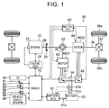
- FIG. 1 is a configuration diagram that shows a schematic configuration of a hybrid vehicle 20 as the embodiment of the present disclosure.
- the hybrid vehicle 20 of the embodiment includes an thermal engine 22, a planetary gear 30, electric motors MG1, MG2, inverters 41, 42, a battery 50, and a hybrid electronic control unit (hereinafter referred to as an "HVECU”) 70.
- HVECU hybrid electronic control unit
- the thermal engine 22 is configured as an internal combustion thermal engine that outputs power by using gasoline, diesel oil, or the like as fuel. An operation of this thermal engine 22 is controlled by an thermal engine electronic control unit (hereinafter referred to as an "thermal engine ECU") 24.
- an thermal engine ECU thermal engine electronic control unit
- the thermal engine ECU 24 is configured as a microprocessor that has a CPU as a central component, and includes, in addition to the CPU, a ROM that stores a processing program, a RAM that temporarily stores data, input/output ports, and a communication port.
- the thermal engine ECU 24 receives signals from various sensors that are required for operation control of the thermal engine 22 via the input port. The following can be raised as the signals received by the thermal engine ECU 24: • A crank angle ⁇ cr from a crank position sensor 23 that detects a rotational position of a crankshaft 26 of the thermal engine 22 • A throttle opening degree TH from a throttle valve position sensor that detects a position of a throttle valve
- the thermal engine ECU 24 outputs various control signals for the operation control of the thermal engine 22 via the output port.
- the following can be raised as the control signals output from the thermal engine ECU 24: • A control signal transmitted to a throttle motor that adjusts the position of the throttle valve • A control signal transmitted to a fuel injection valve • A control signal transmitted to an ignition coil that is integrated with an igniter
- the thermal engine ECU 24 is connected to the HVECU 70 via the communication port, controls the operation of the thermal engine 22 by a control signal from the HVECU 70, and, when necessary, outputs data on an operation state of the thermal engine 22 to the HVECU 70.
- the thermal engine ECU 24 computes a rotational speed of the crankshaft 26, that is, a speed Ne of the thermal engine 22 on the basis of the crank angle ⁇ cr from the crank position sensor 23.
- the planetary gear 30 is configured as a planetary gear mechanism of a single pinion type.
- a rotor of the electric motor MG1 is connected to a sun gear of the planetary gear 30.
- a drive shaft 36 which is coupled to drive wheels 38a, 38b via a differential gear 37, is connected to a ring gear of the planetary gear 30.
- the crankshaft 26 of the thermal engine 22 is connected to a carrier of the planetary gear 30 via a damper 28.
- the electric motor MG1 is configured as a synchronous generator motor, for example, and the rotor thereof is connected to the sun gear of the planetary gear 30 as described above.
- the electric motor MG2 is configured as a synchronous generator motor, for example, and a rotor thereof is connected to the drive shaft 36.
- the inverters 41, 42 are each connected to the battery 50 via an electricity line 54.
- An electric motor electronic control unit (hereinafter referred to as an "electric motor ECU") 40 executes switching control of plural unillustrated switching elements of the inverters 41, 42, and, in this way, the electric motors MG1, MG2 are rotationally driven.
- the electric motor ECU 40 is configured as a microprocessor that has a CPU as a central component, and includes, in addition to the CPU, a ROM that stores a processing program, a RAM that temporarily stores data, input/output ports, and a communication port.
- the electric motor ECU 40 receives signals from various sensors that are required for drive control of the electric motors MG1, MG2 via the input port.
- the electric motor ECU 40 outputs switching control signals, which are transmitted to the plural unillustrated switching elements of the inverters 41, 42, and the like via the output port.
- the electric motor ECU 40 is connected to the HVECU 70 via the communication port, executes the drive control of the electric motors MG1, MG2 by a control signal from the HVECU 70, and, upon necessary, outputs data on drive states of the electric motors MG1, MG2 to the HVECU 70.
- the electric motor ECU 40 computes rotational speeds Nml, Nm2 of the electric motors MG1, MG2 on the basis of the rotational positions ⁇ m1, ⁇ m2 of the rotors of the electric motors MG1, MG2 from the rotational position detection sensors 43, 44.
- the battery 50 is configured as a lithium-ion secondary battery. As described above, this battery 50 is connected to each of the inverters 41, 42 via the electricity line 54.
- the battery 50 is managed by a battery electronic control unit (hereinafter referred to as a "battery ECU") 52.
- battery ECU battery electronic control unit
- the battery ECU 52 is configured as a microprocessor that has a CPU as a central component, and includes, in addition to the CPU, a ROM that stores a processing program, a RAM that temporarily stores data, inpudoutput ports, and a communication port.
- the battery ECU 52 receives signals from various sensors that are required to manage the battery 50 via the input port. The following can be raised as the signals received by the battery ECU 52: • A battery voltage Vb from a voltage sensor 51a that is installed between terminals of the battery 50 • A battery current Ib from a current sensor 51b that is attached to the output terminal of the battery 50 (having a positive value when being discharged from the battery 50) • A battery temperature Tb from a temperature sensor 51c that is attached to the battery 50
- the battery ECU 52 is connected to the HVECU 70 via the communication port and, when necessary, outputs data on a state of the battery 50 to the HVECU 70.
- the battery ECU 52 computes an electric state-of-charge ratio SOC on the basis of an integrated value of the battery current Ib from the current sensor 51b.
- the electric state-of-charge ratio SOC is a ratio of a stored electric energy that can be discharged from the battery 50 to a total electric energy storage capacity of the battery 50.
- the battery ECU 52 also computes an input limit Win and an output limit Wout of the battery 50.
- the input limit Win is a permissible electric power that may be charged to the battery 50
- the output limit Wout is a permissible electric power that may be discharged from the battery 50.
- the HVECU 70 is configured as a microprocessor that has a CPU as a central component, and includes, in addition to the CPU, a ROM that stores a processing program, a RAM that temporarily stores data, input/output ports, and a communication port.
- the HVECU 70 receives signals from various sensors via the input port.
- the HVECU 70 is connected to the thermal engine ECU 24, the electric motor ECU 40, and the battery ECU 52 via the communication ports and transmits/receives the various control signals and data to/from the thermal engine ECU 24, the electric motor ECU 40, and the battery ECU 52.
- a parking position used during parking (a P position), a reverse position for a reverse travel (an R position), a neutral position (an N position), a drive position for a forward travel (a D position), a brake position at which a larger braking force than that at the D position is applied to the vehicle when the accelerator is off (a B position), and the like are prepared in the hybrid vehicle 20 of the embodiment.
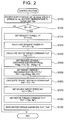
- FIG. 2 is a flowchart of one example of a control routine that is repeatedly executed by the HVECU 70 of the embodiment when the accelerator is off.
- the HVECU 70 first receives the data that includes the shift position SP, the vehicle speed V, a rotational speed Nr of the drive shaft 36, the speed Ne of the thermal engine 22, the battery temperature Tb, the input limit Win of the battery 50, and the like (step S100).
- the shift position SP a value that is detected by the shift position sensor 82 is received.
- the vehicle speed V a value that is detected by the vehicle speed sensor 88 is received.
- the rotational speed Nr of the drive shaft 36 the rotational speed Nm2 of the electric motor MG2 that is computed by the electric motor ECU 40 is received through the communication.
- the input limit Win is set to be increased (its absolute value decreased) in correspondence to a decreased battery temperature Tb, and to be increased (its absolute value decreased) in correspondence to an increased electric state-of-charge ratio SOC. More specifically, the input limit Win is set to be increased in correspondence to a decreased battery temperature Tb, and to be increased in correspondence to an increased electric state-of-charge ratio SOC. This is due to a temperature characteristic and an electric state-of-charge ratio characteristic of the battery 50.
- FIG. 3 is an explanatory chart that shows one example of this relationship.
- a solid line, a broken line, and a one-dot chain line respectively show states of the input limit Win in the case where the charge/discharge electric power Pb at a time when the battery temperature Tb is a uniform temperature and the battery 50 starts being charged is electric power Pb1, Pb2, and Pb3 (Pb3 ⁇ Pb2 ⁇ Pb ⁇ 0).
- the input limit Win is set such that a time period from beginning of charging of the battery 50 to beginning of a rapid increase in the charge/discharge electric power Pb (a rapid decrease of its absolute value) is shortened and that an increase amount per unit time (a decrease amount of its absolute value) at the beginning of the rapid increase in the electric charging/discharging power Pb is increased in comparison with a case where the electric charging/discharging power Pb is high.
- the "rapid increase (rapid decrease)” means that the increase amount (the decrease amount) per unit time is larger than a specified increase amount (a specified decrease amount).
- FIG. 4 is an explanatory chart that shows one example of this relationship.
- a solid line, a broken line, a one-dot chain line, and a two-dot chain line respectively show states of the input limit Win in the cases where the charge/discharge electric power Pb at the time when the battery 50 starts being charged is uniform electric power Pb4 (Pb4 ⁇ 0) and the battery temperatures Tb are temperatures Tb1, Tb2, Tb3, Tb4 (Tb1 > Tb2 > Tb3 > Tb4).
- Pb4 ⁇ 0 the battery temperatures Tb are temperatures Tb1, Tb2, Tb3, Tb4 (Tb1 > Tb2 > Tb3 > Tb4).
- electric power that is obtained by limiting the electric power Pb4 by the input limit Win corresponds to the electric charging/discharging power Pb in this chart.
- the input limit Win is set such that the time period from the beginning of the charging of the battery 50 to the beginning of the rapid increase in the electric charging/discharging power Pb (the rapid decrease of its absolute value) is shortened as the battery temperature Tb is decreased. This is conducted to suppress the precipitation of lithium from the battery 50 and the like and to prevent increased deterioration of the battery 50 in accordance with the battery temperature Tb at the time when the battery 50 is continuously charged.
- step S105 it is determined whether the shift position SP is the B position. If the shift position SP is the B position, the requested torque Tr* that is requested to the vehicle is set on the basis of the vehicle speed V (step S110).
- a relationship between the vehicle speed V and the requested torque Tr* is defined in advance and stored as a request torque setting map in the ROM, which is not shown. Then, when the vehicle speed V is provided, the requested torque Tr* is set by deriving the corresponding requested torque Tr* from this map. Because a situation where the accelerator is turned off and the braking force is applied to the vehicle is considered at this time, a negative value (a value on a braking side) is set for the requested torque Tr*.
- the requested torque Tr* is set to be lower (its absolute value higher) at a time when the shift position SP is the B position and the accelerator is off than that at a time when the shift position SP is the D position and the accelerator is off, and set to be decreased in correspondence to an increased vehicle speed V.
- requested power Pr* that is requested to the vehicle is calculated by multiplying the requested torque Tr* by the rotational speed Nr of the drive shaft 36 (step S120), and the requested torque Tr* is set in a torque command Tm2* of the electric motor MG2 (step S130). Because a forward travel situation (a situation where the rotational speed Nr of the drive shaft 36 is positive) is considered at this time, the requested power Pr* also has a negative value, analogously to the requested torque Tr*.
- requested electric charging/discharging power Pbtag of the battery 50 is set to fall within a range below the value 0 (a range within which the battery 50 is charged) on the basis of the battery temperature Tb and the vehicle speed V (step S140), and a target electric charging/discharging power Pb* of the battery 50 is set by limiting the thus-set requested electric charging/discharging power Pbtag by the input limit Win and the requested power Pr* (being subjected to the lower limit guard) (step S150).
- a relationship among the battery temperature Tb, the vehicle speed V, and the requested electric charging/discharging power Pbtag is defined in advance and stored as a requested electric charging/discharging power setting map in the ROM, which is not shown.
- the requested electric charging/discharging power Pbtag is set by deriving the corresponding requested electric charging/discharging power Pbtag from this map.
- One example of the requested electric charging/discharging power setting map is shown in FIG. 5 .
- a specified negative electric power Pbtag1 is set for the requested electric charging/discharging power Pbtag regardless of the battery temperature Tb and the vehicle speed V.
- the requested electric charging/discharging power Pbtag is set to be increased (its absolute value decreased) in correspondence to a decreased battery temperature Tb, and to be increased (its absolute value decreased) in correspondence to a vehicle speed V ,within a range below the value 0 and above the specified electric power Pbtag1, and, more specifically, is set to be increased in correspondence to a decreased battery temperature Tb and to be increased in correspondence to an increased vehicle speed V.
- the threshold Tbref is an upper limit of a range of the battery temperature Tb within which the time period from the beginning of the charging of the battery 50 to the beginning of the rapid increase (the rapid decrease in terms of absolute value) in the electric charging/discharging power Pb is predicted to be within a specified time period tref (see FIG. 4 , from several tens of seconds to approximately one minute or the like, for example) when the accelerator is off with the shift position SP being the B position, and, for example, 20°C, 22°C, 25°C, or the like can be used therefor.
- the target electric charging/discharging power Pb* of the battery 50 is set as described above, a value that is obtained by subtracting the requested power Pr* from the thus-set target electric charging/discharging power Pb* is set as target motoring power Pmt* (step S160), and a target speed Ne* of the thermal engine 22 is set on the basis of the set target motoring power Pmt* (step S170).
- the target motoring power Pmt* is a target value for the consumed power (consumed electric power) at a time when motoring of the thermal engine 22, which is in a state where fuel injection is stopped, is performed by the electric motor MG1.
- a relationship between the target motoring power Pmt* and the target speed Ne* of the thermal engine 22 is defined in advance and stored as a target speed setting map. Then, when the target motoring power Pmt* is received, the target speed Ne* of the thermal engine 22 is set by deriving the corresponding target speed Ne* from this map.
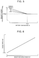
- the target speed setting map is shown in FIG. 6 .
- the target speed Ne* of the thermal engine 22 is set to be increased in correspondence to an increased target motoring power Pmt*. This is because friction of the thermal engine 22 is increased and the consumed electric power by the electric motor MG1 is increased in correspondence to an increased speed Ne of the thermal engine 22.
- the requested power Pr* is set to be lower (its absolute value higher) than the requested electric charging/discharging power Pbtag regardless of the battery temperature Tb.
- the target motoring power Pmt* and the target speed Ne* of the thermal engine 22 each obtain a value that is higher than the value 0.
- the time period from the beginning of the charging of the battery 50 to the beginning of the rapid increase (the rapid decrease in terms of absolute value) in the electric charging/discharging power Pb of the battery 50 basically corresponds to a time period in which the requested electric charging/discharging power Pbtag is set as the target electric charging/discharging power Pb*.
- the specified negative electric power Pbtag1 is set as the requested electric charging/discharging power Pbtag regardless of the battery temperature Tb and the vehicle speed V.
- the requested electric charging/discharging power Pbtag is set to be increased (its absolute value decreased) in correspondence to a decreased battery temperature Tb, and to be increased (its absolute value decreased) in correspondence to an increased vehicle speed V, within a range below the value 0 and above the specified electric power Pbtag1. Accordingly, when the battery temperature Tb is at least equal to the threshold Tbref, the target motoring power Pmt* becomes constant, and the target speed Ne* of the thermal engine 22 becomes constant regardless of the battery temperature Tb and the vehicle speed V.
- the target motoring power Pmt* and the target speed Ne* of the thermal engine 22 become higher than those at the time when the battery temperature Tb is at least equal to the threshold Tbref. Furthermore, at this time, the target electric motoring power Pmt* and the target speed Ne* of the thermal engine 22 are increased in correspondence to a decreased battery temperature Tb. In addition, the target motoring power Pmt* and the target speed Ne* of the thermal engine 22 are increased in correspondence to an increased vehicle speed V.
- a situation where the input limit Win of the battery 50 is set as the target electric charging/discharging power Pb* and the requested power Pr* is constant is considered.
- a time period after the beginning of the rapid increase (the rapid decrease in terms of absolute value) in the electric charging/discharging power Pb of the battery 50 basically corresponds to a time period in which the input limit Win is set as the target electric charging/discharging power Pb*.
- the target motoring power Pmt* and the target speed Ne* of the thermal engine 22 are set in accordance with the input limit Win. Accordingly, the target speed Ne* of the thermal engine 22 is increased in correspondence to an increased input limit Win (decreased absolute value of the input limit Win).
- a torque command Tm1* of the electric motor MG1 is set by the following expression (1) using the speed Ne and the target speed Ne* of the thermal engine 22 (step S180).
- the expression (1) is a relational expression in speed feedback control for rotating the thermal engine 22 at the target speed Ne*.
- "k1" in the first term on a right side refers to a gain of a proportional term
- "k2" in the second term on the right side refers to a gain of an integration term.
- Tm 1 * k 1 • Ne * ⁇ Ne + k 2 • ⁇ Ne * ⁇ Ne dt
- step S190 when the torque commands Tm1*, Tm2* of the electric motors MG1, MG2 are set, the set torque commands Tm1*, Tm2* are sent to the electric motor ECU 40 (step S190), and this routine is terminated.
- the electric motor ECU 40 executes the switching control of the switching elements of the inverters 41, 42 such that the electric motors MG1, MG2 are respectively driven by the torque commands Tm1*, Tm2*.
- the braking force can be applied to the vehicle while the battery 50 is charged within the range limited by the input limit Win of the battery 50 by regenerative drive of the electric motor MG2 and motoring of the thermal engine 22, which is in the state where fuel injection is stopped, by the electric motor MG1.
- torque applied to the drive shaft 36 corresponds to a sum of torque applied to the drive shaft 36 by the regenerative drive of the electric motor MG2 and torque applied to the drive shaft 36 by motoring of the thermal engine 22 by the electric motor MG1.
- the latter torque is basically much lower than the former torque (for example, approximately one tenth to one twentieth thereof), the request torque Tr* is set in the torque command Tm2* in the embodiment.
- the requested electric charging/discharging power Pbtag becomes higher (its absolute value lower) than that at the time when the battery temperature Tb is at least equal to the threshold Tbref, so as to increase the target electric charging/discharging power Pb*, the target motoring power Pmt*, and the target speed Ne* of the thermal engine 22 in the time period from the beginning of the charging of the battery 50 to the beginning of the rapid increase (the rapid decrease in terms of absolute value) in the electric charging/discharging power Pb of the battery 50.
- the consumed electric power by the electric motor MG1 until the beginning of the rapid increase in the electric charging/discharging power Pb of the battery 50 is increased, and the electric charging/discharging power Pb of the battery 50 is increased (its absolute value decreased).
- the input limit Win is set such that the time period from the beginning of the charging of the battery 50 to the beginning of the rapid increase (the rapid decrease in terms of absolute value) in the electric charging/discharging power Pb is shortened and the increase amount (the decrease amount in terms of absolute value) per unit time at the beginning of the rapid increase in the electric charging/discharging power Pb is increased when the electric charging/discharging power Pb is low (its absolute value high) in comparison with the case where the electric power Pb is high.
- the following effects can be exerted by increasing the electric charging/discharging power Pb of the battery 50 (decreasing its absolute value) until the beginning of the rapid increase in the electric charging/discharging power Pb of the battery 50 when the battery temperature Tb is lower than the threshold Tbref.
- the requested electric charging/discharging power Pbtag is set to be increased (its absolute value decreased) in correspondence to a decreased battery temperature Tb and to be increased (its absolute value decreased) in correspondence to an increased vehicle speed V when the battery temperature Tb is lower than the threshold Tbref.
- the input limit Win is set such that the time period from the beginning of the charging of the battery 50 to the beginning of the rapid increase (the rapid decrease in terms of absolute value) in the electric charging/discharging power Pb is shortened in correspondence to a decreased the battery temperature Tb. Accordingly, as shown in FIG.
- the requested electric charging/discharging power Pbtag is set to be increased (its absolute value decreased) in correspondence to an increased vehicle speed V.
- the target electric charging/discharging power Pb*, the target motoring power Pmt*, and the target speed Ne* of the thermal engine 22 are increased.
- the target speed Ne* (the speed Ne) of the thermal engine 22 is decreased along with a decrease in the vehicle speed V when the accelerator remains off.
- the driver can perceive a feeling of deceleration.
- step S105 this routine is terminated as is.
- the request torque Tr* is higher (its absolute value lower) and the requested power Pr* is higher (its absolute value lower) than those at the time when the accelerator is off with the shift position SP being the B position.
- a value in such a magnitude that the time period from the beginning of the charging of the battery 50 to the beginning of the rapid increase (the rapid decrease in terms of absolute value) in the electric charging/discharging power Pb is not predicted to be within the specified time period tref even at the time when the battery temperature Tb is lower than the threshold Tbref is set for the requested torque Tr* (the requested power Pr*).
- the braking force is applied to the vehicle while the battery 50 is charged by the regenerative drive of the electric motor MG2 with the electric power that corresponds to the requested power Pr*.
- FIG. 7 is an explanatory chart that shows one example of states of temporal changes in the electric charging/discharging power Pb and the input limit Win of the battery 50 and the speed Ne of the thermal engine 22 at the time when the accelerator is off with the shift position SP being the B position and the battery temperature Tb is lower than the threshold Tbref.
- solid lines indicate the state in the embodiment, and broken lines indicate a state in a comparative example.
- the target speeds Ne* (the speeds Ne) of the thermal engine 22 at these times are set to be the same.
- the speed Ne of the thermal engine 22 at the time when the battery 50 starts being charged is increased to be higher than that at the time when the battery temperature Tb is at least equal to the threshold Tbref, so as to increase (decrease in terms of absolute value) the electric charging/discharging power Pb from the beginning of the charging of the battery 50 to the beginning of the rapid increase (the rapid decrease in terms of absolute value) in the electric charging/discharging power Pb of the battery 50.
- the braking force is applied to the vehicle while the battery 50 is charged within the range limited by the input limit Win of the battery 50 by the regenerative drive of the electric motor MG2 and motoring of the thermal engine 22, which is in the state where the fuel injection is stopped, by the electric motor MG1.
- the request electric charging/discharging power Pbtag is increased (its absolute value decreased) to be higher than that at the time when the battery temperature Tb is at least equal to the threshold Tbref, so as to increase the target electric charging/discharging power Pb*, the target motoring power Pmt*, and the target speed Ne* (the speed Ne) of the thermal engine 22 from the beginning of the charging of the battery 50 to the beginning of the rapid increase (the rapid decrease in terms of absolute value) in the electric charging/discharging power Pb of the battery 50.
- the consumed electric power by the electric motor MG1 until the beginning of the rapid increase in the electric charging/discharging power Pb of the battery 50 is increased, so as to increase (decrease in terms of absolute value) the electric charging/discharging power Pb of the battery 50. Accordingly, it is possible to prevent shortening of the time period until the beginning of the rapid increase (the rapid decrease in terms of absolute value) in the electric charging/discharging power Pb of the battery 50, and is possible to prevent shortening of the time period until the beginning of the rapid increase in the speed Ne of the thermal engine 22.
- the requested electric charging/discharging power Pbtag of the battery 50 is set in accordance with the battery temperature Tb and the vehicle speed V so as to become lower than the value 0 and to fall within the range that is higher than the range if the battery temperature Tb is at least equal to the threshold Tbref.
- the requested electric charging/discharging power Pbtag of the battery 50 may be set in accordance with either the battery temperature Tb or the vehicle speed V, or a uniform value may be used therefor regardless of the battery temperature Tb and the vehicle speed V, as long as the requested electric charging/discharging power Pbtag of the battery 50 is set to become lower than the value 0 and to fall within the range that is higher than the range at the time when the battery temperature Tb is at least equal to the threshold Tbref.
- the requested electric charging/discharging power Pbtag is increased (decreased in terms of absolute value) to be higher than that if the battery temperature Tb is at least equal to the threshold Tbref, so as to increase the target electric charging/discharging power Pb*, the target motoring power Pmt*, and the target speed Ne* of the thermal engine 22 from the beginning of the charging of the battery 50 to the beginning of the rapid increase (the rapid decrease in terms of absolute value) in the electric charging/discharging power Pb of the battery 50.
- the requested electric charging/discharging power Pbtag may not be set, but the target speed Ne* of the thermal engine 22 may directly be set such that the target speed Ne* of the thermal engine 22 becomes higher than that if the battery temperature Tb is at least equal to the threshold Tbref and that the electric charging/discharging power Pb of the battery 50 falls within the range of the input limit Win.
- a relationship among the requested torque Tr*, the battery temperature Tb, and the target speed Ne* of the thermal engine 22 is defined in advance and stored as a target speed setting map of a modified example in the ROM, which is not shown.
- the target speed Ne* of the thermal engine 22 from the beginning of the charging of the battery 50 to the beginning of the rapid increase (the rapid decrease in terms of absolute value) in the electric charging/discharging power Pb of the battery 50 can be set by deriving the corresponding target speed Ne* from this map when the request torque Tr* and the battery temperature Tb are received.
- FIG. 8 One example of the target speed setting map of the modified example is shown in FIG. 8 .
- the target speed Ne* of the thermal engine 22 when the battery temperature Tb is at least equal to the threshold Tbref and the request torque Tr* is low (its absolute value high), the target speed Ne* of the thermal engine 22 can be set to be higher than that if the requested torque Tr* is high. More specifically, the target speed Ne* of the thermal engine 22 can be set to be increased in correspondence to a decreased request torque Tr*. In addition, when the battery temperature Tb is lower than the threshold Tbref and the request torque Tr* is low (its absolute value high), the target speed Ne* of the thermal engine 22 can be set to be higher than that if the requested torque Tr* is high and to be increased in correspondence to a decreased battery temperature Tb.
- the target speed Ne* of the thermal engine 22 can be set to be increased in correspondence to a decreased request torque Tr* and to be increased in correspondence to a decreased battery temperature Tb.
- the target speed Ne* of the thermal engine 22 at the beginning of the rapid increase (the rapid decrease in terms of absolute value) in the electric charging/discharging power Pb of the battery 50 onward can be set such that the electric charging/discharging power Pb of the battery 50 falls within the range limited by the input limit Win, more specifically, the electric charging/discharging power Pb of the battery 50 is increased along with a rapid increase (a rapid decrease in terms of absolute value) in the input limit Win.
- the requested power Pr* is lower (its absolute value higher) than the request electric charging/discharging power Pbtag regardless of the battery temperature Tb when the accelerator is off with the shift position SP being the B position.
- the motoring of the thermal engine 22 is performed by the electric motor MG1 from the beginning of the charging of the battery 50 to the beginning of the rapid increase (the rapid decrease in terms of absolute value) in the electric charging/discharging power Pb of the battery 50 regardless of the battery temperature Tb, that is, regardless of whether the time period from the beginning of the charging of the battery 50 to the beginning of the rapid increase (the rapid decrease in terms of absolute value) in the electric charging/discharging power Pb (a pre rapid increase time period) is predicted to be within the specified time period tref.
- the requested power Pr* may become at least equal to the requested electric charging/discharging power Pbtag.
- the motoring of the thermal engine 22 may not be performed by the electric motor MG1.
- the requested electric charging/discharging power Pbtag is increased (decreased in terms of absolute value) to be higher than that if the battery temperature Tb is at least equal to the threshold Tbref, so as to increase the target electric charging/discharging power Pb*, the target motoring power Pmt*, and the target speed Ne* of the thermal engine 22 from the beginning of the charging of the battery 50 to the beginning of the rapid increase (the rapid decrease in terms of absolute value) in the electric charging/discharging power Pb of the battery 50.
- similar control may be executed when the accelerator is off with the shift position SP being the D position.
- the battery 50 is configured as the lithium-ion secondary battery.
- the battery 50 may be configured as a nickel hydrogen secondary battery or the like.
- the thermal engine 22 is one example of the "thermal engine”
- the electric motor MG1 is one example of the “first electric motor”
- the planetary gear 30 is one example of the “planetary gear”
- the electric motor MG2 is one example of the “second electric motor”
- the battery 50 is one example of the "battery”
- the HVECU 70, the thermal engine ECU 24, and the electric motor ECU 40 are one example of the "electronic control unit”.
- the embodiment will be summarized.
- the braking force is applied to the vehicle while the battery is charged within the range limited by the input limit Win of the battery by the regenerative drive of the second electric motor and motoring of the thermal engine, which is in the state where the fuel injection is stopped, by the first electric motor.
- the request electric charging/discharging power Pbtag is increased (decreased in terms of absolute value) to be higher than that at the time when the battery temperature Tb is at least equal to the threshold Tbref (S 140), so as to increase the target electric charging/discharging power Pb*, the target motoring power Pmt*, and the target speed Ne* of the thermal engine (S150 to S170).
- the present disclosure is not limited to the above embodiment in any respect and, needless to say, can be implemented in various modes within a range that does not depart from the gist of the present disclosure.
- the present disclosure can be used in a manufacturing industry of hybrid vehicles, and the like.
Abstract
Description
- The present disclosure relates to a hybrid vehicle.
- Conventionally, for example,
Japanese Patent Application Publication No. 2014-125078 JP 2014-125078 A - In general, deterioration of the battery is likely to be promoted when the battery is continuously charged with relatively high electric charging power (charge current). Accordingly, in order to prevent an increased deterioration of the battery, when the battery is continuously charged, a permissible electric charging power to the battery is set such that a time period from beginning of the charging to beginning of a rapid decrease in the charged electricity is shortened and a decrease amount per unit time (a decreased rate) at the beginning of the rapid decrease in the electric charging power is increased in correspondence to an increased electric charging power to the battery. When the electric charging power starts being rapidly decreased, an thermal engine speed has to be rapidly increased, and consumed electricity by the first electric motor has to be rapidly increased. However, when an increase amount in the thermal engine speed per unit time is relatively large, a driver possibly receives a sense of discomfort.
- A hybrid vehicle and control method of the present disclosure can suppress a driver from receiving a sense of discomfort when an accelerator remains off.
- A hybrid vehicle of the present disclosure is a hybrid vehicle that includes: an thermal engine; a first electric motor; a planetary gear, three rotational elements of which are respectively connected to a rotational shaft of the first electric motor, an output shaft of the thermal engine, and a drive shaft coupled to an axle, the three rotational elements being connected such that the rotational shaft, the output shaft, and the drive shaft are aligned in this order in a collinear diagram; a second electric motor connected to the drive shaft; a battery for supplying/receiving electric power to/from the first electric motor and the second electric motor; setting means for setting permissible electric charging power and permissible discharge electricity of the battery; and an electronic control unit for controlling the thermal engine, the first electric motor, and the second electric motor such that the vehicle travels while the battery is charged/discharged within ranges limited by the permissible electric charging power and permissible electric discharging power , and is summarized that the setting means sets the permissible electric charging power such that a time period from beginning of the charging to beginning of a rapid decrease in electric charging power is shortened and a decrease amount per unit time at the beginning of the rapid decrease in the electric charging power is increased in correspondence to an increased electric charging power to the battery when the battery is continuously charged, and that, in the case where acceleration off control for controlling the first electric motor and the second electric motor such that the battery is charged within the range limited by the permissible electric charging power range at least in conjunction with regenerative drive of the second electric motor in a state where fuel injection of the thermal engine is stopped and a braking force corresponding to acceleration off is applied to the vehicle is executed during the acceleration off, the electronic control unit controls the first electric motor such that the thermal engine is motored at a first speed by the first electric motor or the motoring of the thermal engine is not performed by the first electric motor when a predictable condition, under which the time period from the beginning of the charging to the beginning of the rapid decrease in the electric charging power is predicted to fall within a specified time period, is not satisfied in the time period from the beginning of the charging to the beginning of the rapid decrease in the electric charging power, and the electronic control unit controls the first electric motor such that the motoring of the thermal engine is performed by the first electric motor at a second speed that is higher than the first speed, and controls the first electric motor such that the motoring of the thermal engine is performed by the first electric motor at a speed at which the electric charging power falls within the permissible electric charging power range from the beginning of the rapid decrease in the electric charging power onward when the predictable condition is satisfied.
- In the hybrid vehicle and control method of this disclosure, the thermal engine, the first electric motor, and the second electric motor are controlled such that the vehicle travels while the battery is charged/discharged within the permissible electric charging power and permissible electric discharging power ranges. Then, when the battery is continuously charged, the permissible electric charging power is set such that the time period from the beginning of the charging to the beginning of the rapid decrease in the electric charging power is shortened and the decrease amount per unit time at the beginning of the rapid decrease in the electric charging power is increased in correspondence to an increase in the electric charging power to the battery. Here, the "rapid decrease" means that the decrease amount per unit time is larger than a specified decrease amount. In addition, when the acceleration off control for controlling the first electric motor and the second electric motor such that the battery is charged within the permissible electric charging power range at least in conjunction with the regenerative drive of the second electric motor in the state where the fuel injection of the thermal engine is stopped and that the braking force corresponding to the acceleration off is applied to the vehicle is executed during the acceleration off, the following control is executed. When the predictable condition, under which the time period from the beginning of the charging to the beginning of the rapid decrease in the electric charging power is predicted to fall within the specified time period, is not satisfied in the time period from the beginning of the charging to the beginning of the rapid decrease in the electric charging power, the first electric motor is controlled such that the motoring of the thermal engine is performed at the first speed by the first electric motor, or the motoring of the thermal engine is not performed by the first electric motor. Alternatively, when the predictable condition is satisfied in the time period from the beginning of the charging to the beginning of the rapid decrease in the electric charging power, the first electric motor is controlled such that the motoring of the thermal engine is performed at the second speed that is higher than the first speed by the first electric motor. From the beginning of the rapid decrease in the electric charging power onward, the first electric motor is controlled such that the motoring of the thermal engine is performed by the first electric motor at the speed, at which the electric charging power falls within the range limited by the permissible electric charging power. When the electric charging power starts being rapidly decreased, the thermal engine speed starts being rapidly increased. In the hybrid vehicle of the present disclosure, if the predictable condition is satisfied, the thermal engine speed is increased to be higher than the thermal engine speed if the predictable condition is not satisfied in the time period from the beginning of the charging to the beginning of the rapid decrease in the electric charging power. In this way, compared to a vehicle in which the thermal engine speed is set to be the same whether the predictable condition is satisfied or not (set at a
value 0 or the first speed), the electric power consumed by the first electric motor is increased, and the electric charging power to the battery is decreased if the predictable condition is satisfied. Accordingly, it is possible to prevent shortening of a time period until the beginning of the rapid decrease in the electric charging power to the battery and to prevent shortening of a time period until beginning of a rapid increase in the thermal engine speed. In addition, it is possible to prevent an increase in the decrease amount per unit time at the beginning of the rapid decrease in the electric charging power to the battery and to prevent an increase in an increase amount per unit time upon the rapid increase in the thermal engine speed. Consequently, the driver is less likely to perceive a sense of discomfort when the accelerator remains off. - In such a hybrid vehicle of the present disclosure, the setting means may set the permissible electric charging power such that the time period from the beginning of the charging to the beginning of the rapid decrease in the electric charging power is shortened in correspondence to a decreased temperature of the battery when the charging is continued, and the predictable condition may be that the temperature of the battery is lower than a specified temperature. In this way, the driver is less likely to perceive the sense of discomfort when the temperature of the battery is lower than the specified temperature and the accelerator remains off.
- In the hybrid vehicle of the present disclosure in an aspect in which the permissible electric charging power is set such that the time period from the beginning of the charging to the beginning of the rapid decrease in the electric charging power is shortened in correspondence to a decreased temperature of the battery when the battery is continuously charged, the electronic control unit may control the thermal engine such that the speed at which the thermal engine is motored is increased in correspondence to a decreased temperature of the battery under the predictable condition until the beginning of the rapid decrease in the electric charging power when the acceleration off control is executed. In this way, it is possible to further appropriately prevent that the driver perceives a sense of discomfort in accordance with the temperature of the battery when the temperature of the battery is lower than the specified temperature and the accelerator remains off.
- In the hybrid vehicle of the present disclosure, the electronic control unit may control the thermal engine such that the motoring of the thermal engine is performed at the higher speed as a vehicle speed is increased under the predictable condition until the beginning of the rapid decrease in the electric charging power when the acceleration off control is executed. In this way, the thermal engine speed is decreased along with a decrease in the vehicle speed. Thus, the driver can receive a feeling of deceleration.
- In the hybrid vehicle of the present disclosure in the aspect in which the permissible electric charging power is set such that the time period from the beginning of the charging to the beginning of the rapid decrease in the electric charging power is shortened in correspondence to a decreased temperature of the battery when the battery is continuously charged, the electronic control unit may set a requested electric charging power of the battery to be decreased in correspondence to a decreased temperature of the battery and to be decreased in correspondence to an increased vehicle speed under the predictable condition until the beginning of the rapid decrease in the electric charging power when the acceleration off control is executed, may set target electric charging power of the battery by limiting the requested electric charging power by the permissible electric charging power, and may set a target speed of the thermal engine to be increased in correspondence to a decreased target electric charging power is decreased, so as to control the thermal engine such that the motoring of the thermal engine is performed at the target speed. In this way, by setting the request electric charging power in accordance with the temperature of the battery and the vehicle speed under the predictable condition and setting the target electric charging power and the target speed in accordance with this, the driver will less likely to receive the sense of discomfort when the accelerator remains off.
- In the hybrid vehicle of the present disclosure, the hybrid vehicle may include, as shift positions, a first travel position and a second travel position at which a larger braking force than that at the first travel position is applied to the vehicle during the acceleration off, and the electronic control unit may control the thermal engine such that the motoring of the thermal engine is performed at a speed that corresponds to whether the predictable condition is satisfied until the beginning of the rapid decrease in the electric charging power when the accelerator is off with the shift position being the second travel position and the acceleration off control is executed. Here, it may be set that the first travel position is a drive position (a D position) and the second travel position is a brake position (a B position). In this way, when the shift position is the second travel position (the driver performs a shift operation to the second travel position) and the accelerator remains off, the driver will less likely to receive the sense of discomfort.
- Features, advantages, and technical and industrial significance of exemplary embodiments of the invention will be described below with reference to the accompanying drawings, in which like numerals denote like elements, and wherein:
-
FIG. 1 is a configuration diagram that shows a schematic configuration of ahybrid vehicle 20 as an embodiment of the present disclosure; -
FIG. 2 is a flowchart of one example of a control routine that is repeatedly executed by anHVECU 70 of the embodiment when an accelerator is off; -
FIG. 3 is an explanatory chart that shows one example of a relationship between charge/discharge electric power Pb (a charge/discharge current Ib) and an input limit Win at a time when abattery 50 is continuously charged; -
FIG. 4 is an explanatory chart that shows one example of a relationship between a battery temperature Tb and the input limit Win at the time when thebattery 50 is continuously charged; -
FIG. 5 is an explanatory chart that shows one example of a request charge/discharge electricity setting map; -
FIG. 6 is an explanatory chart that shows one example of a target speed setting map; -
FIG. 7 is an explanatory chart that shows one example of states of temporal changes in the charge/discharge electric power Pb and the input limit Win of thebattery 50 and a speed Ne of anthermal engine 22 at a time when the accelerator is off with a shift position SP being a B position and the battery temperature Tb is lower than a threshold Tbref; and -
FIG. 8 is an explanatory chart that shows one example of a target speed setting map. - Next, a description will be made on a mode for carrying out the present disclosure by using an embodiment.
-
FIG. 1 is a configuration diagram that shows a schematic configuration of ahybrid vehicle 20 as the embodiment of the present disclosure. As shown in the drawing, thehybrid vehicle 20 of the embodiment includes anthermal engine 22, aplanetary gear 30, electric motors MG1, MG2,inverters battery 50, and a hybrid electronic control unit (hereinafter referred to as an "HVECU") 70. - The
thermal engine 22 is configured as an internal combustion thermal engine that outputs power by using gasoline, diesel oil, or the like as fuel. An operation of thisthermal engine 22 is controlled by an thermal engine electronic control unit (hereinafter referred to as an "thermal engine ECU") 24. - Although not shown, the thermal engine ECU 24 is configured as a microprocessor that has a CPU as a central component, and includes, in addition to the CPU, a ROM that stores a processing program, a RAM that temporarily stores data, input/output ports, and a communication port. The thermal engine ECU 24 receives signals from various sensors that are required for operation control of the
thermal engine 22 via the input port. The following can be raised as the signals received by the thermal engine ECU 24: • A crank angle θcr from acrank position sensor 23 that detects a rotational position of acrankshaft 26 of thethermal engine 22 • A throttle opening degree TH from a throttle valve position sensor that detects a position of a throttle valve - The
thermal engine ECU 24 outputs various control signals for the operation control of thethermal engine 22 via the output port. The following can be raised as the control signals output from the thermal engine ECU 24: • A control signal transmitted to a throttle motor that adjusts the position of the throttle valve • A control signal transmitted to a fuel injection valve • A control signal transmitted to an ignition coil that is integrated with an igniter - The
thermal engine ECU 24 is connected to theHVECU 70 via the communication port, controls the operation of thethermal engine 22 by a control signal from theHVECU 70, and, when necessary, outputs data on an operation state of thethermal engine 22 to theHVECU 70. Thethermal engine ECU 24 computes a rotational speed of thecrankshaft 26, that is, a speed Ne of thethermal engine 22 on the basis of the crank angle θcr from thecrank position sensor 23. - The
planetary gear 30 is configured as a planetary gear mechanism of a single pinion type. A rotor of the electric motor MG1 is connected to a sun gear of theplanetary gear 30. Adrive shaft 36, which is coupled to drivewheels differential gear 37, is connected to a ring gear of theplanetary gear 30. Thecrankshaft 26 of thethermal engine 22 is connected to a carrier of theplanetary gear 30 via adamper 28. - The electric motor MG1 is configured as a synchronous generator motor, for example, and the rotor thereof is connected to the sun gear of the
planetary gear 30 as described above. The electric motor MG2 is configured as a synchronous generator motor, for example, and a rotor thereof is connected to thedrive shaft 36. Theinverters battery 50 via anelectricity line 54. An electric motor electronic control unit (hereinafter referred to as an "electric motor ECU") 40 executes switching control of plural unillustrated switching elements of theinverters - Although not shown, the
electric motor ECU 40 is configured as a microprocessor that has a CPU as a central component, and includes, in addition to the CPU, a ROM that stores a processing program, a RAM that temporarily stores data, input/output ports, and a communication port. Theelectric motor ECU 40 receives signals from various sensors that are required for drive control of the electric motors MG1, MG2 via the input port. The following can be raised as the signals received by the electric motor ECU 40: • Rotational positions θm1, θm2 from rotationalposition detection sensors - The
electric motor ECU 40 outputs switching control signals, which are transmitted to the plural unillustrated switching elements of theinverters electric motor ECU 40 is connected to theHVECU 70 via the communication port, executes the drive control of the electric motors MG1, MG2 by a control signal from theHVECU 70, and, upon necessary, outputs data on drive states of the electric motors MG1, MG2 to theHVECU 70. Theelectric motor ECU 40 computes rotational speeds Nml, Nm2 of the electric motors MG1, MG2 on the basis of the rotational positions θm1, θm2 of the rotors of the electric motors MG1, MG2 from the rotationalposition detection sensors - The
battery 50 is configured as a lithium-ion secondary battery. As described above, thisbattery 50 is connected to each of theinverters electricity line 54. Thebattery 50 is managed by a battery electronic control unit (hereinafter referred to as a "battery ECU") 52. - Although not shown, the
battery ECU 52 is configured as a microprocessor that has a CPU as a central component, and includes, in addition to the CPU, a ROM that stores a processing program, a RAM that temporarily stores data, inpudoutput ports, and a communication port. Thebattery ECU 52 receives signals from various sensors that are required to manage thebattery 50 via the input port. The following can be raised as the signals received by the battery ECU 52: • A battery voltage Vb from avoltage sensor 51a that is installed between terminals of thebattery 50 • A battery current Ib from acurrent sensor 51b that is attached to the output terminal of the battery 50 (having a positive value when being discharged from the battery 50) • A battery temperature Tb from atemperature sensor 51c that is attached to thebattery 50 - The
battery ECU 52 is connected to theHVECU 70 via the communication port and, when necessary, outputs data on a state of thebattery 50 to theHVECU 70. Thebattery ECU 52 computes an electric state-of-charge ratio SOC on the basis of an integrated value of the battery current Ib from thecurrent sensor 51b. The electric state-of-charge ratio SOC is a ratio of a stored electric energy that can be discharged from thebattery 50 to a total electric energy storage capacity of thebattery 50. Thebattery ECU 52 also computes an input limit Win and an output limit Wout of thebattery 50. The input limit Win is a permissible electric power that may be charged to thebattery 50, and the output limit Wout is a permissible electric power that may be discharged from thebattery 50. - Although not shown, the
HVECU 70 is configured as a microprocessor that has a CPU as a central component, and includes, in addition to the CPU, a ROM that stores a processing program, a RAM that temporarily stores data, input/output ports, and a communication port. TheHVECU 70 receives signals from various sensors via the input port. The following can be raised as the signals received by the HVECU 70: • An ignition signal from anignition switch 80 • A shift position SP from ashift position sensor 82 that detects an operation position of ashift lever 81 • An accelerator pedal operation amount Acc from an acceleratorpedal position sensor 84 that detects a depression amount of anaccelerator pedal 83 • A brake pedal position BP from a brakepedal position sensor 86 that detects a depression amount of abrake pedal 85 • A vehicle speed V from avehicle speed sensor 88 - As described above, the
HVECU 70 is connected to thethermal engine ECU 24, theelectric motor ECU 40, and thebattery ECU 52 via the communication ports and transmits/receives the various control signals and data to/from thethermal engine ECU 24, theelectric motor ECU 40, and thebattery ECU 52. - Note that, as the operation positions of the shift lever 81 (the shift positions SP that are detected by the shift position sensor 82), a parking position used during parking (a P position), a reverse position for a reverse travel (an R position), a neutral position (an N position), a drive position for a forward travel (a D position), a brake position at which a larger braking force than that at the D position is applied to the vehicle when the accelerator is off (a B position), and the like are prepared in the
hybrid vehicle 20 of the embodiment. - In the
hybrid vehicle 20 of the embodiment that is configured as described above, first, a requested torque Tr* that is requested for travel (requested from the drive shaft 36) is set on the basis of the shift position SP, the accelerator pedal operation amount Acc, and the vehicle speed V. Then, thethermal engine 22 and the electric motors MG1, MG2 are controlled such that thethermal engine 22 is operated or stops being operated, that electric charging/discharging power Pb (= Vb • Ib) of thebattery 50 falls within ranges limited by the input and output limits Win, Wout, and that torque based on the requested torque Tr* is output to thedrive shaft 36. - Next, a description will be made on an operation of the
hybrid vehicle 20 of the embodiment that is configured as described above and particularly on an operation thereof at a time when the shift position SP is shifted to the B position, the accelerator is turned off (the accelerator pedal operation amount Acc obtains a value 0), and the braking force is applied to the vehicle during the forward travel.FIG. 2 is a flowchart of one example of a control routine that is repeatedly executed by theHVECU 70 of the embodiment when the accelerator is off. - When the control routine in
FIG. 2 is executed, theHVECU 70 first receives the data that includes the shift position SP, the vehicle speed V, a rotational speed Nr of thedrive shaft 36, the speed Ne of thethermal engine 22, the battery temperature Tb, the input limit Win of thebattery 50, and the like (step S100). Here, as the shift position SP, a value that is detected by theshift position sensor 82 is received. As the vehicle speed V, a value that is detected by thevehicle speed sensor 88 is received. In addition, as the rotational speed Nr of thedrive shaft 36, the rotational speed Nm2 of the electric motor MG2 that is computed by theelectric motor ECU 40 is received through the communication. As the speed Ne of thethermal engine 22, a value that is computed by thethermal engine ECU 24 is received through the communication. As the battery temperature Tb, a value that is detected by thetemperature sensor 51c is received from thebattery ECU 52 through the communication. As the input limit Win of thebattery 50, values that are computed by thebattery ECU 52 are received through the communication. - Here, the input limit Win of the
battery 50 will be described. Thebattery ECU 52 sets the input limit Win of thebattery 50 within a range with an upper limit equal to avalue 0 on the basis of the battery temperature Tb, the electric state-of-charge ratio SOC, and the electric charging/discharging power Pb (= Vb • Ib) at a time when thebattery 50 is continuously charged. - First, a description will be made on a relationship between the input limit Win and each of the battery temperature Tb and the electric state-of-charge ratio SOC. In this relationship, the input limit Win is set to be increased (its absolute value decreased) in correspondence to a decreased battery temperature Tb, and to be increased (its absolute value decreased) in correspondence to an increased electric state-of-charge ratio SOC. More specifically, the input limit Win is set to be increased in correspondence to a decreased battery temperature Tb, and to be increased in correspondence to an increased electric state-of-charge ratio SOC. This is due to a temperature characteristic and an electric state-of-charge ratio characteristic of the
battery 50. - Next, a description will be made on a relationship between the electric charging/discharging power Pb and the input limit Win at the time when the
battery 50 is continuously charged.FIG. 3 is an explanatory chart that shows one example of this relationship. In the chart, a solid line, a broken line, and a one-dot chain line respectively show states of the input limit Win in the case where the charge/discharge electric power Pb at a time when the battery temperature Tb is a uniform temperature and thebattery 50 starts being charged is electric power Pb1, Pb2, and Pb3 (Pb3 < Pb2 < Pb < 0). Note that, in this chart, electric power that is obtained by limiting the electric power Pb1, Pb2, Pb3 by the input limit Win (that is, subjected to a lower limit guard) corresponds to the electric charging/discharging power Pb. In this relationship, as shown inFIG. 3 , when the electric charging/discharging power Pb is low (its absolute value high), the input limit Win is set such that a time period from beginning of charging of thebattery 50 to beginning of a rapid increase in the charge/discharge electric power Pb (a rapid decrease of its absolute value) is shortened and that an increase amount per unit time (a decrease amount of its absolute value) at the beginning of the rapid increase in the electric charging/discharging power Pb is increased in comparison with a case where the electric charging/discharging power Pb is high. This is conducted to suppress precipitation of lithium from thebattery 50 and the like and to suppress deterioration of thebattery 50 from being promoted in accordance with history at the time when thebattery 50 is continuously charged (an integrated value of the electric charging/discharging power Pb (the charge/discharge current Ib)). Note that the "rapid increase (rapid decrease)" means that the increase amount (the decrease amount) per unit time is larger than a specified increase amount (a specified decrease amount). - Furthermore, a description will be made of a relationship between the battery temperature Tb and the input limit Win at the time when the
battery 50 is continuously charged.FIG. 4 is an explanatory chart that shows one example of this relationship. In the chart, a solid line, a broken line, a one-dot chain line, and a two-dot chain line respectively show states of the input limit Win in the cases where the charge/discharge electric power Pb at the time when thebattery 50 starts being charged is uniform electric power Pb4 (Pb4 < 0) and the battery temperatures Tb are temperatures Tb1, Tb2, Tb3, Tb4 (Tb1 > Tb2 > Tb3 > Tb4). Note that, similar toFIG. 3 , electric power that is obtained by limiting the electric power Pb4 by the input limit Win (that is subjected to the lower limit guard) corresponds to the electric charging/discharging power Pb in this chart. In this relationship, the input limit Win is set such that the time period from the beginning of the charging of thebattery 50 to the beginning of the rapid increase in the electric charging/discharging power Pb (the rapid decrease of its absolute value) is shortened as the battery temperature Tb is decreased. This is conducted to suppress the precipitation of lithium from thebattery 50 and the like and to prevent increased deterioration of thebattery 50 in accordance with the battery temperature Tb at the time when thebattery 50 is continuously charged. - Once the data is received as described above, it is determined whether the shift position SP is the B position (step S105). If the shift position SP is the B position, the requested torque Tr* that is requested to the vehicle is set on the basis of the vehicle speed V (step S110). Here, in the embodiment, a relationship between the vehicle speed V and the requested torque Tr* is defined in advance and stored as a request torque setting map in the ROM, which is not shown. Then, when the vehicle speed V is provided, the requested torque Tr* is set by deriving the corresponding requested torque Tr* from this map. Because a situation where the accelerator is turned off and the braking force is applied to the vehicle is considered at this time, a negative value (a value on a braking side) is set for the requested torque Tr*. The requested torque Tr* is set to be lower (its absolute value higher) at a time when the shift position SP is the B position and the accelerator is off than that at a time when the shift position SP is the D position and the accelerator is off, and set to be decreased in correspondence to an increased vehicle speed V.
- Next, requested power Pr* that is requested to the vehicle is calculated by multiplying the requested torque Tr* by the rotational speed Nr of the drive shaft 36 (step S120), and the requested torque Tr* is set in a torque command Tm2* of the electric motor MG2 (step S130). Because a forward travel situation (a situation where the rotational speed Nr of the
drive shaft 36 is positive) is considered at this time, the requested power Pr* also has a negative value, analogously to the requested torque Tr*. - Then, requested electric charging/discharging power Pbtag of the
battery 50 is set to fall within a range below the value 0 (a range within which thebattery 50 is charged) on the basis of the battery temperature Tb and the vehicle speed V (step S140), and a target electric charging/discharging power Pb* of thebattery 50 is set by limiting the thus-set requested electric charging/discharging power Pbtag by the input limit Win and the requested power Pr* (being subjected to the lower limit guard) (step S150). Here, in the embodiment, a relationship among the battery temperature Tb, the vehicle speed V, and the requested electric charging/discharging power Pbtag is defined in advance and stored as a requested electric charging/discharging power setting map in the ROM, which is not shown. Thus, when the battery temperature Tb and the vehicle speed V are received, the requested electric charging/discharging power Pbtag is set by deriving the corresponding requested electric charging/discharging power Pbtag from this map. One example of the requested electric charging/discharging power setting map is shown inFIG. 5 . As shown in the chart, when the battery temperature Tb is at least equal to a threshold Tbref, a specified negative electric power Pbtag1 is set for the requested electric charging/discharging power Pbtag regardless of the battery temperature Tb and the vehicle speed V. In addition, when the battery temperature Tb is lower than the threshold Tbref, the requested electric charging/discharging power Pbtag is set to be increased (its absolute value decreased) in correspondence to a decreased battery temperature Tb, and to be increased (its absolute value decreased) in correspondence to a vehicle speed V ,within a range below the value 0 and above the specified electric power Pbtag1, and, more specifically, is set to be increased in correspondence to a decreased battery temperature Tb and to be increased in correspondence to an increased vehicle speed V. Here, the threshold Tbref is an upper limit of a range of the battery temperature Tb within which the time period from the beginning of the charging of the battery 50 to the beginning of the rapid increase (the rapid decrease in terms of absolute value) in the electric charging/discharging power Pb is predicted to be within a specified time period tref (seeFIG. 4 , from several tens of seconds to approximately one minute or the like, for example) when the accelerator is off with the shift position SP being the B position, and, for example, 20°C, 22°C, 25°C, or the like can be used therefor. A reason why the relationship among the battery temperature Tb, the vehicle speed V, and the request charge/discharge electric power Pbtag is defined as described above at the time when the battery temperature Tb is lower than the threshold Tbref, will be described below. Note that, because a situation where the shift position SP is the B position is considered at this time, the requested power Pr* is set to be lower (its absolute value higher) than the requested charge/discharge electric power Pbtag regardless of the battery temperature Tb. - Once the target electric charging/discharging power Pb* of the
battery 50 is set as described above, a value that is obtained by subtracting the requested power Pr* from the thus-set target electric charging/discharging power Pb* is set as target motoring power Pmt* (step S160), and a target speed Ne* of thethermal engine 22 is set on the basis of the set target motoring power Pmt* (step S170). Here, the target motoring power Pmt* is a target value for the consumed power (consumed electric power) at a time when motoring of thethermal engine 22, which is in a state where fuel injection is stopped, is performed by the electric motor MG1. In addition, in the embodiment, a relationship between the target motoring power Pmt* and the target speed Ne* of thethermal engine 22 is defined in advance and stored as a target speed setting map. Then, when the target motoring power Pmt* is received, the target speed Ne* of thethermal engine 22 is set by deriving the corresponding target speed Ne* from this map. One example of the target speed setting map is shown inFIG. 6 . The target speed Ne* of thethermal engine 22 is set to be increased in correspondence to an increased target motoring power Pmt*. This is because friction of thethermal engine 22 is increased and the consumed electric power by the electric motor MG1 is increased in correspondence to an increased speed Ne of thethermal engine 22. As described above, the requested power Pr* is set to be lower (its absolute value higher) than the requested electric charging/discharging power Pbtag regardless of the battery temperature Tb. Thus, the target motoring power Pmt* and the target speed Ne* of thethermal engine 22 each obtain a value that is higher than thevalue 0. - Now, a situation where the requested electric charging/discharging power Pbtag is set as the target electric charging/discharging power Pb* and the requested power Pr* is constant is considered. Here, the time period from the beginning of the charging of the
battery 50 to the beginning of the rapid increase (the rapid decrease in terms of absolute value) in the electric charging/discharging power Pb of thebattery 50 basically corresponds to a time period in which the requested electric charging/discharging power Pbtag is set as the target electric charging/discharging power Pb*. In the embodiment, as described above, when the battery temperature Tb is at least equal to the threshold Tbref, the specified negative electric power Pbtag1 is set as the requested electric charging/discharging power Pbtag regardless of the battery temperature Tb and the vehicle speed V. Meanwhile, when the battery temperature Tb is lower than the threshold Tbref, the requested electric charging/discharging power Pbtag is set to be increased (its absolute value decreased) in correspondence to a decreased battery temperature Tb, and to be increased (its absolute value decreased) in correspondence to an increased vehicle speed V, within a range below thevalue 0 and above the specified electric power Pbtag1. Accordingly, when the battery temperature Tb is at least equal to the threshold Tbref, the target motoring power Pmt* becomes constant, and the target speed Ne* of thethermal engine 22 becomes constant regardless of the battery temperature Tb and the vehicle speed V. In addition, when the battery temperature Tb is lower than the threshold Tbref, the target motoring power Pmt* and the target speed Ne* of thethermal engine 22 become higher than those at the time when the battery temperature Tb is at least equal to the threshold Tbref. Furthermore, at this time, the target electric motoring power Pmt* and the target speed Ne* of thethermal engine 22 are increased in correspondence to a decreased battery temperature Tb. In addition, the target motoring power Pmt* and the target speed Ne* of thethermal engine 22 are increased in correspondence to an increased vehicle speed V. - Furthermore, a situation where the input limit Win of the
battery 50 is set as the target electric charging/discharging power Pb* and the requested power Pr* is constant is considered. Here, a time period after the beginning of the rapid increase (the rapid decrease in terms of absolute value) in the electric charging/discharging power Pb of thebattery 50 basically corresponds to a time period in which the input limit Win is set as the target electric charging/discharging power Pb*. At this time, the target motoring power Pmt* and the target speed Ne* of thethermal engine 22 are set in accordance with the input limit Win. Accordingly, the target speed Ne* of thethermal engine 22 is increased in correspondence to an increased input limit Win (decreased absolute value of the input limit Win). - Once the target speed Ne* of the
thermal engine 22 is set as described above, a torque command Tm1* of the electric motor MG1 is set by the following expression (1) using the speed Ne and the target speed Ne* of the thermal engine 22 (step S180). Here, the expression (1) is a relational expression in speed feedback control for rotating thethermal engine 22 at the target speed Ne*. In the expression (1), "k1" in the first term on a right side refers to a gain of a proportional term, and "k2" in the second term on the right side refers to a gain of an integration term.
- Then, when the torque commands Tm1*, Tm2* of the electric motors MG1, MG2 are set, the set torque commands Tm1*, Tm2* are sent to the electric motor ECU 40 (step S190), and this routine is terminated. When receiving the torque commands Tm1*, Tm2* of the electric motors MG1, MG2, the
electric motor ECU 40 executes the switching control of the switching elements of theinverters - By executing such control, when the accelerator is off with the shift position SP being the B position, the braking force can be applied to the vehicle while the
battery 50 is charged within the range limited by the input limit Win of thebattery 50 by regenerative drive of the electric motor MG2 and motoring of thethermal engine 22, which is in the state where fuel injection is stopped, by the electric motor MG1. Note that, at this time, torque applied to thedrive shaft 36 corresponds to a sum of torque applied to thedrive shaft 36 by the regenerative drive of the electric motor MG2 and torque applied to thedrive shaft 36 by motoring of thethermal engine 22 by the electric motor MG1. However, because the latter torque is basically much lower than the former torque (for example, approximately one tenth to one twentieth thereof), the request torque Tr* is set in the torque command Tm2* in the embodiment. - In addition, when the battery temperature Tb is lower than the threshold Tbref, the requested electric charging/discharging power Pbtag becomes higher (its absolute value lower) than that at the time when the battery temperature Tb is at least equal to the threshold Tbref, so as to increase the target electric charging/discharging power Pb*, the target motoring power Pmt*, and the target speed Ne* of the
thermal engine 22 in the time period from the beginning of the charging of thebattery 50 to the beginning of the rapid increase (the rapid decrease in terms of absolute value) in the electric charging/discharging power Pb of thebattery 50. In this way, when the battery temperature Tb is lower than the threshold Tbref, the consumed electric power by the electric motor MG1 until the beginning of the rapid increase in the electric charging/discharging power Pb of thebattery 50 is increased, and the electric charging/discharging power Pb of thebattery 50 is increased (its absolute value decreased). As described above, the input limit Win is set such that the time period from the beginning of the charging of thebattery 50 to the beginning of the rapid increase (the rapid decrease in terms of absolute value) in the electric charging/discharging power Pb is shortened and the increase amount (the decrease amount in terms of absolute value) per unit time at the beginning of the rapid increase in the electric charging/discharging power Pb is increased when the electric charging/discharging power Pb is low (its absolute value high) in comparison with the case where the electric power Pb is high. Accordingly, the following effects can be exerted by increasing the electric charging/discharging power Pb of the battery 50 (decreasing its absolute value) until the beginning of the rapid increase in the electric charging/discharging power Pb of thebattery 50 when the battery temperature Tb is lower than the threshold Tbref. Firstly, it is possible to prevent shortening of a time period until the beginning of the rapid increase (the rapid decrease in terms of absolute value) in the charge/discharge electric power Pb of thebattery 50, and is also possible to prevent shortening of a time period until beginning of a rapid increase in the speed Ne of thethermal engine 22. Secondly, it is possible to prevent a rise in increase amount (decrease amount in terms of absolute value) per unit time at the beginning of the rapid increase in the electric charging/discharging power Pb of thebattery 50, and is also possible to suppress a rise in increase amount per unit time at beginning of the rapid increase in the speed Ne of thethermal engine 22. As the results of these, it is possible to prevent that a driver perceives a sense of discomfort when the shift position SP is the B position (the driver performs a shift operation to the B position) and the accelerator remains off. - Next, a description will be made on a reason why the requested electric charging/discharging power Pbtag is set to be increased (its absolute value decreased) in correspondence to a decreased battery temperature Tb and to be increased (its absolute value decreased) in correspondence to an increased vehicle speed V when the battery temperature Tb is lower than the threshold Tbref.
- First, a description will be made on a relationship between the battery temperature Tb and the requested electric charging/discharging power Pbtag if the battery temperature Tb is lower than the threshold Tbref. As described above, the input limit Win is set such that the time period from the beginning of the charging of the
battery 50 to the beginning of the rapid increase (the rapid decrease in terms of absolute value) in the electric charging/discharging power Pb is shortened in correspondence to a decreased the battery temperature Tb. Accordingly, as shown inFIG. 5 , when the requested electric charging/discharging power Pbtag is set to be increased in correspondence to a decreased battery temperature Tb is decreased, it is possible to prevent shortening of the time period until the beginning of the rapid increase (the rapid decrease in terms of absolute value) in the electric charging/discharging power Pb of thebattery 50, and is possible to suppress shortening of the time period until the beginning of the rapid increase in the speed Ne of thethermal engine 22. As a result, it is possible to further appropriately prevent that the driver perceives the sense of discomfort in accordance with the battery temperature Tb when the shift position SP is the B position (the driver performs the shift operation to the B position) and the accelerator remains off. - Next, a description will be made on a relationship between the vehicle speed V and the requested electric charging/discharging power Pbtag at the time when the battery temperature Tb is lower than the threshold Tbref. In the embodiment, as shown in
FIG. 5 , the requested electric charging/discharging power Pbtag is set to be increased (its absolute value decreased) in correspondence to an increased vehicle speed V. In this way, the target electric charging/discharging power Pb*, the target motoring power Pmt*, and the target speed Ne* of thethermal engine 22 are increased. Accordingly, the target speed Ne* (the speed Ne) of thethermal engine 22 is decreased along with a decrease in the vehicle speed V when the accelerator remains off. Thus, the driver can perceive a feeling of deceleration. - If the shift position SP is the D position in step S105, this routine is terminated as is. When the accelerator is off with the shift position SP being the D position, the request torque Tr* is higher (its absolute value lower) and the requested power Pr* is higher (its absolute value lower) than those at the time when the accelerator is off with the shift position SP being the B position. Basically, a value in such a magnitude that the time period from the beginning of the charging of the
battery 50 to the beginning of the rapid increase (the rapid decrease in terms of absolute value) in the electric charging/discharging power Pb is not predicted to be within the specified time period tref even at the time when the battery temperature Tb is lower than the threshold Tbref is set for the requested torque Tr* (the requested power Pr*). Accordingly, in the embodiment, the braking force is applied to the vehicle while thebattery 50 is charged by the regenerative drive of the electric motor MG2 with the electric power that corresponds to the requested power Pr*. -
FIG. 7 is an explanatory chart that shows one example of states of temporal changes in the electric charging/discharging power Pb and the input limit Win of thebattery 50 and the speed Ne of thethermal engine 22 at the time when the accelerator is off with the shift position SP being the B position and the battery temperature Tb is lower than the threshold Tbref. In the chart, solid lines indicate the state in the embodiment, and broken lines indicate a state in a comparative example. As the comparative example, a case where the electric charging/discharging power Pb at the time when the battery temperature Tb is at least equal to the threshold Tbref and the electric charging/discharging power Pb at the time when thebattery 50 starts being charged, that is, the target speeds Ne* (the speeds Ne) of thethermal engine 22 at these times are set to be the same will be considered. Different from the comparative example, in the embodiment, the speed Ne of thethermal engine 22 at the time when thebattery 50 starts being charged is increased to be higher than that at the time when the battery temperature Tb is at least equal to the threshold Tbref, so as to increase (decrease in terms of absolute value) the electric charging/discharging power Pb from the beginning of the charging of thebattery 50 to the beginning of the rapid increase (the rapid decrease in terms of absolute value) in the electric charging/discharging power Pb of thebattery 50. Accordingly, it is possible to prevent shortening of the time period until the beginning of the rapid increase (the rapid decrease in terms of absolute value) in the electric charging/discharging power Pb of thebattery 50, and is possible to prevent shortening of the time period until the beginning of the rapid increase in the speed Ne of thethermal engine 22. In addition, it is possible to prevent the rise in increase amount (decrease amount in terms of absolute value) per unit time at the beginning of the rapid increase in the electric charging/discharging power Pb of thebattery 50, and is possible to prevent the rise in increase amount per unit time at the beginning of the rapid increase in the speed Ne of thethermal engine 22. As the results of these, it is possible to prevent that the driver perceives the sense of discomfort when the shift position SP is the B position (the driver performs the shift operation to the B position) and the accelerator remains off. - In the
hybrid vehicle 20 of the embodiment that has been described so far, when the accelerator is off with the shift position SP being the B position, the braking force is applied to the vehicle while thebattery 50 is charged within the range limited by the input limit Win of thebattery 50 by the regenerative drive of the electric motor MG2 and motoring of thethermal engine 22, which is in the state where the fuel injection is stopped, by the electric motor MG1. Then, at this time, when the battery temperature Tb is lower than the threshold Tbref, the request electric charging/discharging power Pbtag is increased (its absolute value decreased) to be higher than that at the time when the battery temperature Tb is at least equal to the threshold Tbref, so as to increase the target electric charging/discharging power Pb*, the target motoring power Pmt*, and the target speed Ne* (the speed Ne) of thethermal engine 22 from the beginning of the charging of thebattery 50 to the beginning of the rapid increase (the rapid decrease in terms of absolute value) in the electric charging/discharging power Pb of thebattery 50. In this way, when the battery temperature Tb is lower than the threshold Tbref, the consumed electric power by the electric motor MG1 until the beginning of the rapid increase in the electric charging/discharging power Pb of thebattery 50 is increased, so as to increase (decrease in terms of absolute value) the electric charging/discharging power Pb of thebattery 50. Accordingly, it is possible to prevent shortening of the time period until the beginning of the rapid increase (the rapid decrease in terms of absolute value) in the electric charging/discharging power Pb of thebattery 50, and is possible to prevent shortening of the time period until the beginning of the rapid increase in the speed Ne of thethermal engine 22. In addition, it is possible to prevent the rise in increase amount (decrease amount in terms of absolute value) per unit time at the beginning of the rapid increase in the electric charging/discharging power Pb of thebattery 50, and is also possible to prevent the rise in increase amount per unit time at the beginning of the rapid increase in the speed Ne of thethermal engine 22. As the results of these, it is possible to prevent that the driver perceives the sense of discomfort when the shift position SP is the B position (the driver performs the shift operation to the B position) and the accelerator remains off. - In the
hybrid vehicle 20 of the embodiment, when the accelerator is off with the shift position SP being the B position and the battery temperature Tb is lower than the threshold Tbref, the requested electric charging/discharging power Pbtag of thebattery 50 is set in accordance with the battery temperature Tb and the vehicle speed V so as to become lower than thevalue 0 and to fall within the range that is higher than the range if the battery temperature Tb is at least equal to the threshold Tbref. However, when the battery temperature Tb is lower than the threshold Tbref, the requested electric charging/discharging power Pbtag of thebattery 50 may be set in accordance with either the battery temperature Tb or the vehicle speed V, or a uniform value may be used therefor regardless of the battery temperature Tb and the vehicle speed V, as long as the requested electric charging/discharging power Pbtag of thebattery 50 is set to become lower than thevalue 0 and to fall within the range that is higher than the range at the time when the battery temperature Tb is at least equal to the threshold Tbref. - In the
hybrid vehicle 20 of the embodiment, when the accelerator is off with the shift position SP being the B position and the battery temperature Tb is lower than the threshold Tbref, the requested electric charging/discharging power Pbtag is increased (decreased in terms of absolute value) to be higher than that if the battery temperature Tb is at least equal to the threshold Tbref, so as to increase the target electric charging/discharging power Pb*, the target motoring power Pmt*, and the target speed Ne* of thethermal engine 22 from the beginning of the charging of thebattery 50 to the beginning of the rapid increase (the rapid decrease in terms of absolute value) in the electric charging/discharging power Pb of thebattery 50. However, in the time period from the beginning of the charging of thebattery 50 to the beginning of the rapid increase (the rapid decrease in terms of absolute value) in the electric charging/discharging power Pb of thebattery 50, when the accelerator is off with the shift position SP being the B position and the battery temperature Tb is lower than the threshold Tbref, the requested electric charging/discharging power Pbtag may not be set, but the target speed Ne* of thethermal engine 22 may directly be set such that the target speed Ne* of thethermal engine 22 becomes higher than that if the battery temperature Tb is at least equal to the threshold Tbref and that the electric charging/discharging power Pb of thebattery 50 falls within the range of the input limit Win. In this case, for example, a relationship among the requested torque Tr*, the battery temperature Tb, and the target speed Ne* of thethermal engine 22 is defined in advance and stored as a target speed setting map of a modified example in the ROM, which is not shown. In this way, the target speed Ne* of thethermal engine 22 from the beginning of the charging of thebattery 50 to the beginning of the rapid increase (the rapid decrease in terms of absolute value) in the electric charging/discharging power Pb of thebattery 50 can be set by deriving the corresponding target speed Ne* from this map when the request torque Tr* and the battery temperature Tb are received. One example of the target speed setting map of the modified example is shown inFIG. 8 . As shown in the chart, when the battery temperature Tb is at least equal to the threshold Tbref and the request torque Tr* is low (its absolute value high), the target speed Ne* of thethermal engine 22 can be set to be higher than that if the requested torque Tr* is high. More specifically, the target speed Ne* of thethermal engine 22 can be set to be increased in correspondence to a decreased request torque Tr*. In addition, when the battery temperature Tb is lower than the threshold Tbref and the request torque Tr* is low (its absolute value high), the target speed Ne* of thethermal engine 22 can be set to be higher than that if the requested torque Tr* is high and to be increased in correspondence to a decreased battery temperature Tb. More specifically, the target speed Ne* of thethermal engine 22 can be set to be increased in correspondence to a decreased request torque Tr* and to be increased in correspondence to a decreased battery temperature Tb. The target speed Ne* of thethermal engine 22 at the beginning of the rapid increase (the rapid decrease in terms of absolute value) in the electric charging/discharging power Pb of thebattery 50 onward can be set such that the electric charging/discharging power Pb of thebattery 50 falls within the range limited by the input limit Win, more specifically, the electric charging/discharging power Pb of thebattery 50 is increased along with a rapid increase (a rapid decrease in terms of absolute value) in the input limit Win. - In the
hybrid vehicle 20 of the embodiment, the requested power Pr* is lower (its absolute value higher) than the request electric charging/discharging power Pbtag regardless of the battery temperature Tb when the accelerator is off with the shift position SP being the B position. Thus, the motoring of thethermal engine 22 is performed by the electric motor MG1 from the beginning of the charging of thebattery 50 to the beginning of the rapid increase (the rapid decrease in terms of absolute value) in the electric charging/discharging power Pb of thebattery 50 regardless of the battery temperature Tb, that is, regardless of whether the time period from the beginning of the charging of thebattery 50 to the beginning of the rapid increase (the rapid decrease in terms of absolute value) in the electric charging/discharging power Pb (a pre rapid increase time period) is predicted to be within the specified time period tref. However, when the battery temperature Tb is at least equal to the threshold Tbref, the requested power Pr* may become at least equal to the requested electric charging/discharging power Pbtag. In this case, in the time period from the beginning of the charging of thebattery 50 to the beginning of the rapid increase (the rapid decrease in terms of absolute value) in the electric charging/discharging power Pb of thebattery 50, when the battery temperature Tb is at least equal to the threshold Tbref, that is, when the pre rapid increase time period is not predicted to be within the specified time period tref and the request power Pr* becomes at least equal to the request electric charging/discharging power Pbtag, the motoring of thethermal engine 22 may not be performed by the electric motor MG1. - In the
hybrid vehicle 20 of the embodiment, when the accelerator is off with the shift position SP being the B position and the battery temperature Tb is lower than the threshold Tbref, the requested electric charging/discharging power Pbtag is increased (decreased in terms of absolute value) to be higher than that if the battery temperature Tb is at least equal to the threshold Tbref, so as to increase the target electric charging/discharging power Pb*, the target motoring power Pmt*, and the target speed Ne* of thethermal engine 22 from the beginning of the charging of thebattery 50 to the beginning of the rapid increase (the rapid decrease in terms of absolute value) in the electric charging/discharging power Pb of thebattery 50. However, similar control may be executed when the accelerator is off with the shift position SP being the D position. - In the
hybrid vehicle 20 of the embodiment, thebattery 50 is configured as the lithium-ion secondary battery. However, thebattery 50 may be configured as a nickel hydrogen secondary battery or the like. - In the embodiment, the
thermal engine 22 is one example of the "thermal engine", the electric motor MG1 is one example of the "first electric motor", theplanetary gear 30 is one example of the "planetary gear", the electric motor MG2 is one example of the "second electric motor", thebattery 50 is one example of the "battery", and theHVECU 70, thethermal engine ECU 24, and theelectric motor ECU 40 are one example of the "electronic control unit". - Here, the embodiment will be summarized. When the accelerator is off with the shift position being the B position, the braking force is applied to the vehicle while the battery is charged within the range limited by the input limit Win of the battery by the regenerative drive of the second electric motor and motoring of the thermal engine, which is in the state where the fuel injection is stopped, by the first electric motor. Then, at this time, if the battery temperature Tb is lower than the threshold Tbref, the request electric charging/discharging power Pbtag is increased (decreased in terms of absolute value) to be higher than that at the time when the battery temperature Tb is at least equal to the threshold Tbref (S 140), so as to increase the target electric charging/discharging power Pb*, the target motoring power Pmt*, and the target speed Ne* of the thermal engine (S150 to S170).
- The present disclosure is not limited to the above embodiment in any respect and, needless to say, can be implemented in various modes within a range that does not depart from the gist of the present disclosure.
- The present disclosure can be used in a manufacturing industry of hybrid vehicles, and the like.
Claims (7)
- A hybrid vehicle (20) comprising:an thermal engine (22);a first electric motor (MG1);a planetary gear (30) having three rotational elements, the three rotational elements being respectively connected to a rotational shaft (39) of the first electric motor (MG1), an output shaft (26) of the thermal engine (22), and a drive shaft (36) coupled to an axle (38), the three rotational elements being connected to each other such that the rotational shaft (39), the output shaft (26), and the drive shaft (36) are aligned in this order in a collinear diagram;a second electric motor (MG2) connected to the drive shaft;a battery (50) configured to supply electric power to and receive electric power from the first electric motor (MG1) and the second electric motor (MG2); andan electronic control unit (70) configured to:a) set permissible electric charging power and permissible electric discharging power of the battery (50);b) control the thermal engine (22), the first electric motor (MG1), and the second electric motor (MG2) such that the hybrid vehicle (20) travels while the battery (50) is charged and discharged within ranges limited by the permissible electric charging power and the permissible electric discharging power;c) when the battery (50) is continuously charged, set the permissible electric charging power such that a time period from beginning of the charging to beginning of a rapid decrease in electric charging power is shortened and a decrease amount per unit time at a beginning of a rapid decrease in the electric charging power is increased in correspondence to an increased electric charging power to the battery (50); andd) when acceleration off control for controlling the first electric motor (MG1) and the second electric motor (MG2) such that the battery (50) is charged within the range limited by the permissible electric charging power at least in conjunction with regenerative drive of the second electric motor (MG2) in a state where fuel injection of the thermal engine (22) is stopped and that a braking force corresponding to acceleration off is applied to the hybrid vehicle (20) is executed during the off acceleration,i) in the time period, control the first electric motor (MG1) such that a motoring of the thermal engine (22) is performed at a first speed by the first electric motor (MG1) or motoring of the thermal engine (22) by the first electric motor (MG1) is prevented, when a predictable condition is not satisfied, and control the first electric motor (MG1) such that the motoring of the thermal engine (22) is performed at a second speed that is higher than the first speed by the first electric motor (MG1), when the predictable condition is satisfied, the predictable condition being a condition that the time period is predicted to be within a specified time period, andii) at the beginning of the rapid decrease in the electric charging power onward, control the first electric motor (MG1) such that the motoring of the thermal engine (22) is performed at a speed at which the electric charging power falls within the range limited by the permissible electric charging power by the first electric motor (MG1).
- The hybrid vehicle (20) according to claim 1, wherein
the electronic control unit (70) is configured to set the permissible electric charging power such that the time period is shortened in correspondence to a decreased temperature of the battery (50) when the charging is continued, and
the predictable condition is a condition that the temperature of the battery (50) is lower than a specified temperature. - The hybrid vehicle (20) according to claim 2, wherein
the electronic control unit (70) is configured to control the thermal engine (22) such that the motoring of the thermal engine (22) is performed at a higher speed in correspondence to a decreased temperature of the battery (50) under the predictable condition until the beginning of the rapid decrease in the electric charging power when the acceleration off control is executed. - The hybrid vehicle (20) according to any one of claims 1 to 3, wherein
the electronic control unit (70) is configured to control the thermal engine (22) such that the motoring of the thermal engine (22) is performed at a higher speed in correspondence to an increased vehicle speed under the predictable condition until the beginning of the rapid decrease in the electric charging power when the acceleration off control is executed. - The hybrid vehicle (20) according to claim 2, wherein
the electronic control unit (70) is configured to set a requested electric charging power of the battery (50) to be decreased in correspondence to a decreased temperature of the battery (50) and to be decreased in correspondence to an increased a vehicle speed under the predictable condition until the beginning of the rapid decrease in the electric charging power when the acceleration off control is executed,
the electronic control unit (70) is configured to set a target electric charging power of the battery (50) by limiting the requested electric charging power by the permissible electric charging power,
the electronic control unit (70) is configured to set a target speed of the thermal engine (22) to be increased in correspondence to a decreased target electric charging power, and
the electronic control unit (70) is configured to control the thermal engine (22) such that the motoring of the thermal engine (22) is performed at the target speed. - The hybrid vehicle (20) according to any one of claims 1 to 5, wherein
the hybrid vehicle (20) has, as shift positions, a first travel position and a second travel position, a larger braking force than a braking force at the first travel position is applied to the vehicle during the acceleration off when the shift position is the second travel position, and
the electronic control unit (70) is configured to control the thermal engine (22) such that the motoring of the thermal engine (22) is performed at a speed that corresponds to whether the predictable condition is satisfied until the beginning of the rapid decrease in the electric charging power when the accelerator is off with the shift position being the second travel position and the acceleration off control is executed. - A vehicle control method for a hybrid vehicle (20) comprising:an thermal engine (22);a first electric motor (MG1);a planetary gear (30) having three rotational elements, the three rotational elements being respectively connected to a rotational shaft (39) of the first electric motor (MG1), an output shaft (26) of the thermal engine (22), and a drive shaft (36) coupled to an axle (38), the three rotational elements being connected to each other such that the rotational shaft (39), the output shaft (26), and the drive shaft (36) are aligned in this order in a collinear diagram;a second electric motor (MG2) connected to the drive shaft; anda battery (50) configured to supply electric power to and receive electric power from the first electric motor (MG1) and the second electric motor (MG2);wherein:a) a permissible electric charging power and a permissible electric discharging power of the battery (50) are set;b) the thermal engine (22), the first electric motor (MG1), and the second electric motor (MG2) are controlled such that the hybrid vehicle (20) travels while the battery (50) is charged and discharged within ranges limited by the permissible electric charging power and the permissible electric discharging power;c) when the battery (50) is continuously charged, the permissible electric charging power is set such that a time period from beginning of the charging to beginning of a rapid decrease in electric charging power is shortened and a decrease amount per unit time at a beginning of a rapid decrease in the electric charging power is increased in correspondence to an increased electric charging power to the battery (50); andd) when acceleration off control for controlling the first electric motor (MG1) and the second electric motor (MG2) such that the battery (50) is charged within the range limited by the permissible electric charging power at least in conjunction with regenerative drive of the second electric motor (MG2) in a state where fuel injection of the thermal engine (22) is stopped and that a braking force corresponding to acceleration off is applied to the hybrid vehicle (20) is executed during the off acceleration,i) in the time period, the first electric motor (MG1) is controlled such that a motoring of the thermal engine (22) is performed at a first speed by the first electric motor (MG1) or motoring of the thermal engine (22) by the first electric motor (MG1) is prevented, when a predictable condition is not satisfied, and control the first electric motor (MG1) such that the motoring of the thermal engine (22) is performed at a second speed that is higher than the first speed by the first electric motor (MG1), when the predictable condition is satisfied, the predictable condition being a condition that the time period is predicted to be within a specified time period, andii) at the beginning of the rapid decrease in the electric charging power onward, the first electric motor (MG1) is controlled such that the motoring of the thermal engine (22) is performed at a speed at which the electric charging power falls within the range limited by the permissible electric charging power by the first electric motor (MG1).
Applications Claiming Priority (1)
| Application Number | Priority Date | Filing Date | Title |
|---|---|---|---|
| JP2015173847A JP6380304B2 (en) | 2015-09-03 | 2015-09-03 | Hybrid car |
Publications (2)
| Publication Number | Publication Date |
|---|---|
| EP3138713A1 true EP3138713A1 (en) | 2017-03-08 |
| EP3138713B1 EP3138713B1 (en) | 2018-03-21 |
Family
ID=56852128
Family Applications (1)
| Application Number | Title | Priority Date | Filing Date |
|---|---|---|---|
| EP16186490.5A Not-in-force EP3138713B1 (en) | 2015-09-03 | 2016-08-31 | Hybrid vehicle |
Country Status (4)
| Country | Link |
|---|---|
| US (1) | US10286896B2 (en) |
| EP (1) | EP3138713B1 (en) |
| JP (1) | JP6380304B2 (en) |
| CN (1) | CN106494385B (en) |
Families Citing this family (13)
| Publication number | Priority date | Publication date | Assignee | Title |
|---|---|---|---|---|
| JP6468223B2 (en) * | 2016-03-08 | 2019-02-13 | トヨタ自動車株式会社 | Hybrid car |
| JP6458769B2 (en) * | 2016-05-18 | 2019-01-30 | トヨタ自動車株式会社 | Hybrid car |
| JP6458770B2 (en) * | 2016-05-18 | 2019-01-30 | トヨタ自動車株式会社 | Hybrid car |
| JP6257820B1 (en) | 2017-03-13 | 2018-01-10 | 株式会社フジクラ | Sensor device and sensor network system |
| JP6662359B2 (en) * | 2017-08-09 | 2020-03-11 | トヨタ自動車株式会社 | Driving force control device for hybrid vehicle |
| JP7013826B2 (en) * | 2017-12-05 | 2022-02-01 | トヨタ自動車株式会社 | Hybrid vehicle and control device mounted on it |
| JP6977622B2 (en) * | 2018-03-06 | 2021-12-08 | トヨタ自動車株式会社 | Hybrid vehicle control device |
| JP6656284B2 (en) * | 2018-03-22 | 2020-03-04 | 本田技研工業株式会社 | Vehicle battery temperature display |
| US11167745B2 (en) * | 2018-04-19 | 2021-11-09 | Toyota Jidosha Kabushiki Kaisha | Control system of hybrid vehicle |
| JP7073938B2 (en) * | 2018-06-26 | 2022-05-24 | トヨタ自動車株式会社 | Hybrid car |
| JP7122186B2 (en) * | 2018-07-13 | 2022-08-19 | 日野自動車株式会社 | motor controller |
| JP7388334B2 (en) * | 2020-10-22 | 2023-11-29 | トヨタ自動車株式会社 | Secondary battery deterioration determination device |
| EP4046862A1 (en) * | 2020-12-24 | 2022-08-24 | Contemporary Amperex Technology Co., Limited | Control method and apparatus, power system and electric vehicle |
Citations (5)
| Publication number | Priority date | Publication date | Assignee | Title |
|---|---|---|---|---|
| JP2004242450A (en) * | 2003-02-07 | 2004-08-26 | Nissan Motor Co Ltd | Controller for hybrid vehicle |
| US20110000725A1 (en) * | 2009-07-06 | 2011-01-06 | Suzuki Motor Corporation | Hybrid vehicle |
| JP2013035370A (en) * | 2011-08-05 | 2013-02-21 | Toyota Motor Corp | Hybrid vehicle |
| US20140180517A1 (en) * | 2012-12-26 | 2014-06-26 | Toyota Jidosha Kabushiki Kaisha | Hybrid vehicle and control method therefor |
| WO2014174551A1 (en) * | 2013-04-25 | 2014-10-30 | トヨタ自動車株式会社 | Vehicle control device |
Family Cites Families (12)
| Publication number | Priority date | Publication date | Assignee | Title |
|---|---|---|---|---|
| JP4013905B2 (en) * | 2003-05-21 | 2007-11-28 | トヨタ自動車株式会社 | POWER OUTPUT DEVICE, ITS CONTROL METHOD, AND AUTOMOBILE |
| US7131708B2 (en) * | 2004-05-14 | 2006-11-07 | General Motors Corporation | Coordinated regenerative and engine retard braking for a hybrid vehicle |
| JP2009126257A (en) * | 2007-11-21 | 2009-06-11 | Toyota Motor Corp | Vehicle and its control method |
| JP5359937B2 (en) * | 2010-03-08 | 2013-12-04 | トヨタ自動車株式会社 | Hybrid vehicle |
| DE112011104801T5 (en) * | 2011-01-31 | 2013-10-31 | Suzuki Motor Corporation | Drive control device and control method for hybrid vehicles and hybrid vehicles |
| CN103347760B (en) * | 2011-02-16 | 2015-11-25 | 铃木株式会社 | The driving control device of motor vehicle driven by mixed power and motor vehicle driven by mixed power |
| US20130023181A1 (en) * | 2011-07-18 | 2013-01-24 | Kuo-Hui Chang | Water pressure conveyance dynamic ornament |
| JP5716694B2 (en) * | 2012-03-01 | 2015-05-13 | トヨタ自動車株式会社 | Electric vehicle |
| US8716161B2 (en) | 2012-03-05 | 2014-05-06 | Chevron Phillips Chemical Company | Methods of regenerating aromatization catalysts |
| JP5892243B2 (en) * | 2012-05-22 | 2016-03-23 | トヨタ自動車株式会社 | Control device for hybrid vehicle |
| JP6277600B2 (en) * | 2013-05-09 | 2018-02-14 | 日産自動車株式会社 | Control device for fuel cell system |
| JP2015051692A (en) * | 2013-09-06 | 2015-03-19 | トヨタ自動車株式会社 | Hybrid vehicle and hybrid vehicle control method |
-
2015
- 2015-09-03 JP JP2015173847A patent/JP6380304B2/en active Active
-
2016
- 2016-08-26 US US15/248,514 patent/US10286896B2/en not_active Expired - Fee Related
- 2016-08-31 EP EP16186490.5A patent/EP3138713B1/en not_active Not-in-force
- 2016-08-31 CN CN201610796977.8A patent/CN106494385B/en not_active Expired - Fee Related
Patent Citations (7)
| Publication number | Priority date | Publication date | Assignee | Title |
|---|---|---|---|---|
| JP2004242450A (en) * | 2003-02-07 | 2004-08-26 | Nissan Motor Co Ltd | Controller for hybrid vehicle |
| US20110000725A1 (en) * | 2009-07-06 | 2011-01-06 | Suzuki Motor Corporation | Hybrid vehicle |
| JP2013035370A (en) * | 2011-08-05 | 2013-02-21 | Toyota Motor Corp | Hybrid vehicle |
| US20140180517A1 (en) * | 2012-12-26 | 2014-06-26 | Toyota Jidosha Kabushiki Kaisha | Hybrid vehicle and control method therefor |
| JP2014125078A (en) | 2012-12-26 | 2014-07-07 | Toyota Motor Corp | Hybrid vehicle |
| WO2014174551A1 (en) * | 2013-04-25 | 2014-10-30 | トヨタ自動車株式会社 | Vehicle control device |
| US20160137186A1 (en) * | 2013-04-25 | 2016-05-19 | Toyota Jidosha Kabushiki Kaisha | Control apparatus for vehicle |
Also Published As
| Publication number | Publication date |
|---|---|
| CN106494385B (en) | 2019-01-22 |
| CN106494385A (en) | 2017-03-15 |
| EP3138713B1 (en) | 2018-03-21 |
| US10286896B2 (en) | 2019-05-14 |
| US20170066433A1 (en) | 2017-03-09 |
| JP6380304B2 (en) | 2018-08-29 |
| JP2017047820A (en) | 2017-03-09 |
Similar Documents
| Publication | Publication Date | Title |
|---|---|---|
| EP3138713B1 (en) | Hybrid vehicle | |
| CN107719133B (en) | Automobile | |
| US9751523B2 (en) | Hybrid vehicle | |
| EP2058200B1 (en) | Vehicle and method of controlling the same | |
| EP3209514B1 (en) | Automobile including motor for running the automobile | |
| US20140195137A1 (en) | Internal combustion engine control apparatus and internal combustion engine control method | |
| CN107985302B (en) | Vehicle with a steering wheel | |
| EP2669129B1 (en) | Vehicle, and vehicle control method | |
| JP6003758B2 (en) | Hybrid car | |
| JP2019156007A (en) | Control device for hybrid vehicle | |
| US20160129911A1 (en) | Motor vehicle | |
| US20140024491A1 (en) | Hybrid vehicle | |
| JP6354713B2 (en) | Hybrid car | |
| JP6176226B2 (en) | Hybrid car | |
| JP5751192B2 (en) | Hybrid car | |
| CN111717069A (en) | Vehicle with a steering wheel | |
| JP2012239282A (en) | Vehicle, and control method thereof | |
| JP6753340B2 (en) | Hybrid car | |
| US20180043881A1 (en) | Hybrid vehicle | |
| JP2016132263A (en) | Hybrid automobile | |
| JP6862696B2 (en) | Automobile | |
| JP2016083988A (en) | Hybrid vehicle | |
| JP6740763B2 (en) | Automobile | |
| JP2017077863A (en) | Hybrid vehicle | |
| JP2017001499A (en) | Hybrid automobile |
Legal Events
| Date | Code | Title | Description |
|---|---|---|---|
| PUAI | Public reference made under article 153(3) epc to a published international application that has entered the european phase |
Free format text: ORIGINAL CODE: 0009012 |
|
| STAA | Information on the status of an ep patent application or granted ep patent |
Free format text: STATUS: REQUEST FOR EXAMINATION WAS MADE |
|
| 17P | Request for examination filed |
Effective date: 20160831 |
|
| AK | Designated contracting states |
Kind code of ref document: A1 Designated state(s): AL AT BE BG CH CY CZ DE DK EE ES FI FR GB GR HR HU IE IS IT LI LT LU LV MC MK MT NL NO PL PT RO RS SE SI SK SM TR |
|
| AX | Request for extension of the european patent |
Extension state: BA ME |
|
| GRAP | Despatch of communication of intention to grant a patent |
Free format text: ORIGINAL CODE: EPIDOSNIGR1 |
|
| STAA | Information on the status of an ep patent application or granted ep patent |
Free format text: STATUS: GRANT OF PATENT IS INTENDED |
|
| RIC1 | Information provided on ipc code assigned before grant |
Ipc: B60W 20/14 20160101ALI20170911BHEP Ipc: B60K 6/387 20071001ALI20170911BHEP Ipc: B60W 10/06 20060101ALI20170911BHEP Ipc: B60W 10/26 20060101ALI20170911BHEP Ipc: B60K 6/445 20071001AFI20170911BHEP Ipc: B60W 10/08 20060101ALI20170911BHEP |
|
| INTG | Intention to grant announced |
Effective date: 20171012 |
|
| GRAS | Grant fee paid |
Free format text: ORIGINAL CODE: EPIDOSNIGR3 |
|
| GRAA | (expected) grant |
Free format text: ORIGINAL CODE: 0009210 |
|
| STAA | Information on the status of an ep patent application or granted ep patent |
Free format text: STATUS: THE PATENT HAS BEEN GRANTED |
|
| AK | Designated contracting states |
Kind code of ref document: B1 Designated state(s): AL AT BE BG CH CY CZ DE DK EE ES FI FR GB GR HR HU IE IS IT LI LT LU LV MC MK MT NL NO PL PT RO RS SE SI SK SM TR |
|
| REG | Reference to a national code |
Ref country code: GB Ref legal event code: FG4D |
|
| REG | Reference to a national code |
Ref country code: CH Ref legal event code: EP |
|
| REG | Reference to a national code |
Ref country code: AT Ref legal event code: REF Ref document number: 980704 Country of ref document: AT Kind code of ref document: T Effective date: 20180415 |
|
| REG | Reference to a national code |
Ref country code: IE Ref legal event code: FG4D |
|
| REG | Reference to a national code |
Ref country code: DE Ref legal event code: R096 Ref document number: 602016002125 Country of ref document: DE |
|
| REG | Reference to a national code |
Ref country code: DE Ref legal event code: R084 Ref document number: 602016002125 Country of ref document: DE |
|
| REG | Reference to a national code |
Ref country code: GB Ref legal event code: 746 Effective date: 20180530 |
|
| REG | Reference to a national code |
Ref country code: FR Ref legal event code: PLFP Year of fee payment: 3 |
|
| REG | Reference to a national code |
Ref country code: NL Ref legal event code: MP Effective date: 20180321 |
|
| PG25 | Lapsed in a contracting state [announced via postgrant information from national office to epo] |
Ref country code: NO Free format text: LAPSE BECAUSE OF FAILURE TO SUBMIT A TRANSLATION OF THE DESCRIPTION OR TO PAY THE FEE WITHIN THE PRESCRIBED TIME-LIMIT Effective date: 20180621 Ref country code: FI Free format text: LAPSE BECAUSE OF FAILURE TO SUBMIT A TRANSLATION OF THE DESCRIPTION OR TO PAY THE FEE WITHIN THE PRESCRIBED TIME-LIMIT Effective date: 20180321 Ref country code: HR Free format text: LAPSE BECAUSE OF FAILURE TO SUBMIT A TRANSLATION OF THE DESCRIPTION OR TO PAY THE FEE WITHIN THE PRESCRIBED TIME-LIMIT Effective date: 20180321 Ref country code: LT Free format text: LAPSE BECAUSE OF FAILURE TO SUBMIT A TRANSLATION OF THE DESCRIPTION OR TO PAY THE FEE WITHIN THE PRESCRIBED TIME-LIMIT Effective date: 20180321 Ref country code: CY Free format text: LAPSE BECAUSE OF FAILURE TO SUBMIT A TRANSLATION OF THE DESCRIPTION OR TO PAY THE FEE WITHIN THE PRESCRIBED TIME-LIMIT Effective date: 20180321 |
|
| REG | Reference to a national code |
Ref country code: LT Ref legal event code: MG4D |
|
| REG | Reference to a national code |
Ref country code: AT Ref legal event code: MK05 Ref document number: 980704 Country of ref document: AT Kind code of ref document: T Effective date: 20180321 |
|
| PG25 | Lapsed in a contracting state [announced via postgrant information from national office to epo] |
Ref country code: LV Free format text: LAPSE BECAUSE OF FAILURE TO SUBMIT A TRANSLATION OF THE DESCRIPTION OR TO PAY THE FEE WITHIN THE PRESCRIBED TIME-LIMIT Effective date: 20180321 Ref country code: SE Free format text: LAPSE BECAUSE OF FAILURE TO SUBMIT A TRANSLATION OF THE DESCRIPTION OR TO PAY THE FEE WITHIN THE PRESCRIBED TIME-LIMIT Effective date: 20180321 Ref country code: GR Free format text: LAPSE BECAUSE OF FAILURE TO SUBMIT A TRANSLATION OF THE DESCRIPTION OR TO PAY THE FEE WITHIN THE PRESCRIBED TIME-LIMIT Effective date: 20180622 Ref country code: RS Free format text: LAPSE BECAUSE OF FAILURE TO SUBMIT A TRANSLATION OF THE DESCRIPTION OR TO PAY THE FEE WITHIN THE PRESCRIBED TIME-LIMIT Effective date: 20180321 Ref country code: BG Free format text: LAPSE BECAUSE OF FAILURE TO SUBMIT A TRANSLATION OF THE DESCRIPTION OR TO PAY THE FEE WITHIN THE PRESCRIBED TIME-LIMIT Effective date: 20180621 |
|
| PG25 | Lapsed in a contracting state [announced via postgrant information from national office to epo] |
Ref country code: EE Free format text: LAPSE BECAUSE OF FAILURE TO SUBMIT A TRANSLATION OF THE DESCRIPTION OR TO PAY THE FEE WITHIN THE PRESCRIBED TIME-LIMIT Effective date: 20180321 Ref country code: PL Free format text: LAPSE BECAUSE OF FAILURE TO SUBMIT A TRANSLATION OF THE DESCRIPTION OR TO PAY THE FEE WITHIN THE PRESCRIBED TIME-LIMIT Effective date: 20180321 Ref country code: AL Free format text: LAPSE BECAUSE OF FAILURE TO SUBMIT A TRANSLATION OF THE DESCRIPTION OR TO PAY THE FEE WITHIN THE PRESCRIBED TIME-LIMIT Effective date: 20180321 Ref country code: RO Free format text: LAPSE BECAUSE OF FAILURE TO SUBMIT A TRANSLATION OF THE DESCRIPTION OR TO PAY THE FEE WITHIN THE PRESCRIBED TIME-LIMIT Effective date: 20180321 Ref country code: IT Free format text: LAPSE BECAUSE OF FAILURE TO SUBMIT A TRANSLATION OF THE DESCRIPTION OR TO PAY THE FEE WITHIN THE PRESCRIBED TIME-LIMIT Effective date: 20180321 Ref country code: ES Free format text: LAPSE BECAUSE OF FAILURE TO SUBMIT A TRANSLATION OF THE DESCRIPTION OR TO PAY THE FEE WITHIN THE PRESCRIBED TIME-LIMIT Effective date: 20180321 Ref country code: NL Free format text: LAPSE BECAUSE OF FAILURE TO SUBMIT A TRANSLATION OF THE DESCRIPTION OR TO PAY THE FEE WITHIN THE PRESCRIBED TIME-LIMIT Effective date: 20180321 |
|
| PG25 | Lapsed in a contracting state [announced via postgrant information from national office to epo] |
Ref country code: CZ Free format text: LAPSE BECAUSE OF FAILURE TO SUBMIT A TRANSLATION OF THE DESCRIPTION OR TO PAY THE FEE WITHIN THE PRESCRIBED TIME-LIMIT Effective date: 20180321 Ref country code: SM Free format text: LAPSE BECAUSE OF FAILURE TO SUBMIT A TRANSLATION OF THE DESCRIPTION OR TO PAY THE FEE WITHIN THE PRESCRIBED TIME-LIMIT Effective date: 20180321 Ref country code: AT Free format text: LAPSE BECAUSE OF FAILURE TO SUBMIT A TRANSLATION OF THE DESCRIPTION OR TO PAY THE FEE WITHIN THE PRESCRIBED TIME-LIMIT Effective date: 20180321 Ref country code: SK Free format text: LAPSE BECAUSE OF FAILURE TO SUBMIT A TRANSLATION OF THE DESCRIPTION OR TO PAY THE FEE WITHIN THE PRESCRIBED TIME-LIMIT Effective date: 20180321 |
|
| PG25 | Lapsed in a contracting state [announced via postgrant information from national office to epo] |
Ref country code: PT Free format text: LAPSE BECAUSE OF FAILURE TO SUBMIT A TRANSLATION OF THE DESCRIPTION OR TO PAY THE FEE WITHIN THE PRESCRIBED TIME-LIMIT Effective date: 20180723 |
|
| REG | Reference to a national code |
Ref country code: DE Ref legal event code: R097 Ref document number: 602016002125 Country of ref document: DE |
|
| PLBE | No opposition filed within time limit |
Free format text: ORIGINAL CODE: 0009261 |
|
| STAA | Information on the status of an ep patent application or granted ep patent |
Free format text: STATUS: NO OPPOSITION FILED WITHIN TIME LIMIT |
|
| PG25 | Lapsed in a contracting state [announced via postgrant information from national office to epo] |
Ref country code: DK Free format text: LAPSE BECAUSE OF FAILURE TO SUBMIT A TRANSLATION OF THE DESCRIPTION OR TO PAY THE FEE WITHIN THE PRESCRIBED TIME-LIMIT Effective date: 20180321 |
|
| REG | Reference to a national code |
Ref country code: CH Ref legal event code: PK Free format text: BERICHTIGUNGEN |
|
| RIC2 | Information provided on ipc code assigned after grant |
Ipc: B60K 6/387 20071001ALI20170911BHEP Ipc: B60W 10/06 20060101ALI20170911BHEP Ipc: B60W 10/26 20060101ALI20170911BHEP Ipc: B60W 10/08 20060101ALI20170911BHEP Ipc: B60W 20/14 20160101ALI20170911BHEP Ipc: B60K 6/445 20071001AFI20170911BHEP |
|
| 26N | No opposition filed |
Effective date: 20190102 |
|
| PG25 | Lapsed in a contracting state [announced via postgrant information from national office to epo] |
Ref country code: MC Free format text: LAPSE BECAUSE OF FAILURE TO SUBMIT A TRANSLATION OF THE DESCRIPTION OR TO PAY THE FEE WITHIN THE PRESCRIBED TIME-LIMIT Effective date: 20180321 |
|
| PG25 | Lapsed in a contracting state [announced via postgrant information from national office to epo] |
Ref country code: LU Free format text: LAPSE BECAUSE OF NON-PAYMENT OF DUE FEES Effective date: 20180831 |
|
| REG | Reference to a national code |
Ref country code: BE Ref legal event code: MM Effective date: 20180831 |
|
| PG25 | Lapsed in a contracting state [announced via postgrant information from national office to epo] |
Ref country code: SI Free format text: LAPSE BECAUSE OF FAILURE TO SUBMIT A TRANSLATION OF THE DESCRIPTION OR TO PAY THE FEE WITHIN THE PRESCRIBED TIME-LIMIT Effective date: 20180321 |
|
| PG25 | Lapsed in a contracting state [announced via postgrant information from national office to epo] |
Ref country code: BE Free format text: LAPSE BECAUSE OF NON-PAYMENT OF DUE FEES Effective date: 20180831 |
|
| PG25 | Lapsed in a contracting state [announced via postgrant information from national office to epo] |
Ref country code: MT Free format text: LAPSE BECAUSE OF NON-PAYMENT OF DUE FEES Effective date: 20180831 |
|
| PG25 | Lapsed in a contracting state [announced via postgrant information from national office to epo] |
Ref country code: TR Free format text: LAPSE BECAUSE OF FAILURE TO SUBMIT A TRANSLATION OF THE DESCRIPTION OR TO PAY THE FEE WITHIN THE PRESCRIBED TIME-LIMIT Effective date: 20180321 |
|
| PG25 | Lapsed in a contracting state [announced via postgrant information from national office to epo] |
Ref country code: CH Free format text: LAPSE BECAUSE OF NON-PAYMENT OF DUE FEES Effective date: 20190831 Ref country code: LI Free format text: LAPSE BECAUSE OF NON-PAYMENT OF DUE FEES Effective date: 20190831 |
|
| PG25 | Lapsed in a contracting state [announced via postgrant information from national office to epo] |
Ref country code: IE Free format text: LAPSE BECAUSE OF NON-PAYMENT OF DUE FEES Effective date: 20180831 Ref country code: HU Free format text: LAPSE BECAUSE OF FAILURE TO SUBMIT A TRANSLATION OF THE DESCRIPTION OR TO PAY THE FEE WITHIN THE PRESCRIBED TIME-LIMIT; INVALID AB INITIO Effective date: 20160831 Ref country code: MK Free format text: LAPSE BECAUSE OF NON-PAYMENT OF DUE FEES Effective date: 20180321 |
|
| PG25 | Lapsed in a contracting state [announced via postgrant information from national office to epo] |
Ref country code: IS Free format text: LAPSE BECAUSE OF FAILURE TO SUBMIT A TRANSLATION OF THE DESCRIPTION OR TO PAY THE FEE WITHIN THE PRESCRIBED TIME-LIMIT Effective date: 20180721 |
|
| PGFP | Annual fee paid to national office [announced via postgrant information from national office to epo] |
Ref country code: FR Payment date: 20210715 Year of fee payment: 6 |
|
| PGFP | Annual fee paid to national office [announced via postgrant information from national office to epo] |
Ref country code: DE Payment date: 20210720 Year of fee payment: 6 Ref country code: GB Payment date: 20210722 Year of fee payment: 6 |
|
| REG | Reference to a national code |
Ref country code: DE Ref legal event code: R119 Ref document number: 602016002125 Country of ref document: DE |
|
| GBPC | Gb: european patent ceased through non-payment of renewal fee |
Effective date: 20220831 |
|
| PG25 | Lapsed in a contracting state [announced via postgrant information from national office to epo] |
Ref country code: FR Free format text: LAPSE BECAUSE OF NON-PAYMENT OF DUE FEES Effective date: 20220831 Ref country code: DE Free format text: LAPSE BECAUSE OF NON-PAYMENT OF DUE FEES Effective date: 20230301 |
|
| PG25 | Lapsed in a contracting state [announced via postgrant information from national office to epo] |
Ref country code: GB Free format text: LAPSE BECAUSE OF NON-PAYMENT OF DUE FEES Effective date: 20220831 |